EP3259560B1 - Dispositif de détection - Google Patents
Dispositif de détection Download PDFInfo
- Publication number
- EP3259560B1 EP3259560B1 EP16701646.8A EP16701646A EP3259560B1 EP 3259560 B1 EP3259560 B1 EP 3259560B1 EP 16701646 A EP16701646 A EP 16701646A EP 3259560 B1 EP3259560 B1 EP 3259560B1
- Authority
- EP
- European Patent Office
- Prior art keywords
- sensor
- capsule
- sensors
- holder
- designed
- Prior art date
- Legal status (The legal status is an assumption and is not a legal conclusion. Google has not performed a legal analysis and makes no representation as to the accuracy of the status listed.)
- Not-in-force
Links
Images
Classifications
-
- G—PHYSICS
- G01—MEASURING; TESTING
- G01D—MEASURING NOT SPECIALLY ADAPTED FOR A SPECIFIC VARIABLE; ARRANGEMENTS FOR MEASURING TWO OR MORE VARIABLES NOT COVERED IN A SINGLE OTHER SUBCLASS; TARIFF METERING APPARATUS; MEASURING OR TESTING NOT OTHERWISE PROVIDED FOR
- G01D11/00—Component parts of measuring arrangements not specially adapted for a specific variable
- G01D11/24—Housings ; Casings for instruments
- G01D11/245—Housings for sensors
-
- E—FIXED CONSTRUCTIONS
- E01—CONSTRUCTION OF ROADS, RAILWAYS, OR BRIDGES
- E01F—ADDITIONAL WORK, SUCH AS EQUIPPING ROADS OR THE CONSTRUCTION OF PLATFORMS, HELICOPTER LANDING STAGES, SIGNS, SNOW FENCES, OR THE LIKE
- E01F11/00—Road engineering aspects of Embedding pads or other sensitive devices in paving or other road surfaces, e.g. traffic detectors, vehicle-operated pressure-sensitive actuators, devices for monitoring atmospheric or road conditions
-
- G—PHYSICS
- G08—SIGNALLING
- G08G—TRAFFIC CONTROL SYSTEMS
- G08G1/00—Traffic control systems for road vehicles
- G08G1/01—Detecting movement of traffic to be counted or controlled
- G08G1/02—Detecting movement of traffic to be counted or controlled using treadles built into the road
Definitions
- sensors are attached to an object and measure physical quantities in an environment of the object.
- sensors For example, traffic flow sensors that are attached to a mast on a street measure a traffic flow on the street.
- the disclosure WO 97/28519 A1 shows a detector.
- the disclosure WO 2006/005208 A1 shows a detection terminal.
- the disclosure FR 2 532 601 A1 shows a device for detecting the presence of a parked vehicle.
- the object on which the invention is based can be seen in providing an efficient concept which makes it possible to detect an impermissible force action on a sensor capsule.
- the invention therefore includes in particular and inter alia the idea of detecting an impermissible force action on the sensor capsule by evaluating or analyzing sensor data from one or more of the one or more sensors by means of the processor.
- this has the technical advantage that it can be efficiently recognized when a force acts on the sensor capsule that is not permissible, that is, impermissible.
- the sensor device can thus detect itself when an impermissible force acts on it. This does not require any external monitoring systems that can detect such an impermissible force. In this way, in particular, an efficient, effective and cost-saving possibility is created to detect an impermissible force on the sensor capsule.
- the sensor device further comprises a communication interface, which is designed to send a message informing about the impermissible force action in the event of a detected impermissible force action.
- the sensor capsule comprises the communication interface.
- the holder comprises the communication interface.
- both the holder and the sensor capsule each comprise a communication interface.
- the communication interface is designed to send sensor data of the one or more sensors in the event of a detected impermissible force action.
- this has the technical advantage that people and / or systems that are external to the sensor device can receive the sensor data and can thus evaluate them in an advantageous manner.
- the detected impermissible force can also be analyzed later.
- Sensor data in the sense of the present invention include, in particular, measurement data from measurements that were carried out by means of the one or more sensors.
- the one or more sensors comprise a position sensor for detecting a position of the sensor capsule, so that the sensor data transmitted by means of the communication interface comprise position data corresponding to the detected position.
- this has the technical advantage that people and / or systems that are external to the sensor device can be informed about a position of the sensor capsule.
- the communication interface and / or the processor are designed to provide the message to be sent and / or the sensor data to be sent with a time stamp in the event of an impermissible force.
- this has the technical advantage that a point in time of the impermissible application of force or the sensor data to be emitted can also be made known to persons and / or systems that are external to the sensor device.
- the time stamp thus marks in particular a point in time of the impermissible application of force.
- the message comprises an activation command for a monitoring device for monitoring the sensor device, so that the monitoring device can be activated in response to the activation command in order to monitor the sensor device.
- a Monitoring of the sensor device can be carried out after the occurrence of an impermissible force.
- the external monitoring device does not have to be permanently activated or switched on. This is only activated or switched on in response to the activation command.
- the processor is designed, based on the sensor data, to detect a deviation of an actual state of the sensor capsule from a desired state of the sensor capsule, the processor being designed to apply an impermissible force to the sensor capsule based on the Detect the deviation.
- the processor is designed to define a current actual state of the sensor capsule as the target state based on the sensor data. This has the technical advantage in particular that a known actual state, for example when the sensor device is installed for the first time, can be defined as the desired state.
- a state of the sensor capsule includes in particular a position and / or a position of the sensor capsule.
- the actual state is an actual position and / or an actual position of the sensor capsule.
- the target state is then in particular a target position and / or a target position. This means in particular that, according to one embodiment, a deviation of an actual position or actual position of the sensor capsule from an actual position or actual position of the sensor capsule is detected, the impermissible force action being then correspondingly detected.
- the processor is designed to deactivate one or more of the one or more sensors in the event of a detected impermissible force acting on the sensor capsule.
- the processor is designed to deactivate all sensors which are located within the sensor capsule in the event of a detected impermissible force acting on the sensor capsule.
- all sensors except for a position sensor are deactivated. This means that at least one position of the sensor capsule can still be sent via the communication interface.
- the deactivation is carried out after the message has been sent.
- the sending comprises that a corresponding message or corresponding sensor data is sent via a communication network.
- a communication network includes, for example, a WLAN and / or a mobile radio network.
- communication is encrypted via the communication network.
- the sensor capsule is detachably fastened in the holder.
- this has the technical advantage that the sensor capsule can be replaced without at the same time replacing the holder.
- the holder can still be attached to the traffic infrastructure without the sensor capsule. This can simplify assembly or disassembly of the bracket.
- the holder when the holder is attached or removed to or from the traffic infrastructure, it can be prevented that the sensor capsule is damaged. Because this can be removed from the bracket for assembly or disassembly. This is due to the detachable attachment.
- this concept has the advantage that the sensor device can be installed and uninstalled cost-effectively. This is because, if the sensor device is to be arranged only temporarily on a traffic infrastructure, only the sensor capsule can be used after a period of use removed, whereas the bracket remains attached to the traffic infrastructure. This means that the sensor capsule can then be reused on another holder. As a rule, this concept only incurs costs relating to the holder.
- the sensor capsule and the holder are formed in one piece. This means in particular that the holder and the sensor capsule form a common component.
- the holder is attached to a traffic infrastructure.
- the sensor or sensors comprise one or more of the following sensors: a surroundings sensor, a parking sensor for detecting an occupied state of a parking position, a traffic sensor for monitoring a traffic flow and / or for measuring a traffic density and / or a storage sensor for Monitoring a container occupancy and / or an environmental sensor, in particular a gas sensor.
- An environment sensor is, for example: an ultrasonic sensor, a lidar sensor, a laser sensor, a radar sensor or a video sensor. Such an environment sensor enables, in particular, sensory detection of an environment of the sensor capsule.
- the parking sensor is designed, for example, as an environment sensor.
- the traffic sensor is designed, for example, as an environment sensor.
- the bearing sensor is designed, for example, as an environment sensor.
- a parking sensor can advantageously cause an occupied state of a parking position, for example a parking position of a parking space, to be detected.
- a parking sensor in the sense of the present invention can detect whether a parking position is occupied or not, ie is free.
- the sensor device is used to monitor an occupied state of a parking position.
- the sensor device When using a traffic sensor, the sensor device can thus advantageously be used for monitoring a traffic flow and / or for measuring a traffic density, which is provided according to one embodiment.
- the sensor device can be used for monitoring a container occupancy, which is provided according to one embodiment. For example, in a warehouse for containers.
- the traffic infrastructure comprises a parking space within which the holder is fastened, or comprises a street to which the holder is fastened, or comprises a container store within which the fastener is fastened.
- a parking space in the sense of the present invention can also be referred to as a parking space and serves as a parking space for vehicles.
- the parking lot thus forms a coherent area that has several parking spaces (for a parking lot on private land) or parking stands (for a parking lot on public land).
- the parking lot can be comprised of a parking garage.
- the parking lot is surrounded by a garage.
- a parking position in the sense of the present invention is therefore in particular a parking space or a parking space.
- the holder is arranged or fastened, for example, to a ceiling, a wall or to a pillar or on a parking area or on a parking lot of a parking lot, for example a garage.
- the traffic infrastructure comprises a fixed or stationary object which is arranged on a street.
- this can be a traffic sign, a traffic light system, a bridge or a tunnel.
- the holder can be arranged on a bridge, a tunnel, a light signal system, a lantern, a traffic sign, for example.
- the sensor device can then be used in an efficient manner for monitoring the traffic flow and / or for measuring a traffic density.
- the bracket is arranged, for example, within a warehouse.
- the holder is arranged at a container storage bin.
- the sensor or sensors on the basis of which the processor can detect an impermissible force on the sensor capsule, comprise one or more of the following sensors: motion sensor, acceleration sensor, position sensor, rotation rate sensor and magnetic sensor.
- a motion sensor is in particular designed to detect or detect a movement of the sensor capsule. This means in particular that a movement of the sensor capsule can be detected by means of the movement sensor.
- An acceleration sensor is designed in particular to detect or detect an acceleration of the sensor capsule. An acceleration of the sensor capsule can thus be detected in an advantageous manner.
- a position sensor is designed in particular to detect or detect a position of the sensor capsule.
- a position of the sensor capsule can thus advantageously be detected or detected.
- a rotation rate sensor is designed in particular to detect or detect a rotation rate of the sensor capsule. Thus, for example, it can be detected or detected when the sensor capsule rotates.
- a magnetic sensor (also called a magnetic field sensor) is in particular designed to detect a magnetic field.
- a magnet in the Bracket can be arranged. If the sensor capsule is now removed from the holder, the magnetic sensor will measure a weaker or no magnetic field at all. It can thus be advantageously detected or detected when the sensor capsule is removed from the holder.
- the invention thus includes in particular and inter alia the idea of detecting a movement / or a change in position of the sensor capsule by means of at least one of the aforementioned sensors, that is to say in particular by means of a movement sensor and / or an acceleration sensor and / or a position sensor and / or a rotation rate sensor and / or a magnetic sensor. Because a force effect on the sensor capsule usually leads to a movement or acceleration or change of position or a rotation rate. This can therefore be detected by means of the sensors mentioned above.
- one embodiment provides that one or more measured variables detected or measured by means of the aforementioned sensors are compared with corresponding threshold values, the force effect being classified as permissible or as impermissible depending on the comparison becomes.
- the processor is therefore designed to carry out this comparison and this classification.
- a detected force effect is not permitted if a detected or measured yaw rate is greater or greater than or equal to a predetermined yaw rate threshold.
- a detected force effect is inadmissible if a detected or measured acceleration is greater or greater than or equal to a predetermined acceleration threshold value.
- a detected force effect is not permitted if a detected or measured change in position is greater or greater than or equal to a predetermined change of position threshold.
- a detected force effect is not permitted if a detected or measured magnetic field is less than or less than a predetermined magnetic field threshold.
- the holder only has a fastening functionality.
- This has the particular technical advantage that a technically simple and inexpensive holder can be used. Because this only has to have a fastening functionality.
- the fact that the holder only has a fastening functionality means in particular that the holder is used exclusively for fastening the sensor capsule to the traffic infrastructure and is designed accordingly.
- the bracket therefore has no other task than a fastening task.
- the holder has one or more additional functionalities in addition to the fastening functionality. This has the particular technical advantage that the holder can be used efficiently and effectively. Because although only one component is provided, it has several functions.
- the holder has a communication interface which is designed to send sensor data of the sensor or sensors via a communication network, so that the holder has a communication functionality as a further functionality.
- this has the technical advantage that the sensor data can be sent via a communication network, for example to participants in the communication network.
- the sensor data can also be provided remotely from the sensor device and, if necessary, analyzed.
- the sensor capsule has a communication interface which is designed to send sensor data of the sensor or sensors via a communication network.
- the sensor capsule has a communication functionality. This can also bring about the technical advantage in particular that the sensor data can be made available to participants in the communication network.
- the communication interface of the sensor capsule is designed to send the sensor data of the sensor or sensors to the communication interface of the holder. This is done, for example, via a communication network.
- the communication interface of the holder is designed to receive this sensor data of the sensor or sensors from the communication interface of the sensor capsule.
- a communication connection is formed between the holder and the sensor capsule. This is particularly the case when the sensor capsule is detachably fastened in the holder.
- the communication link includes in particular a wireless and / or a wired communication link.
- the communication interfaces of the sensor capsule and the holder are designed accordingly.
- the wired communication connection is formed by means of electrical contacts.
- a wireless communication link is formed by means of a coil.
- the wireless communication link includes an NFC communication link.
- NFC for "Near Field Communication”.
- the wireless communication link comprises an optical communication link.
- An optical communication link can be formed, for example, by means of LEDs.
- LED stands for “Light Emitting Diode”.
- the communication interface is designed to receive the sensor data from the sensor or sensors by means of an optical communication connection.
- the sensor data are optically transmitted from the sensor capsule to the holder.
- the sensor capsule includes for example one or more LEDs for the transmission of sensor data to the holder.
- the holder has an electrical energy store for supplying the sensor or sensors with electrical energy, so that the holder has an energy supply functionality as a further functionality.
- the sensors or the sensor can be supplied with electrical energy.
- a separate electrical energy store in the sensor capsule can be dispensed with.
- the electrical energy storage device of the holder can be used as a redundant electrical energy storage device. Redundancy regarding an electrical power supply of the sensor or sensors is thus created.
- the holder comprises a data memory for storing sensor data of the sensor or sensors.
- a data storage device in particular comprises a volatile and / or non-volatile data storage device.
- the holder has a data memory for storing sensor data of the sensor or sensors and an electrical energy store for buffering the sensor data stored in the data memory, so that the holder has sensor data storage functionality and sensor data buffer functionality as further functionalities.
- this has the technical advantage that the sensor data can also be made available at a later point in time. Due to the sensor data buffer functionality, the data is retained, for example, even if a primary energy supply fails, for example due to the energy store of the sensor capsule.
- the holder comprises a detection device, which is designed a number of Detect sensor capsule replacement cycles so that the holder has a sensor capsule replacement cycle tracking functionality as a further functionality. This has the particular technical advantage of being able to track how often the sensor capsule has already been replaced.
- the holder comprises a processor which is designed to program the sensor or sensors, so that the holder has a sensor programming functionality as a further functionality.
- the processor can write or flash new firmware in the sensor or sensors. This allows a sensor to be readjusted, for example. Any errors that occurred during the manufacture of the sensor or sensors for the sensor or sensors can thus be subsequently corrected using software, if necessary.
- the releasable fastening is formed by means of a bayonet catch and / or by means of a screw connection and / or by means of a latching and / or by means of clipping and / or by means of an adhesive connection and / or by means of inserting the sensor capsule into the holder is.
- the sensor capsule comprises a memory, in particular an electronic and / or magnetic memory.
- a memory is a data memory for the sensor data.
- the sensor capsule comprises a microcontroller for controlling the sensor or sensors.
- the sensor capsule comprises a switch for switching the sensor or sensors on or off, that is to say an on / off switch.
- the sensor capsule comprises one or more control elements for operating the sensor or sensors.
- the sensor capsule comprises an electrical energy store for the electrical energy supply of the sensor or sensors and optionally, for example, of further electronic components which are arranged within the sensor capsule, such as a memory and / or a microcontroller.
- the sensor capsule fulfills a predetermined degree of protection in accordance with the known IP codes.
- IP stands for "International Protection”.
- IP codes there are, for example, DIN EN 60529 or VDE 0470-1 or DIN 40050 Part 9. This means in particular that the sensor capsule encapsulates the elements arranged in it against external influences and thus protects them.
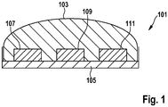
- Fig. 1 shows a sensor device 101.
- the sensor device 101 comprises a sensor capsule 103 and a holder 105 for fastening the sensor capsule 103 to a traffic infrastructure.
- the sensor capsule 103 is detachably fastened in the holder 105. This means that the sensor capsule 103 and the holder 105 are two separate components.
- the senor capsule 103 and the holder 105 form a common component, that is to say are formed integrally.
- a sensor 107 which is for example an environmental sensor, is arranged in the sensor capsule 103.
- sensor 107 is a parking sensor for detecting an occupied state of a parking position.
- An acceleration sensor 109 is also arranged within the sensor capsule 103.
- the acceleration sensor 109 it is possible to To measure or detect acceleration of the sensor capsule 103. For example, such acceleration can occur when the sensor capsule 103 is removed from its holder 105. Such an acceleration can occur, for example, when an external force acts on the sensor capsule 103. For example, such an acceleration can occur when the sensor capsule 103 is struck.
- a processor 111 is also arranged within the sensor capsule 103.
- the processor 111 is designed to detect an impermissible force action on the sensor capsule 103 based on the sensor data of the acceleration sensor 109.
- the processor 111 is designed to analyze or evaluate the acceleration data from the acceleration sensor 109, which correspond to a measured acceleration, in order to detect the impermissible force acting on the sensor capsule 103.
- an acceleration threshold value is provided, below which a measured acceleration is still classified as a permissible acceleration. This means that the force that led to this acceleration is still classified as a permissible force.
- Above the acceleration threshold it is provided that the measured acceleration is classified as an impermissible acceleration. Accordingly, the force that led to this acceleration is an impermissible force. In this case, an inadmissible force was exerted on the sensor capsule 103.
- the processor 111 is then designed to evaluate the sensor data of the respective sensors to determine whether an inadmissible force has acted on the sensor capsule 103 or has occurred. This is done in particular by comparing the sensor data with a threshold value, that is to say, for example, with a movement threshold value, position change threshold value, rotation rate threshold value, magnetic field threshold value.
- the processor 111 is in particular designed to detect an actual state of the sensor capsule 103 based on the sensor data of the respective sensors, for example an actual position or an actual position. The processor 111 can then accordingly determine a deviation from this actual state from the target state and classify the determined deviation as permissible or impermissible.
- additional sensors are provided in addition to or instead of the sensor 107.
- other environmental sensors are provided.
- a gas sensor is provided.
- a occupied state of a parking position can be detected by means of the sensor device 101.
- a traffic flow and / or a traffic density can be measured by means of the sensor device 101.
- a gas concentration in the surroundings of the sensor device 101 can be detected or measured by means of the sensor device 101.
- At least one of the following elements is additionally arranged within the sensor capsule 103: electrical energy store, microcontroller, data store, communication interface.
- the invention thus particularly and inter alia includes the idea of, for example, detecting an undesired external influence on the sensor device.
- An undesired external influence of this type that is to say generally the impermissible force, can be reported to an operator of the sensor device, for example. This is particularly the case in that a message informing about the impermissible force action is transmitted by means of a communication interface in the event of a detected impermissible force action.
- one or more of the sensors which are arranged within the sensor capsule are deactivated when the external influence and / or theft, that is to say generally an impermissible force effect, are detected. This especially before a Transmission of a message, in particular before a transmission of the message to a system center and / or to an operator, or only after a transmission of the message.
- the idea according to the invention thus includes, in particular, inserting an additional sensor element into a sensor capsule.
- this sensor is intended to detect improper movement and a change in position of the sensor capsule.
- This additional sensor element is therefore in particular a sensor, for example a motion sensor, an acceleration sensor, a position sensor, rotation rate sensor or magnetic sensor.
- several additional sensor elements are provided.
- the additional sensor element thus includes in particular sensors for position detection and / or movement detection, in particular an acceleration sensor and / or a rotation rate sensor and / or a magnetic sensor.
- a positional deviation of the sensor capsule from an original installation position corresponds, for example, to improper removal
- an external shock corresponds to, for example, vandalism
- motion detection corresponds to, for example, an improper removal
- this detected positional deviation or external shock or movement detection is transmitted by means of a communication interface.
- a communication interface For example, to an operator of the sensor device. This means that via an existing radio connectivity provided by the sensor capsule (here communication interface) it is communicated to the operator that a positional deviation or an external shock or a movement detection has taken place.
- further data such as position data and / or a time stamp, which are recorded by the sensors of the sensor capsule or are stored therein, are transmitted or sent out via the communication interface as required.
- an external monitoring device for monitoring the sensor device is activated in response to receipt of this data and / or the message.
- the external monitoring device comprises one or more environment sensors.
- These environment sensors can be, for example, one of the environment sensors mentioned above.
- an automated service technician call is provided, for example, in response to receipt of the message and / or the data.
- a correct position (target position) of the sensor capsule (generally a correct state, that is to say a target state) is taught in when the sensor capsule is installed for the first time together with a configuration of the further operating parameters.
- a one-piece sensor device denotes a sensor device in which the sensor capsule and the holder are formed as a common component.
- the concept according to the invention can therefore be used in particular for parking sensors for parking space management.
- it can inventive concept for sensors for measuring and / or monitoring a traffic flow and / or a traffic density can be applied.
- the concept according to the invention can be used for sensors for monitoring container occupancy and / or monitoring in a container warehouse.
- the concept according to the invention can be used for environmental sensors inside and / or outside of buildings.
- An environmental sensor is, for example, a gas sensor.
Landscapes
- General Physics & Mathematics (AREA)
- Physics & Mathematics (AREA)
- Engineering & Computer Science (AREA)
- Civil Engineering (AREA)
- Structural Engineering (AREA)
- Architecture (AREA)
- General Engineering & Computer Science (AREA)
- Arrangements For Transmission Of Measured Signals (AREA)
- Burglar Alarm Systems (AREA)
- Emergency Alarm Devices (AREA)
- Alarm Systems (AREA)
- Traffic Control Systems (AREA)
- Testing Or Calibration Of Command Recording Devices (AREA)
Claims (11)
- Dispositif de détection (101), comprenant :- une capsule de détection (103),- à l'intérieur de laquelle sont disposés un ou plusieurs capteurs (107, 109),- un support (105) permettant la fixation de la capsule de détection (103) sur une infrastructure routière, dans lequel- un processeur (111), conçu pour détecter, à partir des données de détection de l'un ou de plusieurs desdits un ou plusieurs capteurs (107, 109), l'application illicite d'une force à la capsule de détection (103), est disposé dans la capsule de détection (103),- comprenant en outre une interface de communication qui est conçue, lorsque l'application illicite d'une force est détectée, pour transmettre un message informant sur l'application illicite d'une force et des données de détection dudit un ou desdits multiples capteurs (107, 109),- dans lequel l'interface de communication et/ou le processeur (111) sont conçus pour doter le message à transmettre et/ou les données de détection à transmettre d'un marqueur temporel en cas d'application illicite d'une force.
- Dispositif de détection (101) selon la revendication 1, dans lequel ledit un ou lesdits multiples capteurs (107, 109) comprennent un capteur de position destiné à détecter une position de la capsule de détection (103), de manière à ce que les données de détection transmises au moyen de l'interface de communication comprennent des données de position correspondant à la position détectée.
- Dispositif de détection (101) selon l'une des revendications 1 à 2, dans lequel le message comprend une instruction d'activation pour un dispositif de surveillance destiné à surveiller le dispositif de détection (201), de manière à ce que le dispositif de surveillance puisse être activé en réponse à l'instruction d'activation afin de surveiller le dispositif de détection (201).
- Dispositif de détection (101) selon l'une des revendications précédentes, dans lequel le processeur (111) est conçu pour détecter, à partir des données de détection, un écart d'un état réel de la capsule de détection (103) par rapport à un état de consigne de la capsule de détection (103), dans lequel le processeur (111) est conçu pour détecter l'application illicite d'une force sur la capsule de détection (103) à partir de la détection de l'écart.
- Dispositif de détection (101) selon la revendication 4, dans lequel le processeur (111) est conçu pour définir à partir des données de détection un état réel actuel de la capsule de détection (103) en tant qu'état de consigne.
- Dispositif de détection (101) selon l'une des revendications précédentes, dans lequel le processeur (111) est conçu pour désactiver un ou plusieurs desdits un ou plusieurs capteurs (107, 109) lors de l'application illicite d'une force sur la capsule de détection (103).
- Dispositif de détection (101) selon l'une des revendications précédentes, dans lequel la capsule de détection (103) est fixée de manière amovible dans le support (105).
- Dispositif de détection (101) selon l'une des revendications 1 à 6, dans lequel la capsule de détection (103) et le support (105) sont formés d'un seul tenant.
- Dispositif de détection (101) selon l'une des revendications précédentes, dans lequel le support (105) est fixé à une infrastructure routière.
- Dispositif de détection (101) selon l'une des revendications précédentes, dans lequel le ou les capteurs (107, 109) comprennent un ou plusieurs des capteurs suivants : un capteur d'environnement (107), un capteur de stationnement pour détecter un état d'occupation d'un emplacement de stationnement, un capteur de trafic pour surveiller un flux de trafic et/ou pour mesurer une densité de trafic et/ou un capteur de stationnement pour surveiller une occupation de conteneurs et/ou un capteur d'environnement, en particulier un capteur de gaz.
- Dispositif de détection (101) selon l'une des revendications précédentes, dans lequel le ou les capteurs (107, 109) à partir desquels le processeur (111) peut détecter l'application illicite d'une force sur la capsule de détection (103) comprennent un ou plusieurs des capteurs suivants : capteur de mouvement, capteur d'accélération (109), capteur de position, capteur de vitesse de rotation et capteur magnétique.
Applications Claiming Priority (2)
| Application Number | Priority Date | Filing Date | Title |
|---|---|---|---|
| DE102015202781.3A DE102015202781A1 (de) | 2015-02-17 | 2015-02-17 | Sensorvorrichtung |
| PCT/EP2016/051628 WO2016131618A1 (fr) | 2015-02-17 | 2016-01-27 | Dispositif de détection |
Publications (2)
| Publication Number | Publication Date |
|---|---|
| EP3259560A1 EP3259560A1 (fr) | 2017-12-27 |
| EP3259560B1 true EP3259560B1 (fr) | 2020-06-17 |
Family
ID=55236365
Family Applications (1)
| Application Number | Title | Priority Date | Filing Date |
|---|---|---|---|
| EP16701646.8A Not-in-force EP3259560B1 (fr) | 2015-02-17 | 2016-01-27 | Dispositif de détection |
Country Status (6)
| Country | Link |
|---|---|
| US (1) | US10502595B2 (fr) |
| EP (1) | EP3259560B1 (fr) |
| JP (1) | JP2018511114A (fr) |
| CN (1) | CN107250734A (fr) |
| DE (1) | DE102015202781A1 (fr) |
| WO (1) | WO2016131618A1 (fr) |
Families Citing this family (2)
| Publication number | Priority date | Publication date | Assignee | Title |
|---|---|---|---|---|
| JP6801157B2 (ja) * | 2017-03-13 | 2020-12-16 | オムロン株式会社 | 環境センサ |
| JP7406627B2 (ja) | 2019-09-27 | 2023-12-27 | コルシュ アーゲー | プレスパンチに取り付けられた測定装置によって錠剤プレス機を好ましくは継続的な動作中に監視する装置及び方法 |
Citations (3)
| Publication number | Priority date | Publication date | Assignee | Title |
|---|---|---|---|---|
| EP0259523A1 (fr) * | 1986-09-11 | 1988-03-16 | Philips S.p.A. | Dispositif de pesage dynamique statistique de véhicules et/ou de comptage des essieux de camions ou de fardiers |
| EP1227452A1 (fr) * | 2001-01-19 | 2002-07-31 | Siemens Building Technologies AG | Système de sécurité et avertisseur de danger pour surveiller des paramètres de risque |
| US20120007749A1 (en) * | 2010-07-07 | 2012-01-12 | Stallion Systems, Inc. | System for Identifying Vehicles in a Parking Facility |
Family Cites Families (28)
| Publication number | Priority date | Publication date | Assignee | Title |
|---|---|---|---|---|
| US3911390A (en) * | 1973-11-07 | 1975-10-07 | Richard H Myers | Traffic sensor strip |
| FR2532601A1 (fr) | 1982-09-03 | 1984-03-09 | Martin Jacques | Appareil pour detecter la presence et surveiller un vehicule gare |
| FR2662006A1 (fr) * | 1990-05-11 | 1991-11-15 | Thermocoax Cie | Dispositif de detection de donnees relatives au passage de vehicules sur une chaussee. |
| US5239148A (en) * | 1991-05-15 | 1993-08-24 | Progressive Engineering Technologies Corp. | Lane discriminating traffic counting device |
| US5710558A (en) * | 1996-01-16 | 1998-01-20 | Gibson; Guy P. | Traffic sensor for roadway placement |
| GB9602116D0 (en) | 1996-02-02 | 1996-04-03 | Graham Alan R | Burglar detector |
| CN2517631Y (zh) | 2001-07-23 | 2002-10-23 | 刘晖 | 基于位移信息的汽车防盗探测器 |
| EP1774489A1 (fr) | 2004-07-08 | 2007-04-18 | Iem Sa | Borne de detection et methode pour surveiller une place de stationnement a l'aide d'une telle borne |
| US8800390B2 (en) * | 2006-02-07 | 2014-08-12 | Michelin Recherche Et Technique S.A. | Contact detector with piezoelectric sensor |
| CN201438327U (zh) * | 2009-04-04 | 2010-04-14 | 广州中沙桥汽车用品有限公司 | 防盗报警装置 |
| WO2011011405A2 (fr) | 2009-07-20 | 2011-01-27 | University Of Memphis Research Foundation | Systèmes et procédés de détection de vols |
| FR2955453B1 (fr) * | 2010-01-21 | 2013-01-11 | Eco Compteur | Boitier electronique destine a etre fixe sous un couvercle d'un regard |
| CN101857008B (zh) | 2010-04-29 | 2011-09-28 | 路军 | 一种车用主动式智能安全监控仪器 |
| WO2011153114A2 (fr) * | 2010-05-31 | 2011-12-08 | Central Signal, Llc | Détection de trains |
| CN201725438U (zh) | 2010-06-12 | 2011-01-26 | 东莞市帕马智能停车服务有限公司 | 一种车位监测无线传感器 |
| JP5536554B2 (ja) | 2010-06-16 | 2014-07-02 | 矢崎エナジーシステム株式会社 | 携帯型coガス検出装置及びガス発生監視装置並びにこれらを備えるガス発生監視システム |
| CN201740537U (zh) | 2010-07-19 | 2011-02-09 | 凯迈(洛阳)测控有限公司 | 一种路面状况传感器及其封装组件外形与外壳 |
| CN202008744U (zh) | 2010-12-24 | 2011-10-12 | 无锡物联网产业研究院 | 车辆探测器及车辆探测系统 |
| US20130271292A1 (en) * | 2011-10-09 | 2013-10-17 | James Andrew McDermott | Driver Alert and Monitoring System |
| CH706539A1 (de) * | 2012-05-16 | 2013-11-29 | Kistler Holding Ag | Sensormodul eines WIM-Systems und Messverfahren. |
| EP2720068A1 (fr) * | 2012-10-09 | 2014-04-16 | Sercel | Dispositif de couplage pour capteurs sismiques |
| KR101428358B1 (ko) | 2013-01-08 | 2014-08-07 | 엘지이노텍 주식회사 | 센서모듈 |
| JP6077909B2 (ja) | 2013-03-29 | 2017-02-08 | 綜合警備保障株式会社 | 侵入検知システム及び侵入検知方法 |
| JP6237982B2 (ja) | 2013-04-23 | 2017-11-29 | セイコーエプソン株式会社 | 物理量センサー、電子機器及び移動体 |
| CN203479827U (zh) | 2013-10-16 | 2014-03-12 | 盛发电力科技(厦门)有限公司 | 用于变压器防盗的数字式位移传感器 |
| FR3022674B1 (fr) * | 2014-06-18 | 2019-12-13 | Iem Sarl | Borne de detection comprenant un transducteur piezoelectrique fixe a une membrane liee a une structure de butee |
| DE102015202780A1 (de) * | 2015-02-17 | 2016-08-18 | Robert Bosch Gmbh | Sensorvorrichtung |
| US10909389B2 (en) * | 2016-09-20 | 2021-02-02 | Apple Inc. | Traffic direction gesture recognition |
-
2015
- 2015-02-17 DE DE102015202781.3A patent/DE102015202781A1/de not_active Withdrawn
-
2016
- 2016-01-27 JP JP2017543788A patent/JP2018511114A/ja active Pending
- 2016-01-27 EP EP16701646.8A patent/EP3259560B1/fr not_active Not-in-force
- 2016-01-27 CN CN201680010707.8A patent/CN107250734A/zh active Pending
- 2016-01-27 US US15/544,217 patent/US10502595B2/en not_active Expired - Fee Related
- 2016-01-27 WO PCT/EP2016/051628 patent/WO2016131618A1/fr not_active Ceased
Patent Citations (3)
| Publication number | Priority date | Publication date | Assignee | Title |
|---|---|---|---|---|
| EP0259523A1 (fr) * | 1986-09-11 | 1988-03-16 | Philips S.p.A. | Dispositif de pesage dynamique statistique de véhicules et/ou de comptage des essieux de camions ou de fardiers |
| EP1227452A1 (fr) * | 2001-01-19 | 2002-07-31 | Siemens Building Technologies AG | Système de sécurité et avertisseur de danger pour surveiller des paramètres de risque |
| US20120007749A1 (en) * | 2010-07-07 | 2012-01-12 | Stallion Systems, Inc. | System for Identifying Vehicles in a Parking Facility |
Also Published As
| Publication number | Publication date |
|---|---|
| CN107250734A (zh) | 2017-10-13 |
| WO2016131618A1 (fr) | 2016-08-25 |
| EP3259560A1 (fr) | 2017-12-27 |
| US10502595B2 (en) | 2019-12-10 |
| JP2018511114A (ja) | 2018-04-19 |
| US20180313674A1 (en) | 2018-11-01 |
| DE102015202781A1 (de) | 2016-08-18 |
Similar Documents
| Publication | Publication Date | Title |
|---|---|---|
| EP3259561B1 (fr) | Dsipositif de détection | |
| DE102016219455B4 (de) | Verfahren und aktive Infrastruktur zur Überprüfung einer Umfelderfassung eines Kraftfahrzeugs | |
| EP3052359B1 (fr) | Procédé et dispositif pour surveiller le fonctionnement d'un système d'aide à la conduite | |
| DE102014226020A1 (de) | Verfahren und Vorrichtung zur Kalibrierung mindestens einer mobilen Sensoreinrichtung | |
| DE102013212351A1 (de) | System zum Erfassen von Komponenten eines Fahrzeugs | |
| EP3259560B1 (fr) | Dispositif de détection | |
| DE202010006963U1 (de) | Mobiles Datengerät und System zum Lesen von Daten von einem Datenträger | |
| EP4327172B1 (fr) | Procédé de commande automatique d'un véhicule | |
| DE102011008654A1 (de) | Beschlagsintegrierte Überwachungseinrichtung | |
| DE102012212808A1 (de) | Verfahren und Vorrichtung zur Stillstandsüberwachung bei Schienenfahrzeugen | |
| EP4086400B1 (fr) | Système d'inspection de canal et/ou de maintenance | |
| DE202009013742U1 (de) | Fahrzeugerkennungsvorrichtung | |
| DE102014207810A1 (de) | Verfahren und Vorrichtung zum Betreiben eines Kraftfahrzeugs | |
| DE102005010671A1 (de) | Vorrichtung zur Überwachung der Funktion eines Anzeigeelements | |
| DE102013212344A1 (de) | Verfahren und Vorrichtung zum Aktualisieren der Software eines Kfz-Steuergeräts | |
| DE102017213692A1 (de) | Verfahren, Vorrichtung, mobiles Anwendergerät, Computerprogramm zum maschinellen Lernen für ein Sensorsystem eines Fahrzeugs | |
| EP3659032B1 (fr) | Procédé de fonctionnement d'un appareil de commande et dispositif doté de l'appareil de commande correspondant | |
| EP3980223A1 (fr) | Procédé et système permettant d'assurer automatiquement le fonctionnement d'un système de robot commandé au moyen d'un dispositif d'actionnement mobile | |
| EP1895329A2 (fr) | Dispositif destiné à la saisie d'objets dans une zone de surveillance | |
| EP3376485B1 (fr) | Unité d'émission de signal à canal de retour intégré | |
| DE102019206802B4 (de) | Messgerät für die Automatisierungstechnik mit optischer Datenübertragung | |
| EP2178060A2 (fr) | Poteau de signalisation | |
| EP4226351A1 (fr) | Centrale d'alarme incendie | |
| DE102024208668B3 (de) | Verfahren und Vorrichtung zum Bestimmen einer Degradierung von Umfelderfassungssystemen von Fahrzeugen einer Fahrzeugflotte | |
| DE102010030667A1 (de) | Vorrichtung zur Überwachung einer Position und/oder einer Bewegung wenigstens eines Objekts im Bezug auf einen vorgegebenen Bereich, insbesondere Gefahrenbereich, einer Anlage sowie Anlage mit einer Mehrzahl an Vorrichtungen |
Legal Events
| Date | Code | Title | Description |
|---|---|---|---|
| STAA | Information on the status of an ep patent application or granted ep patent |
Free format text: STATUS: THE INTERNATIONAL PUBLICATION HAS BEEN MADE |
|
| PUAI | Public reference made under article 153(3) epc to a published international application that has entered the european phase |
Free format text: ORIGINAL CODE: 0009012 |
|
| STAA | Information on the status of an ep patent application or granted ep patent |
Free format text: STATUS: REQUEST FOR EXAMINATION WAS MADE |
|
| 17P | Request for examination filed |
Effective date: 20170918 |
|
| AK | Designated contracting states |
Kind code of ref document: A1 Designated state(s): AL AT BE BG CH CY CZ DE DK EE ES FI FR GB GR HR HU IE IS IT LI LT LU LV MC MK MT NL NO PL PT RO RS SE SI SK SM TR |
|
| AX | Request for extension of the european patent |
Extension state: BA ME |
|
| DAV | Request for validation of the european patent (deleted) | ||
| DAX | Request for extension of the european patent (deleted) | ||
| STAA | Information on the status of an ep patent application or granted ep patent |
Free format text: STATUS: EXAMINATION IS IN PROGRESS |
|
| 17Q | First examination report despatched |
Effective date: 20180621 |
|
| GRAP | Despatch of communication of intention to grant a patent |
Free format text: ORIGINAL CODE: EPIDOSNIGR1 |
|
| STAA | Information on the status of an ep patent application or granted ep patent |
Free format text: STATUS: GRANT OF PATENT IS INTENDED |
|
| INTG | Intention to grant announced |
Effective date: 20200117 |
|
| RAP1 | Party data changed (applicant data changed or rights of an application transferred) |
Owner name: ROBERT BOSCH GMBH |
|
| GRAS | Grant fee paid |
Free format text: ORIGINAL CODE: EPIDOSNIGR3 |
|
| GRAA | (expected) grant |
Free format text: ORIGINAL CODE: 0009210 |
|
| STAA | Information on the status of an ep patent application or granted ep patent |
Free format text: STATUS: THE PATENT HAS BEEN GRANTED |
|
| AK | Designated contracting states |
Kind code of ref document: B1 Designated state(s): AL AT BE BG CH CY CZ DE DK EE ES FI FR GB GR HR HU IE IS IT LI LT LU LV MC MK MT NL NO PL PT RO RS SE SI SK SM TR |
|
| REG | Reference to a national code |
Ref country code: GB Ref legal event code: FG4D Free format text: NOT ENGLISH |
|
| REG | Reference to a national code |
Ref country code: CH Ref legal event code: EP |
|
| REG | Reference to a national code |
Ref country code: IE Ref legal event code: FG4D Free format text: LANGUAGE OF EP DOCUMENT: GERMAN |
|
| REG | Reference to a national code |
Ref country code: DE Ref legal event code: R096 Ref document number: 502016010239 Country of ref document: DE |
|
| REG | Reference to a national code |
Ref country code: AT Ref legal event code: REF Ref document number: 1281856 Country of ref document: AT Kind code of ref document: T Effective date: 20200715 |
|
| PG25 | Lapsed in a contracting state [announced via postgrant information from national office to epo] |
Ref country code: LT Free format text: LAPSE BECAUSE OF FAILURE TO SUBMIT A TRANSLATION OF THE DESCRIPTION OR TO PAY THE FEE WITHIN THE PRESCRIBED TIME-LIMIT Effective date: 20200617 Ref country code: FI Free format text: LAPSE BECAUSE OF FAILURE TO SUBMIT A TRANSLATION OF THE DESCRIPTION OR TO PAY THE FEE WITHIN THE PRESCRIBED TIME-LIMIT Effective date: 20200617 Ref country code: NO Free format text: LAPSE BECAUSE OF FAILURE TO SUBMIT A TRANSLATION OF THE DESCRIPTION OR TO PAY THE FEE WITHIN THE PRESCRIBED TIME-LIMIT Effective date: 20200917 Ref country code: GR Free format text: LAPSE BECAUSE OF FAILURE TO SUBMIT A TRANSLATION OF THE DESCRIPTION OR TO PAY THE FEE WITHIN THE PRESCRIBED TIME-LIMIT Effective date: 20200918 Ref country code: SE Free format text: LAPSE BECAUSE OF FAILURE TO SUBMIT A TRANSLATION OF THE DESCRIPTION OR TO PAY THE FEE WITHIN THE PRESCRIBED TIME-LIMIT Effective date: 20200617 |
|
| REG | Reference to a national code |
Ref country code: LT Ref legal event code: MG4D |
|
| REG | Reference to a national code |
Ref country code: NL Ref legal event code: MP Effective date: 20200617 |
|
| PG25 | Lapsed in a contracting state [announced via postgrant information from national office to epo] |
Ref country code: BG Free format text: LAPSE BECAUSE OF FAILURE TO SUBMIT A TRANSLATION OF THE DESCRIPTION OR TO PAY THE FEE WITHIN THE PRESCRIBED TIME-LIMIT Effective date: 20200917 Ref country code: RS Free format text: LAPSE BECAUSE OF FAILURE TO SUBMIT A TRANSLATION OF THE DESCRIPTION OR TO PAY THE FEE WITHIN THE PRESCRIBED TIME-LIMIT Effective date: 20200617 Ref country code: HR Free format text: LAPSE BECAUSE OF FAILURE TO SUBMIT A TRANSLATION OF THE DESCRIPTION OR TO PAY THE FEE WITHIN THE PRESCRIBED TIME-LIMIT Effective date: 20200617 Ref country code: LV Free format text: LAPSE BECAUSE OF FAILURE TO SUBMIT A TRANSLATION OF THE DESCRIPTION OR TO PAY THE FEE WITHIN THE PRESCRIBED TIME-LIMIT Effective date: 20200617 |
|
| PG25 | Lapsed in a contracting state [announced via postgrant information from national office to epo] |
Ref country code: AL Free format text: LAPSE BECAUSE OF FAILURE TO SUBMIT A TRANSLATION OF THE DESCRIPTION OR TO PAY THE FEE WITHIN THE PRESCRIBED TIME-LIMIT Effective date: 20200617 Ref country code: NL Free format text: LAPSE BECAUSE OF FAILURE TO SUBMIT A TRANSLATION OF THE DESCRIPTION OR TO PAY THE FEE WITHIN THE PRESCRIBED TIME-LIMIT Effective date: 20200617 |
|
| PG25 | Lapsed in a contracting state [announced via postgrant information from national office to epo] |
Ref country code: EE Free format text: LAPSE BECAUSE OF FAILURE TO SUBMIT A TRANSLATION OF THE DESCRIPTION OR TO PAY THE FEE WITHIN THE PRESCRIBED TIME-LIMIT Effective date: 20200617 Ref country code: SM Free format text: LAPSE BECAUSE OF FAILURE TO SUBMIT A TRANSLATION OF THE DESCRIPTION OR TO PAY THE FEE WITHIN THE PRESCRIBED TIME-LIMIT Effective date: 20200617 Ref country code: RO Free format text: LAPSE BECAUSE OF FAILURE TO SUBMIT A TRANSLATION OF THE DESCRIPTION OR TO PAY THE FEE WITHIN THE PRESCRIBED TIME-LIMIT Effective date: 20200617 Ref country code: IT Free format text: LAPSE BECAUSE OF FAILURE TO SUBMIT A TRANSLATION OF THE DESCRIPTION OR TO PAY THE FEE WITHIN THE PRESCRIBED TIME-LIMIT Effective date: 20200617 Ref country code: CZ Free format text: LAPSE BECAUSE OF FAILURE TO SUBMIT A TRANSLATION OF THE DESCRIPTION OR TO PAY THE FEE WITHIN THE PRESCRIBED TIME-LIMIT Effective date: 20200617 Ref country code: ES Free format text: LAPSE BECAUSE OF FAILURE TO SUBMIT A TRANSLATION OF THE DESCRIPTION OR TO PAY THE FEE WITHIN THE PRESCRIBED TIME-LIMIT Effective date: 20200617 Ref country code: PT Free format text: LAPSE BECAUSE OF FAILURE TO SUBMIT A TRANSLATION OF THE DESCRIPTION OR TO PAY THE FEE WITHIN THE PRESCRIBED TIME-LIMIT Effective date: 20201019 |
|
| PG25 | Lapsed in a contracting state [announced via postgrant information from national office to epo] |
Ref country code: IS Free format text: LAPSE BECAUSE OF FAILURE TO SUBMIT A TRANSLATION OF THE DESCRIPTION OR TO PAY THE FEE WITHIN THE PRESCRIBED TIME-LIMIT Effective date: 20201017 Ref country code: SK Free format text: LAPSE BECAUSE OF FAILURE TO SUBMIT A TRANSLATION OF THE DESCRIPTION OR TO PAY THE FEE WITHIN THE PRESCRIBED TIME-LIMIT Effective date: 20200617 Ref country code: PL Free format text: LAPSE BECAUSE OF FAILURE TO SUBMIT A TRANSLATION OF THE DESCRIPTION OR TO PAY THE FEE WITHIN THE PRESCRIBED TIME-LIMIT Effective date: 20200617 |
|
| REG | Reference to a national code |
Ref country code: DE Ref legal event code: R097 Ref document number: 502016010239 Country of ref document: DE |
|
| PLBE | No opposition filed within time limit |
Free format text: ORIGINAL CODE: 0009261 |
|
| STAA | Information on the status of an ep patent application or granted ep patent |
Free format text: STATUS: NO OPPOSITION FILED WITHIN TIME LIMIT |
|
| PG25 | Lapsed in a contracting state [announced via postgrant information from national office to epo] |
Ref country code: DK Free format text: LAPSE BECAUSE OF FAILURE TO SUBMIT A TRANSLATION OF THE DESCRIPTION OR TO PAY THE FEE WITHIN THE PRESCRIBED TIME-LIMIT Effective date: 20200617 |
|
| 26N | No opposition filed |
Effective date: 20210318 |
|
| PG25 | Lapsed in a contracting state [announced via postgrant information from national office to epo] |
Ref country code: SI Free format text: LAPSE BECAUSE OF FAILURE TO SUBMIT A TRANSLATION OF THE DESCRIPTION OR TO PAY THE FEE WITHIN THE PRESCRIBED TIME-LIMIT Effective date: 20200617 |
|
| PG25 | Lapsed in a contracting state [announced via postgrant information from national office to epo] |
Ref country code: MC Free format text: LAPSE BECAUSE OF FAILURE TO SUBMIT A TRANSLATION OF THE DESCRIPTION OR TO PAY THE FEE WITHIN THE PRESCRIBED TIME-LIMIT Effective date: 20200617 |
|
| REG | Reference to a national code |
Ref country code: CH Ref legal event code: PL |
|
| GBPC | Gb: european patent ceased through non-payment of renewal fee |
Effective date: 20210127 |
|
| PG25 | Lapsed in a contracting state [announced via postgrant information from national office to epo] |
Ref country code: LU Free format text: LAPSE BECAUSE OF NON-PAYMENT OF DUE FEES Effective date: 20210127 |
|
| REG | Reference to a national code |
Ref country code: BE Ref legal event code: MM Effective date: 20210131 |
|
| PG25 | Lapsed in a contracting state [announced via postgrant information from national office to epo] |
Ref country code: LI Free format text: LAPSE BECAUSE OF NON-PAYMENT OF DUE FEES Effective date: 20210131 Ref country code: GB Free format text: LAPSE BECAUSE OF NON-PAYMENT OF DUE FEES Effective date: 20210127 Ref country code: CH Free format text: LAPSE BECAUSE OF NON-PAYMENT OF DUE FEES Effective date: 20210131 |
|
| PG25 | Lapsed in a contracting state [announced via postgrant information from national office to epo] |
Ref country code: IE Free format text: LAPSE BECAUSE OF NON-PAYMENT OF DUE FEES Effective date: 20210127 |
|
| REG | Reference to a national code |
Ref country code: AT Ref legal event code: MM01 Ref document number: 1281856 Country of ref document: AT Kind code of ref document: T Effective date: 20210127 |
|
| PG25 | Lapsed in a contracting state [announced via postgrant information from national office to epo] |
Ref country code: AT Free format text: LAPSE BECAUSE OF NON-PAYMENT OF DUE FEES Effective date: 20210127 |
|
| PGFP | Annual fee paid to national office [announced via postgrant information from national office to epo] |
Ref country code: DE Payment date: 20220324 Year of fee payment: 7 |
|
| PG25 | Lapsed in a contracting state [announced via postgrant information from national office to epo] |
Ref country code: IS Free format text: LAPSE BECAUSE OF FAILURE TO SUBMIT A TRANSLATION OF THE DESCRIPTION OR TO PAY THE FEE WITHIN THE PRESCRIBED TIME-LIMIT Effective date: 20201017 |
|
| PGFP | Annual fee paid to national office [announced via postgrant information from national office to epo] |
Ref country code: FR Payment date: 20220120 Year of fee payment: 7 |
|
| PG25 | Lapsed in a contracting state [announced via postgrant information from national office to epo] |
Ref country code: BE Free format text: LAPSE BECAUSE OF NON-PAYMENT OF DUE FEES Effective date: 20210131 |
|
| PG25 | Lapsed in a contracting state [announced via postgrant information from national office to epo] |
Ref country code: CY Free format text: LAPSE BECAUSE OF FAILURE TO SUBMIT A TRANSLATION OF THE DESCRIPTION OR TO PAY THE FEE WITHIN THE PRESCRIBED TIME-LIMIT Effective date: 20200617 |
|
| PG25 | Lapsed in a contracting state [announced via postgrant information from national office to epo] |
Ref country code: HU Free format text: LAPSE BECAUSE OF FAILURE TO SUBMIT A TRANSLATION OF THE DESCRIPTION OR TO PAY THE FEE WITHIN THE PRESCRIBED TIME-LIMIT; INVALID AB INITIO Effective date: 20160127 |
|
| REG | Reference to a national code |
Ref country code: DE Ref legal event code: R119 Ref document number: 502016010239 Country of ref document: DE |
|
| PG25 | Lapsed in a contracting state [announced via postgrant information from national office to epo] |
Ref country code: DE Free format text: LAPSE BECAUSE OF NON-PAYMENT OF DUE FEES Effective date: 20230801 |
|
| PG25 | Lapsed in a contracting state [announced via postgrant information from national office to epo] |
Ref country code: FR Free format text: LAPSE BECAUSE OF NON-PAYMENT OF DUE FEES Effective date: 20230131 |
|
| PG25 | Lapsed in a contracting state [announced via postgrant information from national office to epo] |
Ref country code: MK Free format text: LAPSE BECAUSE OF FAILURE TO SUBMIT A TRANSLATION OF THE DESCRIPTION OR TO PAY THE FEE WITHIN THE PRESCRIBED TIME-LIMIT Effective date: 20200617 |
|
| PG25 | Lapsed in a contracting state [announced via postgrant information from national office to epo] |
Ref country code: MT Free format text: LAPSE BECAUSE OF FAILURE TO SUBMIT A TRANSLATION OF THE DESCRIPTION OR TO PAY THE FEE WITHIN THE PRESCRIBED TIME-LIMIT Effective date: 20200617 |
|
| PG25 | Lapsed in a contracting state [announced via postgrant information from national office to epo] |
Ref country code: TR Free format text: LAPSE BECAUSE OF FAILURE TO SUBMIT A TRANSLATION OF THE DESCRIPTION OR TO PAY THE FEE WITHIN THE PRESCRIBED TIME-LIMIT Effective date: 20200617 |