EP3260348B1 - Dispositif et procédé pour monter un équipement sous le plancher d'un véhicule ferroviaire - Google Patents
Dispositif et procédé pour monter un équipement sous le plancher d'un véhicule ferroviaire Download PDFInfo
- Publication number
- EP3260348B1 EP3260348B1 EP15882603.2A EP15882603A EP3260348B1 EP 3260348 B1 EP3260348 B1 EP 3260348B1 EP 15882603 A EP15882603 A EP 15882603A EP 3260348 B1 EP3260348 B1 EP 3260348B1
- Authority
- EP
- European Patent Office
- Prior art keywords
- truck
- equipment
- stage
- railway vehicle
- floor
- Prior art date
- Legal status (The legal status is an assumption and is not a legal conclusion. Google has not performed a legal analysis and makes no representation as to the accuracy of the status listed.)
- Active
Links
Images




Classifications
-
- B—PERFORMING OPERATIONS; TRANSPORTING
- B66—HOISTING; LIFTING; HAULING
- B66F—HOISTING, LIFTING, HAULING OR PUSHING, NOT OTHERWISE PROVIDED FOR, e.g. DEVICES WHICH APPLY A LIFTING OR PUSHING FORCE DIRECTLY TO THE SURFACE OF A LOAD
- B66F7/00—Lifting frames, e.g. for lifting vehicles; Platform lifts
- B66F7/06—Lifting frames, e.g. for lifting vehicles; Platform lifts with platforms supported by levers for vertical movement
- B66F7/065—Scissor linkages, i.e. X-configuration
-
- B—PERFORMING OPERATIONS; TRANSPORTING
- B61—RAILWAYS
- B61C—LOCOMOTIVES; MOTOR RAILCARS
- B61C17/00—Arrangement or disposition of parts; Details or accessories not otherwise provided for; Use of control gear and control systems
-
- B—PERFORMING OPERATIONS; TRANSPORTING
- B66—HOISTING; LIFTING; HAULING
- B66F—HOISTING, LIFTING, HAULING OR PUSHING, NOT OTHERWISE PROVIDED FOR, e.g. DEVICES WHICH APPLY A LIFTING OR PUSHING FORCE DIRECTLY TO THE SURFACE OF A LOAD
- B66F7/00—Lifting frames, e.g. for lifting vehicles; Platform lifts
- B66F7/06—Lifting frames, e.g. for lifting vehicles; Platform lifts with platforms supported by levers for vertical movement
- B66F7/0625—Lifting frames, e.g. for lifting vehicles; Platform lifts with platforms supported by levers for vertical movement with wheels for moving around the floor
-
- B—PERFORMING OPERATIONS; TRANSPORTING
- B62—LAND VEHICLES FOR TRAVELLING OTHERWISE THAN ON RAILS
- B62B—HAND-PROPELLED VEHICLES, e.g. HAND CARTS OR PERAMBULATORS; SLEDGES
- B62B2203/00—Grasping, holding, supporting the objects
- B62B2203/10—Grasping, holding, supporting the objects comprising lifting means
-
- B—PERFORMING OPERATIONS; TRANSPORTING
- B62—LAND VEHICLES FOR TRAVELLING OTHERWISE THAN ON RAILS
- B62B—HAND-PROPELLED VEHICLES, e.g. HAND CARTS OR PERAMBULATORS; SLEDGES
- B62B3/00—Hand carts having more than one axis carrying transport wheels; Steering devices therefor; Equipment therefor
- B62B3/04—Hand carts having more than one axis carrying transport wheels; Steering devices therefor; Equipment therefor involving means for grappling or securing in place objects to be carried; Loading or unloading equipment
- B62B3/06—Hand carts having more than one axis carrying transport wheels; Steering devices therefor; Equipment therefor involving means for grappling or securing in place objects to be carried; Loading or unloading equipment for simply clearing the load from the ground
- B62B3/0625—Hand carts having more than one axis carrying transport wheels; Steering devices therefor; Equipment therefor involving means for grappling or securing in place objects to be carried; Loading or unloading equipment for simply clearing the load from the ground using rigid mechanical lifting mechanisms, e.g. levers, cams or gears
-
- B—PERFORMING OPERATIONS; TRANSPORTING
- B62—LAND VEHICLES FOR TRAVELLING OTHERWISE THAN ON RAILS
- B62B—HAND-PROPELLED VEHICLES, e.g. HAND CARTS OR PERAMBULATORS; SLEDGES
- B62B3/00—Hand carts having more than one axis carrying transport wheels; Steering devices therefor; Equipment therefor
- B62B3/04—Hand carts having more than one axis carrying transport wheels; Steering devices therefor; Equipment therefor involving means for grappling or securing in place objects to be carried; Loading or unloading equipment
- B62B3/06—Hand carts having more than one axis carrying transport wheels; Steering devices therefor; Equipment therefor involving means for grappling or securing in place objects to be carried; Loading or unloading equipment for simply clearing the load from the ground
- B62B3/0643—Hand carts having more than one axis carrying transport wheels; Steering devices therefor; Equipment therefor involving means for grappling or securing in place objects to be carried; Loading or unloading equipment for simply clearing the load from the ground the wheels remaining stationary while the supporting surface is lifted
-
- B—PERFORMING OPERATIONS; TRANSPORTING
- B62—LAND VEHICLES FOR TRAVELLING OTHERWISE THAN ON RAILS
- B62B—HAND-PROPELLED VEHICLES, e.g. HAND CARTS OR PERAMBULATORS; SLEDGES
- B62B5/00—Accessories or details specially adapted for hand carts
- B62B5/0026—Propulsion aids
- B62B5/0063—Propulsion aids guiding, e.g. by a rail
Definitions
- the present invention relates to an apparatus for mounting equipment such as electric equipment, or an air brake apparatus under a floor of a railway vehicle, and a mounting method thereof.
- Equipment such as an auxiliary power supply, an emergency power supply (battery), a brake control device, an air tank is fixed under a floor of a railroad vehicle represented by a railway vehicle.
- each piece of equipment is individually mounted to a mounting position under the floor of the railroad vehicle. Therefore, when the positioning accuracy of the carrier truck and the lifting device is not achieved, it takes a lot of time to position each piece of the equipment at a corresponding position under the floor, causing a problem of poor workability.
- PTL 1 discloses an apparatus for improving efficiency of mounting work of underfloor equipment.
- a plurality of pieces of equipment are previously mounted on a common mounting frame, and the mounting frame is positioned and mounted under the floor (underframe) of the railroad vehicle to shorten an assembling time.
- JP57-037667-U proposes a device for mounting equipment under the floor of a rail vehicle.
- JP53-096552-U proposes a wheel-mounted frame which is moveable on rails.
- JP08-080848 A proposes a device for mounting equipment under the floor of a rail vehicle.
- an object of the present invention to provide an equipment mounting apparatus and an equipment mounting method that enable each piece of equipment to be easily positioned to the railroad vehicle without using an additional mounting member.
- a first aspect of the present invention provides an equipment mounting apparatus according to claim 1.
- a second aspect of the present invention provides a method for mounting equipment according to claim 6.
- the equipment mounting apparatus and the equipment mounting method that can easily position each piece of equipment to the railroad vehicle without using an additional mounting member.
- an equipment mounting apparatus and an equipment mounting method for mounting underfloor equipment such as an auxiliary power supply device and an air tank under a floor of the railway vehicle.
- railway vehicle is a generic term for vehicles that travel along a laid track, and includes, for example, a railroad vehicle, a street car, a new transport system vehicle, a monorail vehicle, or the like. Therefore, in the following description, a railroad vehicle will be exemplified as a representative railway vehicle, and an equipment mounting apparatus 1 and an equipment mounting method will be explained.
- a direction related to an operation of the equipment mounting apparatus 1 is defined.
- the width direction (railroad tie direction) of the railroad vehicle 5 is defined as X direction
- the longitudinal direction (rail direction) of the railroad vehicle 5 is defined as Y direction
- the height direction of the railroad vehicle 5 is defined as Z direction.
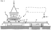
- FIG. 1 is a side view of the equipment mounting apparatus 1 according to the present invention
- FIG. 2 is a top view of the equipment mounting apparatus 1 according to the present invention.
- the equipment mounting apparatus 1 includes a first truck 20 that travels on a track 2 on which a temporary truck (not shown) that supports the railroad vehicle 5 rolls; a stage 10 that is disposed at a side position of the track 2 and capable of being coupled by the first truck 20; and a second truck 30 that travels on a guide traveling mechanism such as a guide rail that is laid on upper surfaces of the first truck 20 and the stage 10.
- a width dimension of the first truck 20 is set larger than a width dimension of a lower surface of the railroad vehicle 5 such that a moving area of the second truck that moves on the first truck can cover the entire lower surface of the railroad vehicle 5, and the guide traveling mechanism (e.g., a guide rail 22) is laid on the upper surface of the first truck 20 over the substantially entire width in X direction. Further, the first truck 20 has an axle 24 capable of moving in Y direction on the common track 2 and the temporary truck (not shown) that supports the railroad vehicle 5.
- axle 24 illustrated in FIG. 1 wheels that roll on the upper surface of the track 2 and these wheels connected by an axle shaft are illustrated, it is also possible, for example, to omit the axle shaft and use wheels that travel in a recess provided together with the track 2 (groove provided such that a flange of the wheel of the temporary truck that supports the railroad vehicle 5 can easily pass).
- the stage 10 is fixed on either one of roadbeds in X direction of the track 2 along the track 2, and a height of the upper surface of the stage 10 is substantially the same as a height of the upper surface of the first truck 20.
- the guide traveling mechanism e.g., a guide rail 12
- a gauge of the guide rail 12 is set to be same as the gauge of the guide rail 22 of the first truck described above, and the guide rail 12 and the guide rail 22 are disposed at the same position in Y direction, forming a common guide rail between the stage 10 and the first truck 20.
- the second truck 30 can move between the guide rail 22 of the first truck and the guide rail 12 of the stage 10.
- the second truck 30 can reciprocate between the guide rails 12 and 22 having the same gauge, a work of an operator can be made easier with a simple structure.
- a connecting device 40 is provided to restrain movement of the first truck 20 in Y direction.
- FIG. 3 is a top view of the connecting device of the equipment mounting apparatus 1 according to the present invention
- FIG. 4 is a cross sectional view (cross section B-B in FIG. 3 ) of the connecting device of the equipment mounting apparatus 1 according to the present invention.
- the connecting device 40 is configured by a hinge 46 fixed to the upper surface of the stage 10, and a locking part 44 fixed to the hinge 46.
- the locking part 44 can rotate around the hinge 46 as a fulcrum in a plane including X direction and Z direction (see FIG. 4 ).
- the tip part of the locking part 44 is inserted into a hole 42 provided on the upper surface of the first truck 20, restraining a relative movement in Y direction between the stage 10 and the first truck 20.
- the connecting device 40 When the stage 10 and the first truck 20 are connected by the connecting device 40, the guide rail 12 of the stage 10 and the guide rail 22 of the first truck 20 are connected. With a series of guide rails formed in this way, the second truck 30 can travel back and forth between the upper surfaces of the stage 10 and the first truck 20.
- FIG. 3 illustrates a case where the hinge 46 is provided on the stage 10, and the hole 42 to be inserted with the tip of the locking part 44 is provided to the first truck 20, the arrangement may be such that the hinge 46 is provided to the first truck 20, and the hole 42 is provided on the stage 10.
- an operator can simplify the work of coupling the stage 10 and the first truck 20.
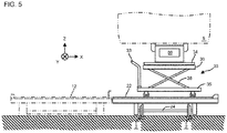
- FIG. 5 is a side view (cross section A-A in FIG. 2 ) illustrating a state in which equipment is being mounted under the floor of the vehicle by the equipment mounting apparatus 1 according to the present invention.
- the second truck 30 includes a pedestal 35 provided below with an axle that rolls on the guide rail 12 of the stage 10 and a guide rail 22 of the first truck 20; a lifting device 38 that is provided on the upper surface of the pedestal 35 and lifts stage 36 in Z direction; and a turntable 34 provided on the upper surface of a lifting table 36.
- a handrail 33 At an end portion of the pedestal 35 in X direction, there is provided a handrail 33 to be held by an operator in moving the second truck 30.
- the first truck 20 is moved to the side of the stage 10, and the stage 10 and the first truck 20 are connected by the connecting device 40. At this time, the railroad vehicle 5 is disposed above the first truck 20.
- equipment 80 to be mounted to the lower surface (under the floor) of the railroad vehicle 5, by a ceiling crane 95 (see FIG. 1 ) or a forklift (not shown).
- an axle 32 may be fixed with a stopper or the like to prevent the second truck 30 from rolling on the guide rail 22 of the first truck 20, as necessary.
- axle 32 that supports the second truck 30 to be capable of rolling may not necessarily have an axle shaft, and each wheel may be provided below the pedestal 35.
- the operator releases the connection between the stage 10 and the first truck 20 with the connecting device 40, and the first truck 20 mounted with the second truck 30 is moved along the track 2 to a downward position of the railroad vehicle 5 that is to be fixed with the underfloor equipment 80.
- the lifting device 38 is driven to raise the lifting table 36 and the turntable 34, and the mounting portion of the equipment 80 is abutted to the mounting portion under the floor of the railroad vehicle 5.
- the position can be adjusted by the turntable 34 provided to the second truck 30.
- the equipment 80 is fixed under the floor of the railroad vehicle 5 with a predetermined bolt or the like.
- the lifting device 38 is lowered and the first truck 20 is returned to a position where the first truck 20 can be connected to the stage 10, and then the first truck 20 is connected to the stage 10 by the connecting device 40. Thereafter, the second truck 30 is moved to the stage 10, and preparation for placing the next equipment on the second truck 30 is completed.
- FIGS. 6 and 7 an outline of a mounting apparatus in mounting an air tank under the floor of the railroad vehicle is shown.
- FIG. 6 is a side view illustrating a state in which the air tank is being mounted under the floor of the vehicle by the equipment mounting apparatus 1 according to the present invention
- FIG. 7 is a front view of the equipment mounting apparatus 1 (cross section C-C in FIG. 6 ) that mounts the air tank to the vehicle.
- a tank supporting device 90 is disposed on the upper surface of the turntable 34 of the second truck 30, and the air tank 82 is placed on the tank supporting device 90.
- the tank supporting device 90 is configured by a pedestal 91 and a tank supporting mechanism (equipment supporting mechanism) 92 that supports a body of the air tank 82.
- the tank supporting mechanism 92 is configured by two roller support parts 93 spaced apart by arranging the rotation axes of the rollers 94 on the same line, and a pair of the rotation axes of the respective rollers 94 are provided parallel to the pedestal 91.
- the air tank 82 is fixed to the upper surface of the pallet in a posture in which a mounting leg 84 faces downward, to be carried into the manufacturing site.
- the air tank 82 is lifted by the ceiling crane 95 in a posture in which the mounting leg 84 faces downward, and is placed on the tank supporting device 90.
- the air tank 82 placed on the tank supporting device 90 is rotated 180°over the rollers 94 around an axis of the air tank 82 to obtain a posture to be mounted under the floor of the railroad vehicle 5.
- the mounting apparatus includes a plurality of trucks corresponding to each of transporting directions. That is, the equipment 80 or the like is transported in X direction by the second truck 30, the equipment 80 or the like is transported in Y direction by the first truck 20, and the equipment 80 or the like is lifted in Z direction by the lifting device 38 of the second truck 30, and as necessary, the equipment 80 or the like is rotated on the horizontal plane by the turntable 34 of the second truck 30.
- the equipment 80 or the like is transported in X direction by the second truck 30
- the equipment 80 or the like is transported in Y direction by the first truck 20
- the equipment 80 or the like is lifted in Z direction by the lifting device 38 of the second truck 30, and as necessary, the equipment 80 or the like is rotated on the horizontal plane by the turntable 34 of the second truck 30.
- the mounting leg of the equipment 80 or the like is fixed to the lower surface of the railroad vehicle 5. Since the trucks each travel only along the respective guiding mechanisms, the trucks can move linearly toward the moving direction without consideration of unintended movement in the direction crossing the moving direction.
- the second truck 30 is supported on the axle 32, and the axle 32 rolls on the guide rail 12 and the guide rail 22. At this time, friction between the axle 32 and the guide rails 12 and 22 is small, so that a single operator can easily transport the equipment 80 or the like in X direction.
- the equipment 80 or the like is transported only in X direction, even if the center of gravity of the equipment 80 is high, it is only necessary to support an opposite side in the moving direction. Furthermore, since the friction is low, it is possible to safely and rapidly transport in X direction by a single operator with small man-hours, and also to improve the positioning accuracy.
- the first truck 20 is supported on the axle 24, and the axle 24 rolls on the track 2. Since the friction between the axle 24 and the track 2 is small, a single operator can easily and rapidly transport the equipment 80 or the like in Y direction.
- the equipment 80 or the like is transported only in Y direction, even if the center of gravity of the equipment 80 is high, it is only necessary to support an opposite side in the moving direction. Furthermore, since the friction is low, it is possible to safely and rapidly transport in Y direction by a single operator with small man-hours, and also to improve the positioning accuracy.
- a dimension of the first truck 20 in X direction is made larger than a dimension of the lower surface of the railroad vehicle 5 in X direction. Therefore, since the second truck 30 can be moved to a greater extent than the dimension of the lower surface of the railroad vehicle 5 in X direction, the equipment 80 or the like can also be rapidly and stably fixed on an end part in X direction of the lower surface of the railroad vehicle 5, by a single operator with small man-hours.
- the second truck 30 is installed with mounting the tank supporting device 90 that can be placed with the air tank 82 and can rotate the air tank 82 around the axis thereof to obtain an attachment posture, allowing a single operator to safely mount the equipment to the lower surface of the railroad vehicle 5, even if the posture of the equipment when being transported into the manufacturing site is different from the mounting posture to the lower surface of the railroad vehicle 5.
- a part of a configuration of an example may be replaced with a configuration of another example, and a configuration of an example may be added with a configuration of another example.
- the guide rail is provided on the stage and the first truck as the guide traveling mechanism
- a pair of grooves may be formed instead of the guide rail to guide traveling of the second truck.
Landscapes
- Engineering & Computer Science (AREA)
- Mechanical Engineering (AREA)
- Life Sciences & Earth Sciences (AREA)
- Geology (AREA)
- Structural Engineering (AREA)
- Automation & Control Theory (AREA)
- Transportation (AREA)
- Handcart (AREA)
- Machines For Laying And Maintaining Railways (AREA)
- Automatic Assembly (AREA)
Claims (7)
- Appareil de montage d'équipement (1) pour monter un équipement sous un plancher d'un véhicule ferroviaire (5) comprenant :un premier bogie (20) qui se déplace sur une voie (2) sur laquelle se déplace un bogie qui supporte le véhicule ferroviaire ;un étage (10) installé au niveau d'une position latérale de la voie ;un second bogie (30) prévu mobile entre des surfaces supérieures de l'étage et du premier bogie ; etun dispositif de connexion (40) qui est prévu à travers l'étage (10) et le premier bogie (20) qui restreint un déplacement du premier bogie ;dans lequel, sur chacune des surfaces supérieures de l'étage et du premier bogie, est prévu un mécanisme de déplacement de guidage (12) sur lequel le second bogie se déplace (30) ; etdans lequel le second bogie (30) comporte un dispositif de levage (38) qui soulève et abaisse un socle (35) sur lequel un équipement à monter sous le plancher du véhicule ferroviaire est placé.
- Appareil de montage d'équipement (1) selon la revendication 1, dans lequel
le dispositif de connexion (40) est configuré par :une charnière (46) ;une partie de verrouillage (44) reliée à la charnière (46) et pouvant tourner dans un plan vertical comprenant l'étage (10) et le premier bogie (20) ; etun trou (42) dans lequel une partie de pointe de la partie de verrouillage est insérée. - Appareil de montage d'équipement (1) selon la revendication 2, dans lequel
le second bogie (30) comprend en outre un plateau tournant (34) qui fait tourner l'équipement dans un plan horizontal, sur une surface supérieure du socle. - Appareil de montage d'équipement (1) selon la revendication 3, dans lequel
le second bogie (30) comprend en outre une paire de mécanismes de support d'équipement (92) sur une surface supérieure du plateau tournant, et
la paire de mécanismes de support d'équipement (92) est agencée de sorte que des axes de rotation d'éléments de support qui supportent de manière rotative la surface de support de l'équipement sont sur une même ligne. - Appareil de montage d'équipement (1) selon la revendication 1, dans lequel
une dimension du premier bogie (20) est formée plus grande qu'une dimension du véhicule ferroviaire (5) dans une direction orthogonale à la voie (2). - Procédé de montage d'équipement sous un plancher d'un véhicule ferroviaire (5) comprenant :une étape de couplage d'un premier bogie (20) qui se déplace sur une voie (2) sur laquelle un bogie du véhicule ferroviaire (5) se déplace, à un étage (10) qui est installé au niveau d'une position latérale de la voie ;une étape de retenue consistant à fixer le premier bogie (20) et l'étage (10) à l'aide d'un dispositif de connexion (40) durant l'étape de couplage ;une étape de placement consistant à placer l'équipement sur un socle (35) d'un second bogie (30) disposé sur l'étage ;une étape de déplacement consistant à déplacer le second bogie (30) du dessus de l'étage (10) jusqu'au-dessus du premier bogie (20) ;une étape de positionnement longitudinal consistant à déplacer et à positionner une position du premier bogie (20) placée avec le second bogie (30) dans une direction longitudinale de sorte qu'une position de l'équipement dans la direction longitudinale du véhicule ferroviaire est une position de montage dans le véhicule ferroviaire ;une étape de positionnement dans une direction de largeur consistant à déplacer et à positionner une position du second bogie (30) dans une direction de largeur sur le premier bogie (20) de telle sorte qu'une position de l'équipement dans la direction de largeur du véhicule ferroviaire (5) est une position de montage dans le véhicule ferroviaire ; etune étape de connexion consistant à soulever le socle (35) sur le second bogie (30) dans une direction de hauteur du véhicule ferroviaire, puis à connecter l'équipement sous le plancher du véhicule ferroviaire (5).
- Procédé de montage d'équipement selon la revendication 6, comprenant en outre une étape d'ajustement précis consistant à ajuster de manière précise une position de l'équipement en faisant tourner le socle (35) dans un plan horizontal lors de l'étape de connexion.
Applications Claiming Priority (1)
| Application Number | Priority Date | Filing Date | Title |
|---|---|---|---|
| PCT/JP2015/054568 WO2016132500A1 (fr) | 2015-02-19 | 2015-02-19 | Dispositif et procédé pour monter un équipement sous le plancher d'un véhicule ferroviaire |
Publications (3)
| Publication Number | Publication Date |
|---|---|
| EP3260348A1 EP3260348A1 (fr) | 2017-12-27 |
| EP3260348A4 EP3260348A4 (fr) | 2019-01-16 |
| EP3260348B1 true EP3260348B1 (fr) | 2019-08-21 |
Family
ID=56692675
Family Applications (1)
| Application Number | Title | Priority Date | Filing Date |
|---|---|---|---|
| EP15882603.2A Active EP3260348B1 (fr) | 2015-02-19 | 2015-02-19 | Dispositif et procédé pour monter un équipement sous le plancher d'un véhicule ferroviaire |
Country Status (3)
| Country | Link |
|---|---|
| EP (1) | EP3260348B1 (fr) |
| JP (1) | JP6557320B2 (fr) |
| WO (1) | WO2016132500A1 (fr) |
Families Citing this family (2)
| Publication number | Priority date | Publication date | Assignee | Title |
|---|---|---|---|---|
| CN110615021B (zh) * | 2019-07-25 | 2021-02-09 | 北京特种机械研究所 | 一种采用气垫运输设备的换热器组装运输方法 |
| JP7479885B2 (ja) | 2020-03-18 | 2024-05-09 | 東京電力ホールディングス株式会社 | 搬送装置及び既設構造物内での新設構造物の組立方法 |
Family Cites Families (5)
| Publication number | Priority date | Publication date | Assignee | Title |
|---|---|---|---|---|
| JPS5396552U (fr) * | 1977-01-10 | 1978-08-05 | ||
| JPS5737667U (fr) * | 1980-08-14 | 1982-02-27 | ||
| JPH06277735A (ja) * | 1993-03-26 | 1994-10-04 | Mitsubishi Heavy Ind Ltd | コイル搬送台車のセンタリング装置 |
| JPH0880848A (ja) * | 1994-09-14 | 1996-03-26 | Fuji Electric Co Ltd | 車両の機器取付け装置 |
| JP2633812B2 (ja) * | 1994-11-11 | 1997-07-23 | 東日本旅客鉄道株式会社 | 連結器着脱装置 |
-
2015
- 2015-02-19 WO PCT/JP2015/054568 patent/WO2016132500A1/fr not_active Ceased
- 2015-02-19 EP EP15882603.2A patent/EP3260348B1/fr active Active
- 2015-02-19 JP JP2017500213A patent/JP6557320B2/ja active Active
Non-Patent Citations (1)
| Title |
|---|
| None * |
Also Published As
| Publication number | Publication date |
|---|---|
| JPWO2016132500A1 (ja) | 2017-11-30 |
| JP6557320B2 (ja) | 2019-08-07 |
| EP3260348A1 (fr) | 2017-12-27 |
| EP3260348A4 (fr) | 2019-01-16 |
| WO2016132500A1 (fr) | 2016-08-25 |
Similar Documents
| Publication | Publication Date | Title |
|---|---|---|
| JP4978371B2 (ja) | 台車利用の搬送装置 | |
| US10046956B2 (en) | Lifting column, lifting system and method for lifting a vehicle such as a rail-car | |
| JP4397716B2 (ja) | 重量物の載置方法及びそのシステム | |
| JP5769961B2 (ja) | 構造物の架設方法及び撤去方法 | |
| JP2018100587A (ja) | レール運搬車 | |
| EP3260348B1 (fr) | Dispositif et procédé pour monter un équipement sous le plancher d'un véhicule ferroviaire | |
| JP7602942B2 (ja) | 鉄道車両用トラバーサ | |
| JP6574813B2 (ja) | 床下機器着脱装置 | |
| JP4169717B2 (ja) | 軌道用スラブ搬送装置 | |
| JP2010241304A (ja) | 車両の台車取り外し設備および方法 | |
| JP2019006315A (ja) | 脱線復旧装置、及びこれを備えた車両 | |
| JP5616660B2 (ja) | 台車および重量物の設置方法 | |
| JP3197306U (ja) | 軌道用運搬台車 | |
| JP3253764U (ja) | トロ台車 | |
| JPH0137298B2 (fr) | ||
| JP2017185905A (ja) | 鉄道車両用トラバーサ | |
| CN222450279U (zh) | 工装车和轨道车辆检修系统 | |
| KR101488263B1 (ko) | 자기부상열차용 대차받침대 및 이를 이용한 대차 분리 방법 | |
| CN220744533U (zh) | 一种向高工位输送物料的装置 | |
| CN118753385B (zh) | 一种移动式构架检修台 | |
| CN219749863U (zh) | 一种助力式网辊定位运输车 | |
| JP5010299B2 (ja) | 軌道用運搬車 | |
| JP6430818B2 (ja) | 重量物の搬送装置 | |
| CN119929705A (zh) | 一种印刷装置搬运车 | |
| JP3231716U (ja) | レール運搬車 |
Legal Events
| Date | Code | Title | Description |
|---|---|---|---|
| STAA | Information on the status of an ep patent application or granted ep patent |
Free format text: STATUS: THE INTERNATIONAL PUBLICATION HAS BEEN MADE |
|
| PUAI | Public reference made under article 153(3) epc to a published international application that has entered the european phase |
Free format text: ORIGINAL CODE: 0009012 |
|
| STAA | Information on the status of an ep patent application or granted ep patent |
Free format text: STATUS: REQUEST FOR EXAMINATION WAS MADE |
|
| 17P | Request for examination filed |
Effective date: 20170731 |
|
| AK | Designated contracting states |
Kind code of ref document: A1 Designated state(s): AL AT BE BG CH CY CZ DE DK EE ES FI FR GB GR HR HU IE IS IT LI LT LU LV MC MK MT NL NO PL PT RO RS SE SI SK SM TR |
|
| AX | Request for extension of the european patent |
Extension state: BA ME |
|
| DAX | Request for extension of the european patent (deleted) | ||
| A4 | Supplementary search report drawn up and despatched |
Effective date: 20181214 |
|
| RIC1 | Information provided on ipc code assigned before grant |
Ipc: B61C 17/00 20060101ALI20181210BHEP Ipc: B62B 3/00 20060101ALI20181210BHEP Ipc: B61D 15/00 20060101AFI20181210BHEP |
|
| GRAP | Despatch of communication of intention to grant a patent |
Free format text: ORIGINAL CODE: EPIDOSNIGR1 |
|
| STAA | Information on the status of an ep patent application or granted ep patent |
Free format text: STATUS: GRANT OF PATENT IS INTENDED |
|
| INTG | Intention to grant announced |
Effective date: 20190408 |
|
| GRAS | Grant fee paid |
Free format text: ORIGINAL CODE: EPIDOSNIGR3 |
|
| GRAA | (expected) grant |
Free format text: ORIGINAL CODE: 0009210 |
|
| STAA | Information on the status of an ep patent application or granted ep patent |
Free format text: STATUS: THE PATENT HAS BEEN GRANTED |
|
| AK | Designated contracting states |
Kind code of ref document: B1 Designated state(s): AL AT BE BG CH CY CZ DE DK EE ES FI FR GB GR HR HU IE IS IT LI LT LU LV MC MK MT NL NO PL PT RO RS SE SI SK SM TR |
|
| REG | Reference to a national code |
Ref country code: GB Ref legal event code: FG4D |
|
| REG | Reference to a national code |
Ref country code: CH Ref legal event code: EP |
|
| REG | Reference to a national code |
Ref country code: DE Ref legal event code: R096 Ref document number: 602015036507 Country of ref document: DE |
|
| REG | Reference to a national code |
Ref country code: AT Ref legal event code: REF Ref document number: 1169404 Country of ref document: AT Kind code of ref document: T Effective date: 20190915 |
|
| REG | Reference to a national code |
Ref country code: IE Ref legal event code: FG4D |
|
| REG | Reference to a national code |
Ref country code: LT Ref legal event code: MG4D |
|
| REG | Reference to a national code |
Ref country code: NL Ref legal event code: MP Effective date: 20190821 |
|
| PG25 | Lapsed in a contracting state [announced via postgrant information from national office to epo] |
Ref country code: PT Free format text: LAPSE BECAUSE OF FAILURE TO SUBMIT A TRANSLATION OF THE DESCRIPTION OR TO PAY THE FEE WITHIN THE PRESCRIBED TIME-LIMIT Effective date: 20191223 Ref country code: NO Free format text: LAPSE BECAUSE OF FAILURE TO SUBMIT A TRANSLATION OF THE DESCRIPTION OR TO PAY THE FEE WITHIN THE PRESCRIBED TIME-LIMIT Effective date: 20191121 Ref country code: SE Free format text: LAPSE BECAUSE OF FAILURE TO SUBMIT A TRANSLATION OF THE DESCRIPTION OR TO PAY THE FEE WITHIN THE PRESCRIBED TIME-LIMIT Effective date: 20190821 Ref country code: FI Free format text: LAPSE BECAUSE OF FAILURE TO SUBMIT A TRANSLATION OF THE DESCRIPTION OR TO PAY THE FEE WITHIN THE PRESCRIBED TIME-LIMIT Effective date: 20190821 Ref country code: HR Free format text: LAPSE BECAUSE OF FAILURE TO SUBMIT A TRANSLATION OF THE DESCRIPTION OR TO PAY THE FEE WITHIN THE PRESCRIBED TIME-LIMIT Effective date: 20190821 Ref country code: NL Free format text: LAPSE BECAUSE OF FAILURE TO SUBMIT A TRANSLATION OF THE DESCRIPTION OR TO PAY THE FEE WITHIN THE PRESCRIBED TIME-LIMIT Effective date: 20190821 Ref country code: BG Free format text: LAPSE BECAUSE OF FAILURE TO SUBMIT A TRANSLATION OF THE DESCRIPTION OR TO PAY THE FEE WITHIN THE PRESCRIBED TIME-LIMIT Effective date: 20191121 Ref country code: LT Free format text: LAPSE BECAUSE OF FAILURE TO SUBMIT A TRANSLATION OF THE DESCRIPTION OR TO PAY THE FEE WITHIN THE PRESCRIBED TIME-LIMIT Effective date: 20190821 |
|
| PG25 | Lapsed in a contracting state [announced via postgrant information from national office to epo] |
Ref country code: AL Free format text: LAPSE BECAUSE OF FAILURE TO SUBMIT A TRANSLATION OF THE DESCRIPTION OR TO PAY THE FEE WITHIN THE PRESCRIBED TIME-LIMIT Effective date: 20190821 Ref country code: GR Free format text: LAPSE BECAUSE OF FAILURE TO SUBMIT A TRANSLATION OF THE DESCRIPTION OR TO PAY THE FEE WITHIN THE PRESCRIBED TIME-LIMIT Effective date: 20191122 Ref country code: ES Free format text: LAPSE BECAUSE OF FAILURE TO SUBMIT A TRANSLATION OF THE DESCRIPTION OR TO PAY THE FEE WITHIN THE PRESCRIBED TIME-LIMIT Effective date: 20190821 Ref country code: LV Free format text: LAPSE BECAUSE OF FAILURE TO SUBMIT A TRANSLATION OF THE DESCRIPTION OR TO PAY THE FEE WITHIN THE PRESCRIBED TIME-LIMIT Effective date: 20190821 Ref country code: RS Free format text: LAPSE BECAUSE OF FAILURE TO SUBMIT A TRANSLATION OF THE DESCRIPTION OR TO PAY THE FEE WITHIN THE PRESCRIBED TIME-LIMIT Effective date: 20190821 Ref country code: IS Free format text: LAPSE BECAUSE OF FAILURE TO SUBMIT A TRANSLATION OF THE DESCRIPTION OR TO PAY THE FEE WITHIN THE PRESCRIBED TIME-LIMIT Effective date: 20191221 |
|
| REG | Reference to a national code |
Ref country code: AT Ref legal event code: MK05 Ref document number: 1169404 Country of ref document: AT Kind code of ref document: T Effective date: 20190821 |
|
| PG25 | Lapsed in a contracting state [announced via postgrant information from national office to epo] |
Ref country code: TR Free format text: LAPSE BECAUSE OF FAILURE TO SUBMIT A TRANSLATION OF THE DESCRIPTION OR TO PAY THE FEE WITHIN THE PRESCRIBED TIME-LIMIT Effective date: 20190821 |
|
| PG25 | Lapsed in a contracting state [announced via postgrant information from national office to epo] |
Ref country code: RO Free format text: LAPSE BECAUSE OF FAILURE TO SUBMIT A TRANSLATION OF THE DESCRIPTION OR TO PAY THE FEE WITHIN THE PRESCRIBED TIME-LIMIT Effective date: 20190821 Ref country code: PL Free format text: LAPSE BECAUSE OF FAILURE TO SUBMIT A TRANSLATION OF THE DESCRIPTION OR TO PAY THE FEE WITHIN THE PRESCRIBED TIME-LIMIT Effective date: 20190821 Ref country code: EE Free format text: LAPSE BECAUSE OF FAILURE TO SUBMIT A TRANSLATION OF THE DESCRIPTION OR TO PAY THE FEE WITHIN THE PRESCRIBED TIME-LIMIT Effective date: 20190821 Ref country code: DK Free format text: LAPSE BECAUSE OF FAILURE TO SUBMIT A TRANSLATION OF THE DESCRIPTION OR TO PAY THE FEE WITHIN THE PRESCRIBED TIME-LIMIT Effective date: 20190821 Ref country code: AT Free format text: LAPSE BECAUSE OF FAILURE TO SUBMIT A TRANSLATION OF THE DESCRIPTION OR TO PAY THE FEE WITHIN THE PRESCRIBED TIME-LIMIT Effective date: 20190821 |
|
| PG25 | Lapsed in a contracting state [announced via postgrant information from national office to epo] |
Ref country code: CZ Free format text: LAPSE BECAUSE OF FAILURE TO SUBMIT A TRANSLATION OF THE DESCRIPTION OR TO PAY THE FEE WITHIN THE PRESCRIBED TIME-LIMIT Effective date: 20190821 Ref country code: SM Free format text: LAPSE BECAUSE OF FAILURE TO SUBMIT A TRANSLATION OF THE DESCRIPTION OR TO PAY THE FEE WITHIN THE PRESCRIBED TIME-LIMIT Effective date: 20190821 Ref country code: SK Free format text: LAPSE BECAUSE OF FAILURE TO SUBMIT A TRANSLATION OF THE DESCRIPTION OR TO PAY THE FEE WITHIN THE PRESCRIBED TIME-LIMIT Effective date: 20190821 Ref country code: IS Free format text: LAPSE BECAUSE OF FAILURE TO SUBMIT A TRANSLATION OF THE DESCRIPTION OR TO PAY THE FEE WITHIN THE PRESCRIBED TIME-LIMIT Effective date: 20200224 |
|
| REG | Reference to a national code |
Ref country code: DE Ref legal event code: R097 Ref document number: 602015036507 Country of ref document: DE |
|
| PLBE | No opposition filed within time limit |
Free format text: ORIGINAL CODE: 0009261 |
|
| STAA | Information on the status of an ep patent application or granted ep patent |
Free format text: STATUS: NO OPPOSITION FILED WITHIN TIME LIMIT |
|
| PG2D | Information on lapse in contracting state deleted |
Ref country code: IS |
|
| 26N | No opposition filed |
Effective date: 20200603 |
|
| PG25 | Lapsed in a contracting state [announced via postgrant information from national office to epo] |
Ref country code: SI Free format text: LAPSE BECAUSE OF FAILURE TO SUBMIT A TRANSLATION OF THE DESCRIPTION OR TO PAY THE FEE WITHIN THE PRESCRIBED TIME-LIMIT Effective date: 20190821 |
|
| REG | Reference to a national code |
Ref country code: CH Ref legal event code: PL |
|
| REG | Reference to a national code |
Ref country code: BE Ref legal event code: MM Effective date: 20200229 |
|
| PG25 | Lapsed in a contracting state [announced via postgrant information from national office to epo] |
Ref country code: MC Free format text: LAPSE BECAUSE OF FAILURE TO SUBMIT A TRANSLATION OF THE DESCRIPTION OR TO PAY THE FEE WITHIN THE PRESCRIBED TIME-LIMIT Effective date: 20190821 Ref country code: LU Free format text: LAPSE BECAUSE OF NON-PAYMENT OF DUE FEES Effective date: 20200219 |
|
| PG25 | Lapsed in a contracting state [announced via postgrant information from national office to epo] |
Ref country code: CH Free format text: LAPSE BECAUSE OF NON-PAYMENT OF DUE FEES Effective date: 20200229 Ref country code: LI Free format text: LAPSE BECAUSE OF NON-PAYMENT OF DUE FEES Effective date: 20200229 |
|
| PG25 | Lapsed in a contracting state [announced via postgrant information from national office to epo] |
Ref country code: IE Free format text: LAPSE BECAUSE OF NON-PAYMENT OF DUE FEES Effective date: 20200219 |
|
| PG25 | Lapsed in a contracting state [announced via postgrant information from national office to epo] |
Ref country code: BE Free format text: LAPSE BECAUSE OF NON-PAYMENT OF DUE FEES Effective date: 20200229 |
|
| PG25 | Lapsed in a contracting state [announced via postgrant information from national office to epo] |
Ref country code: MT Free format text: LAPSE BECAUSE OF FAILURE TO SUBMIT A TRANSLATION OF THE DESCRIPTION OR TO PAY THE FEE WITHIN THE PRESCRIBED TIME-LIMIT Effective date: 20190821 Ref country code: CY Free format text: LAPSE BECAUSE OF FAILURE TO SUBMIT A TRANSLATION OF THE DESCRIPTION OR TO PAY THE FEE WITHIN THE PRESCRIBED TIME-LIMIT Effective date: 20190821 |
|
| PG25 | Lapsed in a contracting state [announced via postgrant information from national office to epo] |
Ref country code: MK Free format text: LAPSE BECAUSE OF FAILURE TO SUBMIT A TRANSLATION OF THE DESCRIPTION OR TO PAY THE FEE WITHIN THE PRESCRIBED TIME-LIMIT Effective date: 20190821 |
|
| PGFP | Annual fee paid to national office [announced via postgrant information from national office to epo] |
Ref country code: GB Payment date: 20260121 Year of fee payment: 12 |
|
| PGFP | Annual fee paid to national office [announced via postgrant information from national office to epo] |
Ref country code: DE Payment date: 20260121 Year of fee payment: 12 |
|
| PGFP | Annual fee paid to national office [announced via postgrant information from national office to epo] |
Ref country code: IT Payment date: 20260121 Year of fee payment: 12 |
|
| PGFP | Annual fee paid to national office [announced via postgrant information from national office to epo] |
Ref country code: FR Payment date: 20260121 Year of fee payment: 12 |