EP3260787A1 - Procede destine au reglage d'un debit d'air - Google Patents
Procede destine au reglage d'un debit d'air Download PDFInfo
- Publication number
- EP3260787A1 EP3260787A1 EP16175605.1A EP16175605A EP3260787A1 EP 3260787 A1 EP3260787 A1 EP 3260787A1 EP 16175605 A EP16175605 A EP 16175605A EP 3260787 A1 EP3260787 A1 EP 3260787A1
- Authority
- EP
- European Patent Office
- Prior art keywords
- volume flow
- temperature
- ref
- room
- controlling
- Prior art date
- Legal status (The legal status is an assumption and is not a legal conclusion. Google has not performed a legal analysis and makes no representation as to the accuracy of the status listed.)
- Withdrawn
Links
Images


Classifications
-
- F—MECHANICAL ENGINEERING; LIGHTING; HEATING; WEAPONS; BLASTING
- F24—HEATING; RANGES; VENTILATING
- F24F—AIR-CONDITIONING; AIR-HUMIDIFICATION; VENTILATION; USE OF AIR CURRENTS FOR SCREENING
- F24F11/00—Control or safety arrangements
- F24F11/0001—Control or safety arrangements for ventilation
-
- F—MECHANICAL ENGINEERING; LIGHTING; HEATING; WEAPONS; BLASTING
- F24—HEATING; RANGES; VENTILATING
- F24F—AIR-CONDITIONING; AIR-HUMIDIFICATION; VENTILATION; USE OF AIR CURRENTS FOR SCREENING
- F24F11/00—Control or safety arrangements
- F24F11/30—Control or safety arrangements for purposes related to the operation of the system, e.g. for safety or monitoring
-
- F—MECHANICAL ENGINEERING; LIGHTING; HEATING; WEAPONS; BLASTING
- F24—HEATING; RANGES; VENTILATING
- F24F—AIR-CONDITIONING; AIR-HUMIDIFICATION; VENTILATION; USE OF AIR CURRENTS FOR SCREENING
- F24F11/00—Control or safety arrangements
- F24F11/70—Control systems characterised by their outputs; Constructional details thereof
- F24F11/72—Control systems characterised by their outputs; Constructional details thereof for controlling the supply of treated air, e.g. its pressure
- F24F11/74—Control systems characterised by their outputs; Constructional details thereof for controlling the supply of treated air, e.g. its pressure for controlling air flow rate or air velocity
- F24F11/76—Control systems characterised by their outputs; Constructional details thereof for controlling the supply of treated air, e.g. its pressure for controlling air flow rate or air velocity by means responsive to temperature, e.g. bimetal springs
-
- F—MECHANICAL ENGINEERING; LIGHTING; HEATING; WEAPONS; BLASTING
- F24—HEATING; RANGES; VENTILATING
- F24F—AIR-CONDITIONING; AIR-HUMIDIFICATION; VENTILATION; USE OF AIR CURRENTS FOR SCREENING
- F24F2110/00—Control inputs relating to air properties
- F24F2110/10—Temperature
Definitions
- the present invention relates to a method for controlling an air volume flow in a room, in particular by means of air conditioning and heating systems.
- the impulse entry into the flow is from two sources: forced convection (mechanical ventilation) and thermal convection (buoyant flows) that combine. Since the impulse entry from the forced convection in a reduction of the air volume flow loses much importance, it is assumed that the thermal convection then dominates.
- volumetric flow controllers Both the supply and the exhaust air flow control takes place here via volume flow controllers. These taxes depend on the set nominal current the opening cross section of their throttle valves and thus influence the amount of air flowing through. They become analogous to the doctrine DE 196 54 542 C2 attached both to the outlets of the supply air duct and to the outlets of the exhaust duct. If the volume flows of the exhaust air and the supply air less the leakage are the same size, this arrangement allows a balanced air balance.
- the object of the present invention is to provide a method which makes it possible to ensure complete mixing of the room air even with the lowest possible volume flows by means of forced convection (mechanical ventilation) via the transient thermal convection.
- the method according to the invention is based on taking into account the proportion of thermal convection Q TH in the total convection Q as well.
- Recent metrological investigations of the room air flow suggest that the influence of free convection on the local mixing behavior of the room air is much larger and more complex than previously assumed.
- Helium balloon visualizations show a temporally complex movement pattern. This is also revealed in the evaluation and Fourier analysis of measurement data.
- the thermal convection Q TH for example, is triggered by heat sources in the lower room area or by heat sinks (eg cooling ceilings) in the upper room area and is therefore only available under certain operating conditions.
- the measurements described below and the model for thermal convection now likewise show an essentially transient behavior, which can be explained by irregular reversal of the direction of the buoyant currents. This phenomenon leads to a mixing of the room air even without or with little mechanical impulse entry and thus enables safe operation with considerable reductions of the additionally required volume flow Q ME by forced convection (mechanical ventilation).
- the intensity of the thermal convection ie the thermally induced volume flow Q TH
- the intensity of the thermal convection ie the thermally induced volume flow Q TH
- this thermal volume flow Q TH is determined with a reference volume flow Q Ref compared.
- an adaptation of a mechanical ventilation to generate an additional volume flow Q ME according to the ratio of Q TH and Q Ref .
- the time interval T is between 30 seconds and 5 minutes. (Time interval here means the time interval of the measurements.)
- step c the thermal volume flow Q TH is determined from the temperature difference from step b).
- step c There are various possibilities for carrying out step c). In all cases, an intensity signal is determined, which is proportional to the volume flow of the convection Q TH . Due to the model-based determination, the signal is robust against disturbing influences.
- the standard deviation of the temperature differences from step b) is determined.
- the evaluation of this value via subsequent low-pass filtering gives the intensity signal.
- the magnitude of the vector which is formed from the temperature difference from step b) vertically and horizontally over opposite spatial sections, is determined.
- the evaluation of this value via subsequent low-pass filtering gives the intensity signal.
- the thermal volume flow Q TH is determined directly from the modified Lorenz model as the convection variable with the aid of the temperature difference from step c). The evaluation of this value yields the intensity signal via subsequent low-pass filtering.
- the speed of the roller movement is converted from the modified Lorenz model with a so-called attractor reconstruction and with the aid of the temperature difference from step c) to determine.
- the evaluation of this value yields the intensity signal via evaluation via subsequent low-pass filtering.
- a step d) the thermal volume flow Q TH , which was determined in step c), is compared with a reference volume flow Q Ref .
- a mechanical ventilation for generating an additional volume flow Q ME is adjusted according to the ratio of Q TH and Q Ref .
- volume flow Q Ref 0.1 m / s. From this value, it is assumed that there is sufficient convection.
- This mechanical volume flow can be either by introducing air (e.g., by a fan) into the space portion R or by mechanical redistribution within the space portion (e.g., by a fan).
- the space section R to be monitored is divided into at least two areas (I, II) before the implementation of step a).
- the division of the space section R is done so that the height is the reference.
- the space is preferably divided into cubic sections, which represent basic units in the transient thermal convection. If this does not happen, the entire room section R comprises a section I.
- , ⁇
- , ⁇
- , ⁇
- the thermal volume flow Q TH is compared with a reference volume flow Q Ref and mechanical ventilation for generating an additional volume flow Q ME adjusted according to the ratio of Q TH and Q Ref .
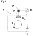
- the method is used in a device for controlling the air volume flow Q in a room section R.
- This comprises at least one temperature sensor 10 for measuring the temperatures in a spatial step R.
- This is designed such that it measures the temperature several times, in certain time intervals of length T and the values can transmit an evaluation unit 20.
- the transmission can be done wired or wirelessly (for example by radio).
- the device for controlling the air volume flow Q comprises an evaluation unit 20, which is designed such that it can be calculated from the temperature data calculate the value of thermal convection Q TH . Furthermore, it can compare this value with a programmed reference value Q Ref and transmit a signal to a control unit 30 as a function of the ratio of these values.
- the transmission can be wired or wireless (eg by radio) done.
- the sensor 10 may also comprise a time measuring means.
- the evaluation unit 20 comprises a time-measuring means and is designed such that it can initiate a measurement by the temperature sensor 10 at certain points in time (eg by a radio signal).
- the evaluation unit 20 and the control unit 30 can be located both inside and outside the room section R.
- the device comprises a further or a plurality of further temperature sensors, so that the temperature can be measured in a subdivision of the space section R into a plurality of spatial regions in each spatial region.
- the Prandtl number Pr> 0, the Nusselt number Nu> 0, a correction factor Re> 0 proportional to the Reynolds number, a geometric parameter ⁇ > 0 and the Rayleigh number Ra occur. All these parameters are dimensionless.
- the Rayleigh number represents the size, which can be changed by temperature differences between floor and ceiling of the room and in turn has direct influence on Nu and Re.
- This system of three non-linear differential equations of the first order has the same structure as the famous Lorenz system, which is a prime example of chaotic dynamics and originates from the modeling of convection in the Earth's atmosphere.
- the model thus offers some flow phenomena as a function of the Reynold number.
- the value of this model lies precisely in the revelation of these possibilities and not in the identification of the areas where the phenomena are to be expected, although here, too, a good match has been found.
- a disadvantage of the model is the reduction to two spatial directions, which can be remedied, however, by including an analogous description of a second flow roller transversely to the first in the model and coupling the two roller movements (3D model). There is little change in the way the movement is analyzed, and the examinations only become more complex.
Landscapes
- Engineering & Computer Science (AREA)
- Chemical & Material Sciences (AREA)
- Combustion & Propulsion (AREA)
- Mechanical Engineering (AREA)
- General Engineering & Computer Science (AREA)
- Life Sciences & Earth Sciences (AREA)
- Atmospheric Sciences (AREA)
- Physics & Mathematics (AREA)
- Fluid Mechanics (AREA)
- Air Conditioning Control Device (AREA)
Priority Applications (1)
| Application Number | Priority Date | Filing Date | Title |
|---|---|---|---|
| EP16175605.1A EP3260787A1 (fr) | 2016-06-22 | 2016-06-22 | Procede destine au reglage d'un debit d'air |
Applications Claiming Priority (1)
| Application Number | Priority Date | Filing Date | Title |
|---|---|---|---|
| EP16175605.1A EP3260787A1 (fr) | 2016-06-22 | 2016-06-22 | Procede destine au reglage d'un debit d'air |
Publications (1)
| Publication Number | Publication Date |
|---|---|
| EP3260787A1 true EP3260787A1 (fr) | 2017-12-27 |
Family
ID=56368788
Family Applications (1)
| Application Number | Title | Priority Date | Filing Date |
|---|---|---|---|
| EP16175605.1A Withdrawn EP3260787A1 (fr) | 2016-06-22 | 2016-06-22 | Procede destine au reglage d'un debit d'air |
Country Status (1)
| Country | Link |
|---|---|
| EP (1) | EP3260787A1 (fr) |
Cited By (1)
| Publication number | Priority date | Publication date | Assignee | Title |
|---|---|---|---|---|
| CN114096078A (zh) * | 2021-11-25 | 2022-02-25 | 四川九洲电器集团有限责任公司 | 不耐高温器件的印制板保护罩制备方法、保护罩及应用 |
Citations (2)
| Publication number | Priority date | Publication date | Assignee | Title |
|---|---|---|---|---|
| DE19654542A1 (de) * | 1996-12-27 | 1998-07-02 | Albert Bauer | Klimatisierungsvorrichtung |
| WO2009109056A1 (fr) * | 2008-03-07 | 2009-09-11 | Belimo Holding Ag | Dispositif de mesure et de régulation d'un débit volumique dans un tube d'aération |
-
2016
- 2016-06-22 EP EP16175605.1A patent/EP3260787A1/fr not_active Withdrawn
Patent Citations (3)
| Publication number | Priority date | Publication date | Assignee | Title |
|---|---|---|---|---|
| DE19654542A1 (de) * | 1996-12-27 | 1998-07-02 | Albert Bauer | Klimatisierungsvorrichtung |
| DE19654542C2 (de) | 1996-12-27 | 2000-08-17 | Albert Bauer | Klimatisierungsvorrichtung |
| WO2009109056A1 (fr) * | 2008-03-07 | 2009-09-11 | Belimo Holding Ag | Dispositif de mesure et de régulation d'un débit volumique dans un tube d'aération |
Non-Patent Citations (1)
| Title |
|---|
| RECKNAGEL; SPRENGER; SCHRAMEK: "Heizung und Klimatechnik", vol. 1043, 1997, OLDENBURG VERLAG MÜNCHEN WIEN S., pages: 1044 |
Cited By (2)
| Publication number | Priority date | Publication date | Assignee | Title |
|---|---|---|---|---|
| CN114096078A (zh) * | 2021-11-25 | 2022-02-25 | 四川九洲电器集团有限责任公司 | 不耐高温器件的印制板保护罩制备方法、保护罩及应用 |
| CN114096078B (zh) * | 2021-11-25 | 2023-07-25 | 四川九洲电器集团有限责任公司 | 不耐高温器件的印制板保护罩制备方法、保护罩及应用 |
Similar Documents
| Publication | Publication Date | Title |
|---|---|---|
| EP2874039B1 (fr) | Procédé de commande pour un système de transmission de chaleur et système de transmission de chaleur de ce type | |
| DE69101216T2 (de) | Verfahren und vorrichtung zur regelung der luftmenge in einem rohrleitungsnetz. | |
| DE69518499T2 (de) | Regelung der Antriebsmaschine einer verteilten Klimaanlage | |
| DE69706986T2 (de) | Zugehörigkeitsfunktionen ändernder adaptiver fuzzy-regler | |
| EP1936290B1 (fr) | Procédé et dispositif destinés à la détection de l'état hydraulique d'une installation de chauffage | |
| EP2870414B1 (fr) | Procédé pour le fonctionnement d'un échangeur thermique ainsi qu'installation hvac pour la réalisation du procédé | |
| DE102020109299B4 (de) | Verfahren zum Steuern einer Klimatisierungseinrichtung für ein Kraftfahrzeug und Klimatisierungseinrichtung damit | |
| WO2008025453A1 (fr) | Procédé pour faire fonctionner un réseau de tuyauterie | |
| DE102015217177A1 (de) | Transiente TBS-Berechnung des Gesamtfahrzeugs, Standardlastfälle und Nachheizen | |
| CH700963B1 (de) | Computerimplementiertes Verfahren und System zur automatischen Überwachung und Darstellung eines energieeffizienten Betriebs von gebäudetechnischen Anlagen. | |
| DE102014224489A1 (de) | Verfahren einer Klimatisierungseinrichtung, Klimatisierungseinrichtung | |
| DE112011105708T5 (de) | Management der Bereitstellung einer Luftströmung | |
| EP3366925A1 (fr) | Procédé de réglage fonctionnel d'un groupe motopompe ainsi que l'agencement d'un groupe motopompe et d'une électronique destiné à la mise en oeuvre dudit procédé | |
| EP2890936B1 (fr) | Procédé de réglage d'un dispositif de ventilation par couches en fonction des besoins et dispositif de ventilation par couches | |
| EP2626754A1 (fr) | Environnement de simulation pour une automatisation de bâtiments | |
| EP3267629B1 (fr) | Système d'analyse automatique et optimisation des systèmes d'automatisation de bâtiment | |
| DE102020000843A1 (de) | System zur Temperatur-Regelung eines Raums sowie bewegliches Gefährt mit einem Raum und einem System | |
| EP2009536A1 (fr) | Procédé et dispositif destinés à l'installation de la réserve de puissance de chauffe | |
| WO2019001683A1 (fr) | Procédé et dispositif de surveillance d'un échangeur de chaleur | |
| DE102018217661A1 (de) | Verfahren zum Bestimmen eines Schaltzustands eines Ventils und Elektromagnetventilanordnung | |
| EP4182762B1 (fr) | Dispositif de commande de soupapepour une installation de traitement et procédé de diagnostic correspondant | |
| EP1936454A1 (fr) | Unité de commande pour commander au moins un consommateur | |
| DE102014109949B4 (de) | Computerimplementiertes Verfahren zur Beurteilung eines energieeffizienten Betriebs einer gebäudetechnischen Anlage | |
| EP3976404B1 (fr) | Procédé de commande de dispositif de climatisation | |
| EP3009908B1 (fr) | Procédé et agencement de dispositif destinés à enregistrer, évaluer et influencer la répartition de la distribution des énergies de chauffage au sein d'une enveloppe de bâtiment |
Legal Events
| Date | Code | Title | Description |
|---|---|---|---|
| PUAI | Public reference made under article 153(3) epc to a published international application that has entered the european phase |
Free format text: ORIGINAL CODE: 0009012 |
|
| STAA | Information on the status of an ep patent application or granted ep patent |
Free format text: STATUS: THE APPLICATION HAS BEEN PUBLISHED |
|
| AK | Designated contracting states |
Kind code of ref document: A1 Designated state(s): AL AT BE BG CH CY CZ DE DK EE ES FI FR GB GR HR HU IE IS IT LI LT LU LV MC MK MT NL NO PL PT RO RS SE SI SK SM TR |
|
| AX | Request for extension of the european patent |
Extension state: BA ME |
|
| STAA | Information on the status of an ep patent application or granted ep patent |
Free format text: STATUS: REQUEST FOR EXAMINATION WAS MADE |
|
| 17P | Request for examination filed |
Effective date: 20180627 |
|
| RBV | Designated contracting states (corrected) |
Designated state(s): AL AT BE BG CH CY CZ DE DK EE ES FI FR GB GR HR HU IE IS IT LI LT LU LV MC MK MT NL NO PL PT RO RS SE SI SK SM TR |
|
| STAA | Information on the status of an ep patent application or granted ep patent |
Free format text: STATUS: EXAMINATION IS IN PROGRESS |
|
| 17Q | First examination report despatched |
Effective date: 20200710 |
|
| STAA | Information on the status of an ep patent application or granted ep patent |
Free format text: STATUS: THE APPLICATION IS DEEMED TO BE WITHDRAWN |
|
| 18D | Application deemed to be withdrawn |
Effective date: 20210121 |