EP3260795B1 - Dispositif d'appareil de chauffage - Google Patents
Dispositif d'appareil de chauffage Download PDFInfo
- Publication number
- EP3260795B1 EP3260795B1 EP16175280.3A EP16175280A EP3260795B1 EP 3260795 B1 EP3260795 B1 EP 3260795B1 EP 16175280 A EP16175280 A EP 16175280A EP 3260795 B1 EP3260795 B1 EP 3260795B1
- Authority
- EP
- European Patent Office
- Prior art keywords
- water
- heater device
- control unit
- intended
- unit
- Prior art date
- Legal status (The legal status is an assumption and is not a legal conclusion. Google has not performed a legal analysis and makes no representation as to the accuracy of the status listed.)
- Active
Links
Images

Classifications
-
- F—MECHANICAL ENGINEERING; LIGHTING; HEATING; WEAPONS; BLASTING
- F24—HEATING; RANGES; VENTILATING
- F24H—FLUID HEATERS, e.g. WATER OR AIR HEATERS, HAVING HEAT-GENERATING MEANS, e.g. HEAT PUMPS, IN GENERAL
- F24H1/00—Water heaters, e.g. boilers, continuous-flow heaters or water-storage heaters
- F24H1/10—Continuous-flow heaters, i.e. heaters in which heat is generated only while the water is flowing, e.g. with direct contact of the water with the heating medium
- F24H1/12—Continuous-flow heaters, i.e. heaters in which heat is generated only while the water is flowing, e.g. with direct contact of the water with the heating medium in which the water is kept separate from the heating medium
- F24H1/124—Continuous-flow heaters, i.e. heaters in which heat is generated only while the water is flowing, e.g. with direct contact of the water with the heating medium in which the water is kept separate from the heating medium using fluid fuel
-
- F—MECHANICAL ENGINEERING; LIGHTING; HEATING; WEAPONS; BLASTING
- F24—HEATING; RANGES; VENTILATING
- F24D—DOMESTIC- OR SPACE-HEATING SYSTEMS, e.g. CENTRAL HEATING SYSTEMS; DOMESTIC HOT-WATER SUPPLY SYSTEMS; ELEMENTS OR COMPONENTS THEREFOR
- F24D19/00—Details
- F24D19/10—Arrangement or mounting of control or safety devices
- F24D19/1006—Arrangement or mounting of control or safety devices for water heating systems
- F24D19/1066—Arrangement or mounting of control or safety devices for water heating systems for the combination of central heating and domestic hot water
-
- F—MECHANICAL ENGINEERING; LIGHTING; HEATING; WEAPONS; BLASTING
- F24—HEATING; RANGES; VENTILATING
- F24D—DOMESTIC- OR SPACE-HEATING SYSTEMS, e.g. CENTRAL HEATING SYSTEMS; DOMESTIC HOT-WATER SUPPLY SYSTEMS; ELEMENTS OR COMPONENTS THEREFOR
- F24D3/00—Hot-water central heating systems
- F24D3/10—Feed-line arrangements, e.g. providing for heat-accumulator tanks, expansion tanks ; Hydraulic components of a central heating system
- F24D3/1083—Filling valves or arrangements for filling
-
- F—MECHANICAL ENGINEERING; LIGHTING; HEATING; WEAPONS; BLASTING
- F24—HEATING; RANGES; VENTILATING
- F24H—FLUID HEATERS, e.g. WATER OR AIR HEATERS, HAVING HEAT-GENERATING MEANS, e.g. HEAT PUMPS, IN GENERAL
- F24H15/00—Control of fluid heaters
- F24H15/10—Control of fluid heaters characterised by the purpose of the control
- F24H15/14—Cleaning; Sterilising; Preventing contamination by bacteria or microorganisms, e.g. by replacing fluid in tanks or conduits
-
- F—MECHANICAL ENGINEERING; LIGHTING; HEATING; WEAPONS; BLASTING
- F24—HEATING; RANGES; VENTILATING
- F24H—FLUID HEATERS, e.g. WATER OR AIR HEATERS, HAVING HEAT-GENERATING MEANS, e.g. HEAT PUMPS, IN GENERAL
- F24H15/00—Control of fluid heaters
- F24H15/20—Control of fluid heaters characterised by control inputs
-
- F—MECHANICAL ENGINEERING; LIGHTING; HEATING; WEAPONS; BLASTING
- F24—HEATING; RANGES; VENTILATING
- F24H—FLUID HEATERS, e.g. WATER OR AIR HEATERS, HAVING HEAT-GENERATING MEANS, e.g. HEAT PUMPS, IN GENERAL
- F24H15/00—Control of fluid heaters
- F24H15/30—Control of fluid heaters characterised by control outputs; characterised by the components to be controlled
- F24H15/305—Control of valves
- F24H15/31—Control of valves of valves having only one inlet port and one outlet port, e.g. flow rate regulating valves
-
- F—MECHANICAL ENGINEERING; LIGHTING; HEATING; WEAPONS; BLASTING
- F24—HEATING; RANGES; VENTILATING
- F24H—FLUID HEATERS, e.g. WATER OR AIR HEATERS, HAVING HEAT-GENERATING MEANS, e.g. HEAT PUMPS, IN GENERAL
- F24H15/00—Control of fluid heaters
- F24H15/30—Control of fluid heaters characterised by control outputs; characterised by the components to be controlled
- F24H15/395—Information to users, e.g. alarms
-
- F—MECHANICAL ENGINEERING; LIGHTING; HEATING; WEAPONS; BLASTING
- F24—HEATING; RANGES; VENTILATING
- F24H—FLUID HEATERS, e.g. WATER OR AIR HEATERS, HAVING HEAT-GENERATING MEANS, e.g. HEAT PUMPS, IN GENERAL
- F24H15/00—Control of fluid heaters
- F24H15/40—Control of fluid heaters characterised by the type of controllers
- F24H15/414—Control of fluid heaters characterised by the type of controllers using electronic processing, e.g. computer-based
-
- F—MECHANICAL ENGINEERING; LIGHTING; HEATING; WEAPONS; BLASTING
- F24—HEATING; RANGES; VENTILATING
- F24H—FLUID HEATERS, e.g. WATER OR AIR HEATERS, HAVING HEAT-GENERATING MEANS, e.g. HEAT PUMPS, IN GENERAL
- F24H9/00—Details
- F24H9/12—Arrangements for connecting heaters to circulation pipes
- F24H9/13—Arrangements for connecting heaters to circulation pipes for water heaters
Definitions
- the DE 29924189 U1 discloses a hose connection valve with remote control for two solenoid valves with a filling hose for filling or emptying a connected to a piping system container system, wherein a filling hose integrated in the filling and emptying has two radio controlled solenoid valves, the container system selectively connectable to the piping system or an emptying system do.
- the EP 1832816 A2 discloses a hydraulic device for water heating systems having a body comprising an inlet channel and a first outlet channel and a second outlet channel, and with on / off means for interrupting a fluid flow.
- the on / off means comprise at least two on / off devices which can influence a fluid flow in the second outlet channel. This allows automatic or semi-automatic filling of hydraulic equipment or systems.
- the DE 19632604 A1 discloses a hydraulic assembly for a combined heating water and Sanitärwasserstrom, wherein in the hydraulic assembly a Filling device for filling the Schumachernikanks with water as an interchangeable unit is integrated.
- the invention relates to a heater device, in particular a combi boiler device, with at least one internal heating circuit, which is provided to form part of a Monabonikanks for circulating heating water in at least one connected state, and with at least one water exchange unit, which is intended to the central heating circuit in particular automated, if necessary, at least partially, in particular completely emptied and, if necessary, at least partially, in particular completely filled with fresh water.
- the heater device has a control unit which is provided to operate the water exchange unit in dependence on a degree of contamination of the heating water.
- a “heater device” should in particular be understood to mean a component, in particular a functional component, in particular a design and / or functional component of a heater, in particular a boiler, preferably a combi boiler.
- the heater device has at least one, in particular activated as needed, heating unit.
- a "heating unit” is to be understood as meaning in particular a unit which is intended to convert energy, in particular electrical energy, bioenergy and / or preferably fossil energy, for example chemical binding energy of a particularly fossil fuel, in particular directly into heat, and in particular a fluid, preferably water, supply.
- the heating unit comprises at least one heating module and advantageously at least one primary heat exchanger.
- the heating module can in particular be designed as an electric heater and / or advantageously as a burner, in particular as an oil burner and particularly preferably as a gas burner and advantageously has a thermal connection with the primary heat exchanger for heating the fluid.
- the primary heat exchanger comprises at least one supply line for a fluid, in particular unheated and / or to be heated, and in particular at least one outlet for a fluid heated in particular by means of the heating module.
- the water exchange unit is intended to "empty" the central heating circuit should be understood in this context that the water exchange unit is intended to remove heating water from the central heating, for example, by filling the corresponding volume with air and / or by fresh water.
- the internal heating circuit comprises the primary heat exchanger.
- the heater device at least one inlet and at least one outlet, which are intended to be connected to a line system, for example, a building.
- a line system for example, a building.
- the power system and the internal heating circuit together make up the central heating circuit.
- the heating water circulates through the line system, the inlet, the heating unit, the primary heat exchanger and the drain.
- the heater device comprises at least one secondary heat exchanger, which is connected in parallel in particular to the primary heat exchanger.
- the secondary heat exchanger is intended to be connected to a service water system for service water.
- the secondary heat exchanger is provided to extract heat from the heating water and to supply heat to the service water.
- control unit is to be understood as meaning, in particular, an electrical and / or electronic unit having at least one control electronics.
- a “control electronics” is to be understood as meaning a unit having a computing unit and a memory unit as well as an operating, control and / or regulating program stored in the memory unit, which is provided in particular for execution by the computing unit.
- the degree of contamination is advantageously dependent on a concentration of suspended particles and / or particles, in particular of different sizes and / or salts and / or corrosion residues and / or bacteria and / or in particular organic impurities and / or other contaminating substances of the heating water.
- the control unit is provided to initiate a water exchange of the heating water by means of at least one emptying and by means of at least one particular subsequent filling of the central heating by the water exchange unit.
- the control unit is provided to initiate the water exchange of the heating water, if the degree of contamination exceeds a particular selectable and / or predefined and / or stored pollution limit.
- the contamination limit value corresponds to a degree of contamination which is above a degree of contamination of the fresh water and / or above a degree of contamination of tap water.
- the heater device advantageous properties can be achieved with respect to an operation of a heater device. Furthermore, in particular pollution-related failures can be reliably avoided and / or a permanent and / or error-free operation can be made possible. Advantageously, a high degree of user comfort can be achieved. In addition, a reliable maintenance and / or low pollution can be achieved. Furthermore, a heater device can be provided, which automatically adapts to a degree of contamination of a heating water. Advantageously, a too early and / or too late replacement of heating water can be avoided.
- the heater device has at least one sensor unit which is provided for detecting the degree of contamination.
- the sensor unit is at least partially disposed in the internal heating circuit.
- the sensor unit can be flowed through by the heating water and / or designed to flow through.
- the sensor unit is provided to generate at least one sensor signal representing the degree of soiling.
- the sensor unit comprises at least one turbidity sensor.
- the haze sensor for turbidity measurement is at least up to 3000 NTU (Nephelometric Turbidity Unit, is a turbidity measurement unit used in water treatment in liquids), preferably at least up to 5000 NTU, and more preferably at least up to 10000 NTU designed.
- an operation of the turbidity sensor is based at least in part on at least one transmitted light and / or at least one scattered light method. As a result, advantageously a degree of contamination can be reliably determined.
- control unit is provided to query at least one sensor signal of the sensor unit in at least one specific polling clocking.
- control unit is intended to to query the sensor signal of the sensor unit at certain time intervals.
- the control unit can be provided to query the sensor signal of the sensor unit every 1 s or every 10 s or every 1 min or every 10 min or every 1 h or after every 24 h or at larger, smaller or intervening intervals ,
- an operating mode is conceivable in which the control unit interrogates the sensor signal in varying, in particular adaptive, intervals. For example, a next waiting time until a next polling of the sensor signal may depend on a detected contamination level and / or on a detected contamination level profile.
- control unit is provided to set the query timing as a function of a current degree of contamination.
- control unit is preferably provided to increase the polling timing with increasing degree of contamination with time and / or to reduce polling timing when the degree of contamination returns and / or to reduce the polling timing while maintaining the uncritical degree of contamination.
- control unit is provided to allow an input of the query timing by a user.
- the control unit comprises at least one user interface, which includes, for example, at least one touchpad and / or at least one switch and / or at least one dial button and / or at least one display and / or at least one voice recognition interface and / or at least one wireless interface for connection to a mobile device such as For example, a smartphone and / or a tablet PC and / or a data glasses includes.
- a mobile device such as For example, a smartphone and / or a tablet PC and / or a data glasses includes.
- the control unit is provided to allow an input of an expected fouling rate by a user and in particular to determine a suitable polling timing from an inputted expected fouling rate.
- control unit may be provided with at least one further, in particular a plurality of further parameters such as, for example, a water hardness and / or a pH and / or a salt concentration and / or an age of the line system and / or a region and / or or an age of the heater device or the like by a user to query and / or use to set the polling timing.
- a further parameter such as, for example, a water hardness and / or a pH and / or a salt concentration and / or an age of the line system and / or a region and / or or an age of the heater device or the like by a user to query and / or use to set the polling timing.
- the water exchange unit has a drain valve which can be activated by the control unit.
- the drain valve is designed as a solenoid valve.
- the drain valve is connected to at least one drain, which is provided for connection to a sewer line.
- the drain valve is provided for draining the central heating circuit.
- the water exchange unit comprises a controllable by the control unit filling valve.
- the filling valve is designed as a solenoid valve.
- the filling valve is connected to at least one fresh water connection, which is provided for connection to a fresh water line.
- the filling valve is provided for filling the central heating circuit, in particular in its at least partially emptied and / or at least partially pressure-relieved state with fresh water.
- hot water to be exchanged during the water exchange is pressed at least partially out of the central heating circuit by incoming fresh water. In this way, advantageously, an automated filling of a heating circuit can be made possible.
- control unit is provided to simultaneously open the drain valve and the filling valve in at least one rinse mode.
- fresh water is flushed through the central heating circuit in the purge mode.
- control unit in the water exchange of the heating water of the rinse mode via a certain, in particular by a user selectable and / or executed by a degree of pollution and / or executed by the control unit, in particular at least on the basis of the degree of contamination, for example over a period of at least 10 seconds or at least 1 minute or at least 5 minutes or at least 10 minutes or at least 1 hour or at least 5 hours for another, especially longer or shorter, period.
- control unit is provided to first close the drain valve after performing the purge mode in order to achieve a pressure build-up in the central heating circuit.
- control unit is provided in the water exchange of the heating water to actuate the filling valve and / or the drain valve in dependence on a total volume of the central heating circuit and / or a pressure and / or a flow rate of the fresh water line.
- the control unit provide at least one service information for a user in at least one service mode.
- the information advantageously comprises at least one warning and / or at least one alarm and / or at least one service code.
- the service information is provided to inform a user of an occurrence of a problem state, for example, a high degree of contamination and / or too frequent a need for water exchange of the heating water.
- the service information includes a frequency of water exchange.
- control unit is provided to provide further information for a user, for example, a value and / or a time profile of the degree of contamination and / or a water pressure and / or the query timing and / or a time of last water exchange of the heating water and / or several times of the last water exchanges of the heating water and / or other operating parameters of the heater device. It is also conceivable that the control unit is provided to inform a user about a necessary and / or forthcoming water exchange and / or to have this confirmed by the user.
- the control unit is provided to switch to a service mode when a limit value of a frequency of a water exchange is exceeded.
- the threshold may be 1 / day or 1 / week or 1 / month, or any other suitable, especially greater, smaller, or intermediate value. This advantageously allows a user to be alerted if low heating water quality and / or high heating water contamination causes a need for frequent water exchange.
- the control unit is provided to transmit at least one piece of information to at least one external device, in particular by means of at least one data connection, such as an internet.
- the external device is designed as a mobile device and / or a server and / or a company headquarters and / or a service center.
- the external device is designed as a smartphone or a tablet PC or a data glasses or a computer of the user.
- the external device is part of a customer service.
- the information contains at least one operating parameter of the heater device and in particular the degree of soiling and / or the frequency of the water exchange.
- the information is provided to allow monitoring of the heater device and in particular its operation by the user and / or customer service and / or customer service and / or a corporate office.
- advantageously operating parameters of a heater device can be provided comfortably and / or centrally and / or quickly retrievable.
- a reliable and / or comfortable and / or low-maintenance operation may further with a heating system with at least one heater device according to the invention and with at least one Monaxialnikank, partially is formed by the internal heating circuit of the heater device, can be achieved.
- the invention relates to a method for operating a heating system, in particular with a heater device according to the invention, with at least one Primazing Vietnamese Hops for circulating heating water, the Monsymonashams is automatically emptied as required, depending on a degree of contamination of the heating water and filled with fresh water.
- a heater device can be achieved by the method according to the invention. Furthermore, in particular pollution-related failures can be reliably avoided and / or a permanent and / or error-free operation can be made possible. Advantageously, a high degree of user comfort can be achieved. In addition, a reliable maintenance and / or low pollution can be achieved. Furthermore, a heater device can be provided, which automatically adapts to a degree of contamination of a heating water. Advantageously, a too early and / or too late replacement of heating water can be avoided.
- the heater device according to the invention should not be limited to the application and embodiment described above.
- the heater device according to the invention may have a number deviating from a number of individual elements, components and units specified herein.
- the FIG. 1 shows a heater 30 with a heater device 10 in a perspective view.
- the heater 30 is designed as a combi boiler.
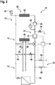
- the FIG. 2 shows a schematic representation of a heating system 32 with the heater device 10.
- the heating system 32 includes a central heating circuit 14 for circulating heating water.
- the heater device 10 has an internal heating circuit 12, which is provided to form part of the central heating circuit 14 in at least one connected state. In the present case, the central heating circuit 14 is partially formed by the internal heating circuit 12 of the heater device 10.
- the heater device 10 has a water exchange unit 16, which is provided to empty the central heating circuit 14, if necessary, and to fill with fresh water, if necessary. Furthermore, the heater device 10 has a control unit 18, which is provided to operate the water exchange unit 16 in response to a degree of contamination of the heating water.
- the heating system 32 comprises a line system 34, which in the present case is designed as a pipeline system of a building, not shown.
- the heater apparatus 10 has a primary heat exchanger 36, which is part of a heating unit 38, which is provided for generating a heat for heating the heating water by means of a heat exchange in the primary heat exchanger 36. Further, in the present case, the heater apparatus 10 has a secondary heat exchanger 40. The secondary heat exchanger 40 has ports 42, 44, which are provided for connection to a service water system 46 for service water. The secondary heat exchanger 40 is connected in the present case parallel to the primary heat exchanger 36. The secondary heat exchanger 40 is provided to extract heat from the heating water and to supply heat to the service water. In addition, in the present case, the heater device 10 has a bypass line 48 with a bypass valve 50.
- a heater device 10 according to the invention does not comprise such a bypass line and / or such a bypass valve.
- the heater device 10 in the present case comprises an automatic vent valve 52, the presence of which is also to be understood as completely optional.
- the heater device 10 in the present case comprises an equally optional pressure equalization valve 54.
- the heater device 10 has a pump 56 which is provided for conveying the heating water through the central heating circuit 14.
- the heater apparatus 10 preferably has a pressure sensor 58 provided for detecting a pressure of the heating water.
- the heater device 10 has a sensor unit 20, which is provided for detecting the degree of contamination.
- the sensor unit 20 has a turbidity sensor 22.
- the turbidity sensor 22 is formed in the present case as an optical turbidity sensor.
- the sensor unit 20 is arranged in the central heating circuit 14.
- the sensor unit 20 is formed by the heating water permeable.
- the sensor unit 20 is provided, at least to provide a sensor signal to the control unit 18.
- the sensor signal comprises in the present case a representation of the degree of contamination.
- the control unit 18 is intended to trigger a water exchange of the heating water by means of emptying and by means of a subsequent filling of the central heating circuit 14 by the water exchange unit 16.
- the control unit 18 is intended to trigger the water exchange, if the degree of pollution exceeds a specified limit.
- the control unit 18 is provided to query the sensor signal of the sensor unit 20 in a specific polling timing. In the present case, the control unit 18 queries the sensor signal in time intervals of a few seconds. However, as stated above, other, in particular varying, query clock rates are also conceivable.
- the control unit 18 is provided to allow input of the polling timing by a user.
- the control unit 18 comprises a user interface 60 (see. Fig. 1 ).
- the user interface 60 is designed as an input area with a display. But it is also conceivable, for example, a user interface with a touch screen.
- a user can also enter information about a state of the line system 34, an available fresh water or its quality, an expected heating and / or water requirement and the like via the user interface 60.
- the control unit 18 is provided in the present case, based on these user inputs to produce a proposal for a query timing, which can be confirmed or adapted by the user. But it is also conceivable a direct input of a query clocking by a user or a direct setting a query clock from a corresponding control unit.
- the water exchange unit 16 has a controllable by the control unit 18 drain valve 24.
- the drain valve 24 is formed in the present case as a solenoid valve.
- the water exchange unit 16 has a controllable by the control unit 18 filling valve 26.
- the filling valve 26 is in present case designed as a solenoid valve.
- the control unit 18 opens the drain valve 24 to drain the heating water from the central heating circuit 14. Subsequently, the control unit 18 closes the drain valve 24 and opens the filling valve 26 to direct fresh water into the central heating circuit 14 as new heating water.
- the control unit 18 provides at least one service information for the user in at least one service mode.
- the service information includes a warning message that water replacement is too often necessary.
- the service information in the present case comprises a service code that the user can use when contacting a customer service.
- the control unit 18 is intended to switch to a service mode when the limit of a frequency of water exchange is exceeded. In the present case, the control unit 18 changes to the service mode when a water exchange more often than every two weeks is necessary. A user is then informed by means of the service information about an occurrence of a problem. But there are also any other limits conceivable.
- the control unit 18 is intended to transmit at least one piece of information to an external device 28 (cf. Fig. 1 ).
- the external device 28 is designed as a service center. Further, in the present case, the information is transmitted to the external device 28 via an Internet.
- the information in the present case includes various operating parameters of the heater device 10, such as a current degree of soiling of the heating water, an operating time, a heating water temperature, a frequency of water exchange, and the like.
- a control unit is provided to transmit information to a, in particular mobile, external device of a user, such as to a smartphone, a tablet PC, a data glasses or the like, wherein the information may also include, for example, different operating parameters of a corresponding heater device.
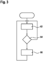
- the FIG. 3 shows a schematic flow diagram of a method for operating the heating system 32.
- a measuring step 62 the degree of contamination of the heating water is determined.
- a comparison step 64 the degree of contamination is compared with a specified limit value. If the degree of contamination is below the limit, the degree of contamination of the heating water is determined again and advantageously queried by the control unit 18 with a specific query timing. If the degree of contamination exceeds the limit value, the central heating circuit 14 is automatically emptied and filled with fresh water in an exchange step 66.
- an internal heating circuit has at least one filter unit which is provided for filtering a circulating heating water.
- basically a different programming of a control unit depending on a region in which a corresponding heater device is used and / or a model or the like is conceivable, for example with respect to a behavior of the control unit in a user information.
- a manual filling valve is used instead of an automatic filling valve. In this case, a corresponding control unit is advantageously provided to prompt a user, if necessary, to actuate the manual filling valve.
Landscapes
- Engineering & Computer Science (AREA)
- Physics & Mathematics (AREA)
- Thermal Sciences (AREA)
- Chemical & Material Sciences (AREA)
- Combustion & Propulsion (AREA)
- Mechanical Engineering (AREA)
- General Engineering & Computer Science (AREA)
- Fluid Mechanics (AREA)
- Computer Hardware Design (AREA)
- Steam Or Hot-Water Central Heating Systems (AREA)
Claims (13)
- Dispositif d'appareil de chauffage (10), en particulier dispositif de chaudière combinée, avec au moins un circuit de chauffage interne (12), qui est prévu pour former, dans au moins un état raccordé, une partie d'un circuit de chauffage central (14) pour de l'eau chaude en circulation, et avec au moins une unité d'échange d'eau (16), qui est prévue pour vider au moins partiellement au besoin le circuit de chauffage central (14) et le remplir au moins partiellement au besoin avec de l'eau fraîche, avec une unité de commande, caractérisé en ce que l'unité de commande est prévue pour actionner l'unité d'échange d'eau (16) en fonction d'un degré d'encrassement de l'eau chaude.
- Dispositif d'appareil de chauffage (10) selon la revendication 1, caractérisé par au moins une unité de capteur (20), qui est prévue pour la détection du degré d'encrassement.
- Dispositif d'appareil de chauffage (10) selon la revendication 2, caractérisé en ce que l'unité de capteur (20) comprend au moins un détecteur de turbidité (22).
- Dispositif d'appareil de chauffage (10) selon une revendication 2 ou 3, caractérisé en ce que l'unité de commande (18) est prévue pour interroger au moins un signal de capteur de l'unité de capteur (20) avec au moins une cadence d'interrogation déterminée.
- Dispositif d'appareil de chauffage (10) selon la revendication 4, caractérisé en ce que l'unité de commande (18) est prévue pour permettre une entrée de la cadence d'interrogation par un utilisateur.
- Dispositif d'appareil de chauffage (10) selon l'une quelconque des revendications précédentes, caractérisé en ce que l'unité d'échange d'eau (16) présente une soupape d'évacuation (24) pouvant être commandée par l'unité de commande (18).
- Dispositif d'appareil de chauffage (10) selon l'une quelconque des revendications précédentes, caractérisé en ce que l'unité d'échange d'eau (16) présente une soupape de remplissage (26) pouvant être commandée par l'unité de commande (18).
- Dispositif d'appareil de chauffage (10) selon l'une quelconque des revendications précédentes, caractérisé en ce que l'unité de commande (18) procure au moins une information de service pour un utilisateur dans au moins un mode de service.
- Dispositif d'appareil de chauffage (10) selon la revendication 8, caractérisé en ce que l'unité de commande (18) est prévue pour basculer dans le mode de service en cas de dépassement d'une valeur limite d'une fréquence d'un échange d'eau.
- Dispositif d'appareil de chauffage (10) selon l'une quelconque des revendications précédentes, caractérisé en ce que l'unité de commande (18) est prévue pour transmettre une information à au moins un dispositif extérieur (28).
- Appareil de chauffage (30), en particulier chaudière combinée, avec au moins un dispositif d'appareil de chauffage (10) selon l'une quelconque des revendications précédentes.
- Système de chauffage (32) avec au moins un dispositif d'appareil de chauffage (10) selon l'une quelconque des revendications 1 à 10 et avec au moins un circuit de chauffage central (14), qui est formé en partie par le circuit de chauffage interne (12) du dispositif d'appareil de chauffage (10).
- Procédé de conduite d'un système de chauffage (32), avec un dispositif d'appareil de chauffage (10) selon l'une quelconque des revendications 1 à 10, avec au moins un circuit de chauffage central (14) pour de l'eau chaude en circulation, dans lequel au besoin on vide et on remplit avec de l'eau fraîche le circuit de chauffage central de façon automatisée en fonction d'un degré d'encrassement de l'eau chaude.
Priority Applications (1)
| Application Number | Priority Date | Filing Date | Title |
|---|---|---|---|
| EP16175280.3A EP3260795B1 (fr) | 2016-06-20 | 2016-06-20 | Dispositif d'appareil de chauffage |
Applications Claiming Priority (1)
| Application Number | Priority Date | Filing Date | Title |
|---|---|---|---|
| EP16175280.3A EP3260795B1 (fr) | 2016-06-20 | 2016-06-20 | Dispositif d'appareil de chauffage |
Publications (2)
| Publication Number | Publication Date |
|---|---|
| EP3260795A1 EP3260795A1 (fr) | 2017-12-27 |
| EP3260795B1 true EP3260795B1 (fr) | 2019-08-21 |
Family
ID=56148223
Family Applications (1)
| Application Number | Title | Priority Date | Filing Date |
|---|---|---|---|
| EP16175280.3A Active EP3260795B1 (fr) | 2016-06-20 | 2016-06-20 | Dispositif d'appareil de chauffage |
Country Status (1)
| Country | Link |
|---|---|
| EP (1) | EP3260795B1 (fr) |
Families Citing this family (3)
| Publication number | Priority date | Publication date | Assignee | Title |
|---|---|---|---|---|
| TR201713789A2 (tr) * | 2017-09-18 | 2017-10-23 | Bosch Termoteknik Isitma ve Klima Sanayi Ticaret Anonim Sirketi | Bulaniklik sensörüne sahi̇p bi̇r su isitici ve bu su isiticinin çaliştirilmasi i̇çi̇n bi̇r yöntem |
| DE102018210071A1 (de) | 2018-06-21 | 2019-12-24 | Robert Bosch Gmbh | Heizgerät sowie Heizsystem mit einem Heizgerät |
| GB2586581B (en) * | 2019-08-07 | 2024-03-13 | Radisoft Ltd | Improvements in or relating to fluid measurement devices |
Family Cites Families (4)
| Publication number | Priority date | Publication date | Assignee | Title |
|---|---|---|---|---|
| DE19632604A1 (de) * | 1996-08-13 | 1998-02-19 | Wilo Gmbh | Befülleinrichtung für Hydraulikbaugruppe |
| DE29924189U1 (de) * | 1999-01-13 | 2002-04-04 | Zimmermann, Ulrich, 18109 Rostock | Füllschlauch mit funkgesteuerter Füllarmatur mit Fernbedienung |
| ITTO20060177A1 (it) * | 2006-03-09 | 2007-09-10 | Eltek Spa | Dispositivo idraulico, apparecchiatura idraulica, impianto idraulico e metodo per il suo utilizzo |
| GB2509714A (en) * | 2013-01-09 | 2014-07-16 | Intaco Ltd | Plumbing diverter component |
-
2016
- 2016-06-20 EP EP16175280.3A patent/EP3260795B1/fr active Active
Non-Patent Citations (1)
| Title |
|---|
| None * |
Also Published As
| Publication number | Publication date |
|---|---|
| EP3260795A1 (fr) | 2017-12-27 |
Similar Documents
| Publication | Publication Date | Title |
|---|---|---|
| EP3260795B1 (fr) | Dispositif d'appareil de chauffage | |
| WO2016192966A1 (fr) | Procédé de diagnostic d'une vanne à membrane, et système de diagnostic pour vanne à membrane | |
| DE102008005151A1 (de) | Vorrichtung und Verfahren zur Ermittlung eines Verkalkungszustands in einem elektrischen Haushaltsgerät | |
| DE102014012784A1 (de) | Verfahren und Vorrichtung zur Durchführung einer Integritätsprüfung eines Filterelements | |
| DE102008039667A1 (de) | Wasseraufbereitungsvorrichtung und -verfahren für eine Trinkwasseranlage insbesondere in einem Passagierflugzeug | |
| DE102015113886A1 (de) | Vorrichtung, System und Verfahren zum selbsttätigen Spülen mit Mehrfachventil | |
| DE112020002026T5 (de) | Verfahren zur automatischen reinigung von heizkesselrohren | |
| EP2908059A1 (fr) | Procédé de diagnostic d'une installation de chauffage doté d'au moins un échangeur thermique | |
| EP2667104A2 (fr) | Installation et procédé de chauffage d'eau potable | |
| DE102009027144A1 (de) | Vorrichtung zur Behandlung von Zulaufwasser für einen Wasserkreislauf | |
| WO2017114592A1 (fr) | Dispositif pour contrôler la réactivité d'un capteur en tenant compte du nouvel état | |
| DE102013020635B4 (de) | Warmwassergerät und Verfahren zum Betreiben eines Warmwassergerätes | |
| DE112020002027T5 (de) | System für die automatische reinigung von heizkesselrohren | |
| DE102019001743A1 (de) | Haushaltsgerät und zugehöriges Verfahren zum Steuern | |
| DE102013223857A1 (de) | Verfahren und Vorrichtung zur Erfassung der Eigenschaften eines Kochtopfes bezüglich Wärmeabnahme | |
| WO2023104866A1 (fr) | Détermination d'un titre hydrotimétrique croissant de l'eau | |
| EP3457034B1 (fr) | Chauffe-eau à capteur de turbidité et procédé de fonctionnement d'un tel chauffe-eau | |
| DE102016225408A1 (de) | Fluidvorrichtung und Verfahren zur Überwachung einer Fluidvorrichtung | |
| EP2846087B1 (fr) | Procédé de fonctionnement d'une chaudière à vapeur et dispositif destiné à l'exécution du procédé | |
| DE202016006759U1 (de) | Vorrichtung zur Aufbereitung von Heizungskreislaufwasser | |
| EP2280230A2 (fr) | Procédé de surveillance de l'état de salissure d'un échangeur thermique sur un appareil de chauffage | |
| AT516830B1 (de) | Spülmaschine | |
| DE102024106700A1 (de) | Wasserbehandlungsvorrichtung, wasserbehandlungssystem, betriebsverfahren | |
| Jusic et al. | Model based control of filter run time on potable water treatment plant | |
| DE102021109877B3 (de) | Hydraulikaggregat |
Legal Events
| Date | Code | Title | Description |
|---|---|---|---|
| PUAI | Public reference made under article 153(3) epc to a published international application that has entered the european phase |
Free format text: ORIGINAL CODE: 0009012 |
|
| STAA | Information on the status of an ep patent application or granted ep patent |
Free format text: STATUS: THE APPLICATION HAS BEEN PUBLISHED |
|
| AK | Designated contracting states |
Kind code of ref document: A1 Designated state(s): AL AT BE BG CH CY CZ DE DK EE ES FI FR GB GR HR HU IE IS IT LI LT LU LV MC MK MT NL NO PL PT RO RS SE SI SK SM TR |
|
| AX | Request for extension of the european patent |
Extension state: BA ME |
|
| STAA | Information on the status of an ep patent application or granted ep patent |
Free format text: STATUS: REQUEST FOR EXAMINATION WAS MADE |
|
| 17P | Request for examination filed |
Effective date: 20180627 |
|
| RBV | Designated contracting states (corrected) |
Designated state(s): AL AT BE BG CH CY CZ DE DK EE ES FI FR GB GR HR HU IE IS IT LI LT LU LV MC MK MT NL NO PL PT RO RS SE SI SK SM TR |
|
| GRAP | Despatch of communication of intention to grant a patent |
Free format text: ORIGINAL CODE: EPIDOSNIGR1 |
|
| STAA | Information on the status of an ep patent application or granted ep patent |
Free format text: STATUS: GRANT OF PATENT IS INTENDED |
|
| RIC1 | Information provided on ipc code assigned before grant |
Ipc: F24D 19/10 20060101ALI20190213BHEP Ipc: F24H 9/12 20060101ALI20190213BHEP Ipc: F24H 9/20 20060101ALI20190213BHEP Ipc: F24D 3/10 20060101ALI20190213BHEP Ipc: F24H 1/12 20060101AFI20190213BHEP |
|
| INTG | Intention to grant announced |
Effective date: 20190312 |
|
| GRAS | Grant fee paid |
Free format text: ORIGINAL CODE: EPIDOSNIGR3 |
|
| GRAA | (expected) grant |
Free format text: ORIGINAL CODE: 0009210 |
|
| STAA | Information on the status of an ep patent application or granted ep patent |
Free format text: STATUS: THE PATENT HAS BEEN GRANTED |
|
| AK | Designated contracting states |
Kind code of ref document: B1 Designated state(s): AL AT BE BG CH CY CZ DE DK EE ES FI FR GB GR HR HU IE IS IT LI LT LU LV MC MK MT NL NO PL PT RO RS SE SI SK SM TR |
|
| REG | Reference to a national code |
Ref country code: GB Ref legal event code: FG4D Free format text: NOT ENGLISH |
|
| REG | Reference to a national code |
Ref country code: CH Ref legal event code: EP |
|
| REG | Reference to a national code |
Ref country code: DE Ref legal event code: R096 Ref document number: 502016006159 Country of ref document: DE |
|
| REG | Reference to a national code |
Ref country code: AT Ref legal event code: REF Ref document number: 1170209 Country of ref document: AT Kind code of ref document: T Effective date: 20190915 |
|
| REG | Reference to a national code |
Ref country code: IE Ref legal event code: FG4D Free format text: LANGUAGE OF EP DOCUMENT: GERMAN |
|
| REG | Reference to a national code |
Ref country code: NL Ref legal event code: FP |
|
| REG | Reference to a national code |
Ref country code: LT Ref legal event code: MG4D |
|
| PG25 | Lapsed in a contracting state [announced via postgrant information from national office to epo] |
Ref country code: NO Free format text: LAPSE BECAUSE OF FAILURE TO SUBMIT A TRANSLATION OF THE DESCRIPTION OR TO PAY THE FEE WITHIN THE PRESCRIBED TIME-LIMIT Effective date: 20191121 Ref country code: BG Free format text: LAPSE BECAUSE OF FAILURE TO SUBMIT A TRANSLATION OF THE DESCRIPTION OR TO PAY THE FEE WITHIN THE PRESCRIBED TIME-LIMIT Effective date: 20191121 Ref country code: SE Free format text: LAPSE BECAUSE OF FAILURE TO SUBMIT A TRANSLATION OF THE DESCRIPTION OR TO PAY THE FEE WITHIN THE PRESCRIBED TIME-LIMIT Effective date: 20190821 Ref country code: PT Free format text: LAPSE BECAUSE OF FAILURE TO SUBMIT A TRANSLATION OF THE DESCRIPTION OR TO PAY THE FEE WITHIN THE PRESCRIBED TIME-LIMIT Effective date: 20191223 Ref country code: HR Free format text: LAPSE BECAUSE OF FAILURE TO SUBMIT A TRANSLATION OF THE DESCRIPTION OR TO PAY THE FEE WITHIN THE PRESCRIBED TIME-LIMIT Effective date: 20190821 Ref country code: LT Free format text: LAPSE BECAUSE OF FAILURE TO SUBMIT A TRANSLATION OF THE DESCRIPTION OR TO PAY THE FEE WITHIN THE PRESCRIBED TIME-LIMIT Effective date: 20190821 Ref country code: FI Free format text: LAPSE BECAUSE OF FAILURE TO SUBMIT A TRANSLATION OF THE DESCRIPTION OR TO PAY THE FEE WITHIN THE PRESCRIBED TIME-LIMIT Effective date: 20190821 |
|
| PG25 | Lapsed in a contracting state [announced via postgrant information from national office to epo] |
Ref country code: GR Free format text: LAPSE BECAUSE OF FAILURE TO SUBMIT A TRANSLATION OF THE DESCRIPTION OR TO PAY THE FEE WITHIN THE PRESCRIBED TIME-LIMIT Effective date: 20191122 Ref country code: AL Free format text: LAPSE BECAUSE OF FAILURE TO SUBMIT A TRANSLATION OF THE DESCRIPTION OR TO PAY THE FEE WITHIN THE PRESCRIBED TIME-LIMIT Effective date: 20190821 Ref country code: RS Free format text: LAPSE BECAUSE OF FAILURE TO SUBMIT A TRANSLATION OF THE DESCRIPTION OR TO PAY THE FEE WITHIN THE PRESCRIBED TIME-LIMIT Effective date: 20190821 Ref country code: ES Free format text: LAPSE BECAUSE OF FAILURE TO SUBMIT A TRANSLATION OF THE DESCRIPTION OR TO PAY THE FEE WITHIN THE PRESCRIBED TIME-LIMIT Effective date: 20190821 Ref country code: IS Free format text: LAPSE BECAUSE OF FAILURE TO SUBMIT A TRANSLATION OF THE DESCRIPTION OR TO PAY THE FEE WITHIN THE PRESCRIBED TIME-LIMIT Effective date: 20191221 Ref country code: LV Free format text: LAPSE BECAUSE OF FAILURE TO SUBMIT A TRANSLATION OF THE DESCRIPTION OR TO PAY THE FEE WITHIN THE PRESCRIBED TIME-LIMIT Effective date: 20190821 |
|
| PG25 | Lapsed in a contracting state [announced via postgrant information from national office to epo] |
Ref country code: TR Free format text: LAPSE BECAUSE OF FAILURE TO SUBMIT A TRANSLATION OF THE DESCRIPTION OR TO PAY THE FEE WITHIN THE PRESCRIBED TIME-LIMIT Effective date: 20190821 |
|
| PG25 | Lapsed in a contracting state [announced via postgrant information from national office to epo] |
Ref country code: DK Free format text: LAPSE BECAUSE OF FAILURE TO SUBMIT A TRANSLATION OF THE DESCRIPTION OR TO PAY THE FEE WITHIN THE PRESCRIBED TIME-LIMIT Effective date: 20190821 Ref country code: EE Free format text: LAPSE BECAUSE OF FAILURE TO SUBMIT A TRANSLATION OF THE DESCRIPTION OR TO PAY THE FEE WITHIN THE PRESCRIBED TIME-LIMIT Effective date: 20190821 Ref country code: RO Free format text: LAPSE BECAUSE OF FAILURE TO SUBMIT A TRANSLATION OF THE DESCRIPTION OR TO PAY THE FEE WITHIN THE PRESCRIBED TIME-LIMIT Effective date: 20190821 Ref country code: PL Free format text: LAPSE BECAUSE OF FAILURE TO SUBMIT A TRANSLATION OF THE DESCRIPTION OR TO PAY THE FEE WITHIN THE PRESCRIBED TIME-LIMIT Effective date: 20190821 |
|
| PG25 | Lapsed in a contracting state [announced via postgrant information from national office to epo] |
Ref country code: IS Free format text: LAPSE BECAUSE OF FAILURE TO SUBMIT A TRANSLATION OF THE DESCRIPTION OR TO PAY THE FEE WITHIN THE PRESCRIBED TIME-LIMIT Effective date: 20200224 Ref country code: SK Free format text: LAPSE BECAUSE OF FAILURE TO SUBMIT A TRANSLATION OF THE DESCRIPTION OR TO PAY THE FEE WITHIN THE PRESCRIBED TIME-LIMIT Effective date: 20190821 Ref country code: CZ Free format text: LAPSE BECAUSE OF FAILURE TO SUBMIT A TRANSLATION OF THE DESCRIPTION OR TO PAY THE FEE WITHIN THE PRESCRIBED TIME-LIMIT Effective date: 20190821 Ref country code: SM Free format text: LAPSE BECAUSE OF FAILURE TO SUBMIT A TRANSLATION OF THE DESCRIPTION OR TO PAY THE FEE WITHIN THE PRESCRIBED TIME-LIMIT Effective date: 20190821 |
|
| REG | Reference to a national code |
Ref country code: DE Ref legal event code: R097 Ref document number: 502016006159 Country of ref document: DE |
|
| PLBE | No opposition filed within time limit |
Free format text: ORIGINAL CODE: 0009261 |
|
| STAA | Information on the status of an ep patent application or granted ep patent |
Free format text: STATUS: NO OPPOSITION FILED WITHIN TIME LIMIT |
|
| PG2D | Information on lapse in contracting state deleted |
Ref country code: IS |
|
| PGFP | Annual fee paid to national office [announced via postgrant information from national office to epo] |
Ref country code: FR Payment date: 20200623 Year of fee payment: 5 |
|
| 26N | No opposition filed |
Effective date: 20200603 |
|
| PG25 | Lapsed in a contracting state [announced via postgrant information from national office to epo] |
Ref country code: SI Free format text: LAPSE BECAUSE OF FAILURE TO SUBMIT A TRANSLATION OF THE DESCRIPTION OR TO PAY THE FEE WITHIN THE PRESCRIBED TIME-LIMIT Effective date: 20190821 |
|
| PGFP | Annual fee paid to national office [announced via postgrant information from national office to epo] |
Ref country code: NL Payment date: 20200622 Year of fee payment: 5 Ref country code: GB Payment date: 20200625 Year of fee payment: 5 |
|
| PGFP | Annual fee paid to national office [announced via postgrant information from national office to epo] |
Ref country code: IT Payment date: 20200630 Year of fee payment: 5 |
|
| PG25 | Lapsed in a contracting state [announced via postgrant information from national office to epo] |
Ref country code: MC Free format text: LAPSE BECAUSE OF FAILURE TO SUBMIT A TRANSLATION OF THE DESCRIPTION OR TO PAY THE FEE WITHIN THE PRESCRIBED TIME-LIMIT Effective date: 20190821 |
|
| REG | Reference to a national code |
Ref country code: CH Ref legal event code: PL |
|
| PG25 | Lapsed in a contracting state [announced via postgrant information from national office to epo] |
Ref country code: LU Free format text: LAPSE BECAUSE OF NON-PAYMENT OF DUE FEES Effective date: 20200620 |
|
| REG | Reference to a national code |
Ref country code: BE Ref legal event code: MM Effective date: 20200630 |
|
| PG25 | Lapsed in a contracting state [announced via postgrant information from national office to epo] |
Ref country code: CH Free format text: LAPSE BECAUSE OF NON-PAYMENT OF DUE FEES Effective date: 20200630 Ref country code: LI Free format text: LAPSE BECAUSE OF NON-PAYMENT OF DUE FEES Effective date: 20200630 Ref country code: IE Free format text: LAPSE BECAUSE OF NON-PAYMENT OF DUE FEES Effective date: 20200620 |
|
| PG25 | Lapsed in a contracting state [announced via postgrant information from national office to epo] |
Ref country code: BE Free format text: LAPSE BECAUSE OF NON-PAYMENT OF DUE FEES Effective date: 20200630 |
|
| REG | Reference to a national code |
Ref country code: NL Ref legal event code: MM Effective date: 20210701 |
|
| GBPC | Gb: european patent ceased through non-payment of renewal fee |
Effective date: 20210620 |
|
| PG25 | Lapsed in a contracting state [announced via postgrant information from national office to epo] |
Ref country code: GB Free format text: LAPSE BECAUSE OF NON-PAYMENT OF DUE FEES Effective date: 20210620 |
|
| PG25 | Lapsed in a contracting state [announced via postgrant information from national office to epo] |
Ref country code: NL Free format text: LAPSE BECAUSE OF NON-PAYMENT OF DUE FEES Effective date: 20210701 Ref country code: MT Free format text: LAPSE BECAUSE OF FAILURE TO SUBMIT A TRANSLATION OF THE DESCRIPTION OR TO PAY THE FEE WITHIN THE PRESCRIBED TIME-LIMIT Effective date: 20190821 Ref country code: FR Free format text: LAPSE BECAUSE OF NON-PAYMENT OF DUE FEES Effective date: 20210630 Ref country code: CY Free format text: LAPSE BECAUSE OF FAILURE TO SUBMIT A TRANSLATION OF THE DESCRIPTION OR TO PAY THE FEE WITHIN THE PRESCRIBED TIME-LIMIT Effective date: 20190821 |
|
| PG25 | Lapsed in a contracting state [announced via postgrant information from national office to epo] |
Ref country code: MK Free format text: LAPSE BECAUSE OF FAILURE TO SUBMIT A TRANSLATION OF THE DESCRIPTION OR TO PAY THE FEE WITHIN THE PRESCRIBED TIME-LIMIT Effective date: 20190821 |
|
| PG25 | Lapsed in a contracting state [announced via postgrant information from national office to epo] |
Ref country code: IT Free format text: LAPSE BECAUSE OF NON-PAYMENT OF DUE FEES Effective date: 20210620 |
|
| REG | Reference to a national code |
Ref country code: AT Ref legal event code: MM01 Ref document number: 1170209 Country of ref document: AT Kind code of ref document: T Effective date: 20210620 |
|
| PG25 | Lapsed in a contracting state [announced via postgrant information from national office to epo] |
Ref country code: AT Free format text: LAPSE BECAUSE OF NON-PAYMENT OF DUE FEES Effective date: 20210620 |
|
| PGFP | Annual fee paid to national office [announced via postgrant information from national office to epo] |
Ref country code: DE Payment date: 20250814 Year of fee payment: 10 |