EP3260874B1 - Systèmes et procédés pour déterminer la détérioration de rotor d'une machine dynamoélectrique - Google Patents
Systèmes et procédés pour déterminer la détérioration de rotor d'une machine dynamoélectrique Download PDFInfo
- Publication number
- EP3260874B1 EP3260874B1 EP17176928.4A EP17176928A EP3260874B1 EP 3260874 B1 EP3260874 B1 EP 3260874B1 EP 17176928 A EP17176928 A EP 17176928A EP 3260874 B1 EP3260874 B1 EP 3260874B1
- Authority
- EP
- European Patent Office
- Prior art keywords
- rotor
- resistance
- dynamoelectric machine
- alteration
- resistance values
- Prior art date
- Legal status (The legal status is an assumption and is not a legal conclusion. Google has not performed a legal analysis and makes no representation as to the accuracy of the status listed.)
- Active
Links
Images


Classifications
-
- G—PHYSICS
- G01—MEASURING; TESTING
- G01N—INVESTIGATING OR ANALYSING MATERIALS BY DETERMINING THEIR CHEMICAL OR PHYSICAL PROPERTIES
- G01N27/00—Investigating or analysing materials by the use of electric, electrochemical, or magnetic means
- G01N27/02—Investigating or analysing materials by the use of electric, electrochemical, or magnetic means by investigating impedance
- G01N27/04—Investigating or analysing materials by the use of electric, electrochemical, or magnetic means by investigating impedance by investigating resistance
- G01N27/20—Investigating the presence of flaws
-
- G—PHYSICS
- G01—MEASURING; TESTING
- G01R—MEASURING ELECTRIC VARIABLES; MEASURING MAGNETIC VARIABLES
- G01R31/00—Arrangements for testing electric properties; Arrangements for locating electric faults; Arrangements for electrical testing characterised by what is being tested not provided for elsewhere
- G01R31/34—Testing dynamo-electric machines
-
- G—PHYSICS
- G01—MEASURING; TESTING
- G01M—TESTING STATIC OR DYNAMIC BALANCE OF MACHINES OR STRUCTURES; TESTING OF STRUCTURES OR APPARATUS, NOT OTHERWISE PROVIDED FOR
- G01M15/00—Testing of engines
- G01M15/14—Testing gas-turbine engines or jet-propulsion engines
-
- G—PHYSICS
- G01—MEASURING; TESTING
- G01R—MEASURING ELECTRIC VARIABLES; MEASURING MAGNETIC VARIABLES
- G01R31/00—Arrangements for testing electric properties; Arrangements for locating electric faults; Arrangements for electrical testing characterised by what is being tested not provided for elsewhere
- G01R31/34—Testing dynamo-electric machines
- G01R31/343—Testing dynamo-electric machines in operation
-
- G—PHYSICS
- G01—MEASURING; TESTING
- G01R—MEASURING ELECTRIC VARIABLES; MEASURING MAGNETIC VARIABLES
- G01R31/00—Arrangements for testing electric properties; Arrangements for locating electric faults; Arrangements for electrical testing characterised by what is being tested not provided for elsewhere
- G01R31/34—Testing dynamo-electric machines
- G01R31/346—Testing of armature or field windings
-
- H—ELECTRICITY
- H02—GENERATION; CONVERSION OR DISTRIBUTION OF ELECTRIC POWER
- H02K—DYNAMO-ELECTRIC MACHINES
- H02K11/00—Structural association of dynamo-electric machines with electric components or with devices for shielding, monitoring or protection
- H02K11/20—Structural association of dynamo-electric machines with electric components or with devices for shielding, monitoring or protection for measuring, monitoring, testing, protecting or switching
-
- G—PHYSICS
- G01—MEASURING; TESTING
- G01R—MEASURING ELECTRIC VARIABLES; MEASURING MAGNETIC VARIABLES
- G01R23/00—Arrangements for measuring frequencies; Arrangements for analysing frequency spectra
- G01R23/16—Spectrum analysis; Fourier analysis
Definitions
- This disclosure relates to dynamoelectric machines, and more particularly, to systems and methods for determining rotor deterioration in a dynamoelectric machine.
- Dynamoelectric machines particularly gas turbines that are used as prime movers in power generation systems for generating electric power, are complex machines having a large number of components. Many of these components are subjected to continuous movement over extended periods of time thus exposing them to significant wear and tear. Pre-emptive monitoring/repair/maintenance operations can be performed, particularly on moving components, to prevent a costly interruption of service as a result of an unexpected breakdown.
- a rotor assembly of a gas turbine can deteriorate gradually over time after the gas turbine has been operated at a variety of speeds and operating conditions.
- the extent of the deterioration of the rotor assembly may be assessed on a periodic basis (such as on a yearly basis) in order to detect any faults or degradation in the rotor assembly.
- These assessments can involve carrying out various types of resistance measurements on stationary rotor components to identify faults such as short-circuits, open-circuits, poor electrical conductivity, and/or poor insulation.
- US 4 812 751 A discloses a system comprising a dynamoelectric machine and a rotor deterioration detecting system.
- the dynamoelectric machine includes a field winding and an exciter assembly comprising a slip ring.
- the exciter assembly is configured to provide direct current (DC) power to the field winding via the slip ring.
- the rotor deterioration detecting system includes a resistance measurement unit, a rotor deterioration calculator, and a graphical user interface.
- the resistance measurement unit is used for generating a resistance values log that includes resistance values measured between the slip ring and the field winding at various intervals when the dynamoelectric machine is in operation.
- GB 2 493 280 A discloses a system and method for detecting insulation deterioration or ground faults in the winding of a synchronous machine.
- the method comprises injecting a narrowband sinusoidal signal at a first end of a field winding of the synchronous machine, monitoring a voltage at a second end of the field winding with respect to ground, identifying a resonant frequency based on the monitored voltage, and generating a winding health indicator based on the identified resonant frequency and an expected resonant frequency.
- Embodiments of the disclosure are generally directed to systems and methods for determining component deterioration in various types of machines incorporating high speed rotating components that can wear down over time.
- the various types of entities encompassed in accordance with the disclosure are not limited solely to dynamoelectric machines used for electric power generation, but can also be pertinent to many other types of machines incorporating parts such as electric motors, synchronous motors, and other types of motors.
- certain embodiments of the disclosure can provide a technical effect and/or solution for determining rotor deterioration in a dynamoelectric machine.
- various current and voltage measurements can be carried out upon an exciter assembly that provides electrical power to a field winding of a rotor.
- the current and voltage measurements can be used for deriving resistance values associated with the exciter assembly and the rotor when a gas turbine is operated at various speeds at various occasions over an extended period of time (years, for example).
- a first set of resistance values can be derived when the gas turbine is first placed in service and operated at various speeds. Presumably, at this time, the gas turbine is in pristine condition and the rotor has undergone no wear and tear.
- a second set of resistance values can be derived later on, including for example, when the gas turbine is in a slow-roll mode of operation.
- the slow-roll mode of operation is generally used to prevent a portion of the gas turbine, particularly a main shaft of the gas turbine, from sagging under its own weight if left in a stationary state.
- a time-domain-to-frequency-domain conversion is carried out upon each of the first set of resistance values and the second set of resistance values. Due to the pristine condition of the gas turbine, a first spectral signature that can be obtained from the first set of resistance values would typically indicate no harmonic components. However, based on an extent of rotor deterioration, a second spectral signature obtained from the second set of resistance values can include one or more harmonic components. A comparison of the first spectral signature against the second spectral signature can provide an indication of an extent of alteration in resistance parameters of the rotor assembly between the time the gas turbine was first placed in service and later on when the rotor deterioration detection procedure is executed.
- the detected alteration in resistance can be combined with other parameters, such as number of start-ups of the gas turbine, the amount of time that the gas turbine has been operated in the slow-roll mode of operation, and/or speed parameters, to determine a rotor deterioration trend.
- the rotor deterioration trend can be used to predict future events, such as failures and/or breakdowns, and can also be used to carry out pre-emptive operations such as a maintenance procedure, a calibration procedure, or a repair procedure.
- the conductor 215 is a symbolic representation of two or more electrical conductors (wires, cables, metal bars, metal strips etc.) that interconnect the CTS 210 with the MTS 220.
- the first contact 221 of the MTS 220 is connected to a first end of the field winding 225 and the second contact 222 of the MTS 220 is connected to an opposing end of the field winding 225.
- a DC current can flow through the field winding 225 from the first end to the opposing end.
- the magnitude of the current flowing through the field winding 225 determines the speed of rotation of the rotor assembly 115 and is controllable by varying the magnitude of the DC voltage provided by the DC power source 105.
- various components of the exciter assembly 230 can be moving parts (such as metal brushes, metal fingers, metal rings, metal pads etc.) that provide electrical connectivity between the DC power source 105 and the field winding 225.
- moving parts can suffer from wear and tear over time.
- a metal brush may deteriorate over time and lead to a reduction in contact pressure against a slip ring.
- the reduction in contact pressure can be characterized as an increase in contact resistance that results in a reduction in electrical current carrying capacity between the metal brush and the slip ring.
- a pair of moving contacts can lose alignment with each other over time and result in a reduction in electrical current carrying capacity.
- nonmoving parts can also contribute to a reduction in electrical current carrying capacity.
- a nut used for anchoring a cable to a stud may be loosened as a result of vibrations.
- any reduction in electrical current carrying capacity between any portion of the electrical path between the DC power source 105 and the field winding 225 can be understood to represent an increase in electrical path resistance.
- Such an increased electrical path resistance is generally referred to herein as an altered rotor resistance condition.
- the altered rotor resistance condition can be caused due to a variety of reasons. For example, a deterioration in the rotor assembly 115 can lead to an increase in clearance between a stationary part and a rotating part of the rotor assembly 115. This increase in clearance may not necessarily lead to a reduction in electrical current flow between the rotating part and the stationary part when the rotor assembly 115 is operated at higher speeds because centrifugal forces can push the rotating part against the stationary part and provide satisfactory contact pressure.
- various current and voltage measurements can be carried out during the slow-roll mode of operation. More particularly, various current and voltage measurements can be carried out at various angular positions of the rotor assembly 115 during the slow-roll mode of operation. These measurements can then be converted into spectral domain parameters that can be analyzed as disclosed herein to assess an extent of rotor deterioration.
- the resistance measurement unit 305 is used to create the resistance values log 306, which can include various resistance values measured between the slip ring 205 (shown in FIG. 2 ) and the field winding 225 (shown in FIG. 2 ) at various intervals when the dynamoelectric machine 110 is in operation.
- the resistance values log 306 can include resistance values measured on a periodic basis (every year or quarter, for example) and/or an intermittent/irregular basis (on the basis of a customer request, for example).
- resistance value measurement generally refers to direct measurement of resistance (using an ohmmeter, for example) as well as measurement procedures wherein resistance values are derived from voltage and current measurements carried out (using a voltmeter, or an ammeter, for example).
- the voltage and current measurements can be carried out upon various components such as the exciter assembly 230, the DC power source 105, and/or one or more electrical conductors used for coupling the DC power source 105 to the exciter assembly 230.
- the resistance values log 306 can include a first set of resistance measurements that are performed when the dynamoelectric machine 110 is first placed in service and operated at various speeds (start-up speed, full-speed etc.). Presumably, at this time, the rotor assembly 115 of the dynamoelectric machine 110 is in pristine condition with substantially zero deterioration.
- This first set of resistance measurements can serve as a reference template that can be used in various ways to detect rotor deterioration over time and can also be used to determine a trend in such rotor deterioration.
- the first set of resistance measurements can be used to generate a reference spectral signature and/or a signature reference threshold. Further aspects to the reference spectral signature and the signature reference threshold can be understood from the description provided below using other figures.
- the time-domain-to-frequency-domain converter 310 uses at least a portion of the resistance values log 306 in order to generate a spectral signature of a rotor resistance measurement that is carried out when the dynamoelectric machine 110 is subjected to a slow-roll mode of operation.
- the spectral analysis system 315 is used to determine a level of alteration in rotor resistance based at least in part, on evaluating one or more harmonic components when present in the spectral signature generated by the time-domain-to-frequency-domain converter 310.
- the spectral analysis system 315 can also determine the level of alteration in rotor resistance based on additional parameters such as the signature reference threshold and speed data.
- the speed data (in rotations per minute, for example) can provide information pertaining to the operating mode of the dynamoelectric machine 110 including speed-related information pertaining to the slow-roll mode of operation.
- the start-up event counter 320 can provide a cumulative count of start-up operations conducted upon the dynamoelectric machine 125. As can be understood, a start-up operation generally includes various operational modes involving various rotational speeds of the rotor assembly 115.
- the timer 325 can provide a cumulative operating time measurement that is indicative of a total amount of time that the dynamoelectric machine 110 has been subjected to the slow-roll mode of operation.
- the rotor deterioration detecting system 125 further includes a graphical user interface 335 that provides for human interaction with the rotor deterioration detecting system 125.
- the graphical user interface 335 is used for displaying information pertaining to the altered rotor resistance condition detected by the rotor deterioration calculator 330.
- Such information can include a warning alert when the altered rotor resistance condition can lead to a malfunction or breakdown of the dynamoelectric machine 110 if no action is taken to remedy the altered rotor resistance condition immediately.
- the warning alert can be provided in different formats (blue, orange, and red, for example) in accordance with the severity of the altered rotor resistance condition.
- a user of the graphical user interface 335 can take remedial action such as replacing a defective component in order to avoid a breakdown or altering a configuration of one or more components in order to improve an operational efficiency of the rotor assembly 115.
- the graphical user interface 335 can be further used for displaying information pertaining to the rotor resistance alteration trend of the dynamoelectric machine 110.
- the rotor resistance alteration trend can be presented via the graphical user interface 335, in the form of a predictive model that predicts a state of the dynamoelectric machine 110 over a future period of time.
- a user of the graphical user interface 335 can view the rotor resistance alteration trend and determine a rate of deterioration of the rotor assembly 115. Thus, for example if the rate of deterioration is relatively fast, the user can take remedial action quicker than when the rate of deterioration is slower.
- FIG. 5 illustrates an exemplary polar plot of a first set of field resistance values (indicated by a solid line) that is associated with a faulty field winding and further illustrates a second set of field resistance values (indicated by a dashed line) that is associated with a normal field winding.
- FIG. 6 illustrates an example spectral signature 600 associated with a resistance condition when the dynamoelectric machine 110 is subjected to a slow-roll mode of operation in accordance with an exemplary embodiment of the disclosure.
- the spectral signature 600 includes a spiked portion 605 but does not include harmonic components 610.
- the rotor resistance gets altered and can lead to harmonic components 610 being present in the spectral signature 600.
- the spectral analysis system 315 described herein is used to detect a level of alteration in rotor resistance based on evaluating the harmonic components 610 (amplitude, periodicity, frequency, bandwidth etc.). In some cases, the nature of the harmonic components 610 can be correlated to various angular positions of the rotor assembly 115.
- FIG. 7 illustrates an exemplary graph 700 indicating a relationship between various rotor angles and resistance values for a faulty rotor and for a normal rotor.
- the graph 700 includes a first plot (indicated by reference designator 705 ) having resistance maxima and minima indicative of a rotor assembly 115 that is in a pristine condition.
- the horizontal dashed line 715 is indicative of a pristine resistance as can be obtained for example, from a data sheet of the dynamoelectric machine 110.
- the graph 700 also includes a second plot having maxima and minima that match several maxima and minima of the first plot. However, the second plot deviates from the first plot between points 711 and 712 where a vertical protrusion 710 can be seen.
- This vertical protrusion is indicative of an altered rotor resistance condition that can be quantified by the horizontal dashed line 710 that indicates a higher rotor resistance than that corresponding to the horizontal dashed line 715 (when the rotor was in a pristine condition).
- the horizontal dashed line 710 can correspond to a (mean + 6 Sigma) altered resistance.
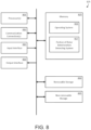
- FIG. 8 illustrates some exemplary components of another embodiment of a rotor deterioration detecting system 125 in accordance with the disclosure.
- the rotor deterioration detecting system 125 can include one or more input interfaces and output interfaces.
- Input interface 815 can be configured to receive various kinds of inputs such as resistance measurement data, start-up data, slow-roll time data, rotational speed, and a signature reference threshold.
- Output interface 820 can be configured for example, to output information to the graphical user interface 335 (shown in FIG. 3 ).
- the memory 825 can be used to store program instructions that are loadable and executable by the processor 805, as well as to store data generated during the execution of these programs.
- the memory 825 can be volatile (such as random access memory (RAM)) and/or non-volatile (such as read-only memory (ROM), flash memory, etc.).
- the memory devices can also include additional removable storage 830 and/or non-removable storage 835 including, but not limited to, magnetic storage, optical disks, and/or tape storage.
- the disk drives and their associated computer-readable media can provide non-volatile storage of computer-readable instructions, data structures, program modules, and other data.
- the memory 825 can include multiple different types of memory, such as static random access memory (SRAM), dynamic random access memory (DRAM), or ROM.
- SRAM static random access memory
- DRAM dynamic random access memory
- ROM read-only memory
- the memory 825, the removable storage, and the non-removable storage are all examples of non-transient computer-readable storage media.
- Such non-transient computer-readable storage media can be implemented in any method or technology for storage of information such as computer-readable instructions, data structures, program modules or other data. Additional types of non-transient computer storage media that can be present include, but are not limited to, programmable random access memory (PRAM), SRAM, DRAM, ROM, electrically erasable programmable read-only memory (EEPROM), compact disc read-only memory (CD-ROM), digital versatile discs (DVD) or other optical storage, magnetic cassettes, magnetic tapes, magnetic disk storage or other magnetic storage devices, or any other medium which can be used to store the desired information and which can be accessed by the processor 805. Combinations of any of the above should also be included within the scope of non-transient computer-readable media.
Landscapes
- Physics & Mathematics (AREA)
- General Physics & Mathematics (AREA)
- Chemical & Material Sciences (AREA)
- Engineering & Computer Science (AREA)
- Electrochemistry (AREA)
- Pathology (AREA)
- Life Sciences & Earth Sciences (AREA)
- Analytical Chemistry (AREA)
- Biochemistry (AREA)
- General Health & Medical Sciences (AREA)
- Immunology (AREA)
- Health & Medical Sciences (AREA)
- Chemical Kinetics & Catalysis (AREA)
- Microelectronics & Electronic Packaging (AREA)
- Power Engineering (AREA)
- Combustion & Propulsion (AREA)
- Tests Of Circuit Breakers, Generators, And Electric Motors (AREA)
- Control Of Eletrric Generators (AREA)
Claims (10)
- Système (100) comprenant :
une machine électrodynamique (110) comprenant :un enroulement inducteur (225) ; etun ensemble d'excitation (230) comprenant une bague collectrice (205), l'ensemble d'excitation (230) configuré pour alimenter l'enroulement inducteur (225) en courant continu (CC) par l'intermédiaire de la bague collectrice (205) ; et un système de détection de détérioration de rotor (125) comprenant :une unité de mesure de résistance (305) pour générer une diagraphie de valeurs de résistance (306) qui inclut des valeurs de résistance mesurées entre la bague collectrice (205) et l'enroulement inducteur (225) à différents intervalles lorsque la machine électrodynamique (110) est en fonctionnement ;un convertisseur du domaine temporel vers le domaine fréquentiel (310) qui utilise au moins une partie de la diagraphie de valeurs de résistance (306) pour générer une signature spectrale (600) d'une mesure de résistance de rotor qui est réalisée lorsque la machine électrodynamique (110) est soumise à un mode de fonctionnement en rotation lente ;un système d'analyse spectrale (315) qui détermine un niveau de modification dans la résistance de rotor sur la base, au moins en partie, de l'évaluation d'une ou de plusieurs composante(s) harmonique(s) (610) lorsqu'elles sont présentes dans la signature spectrale (600) générée par le convertisseur du domaine temporel vers le domaine fréquentiel (310) ; un calculateur de détérioration de rotor (330) qui délivre au moins l'un parmi un état modifié de résistance de rotor de la machine électrodynamique (110) pendant le mode de fonctionnement en rotation lente, ou une tendance de modification de résistance de rotor de la machine électrodynamique (110), sur la base au moins en partie du traitement du niveau de modification dans la résistance de rotor déterminée par le système d'analyse spectrale (315) ; etune interface utilisateur graphique (335) pour afficher au moins l'un parmi l'état modifié de résistance de rotor ou la tendance de modification de résistance de rotor, et pour accepter une entrée d'utilisateur associée au système de détection de détérioration de rotor (125), dans lequel la partie de la diagraphie de valeurs de résistance (306) utilisée par le convertisseur du domaine temporel vers le domaine fréquentiel (310) pour générer la signature spectrale (600) comprend une pluralité de valeurs de résistance mesurées à chacune d'une pluralité de positions angulaires d'un ensemble rotor (115) de la machine électrodynamique (110) et dans lequel chacune de la pluralité de valeurs de résistance est issue de mesures de tension continue et de mesures de courant continu réalisées, par l'intermédiaire de l'ensemble d'excitation, à chacune d'un ensemble de vitesses de rotation prédéfinies de l'ensemble rotor. - Système (100) selon la revendication 1, dans lequel le système de détection de détérioration de rotor (125) comprend en outre :un compteur d'événement de démarrage (320) qui fournit un comptage cumulé d'opérations de démarrage effectuées sur la machine électrodynamique (110) ; etun temporisateur (325) qui fournit une mesure du temps de fonctionnement cumulée qui est indicative d'une durée totale de temps pendant laquelle la machine électrodynamique (110) a été soumise au mode de fonctionnement en rotation lente.
- Système (100) selon la revendication 2, dans lequel le calculateur de détérioration de rotor (330) détermine la tendance de modification de résistance sur la base du traitement d'une combinaison d'au moins une partie du comptage cumulé d'opérations de démarrage, d'au moins une partie de la mesure du temps de fonctionnement cumulée et du niveau de modification dans la résistance de rotor déterminée par le système d'analyse spectrale (315).
- Système (100) selon la revendication 1, dans lequel le système d'analyse spectrale (315) détermine le niveau de modification dans la résistance de rotor, au moins en partie, en utilisant un seuil de référence de signature qui est issu d'un premier ensemble de mesures de résistance réalisées lorsque la machine électrodynamique (110) est mise en service pour la première fois.
- Système (100) selon la revendication 5, dans lequel le système d'analyse spectrale (315) indique le niveau de modification dans la résistance de rotor en tant que pourcentage de détérioration par rapport au seuil de référence de signature.
- Procédé comprenant :la fourniture d'une machine électrodynamique (110) comprenant un enroulement inducteur (225) et un ensemble d'excitation (230), l'ensemble d'excitation (230) comprenant une bague collectrice (205) pour alimenter en courant continu (CC) l'enroulement inducteur (225) ;la génération d'une diagraphie de valeurs de résistance (306) qui inclut des valeurs de résistance mesurées entre la bague collectrice (205) et l'enroulement inducteur (225) à différents intervalles lorsque la machine électrodynamique (110) est en fonctionnement ;l'utilisation d'au moins une partie de la diagraphie de valeurs de résistance (306) par un convertisseur de domaine temporel vers le domaine fréquentiel (310) pour générer une signature spectrale (600) d'une mesure de résistance de rotor qui est réalisée lorsque la machine électrodynamique (110) est soumise à un mode de fonctionnement en rotation lente ;la détermination d'un niveau de modification dans la résistance de rotor sur la base au moins en partie de l'évaluation d'une ou de plusieurs composantes harmoniques (610) lorsqu'elles sont présentes dans la signature spectrale (600) ;la détermination d'au moins l'un parmi un état modifié de résistance de rotor de la machine électrodynamique (110) pendant le mode de fonctionnement en rotation lente, ou une tendance de modification de résistance de rotor de la machine électrodynamique (110), sur la base au moins en partie de traitement du niveau de modification dans la résistance de rotor ; etla réalisation d'au moins l'une parmi une procédure de réparation ou une procédure d'entretien sur un ou plusieurs composants de la machine électrodynamique (110) sur la base de l'au moins un parmi l'état modifié de résistance de rotor ou la tendance de modification de résistance de rotor, dans lequel la partie de la diagraphie de valeurs de résistance (306) utilisée par le convertisseur du domaine temporel vers le domaine fréquentiel (310) pour générer la signature spectrale (600) comprend une pluralité de valeurs de résistance mesurées à chacune d'une pluralité de positions angulaires d'un ensemble rotor (115) de la machine électrodynamique (110) et dans lequel chacune parmi la pluralité de valeurs de résistance est issue de mesures de tension continue et de mesures de courant continu réalisées, par l'intermédiare de l'ensemble d'excitation, à chacune d'un ensemble de vitesses de rotation prédéfinies de l'ensemble rotor.
- Procédé selon la revendication 6, comprenant en outre :la génération d'un comptage cumulé d'opérations de démarrage effectuées sur la machine électrodynamique (110) ;l'obtention d'une mesure de temps de fonctionnement cumulé qui est indicative d'une durée totale pendant laquelle la machine électrodynamique (110) a été soumise au mode de fonctionnement en rotation lente ; etla détermination de la tendance de modification de résistance sur la base du traitement d'une combinaison d'au moins une partie du comptage cumulé d'opérations de démarrage, au moins une partie de la mesure du temps de fonctionnement cumulée et le niveau de modification dans la résistance de rotor.
- Procédé selon la revendication 6, dans lequel la diagraphie de valeurs de résistance (306) comprend une pluralité de valeurs de résistance mesurées à chacune d'une pluralité de positions angulaires d'un ensemble rotor (115) de la machine électrodynamique (110) en rotation lente.
- Procédé selon la revendication 6, dans lequel la détermination du niveau de modification dans la résistance de rotor est en outre basée sur l'utilisation d'un seuil de référence de signature qui est issu d'un premier ensemble de mesures de résistance réalisées lorsque la machine électrodynamique (110) est mise en service pour la première fois.
- Procédé selon la revendication 9, dans lequel le premier ensemble de valeurs de résistance est caractérisé au moins en partie, par une absence de composantes harmoniques (610) dans une représentation spectrale.
Applications Claiming Priority (1)
| Application Number | Priority Date | Filing Date | Title |
|---|---|---|---|
| IN201641021321 | 2016-06-21 |
Publications (2)
| Publication Number | Publication Date |
|---|---|
| EP3260874A1 EP3260874A1 (fr) | 2017-12-27 |
| EP3260874B1 true EP3260874B1 (fr) | 2023-12-20 |
Family
ID=59101314
Family Applications (1)
| Application Number | Title | Priority Date | Filing Date |
|---|---|---|---|
| EP17176928.4A Active EP3260874B1 (fr) | 2016-06-21 | 2017-06-20 | Systèmes et procédés pour déterminer la détérioration de rotor d'une machine dynamoélectrique |
Country Status (3)
| Country | Link |
|---|---|
| US (1) | US10914701B2 (fr) |
| EP (1) | EP3260874B1 (fr) |
| ES (1) | ES2970562T3 (fr) |
Families Citing this family (4)
| Publication number | Priority date | Publication date | Assignee | Title |
|---|---|---|---|---|
| JP7330006B2 (ja) * | 2019-07-29 | 2023-08-21 | 株式会社東芝 | 界磁巻線層間短絡検知装置および界磁巻線層間短絡検知方法 |
| US20210278476A1 (en) * | 2020-03-09 | 2021-09-09 | Mitsubishi Electric Research Laboratories, Inc. | System and Method of Fault Detection Based on Robust Damped Signal Demixing |
| CN115575710A (zh) * | 2022-10-18 | 2023-01-06 | 国网青海省电力公司电力科学研究院 | 调相机转子阻值测试方法以及装置 |
| CN118826557A (zh) * | 2023-04-18 | 2024-10-22 | 蔚来动力科技(合肥)有限公司 | 用于确定感应电机转子电阻的方法和装置 |
Family Cites Families (28)
| Publication number | Priority date | Publication date | Assignee | Title |
|---|---|---|---|---|
| GB2157835B (en) | 1984-04-11 | 1987-10-21 | Central Electr Generat Board | Monitoring earth faults on dynamoelectrics machines |
| US4761703A (en) | 1987-08-31 | 1988-08-02 | Electric Power Research Institute, Inc. | Rotor fault detector for induction motors |
| CA2106357A1 (fr) | 1993-07-07 | 1995-01-08 | Murty V. V. S. Yalla | Methode de realisation de fonctions de relais de protection selectionnables |
| US6035265A (en) | 1997-10-08 | 2000-03-07 | Reliance Electric Industrial Company | System to provide low cost excitation to stator winding to generate impedance spectrum for use in stator diagnostics |
| US6323658B1 (en) * | 1997-10-08 | 2001-11-27 | Reliance Electric Technologies, Llc | Method of conducting broadband impedance response tests to predict stator winding failure |
| US6199018B1 (en) * | 1998-03-04 | 2001-03-06 | Emerson Electric Co. | Distributed diagnostic system |
| US7034706B1 (en) | 1999-05-06 | 2006-04-25 | Nippes Paul I | Early warning and problem detection in rotating machinery by monitoring shaft voltage and/or grounding current |
| US6280265B1 (en) | 1999-08-04 | 2001-08-28 | General Electric Co. | Electrical connection between and a method of installation of a main terminal and a bore copper of a dynamoelectric machine |
| CN1494658A (zh) | 2000-11-08 | 2004-05-05 | 通用电气公司 | 检测和计算接地故障电阻的设备和方法 |
| US7834573B2 (en) | 2007-07-31 | 2010-11-16 | Caterpillar Inc | Winding fault detection system |
| US20090219030A1 (en) | 2008-02-29 | 2009-09-03 | General Electric Company | Methods and Systems for Detecting Rotor Field Ground Faults In Rotating Machinery |
| NO2370801T3 (fr) | 2008-12-22 | 2018-04-21 | ||
| US9304033B2 (en) | 2008-12-22 | 2016-04-05 | S.P.M. Instrument Ab | Analysis system |
| US8810396B2 (en) | 2008-12-22 | 2014-08-19 | S.P.M. Instrument Ab | Analysis system |
| EP4024013B1 (fr) | 2008-12-22 | 2025-02-19 | S.P.M. Instrument AB | Système d'analyse |
| US8384338B2 (en) | 2009-01-30 | 2013-02-26 | Eaton Corporation | System and method for determining stator winding resistance in an AC motor using motor drives |
| CN102449445B (zh) | 2009-05-05 | 2014-12-17 | S.P.M.仪器公司 | 用于分析具有旋转部件的机器振动的设备和方法 |
| US8405339B2 (en) | 2010-07-01 | 2013-03-26 | Eaton Corporation | System and method for detecting fault in an AC machine |
| DE102012106543A1 (de) | 2011-07-28 | 2013-01-31 | General Electric Company | Verfahren und System zur Überwachung einer Synchronmaschine |
| GB2493280B (en) | 2011-07-28 | 2016-02-17 | Gen Electric | Method and system for monitoring a synchronous machine |
| ITFI20110269A1 (it) * | 2011-12-12 | 2013-06-13 | Nuovo Pignone Spa | "turning gear for gas turbine arrangements" |
| US10359473B2 (en) * | 2012-05-29 | 2019-07-23 | Nutech Ventures | Detecting faults in turbine generators |
| DK2725370T3 (en) | 2012-10-26 | 2015-03-30 | Abb Technology Ag | Method for diagnosis of electro-mechanical system based on impedance analysis |
| WO2014117279A1 (fr) | 2013-02-04 | 2014-08-07 | University Of Saskatchewan | Procédés et appareil pour une détection de défaillances de générateur |
| CN103267587A (zh) | 2013-03-18 | 2013-08-28 | 国电南瑞科技股份有限公司 | 一种大型水轮发电机组转子绕组温度的测算方法 |
| GB201404226D0 (en) | 2014-03-11 | 2014-04-23 | Rolls Royce Plc | Fault detection in induction machines |
| GB201503930D0 (en) * | 2015-03-09 | 2015-04-22 | Rolls Royce Plc | Fault detection and diagnosis in an induction motor |
| CN205246758U (zh) | 2015-11-27 | 2016-05-18 | 湖北华电电力工程有限公司 | 一种用于测量电机转子绕组电阻的测试装置 |
-
2017
- 2017-06-19 US US15/626,708 patent/US10914701B2/en active Active
- 2017-06-20 EP EP17176928.4A patent/EP3260874B1/fr active Active
- 2017-06-20 ES ES17176928T patent/ES2970562T3/es active Active
Also Published As
| Publication number | Publication date |
|---|---|
| US10914701B2 (en) | 2021-02-09 |
| ES2970562T3 (es) | 2024-05-29 |
| EP3260874A1 (fr) | 2017-12-27 |
| US20170363559A1 (en) | 2017-12-21 |
Similar Documents
| Publication | Publication Date | Title |
|---|---|---|
| JP5875734B2 (ja) | 電動機の診断装置および開閉装置 | |
| US10495693B2 (en) | Wind turbine fault detection using acoustic, vibration, and electrical signals | |
| Artigao et al. | In-service wind turbine DFIG diagnosis using current signature analysis | |
| US8994359B2 (en) | Fault detection based on current signature analysis for a generator | |
| US9645046B2 (en) | Fault detection system and associated method | |
| US10914701B2 (en) | Systems and methods for determining rotor deterioration in a dynamoelectric machine | |
| JP5733913B2 (ja) | 回転機械系の異常診断方法 | |
| CN102840911B (zh) | 用于旋转机械的振动烈度分析装置和方法 | |
| Fournier et al. | Current-based detection of mechanical unbalance in an induction machine using spectral kurtosis with reference | |
| EP3480610B1 (fr) | Diagnostic d'un ensemble d'enroulement d'un stator | |
| JP7109656B2 (ja) | 電動機設備の異常診断装置、電動機設備の異常診断方法、および電動機設備の異常診断システム | |
| CN103792463B (zh) | 基于虚功率原理的汽轮发电机转子绕组短路故障诊断方法 | |
| GB2534406A (en) | Fault detection and diagnosis | |
| CN103926506A (zh) | 基于构建函数的汽轮发电机转子绕组短路故障诊断方法 | |
| Messaoudi et al. | Multiple Faults Diagnosis in Induction Motor Using the MCSA Method. | |
| EP3419162A1 (fr) | Analyse de signatures électriques de machines tournantes électriques | |
| JP2015004694A (ja) | 回転機械系の異常診断方法 | |
| Mustafa et al. | Principal component analysis anomaly detector for rotor broken bars | |
| Bradiya et al. | Utilization of Signal Analysis Techniques in Investigation of Rotor Broken Bars and Misalignment Defects on low power Induction Machines | |
| Bind et al. | Fault Analysis of An Induction Motors Using AI and ML: An Efficient Way | |
| Skrimpas et al. | Automatic mechanical fault assessment of small wind energy systems in microgrids using electric signature analysis | |
| EP4535018A1 (fr) | Procédé et système de détection d'excentricité d'entrefer dans des machines rotatives | |
| CN114658611B (zh) | 风力发电机的主轴承异常检测方法和主轴承异常检测装置 | |
| EP4308797B1 (fr) | Procédé de détection automatique de frottement synchrone dans une turbine | |
| Jeevanand et al. | State of art on condition monitoring of induction motors |
Legal Events
| Date | Code | Title | Description |
|---|---|---|---|
| PUAI | Public reference made under article 153(3) epc to a published international application that has entered the european phase |
Free format text: ORIGINAL CODE: 0009012 |
|
| STAA | Information on the status of an ep patent application or granted ep patent |
Free format text: STATUS: THE APPLICATION HAS BEEN PUBLISHED |
|
| AK | Designated contracting states |
Kind code of ref document: A1 Designated state(s): AL AT BE BG CH CY CZ DE DK EE ES FI FR GB GR HR HU IE IS IT LI LT LU LV MC MK MT NL NO PL PT RO RS SE SI SK SM TR |
|
| AX | Request for extension of the european patent |
Extension state: BA ME |
|
| STAA | Information on the status of an ep patent application or granted ep patent |
Free format text: STATUS: REQUEST FOR EXAMINATION WAS MADE |
|
| 17P | Request for examination filed |
Effective date: 20180627 |
|
| RBV | Designated contracting states (corrected) |
Designated state(s): AL AT BE BG CH CY CZ DE DK EE ES FI FR GB GR HR HU IE IS IT LI LT LU LV MC MK MT NL NO PL PT RO RS SE SI SK SM TR |
|
| STAA | Information on the status of an ep patent application or granted ep patent |
Free format text: STATUS: EXAMINATION IS IN PROGRESS |
|
| 17Q | First examination report despatched |
Effective date: 20210527 |
|
| GRAP | Despatch of communication of intention to grant a patent |
Free format text: ORIGINAL CODE: EPIDOSNIGR1 |
|
| STAA | Information on the status of an ep patent application or granted ep patent |
Free format text: STATUS: GRANT OF PATENT IS INTENDED |
|
| INTG | Intention to grant announced |
Effective date: 20230710 |
|
| GRAS | Grant fee paid |
Free format text: ORIGINAL CODE: EPIDOSNIGR3 |
|
| GRAA | (expected) grant |
Free format text: ORIGINAL CODE: 0009210 |
|
| STAA | Information on the status of an ep patent application or granted ep patent |
Free format text: STATUS: THE PATENT HAS BEEN GRANTED |
|
| RAP1 | Party data changed (applicant data changed or rights of an application transferred) |
Owner name: GENERAL ELECTRIC TECHNOLOGY GMBH |
|
| AK | Designated contracting states |
Kind code of ref document: B1 Designated state(s): AL AT BE BG CH CY CZ DE DK EE ES FI FR GB GR HR HU IE IS IT LI LT LU LV MC MK MT NL NO PL PT RO RS SE SI SK SM TR |
|
| REG | Reference to a national code |
Ref country code: GB Ref legal event code: FG4D |
|
| REG | Reference to a national code |
Ref country code: DE Ref legal event code: R096 Ref document number: 602017077642 Country of ref document: DE |
|
| REG | Reference to a national code |
Ref country code: CH Ref legal event code: EP |
|
| REG | Reference to a national code |
Ref country code: IE Ref legal event code: FG4D |
|
| PG25 | Lapsed in a contracting state [announced via postgrant information from national office to epo] |
Ref country code: GR Free format text: LAPSE BECAUSE OF FAILURE TO SUBMIT A TRANSLATION OF THE DESCRIPTION OR TO PAY THE FEE WITHIN THE PRESCRIBED TIME-LIMIT Effective date: 20240321 |
|
| REG | Reference to a national code |
Ref country code: LT Ref legal event code: MG9D |
|
| PG25 | Lapsed in a contracting state [announced via postgrant information from national office to epo] |
Ref country code: LT Free format text: LAPSE BECAUSE OF FAILURE TO SUBMIT A TRANSLATION OF THE DESCRIPTION OR TO PAY THE FEE WITHIN THE PRESCRIBED TIME-LIMIT Effective date: 20231220 |
|
| REG | Reference to a national code |
Ref country code: NL Ref legal event code: MP Effective date: 20231220 |
|
| PG25 | Lapsed in a contracting state [announced via postgrant information from national office to epo] |
Ref country code: LT Free format text: LAPSE BECAUSE OF FAILURE TO SUBMIT A TRANSLATION OF THE DESCRIPTION OR TO PAY THE FEE WITHIN THE PRESCRIBED TIME-LIMIT Effective date: 20231220 Ref country code: GR Free format text: LAPSE BECAUSE OF FAILURE TO SUBMIT A TRANSLATION OF THE DESCRIPTION OR TO PAY THE FEE WITHIN THE PRESCRIBED TIME-LIMIT Effective date: 20240321 Ref country code: FI Free format text: LAPSE BECAUSE OF FAILURE TO SUBMIT A TRANSLATION OF THE DESCRIPTION OR TO PAY THE FEE WITHIN THE PRESCRIBED TIME-LIMIT Effective date: 20231220 Ref country code: BG Free format text: LAPSE BECAUSE OF FAILURE TO SUBMIT A TRANSLATION OF THE DESCRIPTION OR TO PAY THE FEE WITHIN THE PRESCRIBED TIME-LIMIT Effective date: 20240320 |
|
| REG | Reference to a national code |
Ref country code: AT Ref legal event code: MK05 Ref document number: 1642902 Country of ref document: AT Kind code of ref document: T Effective date: 20231220 |
|
| PG25 | Lapsed in a contracting state [announced via postgrant information from national office to epo] |
Ref country code: NL Free format text: LAPSE BECAUSE OF FAILURE TO SUBMIT A TRANSLATION OF THE DESCRIPTION OR TO PAY THE FEE WITHIN THE PRESCRIBED TIME-LIMIT Effective date: 20231220 |
|
| REG | Reference to a national code |
Ref country code: ES Ref legal event code: FG2A Ref document number: 2970562 Country of ref document: ES Kind code of ref document: T3 Effective date: 20240529 |
|
| PG25 | Lapsed in a contracting state [announced via postgrant information from national office to epo] |
Ref country code: SE Free format text: LAPSE BECAUSE OF FAILURE TO SUBMIT A TRANSLATION OF THE DESCRIPTION OR TO PAY THE FEE WITHIN THE PRESCRIBED TIME-LIMIT Effective date: 20231220 Ref country code: RS Free format text: LAPSE BECAUSE OF FAILURE TO SUBMIT A TRANSLATION OF THE DESCRIPTION OR TO PAY THE FEE WITHIN THE PRESCRIBED TIME-LIMIT Effective date: 20231220 Ref country code: NO Free format text: LAPSE BECAUSE OF FAILURE TO SUBMIT A TRANSLATION OF THE DESCRIPTION OR TO PAY THE FEE WITHIN THE PRESCRIBED TIME-LIMIT Effective date: 20240320 Ref country code: NL Free format text: LAPSE BECAUSE OF FAILURE TO SUBMIT A TRANSLATION OF THE DESCRIPTION OR TO PAY THE FEE WITHIN THE PRESCRIBED TIME-LIMIT Effective date: 20231220 Ref country code: LV Free format text: LAPSE BECAUSE OF FAILURE TO SUBMIT A TRANSLATION OF THE DESCRIPTION OR TO PAY THE FEE WITHIN THE PRESCRIBED TIME-LIMIT Effective date: 20231220 Ref country code: HR Free format text: LAPSE BECAUSE OF FAILURE TO SUBMIT A TRANSLATION OF THE DESCRIPTION OR TO PAY THE FEE WITHIN THE PRESCRIBED TIME-LIMIT Effective date: 20231220 |
|
| PG25 | Lapsed in a contracting state [announced via postgrant information from national office to epo] |
Ref country code: IS Free format text: LAPSE BECAUSE OF FAILURE TO SUBMIT A TRANSLATION OF THE DESCRIPTION OR TO PAY THE FEE WITHIN THE PRESCRIBED TIME-LIMIT Effective date: 20240420 |
|
| PG25 | Lapsed in a contracting state [announced via postgrant information from national office to epo] |
Ref country code: AT Free format text: LAPSE BECAUSE OF FAILURE TO SUBMIT A TRANSLATION OF THE DESCRIPTION OR TO PAY THE FEE WITHIN THE PRESCRIBED TIME-LIMIT Effective date: 20231220 Ref country code: CZ Free format text: LAPSE BECAUSE OF FAILURE TO SUBMIT A TRANSLATION OF THE DESCRIPTION OR TO PAY THE FEE WITHIN THE PRESCRIBED TIME-LIMIT Effective date: 20231220 |
|
| PG25 | Lapsed in a contracting state [announced via postgrant information from national office to epo] |
Ref country code: SK Free format text: LAPSE BECAUSE OF FAILURE TO SUBMIT A TRANSLATION OF THE DESCRIPTION OR TO PAY THE FEE WITHIN THE PRESCRIBED TIME-LIMIT Effective date: 20231220 |
|
| PG25 | Lapsed in a contracting state [announced via postgrant information from national office to epo] |
Ref country code: SM Free format text: LAPSE BECAUSE OF FAILURE TO SUBMIT A TRANSLATION OF THE DESCRIPTION OR TO PAY THE FEE WITHIN THE PRESCRIBED TIME-LIMIT Effective date: 20231220 Ref country code: SK Free format text: LAPSE BECAUSE OF FAILURE TO SUBMIT A TRANSLATION OF THE DESCRIPTION OR TO PAY THE FEE WITHIN THE PRESCRIBED TIME-LIMIT Effective date: 20231220 Ref country code: RO Free format text: LAPSE BECAUSE OF FAILURE TO SUBMIT A TRANSLATION OF THE DESCRIPTION OR TO PAY THE FEE WITHIN THE PRESCRIBED TIME-LIMIT Effective date: 20231220 Ref country code: IT Free format text: LAPSE BECAUSE OF FAILURE TO SUBMIT A TRANSLATION OF THE DESCRIPTION OR TO PAY THE FEE WITHIN THE PRESCRIBED TIME-LIMIT Effective date: 20231220 Ref country code: IS Free format text: LAPSE BECAUSE OF FAILURE TO SUBMIT A TRANSLATION OF THE DESCRIPTION OR TO PAY THE FEE WITHIN THE PRESCRIBED TIME-LIMIT Effective date: 20240420 Ref country code: EE Free format text: LAPSE BECAUSE OF FAILURE TO SUBMIT A TRANSLATION OF THE DESCRIPTION OR TO PAY THE FEE WITHIN THE PRESCRIBED TIME-LIMIT Effective date: 20231220 Ref country code: CZ Free format text: LAPSE BECAUSE OF FAILURE TO SUBMIT A TRANSLATION OF THE DESCRIPTION OR TO PAY THE FEE WITHIN THE PRESCRIBED TIME-LIMIT Effective date: 20231220 Ref country code: AT Free format text: LAPSE BECAUSE OF FAILURE TO SUBMIT A TRANSLATION OF THE DESCRIPTION OR TO PAY THE FEE WITHIN THE PRESCRIBED TIME-LIMIT Effective date: 20231220 |
|
| PG25 | Lapsed in a contracting state [announced via postgrant information from national office to epo] |
Ref country code: PT Free format text: LAPSE BECAUSE OF FAILURE TO SUBMIT A TRANSLATION OF THE DESCRIPTION OR TO PAY THE FEE WITHIN THE PRESCRIBED TIME-LIMIT Effective date: 20240422 Ref country code: PL Free format text: LAPSE BECAUSE OF FAILURE TO SUBMIT A TRANSLATION OF THE DESCRIPTION OR TO PAY THE FEE WITHIN THE PRESCRIBED TIME-LIMIT Effective date: 20231220 |
|
| PG25 | Lapsed in a contracting state [announced via postgrant information from national office to epo] |
Ref country code: PT Free format text: LAPSE BECAUSE OF FAILURE TO SUBMIT A TRANSLATION OF THE DESCRIPTION OR TO PAY THE FEE WITHIN THE PRESCRIBED TIME-LIMIT Effective date: 20240422 Ref country code: PL Free format text: LAPSE BECAUSE OF FAILURE TO SUBMIT A TRANSLATION OF THE DESCRIPTION OR TO PAY THE FEE WITHIN THE PRESCRIBED TIME-LIMIT Effective date: 20231220 |
|
| REG | Reference to a national code |
Ref country code: DE Ref legal event code: R097 Ref document number: 602017077642 Country of ref document: DE |
|
| PG25 | Lapsed in a contracting state [announced via postgrant information from national office to epo] |
Ref country code: DK Free format text: LAPSE BECAUSE OF FAILURE TO SUBMIT A TRANSLATION OF THE DESCRIPTION OR TO PAY THE FEE WITHIN THE PRESCRIBED TIME-LIMIT Effective date: 20231220 |
|
| PGFP | Annual fee paid to national office [announced via postgrant information from national office to epo] |
Ref country code: ES Payment date: 20240701 Year of fee payment: 8 |
|
| PLBE | No opposition filed within time limit |
Free format text: ORIGINAL CODE: 0009261 |
|
| STAA | Information on the status of an ep patent application or granted ep patent |
Free format text: STATUS: NO OPPOSITION FILED WITHIN TIME LIMIT |
|
| PG25 | Lapsed in a contracting state [announced via postgrant information from national office to epo] |
Ref country code: SI Free format text: LAPSE BECAUSE OF FAILURE TO SUBMIT A TRANSLATION OF THE DESCRIPTION OR TO PAY THE FEE WITHIN THE PRESCRIBED TIME-LIMIT Effective date: 20231220 |
|
| PG25 | Lapsed in a contracting state [announced via postgrant information from national office to epo] |
Ref country code: SI Free format text: LAPSE BECAUSE OF FAILURE TO SUBMIT A TRANSLATION OF THE DESCRIPTION OR TO PAY THE FEE WITHIN THE PRESCRIBED TIME-LIMIT Effective date: 20231220 Ref country code: DK Free format text: LAPSE BECAUSE OF FAILURE TO SUBMIT A TRANSLATION OF THE DESCRIPTION OR TO PAY THE FEE WITHIN THE PRESCRIBED TIME-LIMIT Effective date: 20231220 |
|
| 26N | No opposition filed |
Effective date: 20240923 |
|
| PG25 | Lapsed in a contracting state [announced via postgrant information from national office to epo] |
Ref country code: MC Free format text: LAPSE BECAUSE OF FAILURE TO SUBMIT A TRANSLATION OF THE DESCRIPTION OR TO PAY THE FEE WITHIN THE PRESCRIBED TIME-LIMIT Effective date: 20231220 |
|
| PG25 | Lapsed in a contracting state [announced via postgrant information from national office to epo] |
Ref country code: LU Free format text: LAPSE BECAUSE OF NON-PAYMENT OF DUE FEES Effective date: 20240620 |
|
| GBPC | Gb: european patent ceased through non-payment of renewal fee |
Effective date: 20240620 |
|
| PG25 | Lapsed in a contracting state [announced via postgrant information from national office to epo] |
Ref country code: IE Free format text: LAPSE BECAUSE OF NON-PAYMENT OF DUE FEES Effective date: 20240620 |
|
| PG25 | Lapsed in a contracting state [announced via postgrant information from national office to epo] |
Ref country code: BE Free format text: LAPSE BECAUSE OF NON-PAYMENT OF DUE FEES Effective date: 20240630 |
|
| PG25 | Lapsed in a contracting state [announced via postgrant information from national office to epo] |
Ref country code: GB Free format text: LAPSE BECAUSE OF NON-PAYMENT OF DUE FEES Effective date: 20240620 |
|
| REG | Reference to a national code |
Ref country code: BE Ref legal event code: MM Effective date: 20240630 |
|
| PGFP | Annual fee paid to national office [announced via postgrant information from national office to epo] |
Ref country code: DE Payment date: 20250520 Year of fee payment: 9 |
|
| PGFP | Annual fee paid to national office [announced via postgrant information from national office to epo] |
Ref country code: FR Payment date: 20250520 Year of fee payment: 9 |
|
| PGFP | Annual fee paid to national office [announced via postgrant information from national office to epo] |
Ref country code: CH Payment date: 20250701 Year of fee payment: 9 |
|
| PG25 | Lapsed in a contracting state [announced via postgrant information from national office to epo] |
Ref country code: CY Free format text: LAPSE BECAUSE OF FAILURE TO SUBMIT A TRANSLATION OF THE DESCRIPTION OR TO PAY THE FEE WITHIN THE PRESCRIBED TIME-LIMIT; INVALID AB INITIO Effective date: 20170620 |
|
| PG25 | Lapsed in a contracting state [announced via postgrant information from national office to epo] |
Ref country code: HU Free format text: LAPSE BECAUSE OF FAILURE TO SUBMIT A TRANSLATION OF THE DESCRIPTION OR TO PAY THE FEE WITHIN THE PRESCRIBED TIME-LIMIT; INVALID AB INITIO Effective date: 20170620 |