EP4535018A1 - Procédé et système de détection d'excentricité d'entrefer dans des machines rotatives - Google Patents
Procédé et système de détection d'excentricité d'entrefer dans des machines rotatives Download PDFInfo
- Publication number
- EP4535018A1 EP4535018A1 EP24202748.0A EP24202748A EP4535018A1 EP 4535018 A1 EP4535018 A1 EP 4535018A1 EP 24202748 A EP24202748 A EP 24202748A EP 4535018 A1 EP4535018 A1 EP 4535018A1
- Authority
- EP
- European Patent Office
- Prior art keywords
- eccentricity
- flux density
- rotating machine
- air gap
- density distribution
- Prior art date
- Legal status (The legal status is an assumption and is not a legal conclusion. Google has not performed a legal analysis and makes no representation as to the accuracy of the status listed.)
- Pending
Links
- 238000000034 method Methods 0.000 title claims abstract description 70
- 238000001514 detection method Methods 0.000 title abstract description 7
- 230000004907 flux Effects 0.000 claims abstract description 282
- 238000005259 measurement Methods 0.000 claims abstract description 153
- 238000009826 distribution Methods 0.000 claims description 131
- 230000003068 static effect Effects 0.000 claims description 71
- 230000015654 memory Effects 0.000 claims description 20
- 238000012545 processing Methods 0.000 description 18
- 238000004891 communication Methods 0.000 description 10
- 238000003860 storage Methods 0.000 description 9
- 238000010586 diagram Methods 0.000 description 8
- 230000008859 change Effects 0.000 description 7
- 238000012423 maintenance Methods 0.000 description 5
- 230000008569 process Effects 0.000 description 5
- 230000003750 conditioning effect Effects 0.000 description 4
- 230000007423 decrease Effects 0.000 description 4
- 230000006698 induction Effects 0.000 description 4
- 238000004519 manufacturing process Methods 0.000 description 4
- 230000009471 action Effects 0.000 description 3
- 238000006243 chemical reaction Methods 0.000 description 3
- 238000009434 installation Methods 0.000 description 3
- 238000009413 insulation Methods 0.000 description 3
- 238000012544 monitoring process Methods 0.000 description 3
- 238000007781 pre-processing Methods 0.000 description 3
- 229920001621 AMOLED Polymers 0.000 description 2
- 238000004458 analytical method Methods 0.000 description 2
- 230000015556 catabolic process Effects 0.000 description 2
- 238000010276 construction Methods 0.000 description 2
- 238000006731 degradation reaction Methods 0.000 description 2
- 230000000694 effects Effects 0.000 description 2
- 230000007246 mechanism Effects 0.000 description 2
- 238000012986 modification Methods 0.000 description 2
- 230000004048 modification Effects 0.000 description 2
- 230000003321 amplification Effects 0.000 description 1
- 238000004590 computer program Methods 0.000 description 1
- 230000001143 conditioned effect Effects 0.000 description 1
- 230000007797 corrosion Effects 0.000 description 1
- 238000005260 corrosion Methods 0.000 description 1
- 238000005516 engineering process Methods 0.000 description 1
- 238000001914 filtration Methods 0.000 description 1
- 238000010438 heat treatment Methods 0.000 description 1
- 238000002955 isolation Methods 0.000 description 1
- 239000004973 liquid crystal related substance Substances 0.000 description 1
- 239000003607 modifier Substances 0.000 description 1
- 238000003199 nucleic acid amplification method Methods 0.000 description 1
- 230000003287 optical effect Effects 0.000 description 1
- 230000002093 peripheral effect Effects 0.000 description 1
- 230000008439 repair process Effects 0.000 description 1
- 239000004065 semiconductor Substances 0.000 description 1
- 238000001228 spectrum Methods 0.000 description 1
- 238000010183 spectrum analysis Methods 0.000 description 1
- 239000010409 thin film Substances 0.000 description 1
- 230000007704 transition Effects 0.000 description 1
- 230000000007 visual effect Effects 0.000 description 1
- 238000012800 visualization Methods 0.000 description 1
- 238000004804 winding Methods 0.000 description 1
Images




Classifications
-
- G—PHYSICS
- G01—MEASURING; TESTING
- G01R—MEASURING ELECTRIC VARIABLES; MEASURING MAGNETIC VARIABLES
- G01R31/00—Arrangements for testing electric properties; Arrangements for locating electric faults; Arrangements for electrical testing characterised by what is being tested not provided for elsewhere
- G01R31/34—Testing dynamo-electric machines
- G01R31/343—Testing dynamo-electric machines in operation
Definitions
- the one or more magnetic sensors 110 may be adapted to be mounted at any location of the rotating machine 110 or proximate to the rotating machine 100 and at any direction subject to receiving the external leakage flux measurements generated by the rotating machine 100 for processing and determining the air gap eccentricity condition of the rotating machine 100.
- magnetic sensors 110a, 110b and 110d are mounted on outer surface i.e., frame, of the rotating machine and the magnetic sensor 110c is mounted on end cover of the rotating machine 100. It shall be noted that when a plurality of magnetic sensors, for example, the magnetic sensors 110a, 110b, 110c and 110d are used, the external leakage flux measurements from the magnetic sensors 110a, 110b, 110c, 110d may be analyzed separately to determine the air gap eccentricity in the rotating machine 100.
- the communication interface 208 may include mechanisms configured to communicate with external entities/peripheral devices, for example, the one or more magnetic sensors 110a, 110b, 110c, 110d associated with the rotating machine 100, remote servers, etc.
- the communication interface 208 is configured to receive the external leakage flux measurements from each magnetic sensor of the one or more magnetic sensors 110 for processing by the processor 202.
- the external leakage flux measurements are made by the one or more magnetic sensors 110 mounted on the rotating machine 100 or placed proximal to the body 108 of the rotating machine 100 so as to measure the external leakage flux of the rotating machine 100.
- the external leakage flux measurements are forwarded to the processor 202 which performs one or more operations described herein to detect air gap eccentricity in the rotating machine 100.
- the external leakage flux measurements received from the one or more magnetic sensors 110 may be conditioned prior to processing by the processor 202.
- the system 150 may include other components for pre-processing the external leakage flux measurements received from the one or more magnetic sensors 110, for example, a signal conditioner (not shown in FIG. 2 ).
- signal conditioning is a process of manipulating an analog signal (here the ⁇ magnetic flux measurement') in such way that it is optimized for further processing.
- signal conditioning of the magnetic flux measurement may include, but not limited to, amplification, filtering, amplifying, converting, range matching, isolation and any other processes required to make sensor outputs from the magnetic sensors suitable for processing after conditioning.
- the database 220 may correspond to a distributed storage system, wherein individual databases are configured to store custom information, such as air gap eccentricity monitoring policies, list of rotating machines, air gap eccentricity condition of rotating machines over time, details of fault conditions, severity levels, maintenance data, historical data of external leakage flux measurements, dynamic eccentricity threshold values, static eccentricity threshold values, notifications, etc.
- custom information such as air gap eccentricity monitoring policies, list of rotating machines, air gap eccentricity condition of rotating machines over time, details of fault conditions, severity levels, maintenance data, historical data of external leakage flux measurements, dynamic eccentricity threshold values, static eccentricity threshold values, notifications, etc.
- the database 220 is integrated within the system 150.
- the system 150 may include one or more hard disk drives as the database 220.
- the database 220 is external to the system 150 and may be accessed by the system 150 using a storage interface (not shown in FIG. 2 ).
- the storage interface is any component capable of providing the processor 202 with access to the database 220.
- the storage interface may include, for example, an Advanced Technology Attachment (ATA) adapter, a Serial ATA (SATA) adapter, a Small Computer System Interface (SCSI) adapter, a RAID controller, a SAN adapter, a network adapter, and/or any component providing the processor 302 with access to the database 220.
- ATA Advanced Technology Attachment
- SATA Serial ATA
- SCSI Small Computer System Interface
- RAID controller a SAN adapter
- SAN adapter a network adapter
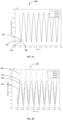
- the external leakage flux measurements from the magnetic sensors 110a, 110b, 110c and 110d vary with time in a uniform manner and as such, there is no air gap eccentricity deciphered from the plots 305, 310, 315, and 320.
- leakage reactance between the stator 104 and the rotor 102 also varies and thus external leakage flux measurements of the rotating machine 100 from some of the magnetic sensors (e.g., 110a, 110b) may deviate from other magnetic sensors (110c, 110d) to indicate this change in the air gap 106 of the rotating machine 100.
- dynamic eccentricity is a condition in the rotating machine 100 where the center of the rotor 102 is not at the center of rotation and position of the minimum radial air gap rotates with the rotor 102.
- the external leakage flux measurements fluctuates with the change in the air gap 106 due to the dynamic eccentricity.
- the external leakage flux measurements from the magnetic sensors 110a, 110b, 110c and 110d vary with time in a non-uniform manner. More specifically, the external leakage flux measurements from the magnetic sensor 110a show significant fluctuations in their maximum value and minimum value observed over a time period ( see, plot 365). For example, maximum values ( v max1 , v max2 , v max3 , ...) and minimum values ( v min1 , v min2 , v min3 , ...) of the external leakage flux measurements are not uniform as in the rotating machine 100 with a healthy air gap 106 shown in FIG. 3A .
- an air gap eccentricity condition of the rotating machine 100 is determined based on the moving average associated with each of the plurality of magnetic sensors 110a, 110b, 110c, 110d.
- a magnetic sensor e.g., magnetic sensor 110a
- the series of averages ( b 1 , b 2 , b 3 , .... b n ) of corresponding sections of the external leakage flux measurements received from another magnetic sensor e.g., magnetic sensor 110b
- the moving averages of two magnetic sensors i.e., magnetic sensors 110a, 110b
- slight variations in the moving averages may be acceptable due to relative positioning of the magnetic sensors on the rotating machine 100.
- the processor 202 is configured to further analyze the moving averages of each of the plurality of magnetic sensors 1 10a, 110b, 110c, and 110d to determine the type of eccentricity condition.
- the air gap eccentricity condition may be determined as one of: dynamic eccentricity, static eccentricity or mixed eccentricity.
- the air gap eccentricity condition is determined as a dynamic eccentricity when the dynamic index is greater than a dynamic eccentricity threshold value.
- the dynamic eccentricity threshold value is a customer settable value for identifying faults in the air gap 106 of the rotating machine 100.
- the dynamic eccentricity threshold value may be set to 0.2.
- the air gap eccentricity condition is determined as dynamic eccentricity in the air gap 106 of the rotating machine as shown below by equation (6).
- the dynamic index is less than the dynamic eccentricity threshold value ( e.g., 0.2)
- there exists no eccentricity condition in the air gap 106 of the rotating machine 100 as may be apparent from the equation (6) shown below.
- dynEcc n 1 , if dynIndex n > dynamic eccentricity thershold value 0 , otherwise
- the processor 202 is configured to determine a dynamic eccentricity severity level based on the dynamic index.
- a dynamic eccentricity severity level is shown below in equation (7).
- a control signal may be generated based on based on customer settable severity level of the fault for actuating a circuit breaker electrically coupled to the rotating machine 100. More specifically, the operator of the system 150 may specify the dynamic eccentricity severity level such that faults (i.e., air gap eccentricity conditions) in the rotating machine 100 above a specified value may trigger the circuit breaker circuit to disconnect the rotating machine 100 from other circuits to prevent catastrophic failures.
- faults i.e., air gap eccentricity conditions
- the processor 202 is configured to determine a plurality of flux density distributions based on the moving average for the external leakage flux measurements received from each of the plurality of magnetic sensors 110a, 110b, 110c, 110d. More specifically, a flux density distribution LF MA ( n, 1: S ) is determined based on the external leakage flux measurements from a magnetic sensor, for example, the magnetic sensor 110a.
- a least flux density distribution and a maximum flux distribution from the plurality of flux density distributions are identified as the first reference flux density distribution and the second reference flux density distribution. More specifically, the plurality of flux density distributions ( LF MA ( n ,1), LF MA ( n ,2), LF MA ( n, 3), LF MA ( n, 4)) from the plurality of magnetic sensors 110a, 110b, 110c, 110d, respectively, are compared against each other to identify the first reference flux density distribution (i.e., minValSensor ) and the second reference flux density distribution (i.e., maxValSensor ) which is represented by equation (8) shown below.
- minValSensor min LF MA n , 1 :
- S maxValSensor max LF MA n , 1 : S
- a plurality of flux density distribution distances are determined based on the plurality of flux density distributions. More specifically, a flux density distribution distance is determined between each of the plurality of flux density distributions and each of: the first reference flux density distribution ( minValSensor ) and the second reference flux density distribution ( minValSensor ) . As such, a flux density distribution distance between the first reference flux density distribution/second reference flux density distribution and each of the plurality of flux density distributions is determined based on the equation (9) shown below.
- the reference flux density distributions i.e., LF MA ( n,2 ) and LF MA ( n ,4)
- LF MA ( n,1 ) ,LF MA ( n,2 ) ,LF MA ( n, 3) , LF MA ( n, 4) are compared with each of the flux density distributions ( LF MA ( n,1 ) ,LF MA ( n,2 ) ,LF MA ( n, 3) , LF MA ( n, 4) to determine the distance values as represented below based on the first/second reference flux density distribution difference: (i.e.,distVal ( n, 1) least ,distVal ( n, 2) least ,distVal ( n, 3) least ,distVal ( n ,4) least ,distVal ( n ,1) max , distVal ( n, 2) max ,distVal (n ,3 ) max , distVal(n,4) max ), respectively.
- the plurality of flux density distribution distances may be normalized prior to further processing.
- each flux density distribution distance may be normalized by dividing the flux density distribution distance values with an average value.
- the average value may be determined based on moving averages determined from external leakage flux measurements received from the plurality of magnetic sensors 110a, 110b, 110c, and 110d.
- normalizing of the flux density distribution distance may be performed as shown below in equation (10).
- the processor 202 is further configured to determine a change in the normalized flux density distribution distance (i.e., delta norm) for each magnetic sensor with respect to the previous time instant (i.e., n-1 ) to determine the distribution difference.
- distDiff n , 1 : S least , max distValNorm n , 1 : S least , max ⁇ distValNorm n ⁇ 1,1 : S least , max
- the air gap eccentricity condition is determined as a static eccentricity when the static index statIndex ( n ) is greater than a static eccentricity threshold value.
- the processor 202 is configured to determine a static eccentricity severity level based on the normalized flux density distribution distValNorm ( n, 1 :S ) least,max .
- the static eccentricity level is a maximum value among the normalized distance value ( distValNorm ( n, 1) least ,distValNorm ( n, 2) least , distVdlNdrm ( n ,3) least , distValNorm ( n, 4) least , distValNorm ( n, 4) least , distValNorm ( n, 1) max ,distValNorm ( n ,2) max , distValNorm ( n, 4) max ) associated with distance between the reference flux density distributions ( LF MA ( n, 1:2) ,LF MA ( n, 4) ) and each of the other flux density distributions ( LF MA ( n,1 ) ,LF MA ( n,2 ) , LF MA ( n,3 ) , LF MA 4 (
- a control signal may be generated based on customer settable severity level of the static eccentricity for actuating a circuit breaker electrically coupled to the rotating machine 100. More specifically, the operator of the system 150 may specify the static eccentricity severity level such that faults (i.e., air gap eccentricity conditions) in the rotating machine 100 above a specified value may trigger the circuit breaker to disconnect the rotating machine 100 from other circuits to prevent catastrophic failures.
- faults i.e., air gap eccentricity conditions
- the rotating machine 100 may exhibit both static and dynamic eccentricity and in such cases, the air gap eccentricity condition is referred to as mixed eccentricity.
- type of eccentricity condition may be determined by evaluating the external leakage flux measurements from the plurality of magnetic sensors 1 10a, 1 10b, 110c, 1 10d for both dynamic eccentricity and static eccentricity.
- external leakage flux measurements of the rotating machine 100 is received from at least one magnetic sensor such as, the magnetic sensor 1 10a. It shall be noted that external leakage flux measurements from a single sensor would suffice to determine dynamic eccentricity as will be explained hereinafter. If external leakage flux measurements are received from more than one magnetic sensor, then the external leakage flux measurements from each of the magnetic sensors are evaluated separately to determine presence of dynamic eccentricity in the air gap 106 of the rotating machine 100.
- a moving average is determined for the external leakage flux measurements received from the at least one magnetic sensor 110a.
- the moving average is a series of averages for different sections of the external leakage flux measurements of the magnetic sensor (i.e., 110a) which are analyzed in smaller windows.
- a dynamic eccentricity severity level is determined based on the dynamic index.
- An example of determining the dynamic eccentricity severity level is shown in equation (7).
- the dynamic eccentricity severity level indicates a measurement of condition of the air gap eccentricity condition ( here, dynamic eccentricity) which may enable the operator of the system 100 to schedule maintenance and take timely actions.
- An example method of determining static eccentricity in the air gap 106 of the rotating machine 100 is explained next with reference to FIG. 4B .
- FIG. 4B is a flowchart illustrating a method 450 for determining static eccentricity in the rotating machine 100, in accordance with an embodiment of the present disclosure.
- external leakage flux measurements of the rotating machine 100 is received from each of the plurality of magnetic sensors 1 10a, 110b, 110c and 110d by a system such as, the system 150.
- a least flux density distribution from the plurality of flux density distributions is identified as a first reference flux density distribution and a maximum flux density distribution from the plurality of flux density distributions is identified as a second reference flux density distribution.
- a static index is determined based on the plurality of flux density distribution distances (see, operation 460) and the distribution difference as explained with reference to FIG. 2 .
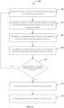
- FIG. 5 is a flowchart illustrating a method 500 for determining air gap eccentricity condition in a rotating machine, in accordance with an embodiment of the present disclosure.
- the method 500 depicted in the flow diagram may be executed by, for example, the processor 202 shown in FIG. 2 .
- Operations of the flow diagram, and combination of operations in the flow diagram may be implemented by, for example, hardware, firmware, a processor, circuitry and/or a different device associated with the execution of software that includes one or more computer program instructions.
- the operations of the method 500 are described herein with help of the processor 202 of the system 150. It is noted that the operations of the method 500 can be described and/or practiced by using one or more processors of a system/device other than the processor 202.
- the method 500 starts at operation 502
- external leakage flux measurements of a rotating machine 100 from each of a plurality of magnetic sensors 1 10a, 110b, 11c, 110d are received by a processor, such as, the processor 202 shown and explained with reference to FIG. 2 .
- the processor 302 may be embodied within a control system such as, a relay, capable of controlling the operations of an industrial process in which the rotating machine 120 is used.
- the system 150 is a control system controlling the rotating machine 120 or maybe configured as a standalone processor configured to perform one or more of the operations described herein.
- the processor 302 may be configured in a centralized/cloud applications, where it will receive external leakage flux measurements periodically and provide information about any evolving air gap eccentricity condition.
- the external leakage flux measurements are made external to the air gap 106 of the rotating machine 100 precluding the need for constructional changes which may be required in deploying the magnetic sensors 110a, 110b, 110c, 110d.
- a moving average is determined for the external leakage flux measurements received from each of the plurality of magnetic sensors. More specifically, the moving average is determined as a series of averages based on external leakage flux measurements from each magnetic sensor of the plurality of magnetic sensors 110a, 110b, 110c, 110d. In an embodiment, pre-processing may be performed on the external leakage flux measurements received from each magnetic sensor to generate the DC components of the external leakage flux measurements which may be processed further to detect air gap eccentricity and severity level of the air gap eccentricity in the rotating machine 100.
- an air gap eccentricity condition of the rotating machine is determined based on the moving average associated with each of the plurality of magnetic sensors. Any deviation in moving average beyond a predefined threshold, when compared within the series of average of the external leakage flux measurements associated with a magnetic sensors, such as, magnetic sensor 110a, indicates an air gap eccentricity. Similarly, any deviation in moving average when compared with moving averages of corresponding sections associated with external leakage flux measurement from another magnetic sensor (e.g., magnetic sensor 110b) indicate air gap eccentricity. Determining of the type of air gap eccentricity in the rotating machine 100 has been explained in detail with reference to FIGS. 2 and 4A-4B and is not explained herein for the sake of brevity.
- the type of air gap eccentricity condition and severity level of the air gap eccentricity condition may be displayed on the output interface (i.e., I/O module 206) or data (i.e., type of air gap eccentricity and severity level) related to the air gap eccentricity condition in the rotating machine 100 may also be sent to a remote server, for visualization and report generation, using a secure communication channel.
- sequence of operations of the methods 400, 450, and 500 need not be necessarily executed in the same order as they are presented. Further, one or more operations may be grouped together and performed in form of a single step, or one operation may have several sub-steps that may be performed in parallel or in sequential manner.
- Embodiments of the present disclosure provide numerous advantages.
- Embodiments of the present disclosure provide a method and system for air gap eccentricity detection in rotating machines. More specifically, system receives external leakage flux measurements from only non-intrusive external sensors which measure leakage flux generated external to the air gap of the rotating machine 100. More specifically, magnetic sensors already deployed in the machine for monitoring condition of the rotating machine 100 may be used without the need for any special constructional changes unlike the intrusive sensors placed in the air gap 106 of the rotating machine 100.
- the disclosed method uses signal processing techniques to detect eccentricity conditions, at the same time, differentiating it from non-eccentricity conditions like rotor short circuit and stator short circuit.
- the system may also be deployed in a centralized/cloud applications, where it will receive external leakage flux measurements periodically and provide information about any evolving air gap eccentricity conditions which may result in a fault and severity of the air gap eccentricity at a given time. Further, the severity level of the air gap eccentricity may also be determined, which will help users/operators to take corrective steps well in time before the condition deteriorates. Moreover, as external leakage flux measurements are analyzed using signal processing techniques, the amount of computational resources consumed to determine the air gap eccentricity is significantly reduced when compared to the complex frequency spectrum analysis which are computationally intensive consuming significant memory and processing resources.
Landscapes
- Physics & Mathematics (AREA)
- General Physics & Mathematics (AREA)
- Manufacture Of Motors, Generators (AREA)
Applications Claiming Priority (1)
| Application Number | Priority Date | Filing Date | Title |
|---|---|---|---|
| IN202341066285 | 2023-10-03 |
Publications (1)
| Publication Number | Publication Date |
|---|---|
| EP4535018A1 true EP4535018A1 (fr) | 2025-04-09 |
Family
ID=92926036
Family Applications (1)
| Application Number | Title | Priority Date | Filing Date |
|---|---|---|---|
| EP24202748.0A Pending EP4535018A1 (fr) | 2023-10-03 | 2024-09-26 | Procédé et système de détection d'excentricité d'entrefer dans des machines rotatives |
Country Status (2)
| Country | Link |
|---|---|
| EP (1) | EP4535018A1 (fr) |
| CN (1) | CN119756159A (fr) |
Citations (2)
| Publication number | Priority date | Publication date | Assignee | Title |
|---|---|---|---|---|
| EP2653836A1 (fr) * | 2012-04-19 | 2013-10-23 | ABB Research Ltd. | Dispositif et procédé pour surveiller une excentricité ou un petit entrefer d'une machine électrique rotative |
| CN110531259A (zh) * | 2019-08-12 | 2019-12-03 | 西安交通大学 | 基于漏磁信号的感应电机电气故障诊断方法 |
-
2024
- 2024-09-26 EP EP24202748.0A patent/EP4535018A1/fr active Pending
- 2024-09-27 CN CN202411358961.XA patent/CN119756159A/zh active Pending
Patent Citations (2)
| Publication number | Priority date | Publication date | Assignee | Title |
|---|---|---|---|---|
| EP2653836A1 (fr) * | 2012-04-19 | 2013-10-23 | ABB Research Ltd. | Dispositif et procédé pour surveiller une excentricité ou un petit entrefer d'une machine électrique rotative |
| CN110531259A (zh) * | 2019-08-12 | 2019-12-03 | 西安交通大学 | 基于漏磁信号的感应电机电气故障诊断方法 |
Non-Patent Citations (2)
| Title |
|---|
| BERNIER SIMON ET AL: "Stray flux and air gap flux experimental measurement and analysis in large hydro generators", 2023 IEEE WORKSHOP ON ELECTRICAL MACHINES DESIGN, CONTROL AND DIAGNOSIS (WEMDCD), IEEE, 13 April 2023 (2023-04-13), pages 1 - 6, XP034337268, DOI: 10.1109/WEMDCD55819.2023.10110944 * |
| VITEK O ET AL: "Detection of eccentricity and bearings fault using stray flux monitoring", DIAGNOSTICS FOR ELECTRIC MACHINES, POWER ELECTRONICS&DRIVES (SDEMPED), 2011 IEEE INTERNATIONAL SYMPOSIUM ON, IEEE, 5 September 2011 (2011-09-05), pages 456 - 461, XP032067913, ISBN: 978-1-4244-9301-2, DOI: 10.1109/DEMPED.2011.6063663 * |
Also Published As
| Publication number | Publication date |
|---|---|
| CN119756159A (zh) | 2025-04-04 |
Similar Documents
| Publication | Publication Date | Title |
|---|---|---|
| US12510403B2 (en) | Systems and methods for monitoring of mechanical and electrical machines | |
| KR102219090B1 (ko) | 발전기의 고장예측 진단 시스템 | |
| US9910093B2 (en) | Generator neutral ground monitoring device utilizing direct current component measurement and analysis | |
| US9803618B2 (en) | Monitoring and fault prediction in relation to a mechanical component of a rotating system | |
| KR102208830B1 (ko) | 모터펌프의 모니터링 장치 및 방법 | |
| US9076321B2 (en) | Real time control chart generation and monitoring of safety systems | |
| US20260043711A1 (en) | Methods and systems for monitoring, diagnosis and prediction of health of an industrial machine having a rotating component | |
| JP6431656B2 (ja) | 電気システムの調子をモニタするためのシステムおよび方法 | |
| CN103261904A (zh) | 电动机器的监测和故障诊断 | |
| CN120353683A (zh) | 一种存储芯片高低温老化试验箱故障自诊断系统、方法和计算机设备 | |
| EP3260874B1 (fr) | Systèmes et procédés pour déterminer la détérioration de rotor d'une machine dynamoélectrique | |
| EP4535018A1 (fr) | Procédé et système de détection d'excentricité d'entrefer dans des machines rotatives | |
| CN118060512A (zh) | 连铸机控制方法、连铸机控制系统及计算机可读存储介质 | |
| US12255568B2 (en) | Monitoring circuit for electrical motor space heaters | |
| JP6243940B2 (ja) | 風力発電システムの異常予兆診断システム | |
| US20200122859A1 (en) | Predictive monitoring system and method | |
| US20060267594A1 (en) | Power generation unit condition monitor using frequency profile analysis | |
| CN113884876B (zh) | 故障检测系统及方法 | |
| CN108151795A (zh) | 用于配置状态监测装置的方法及系统 | |
| CN109425479B (zh) | 一种故障预警方法和装置 | |
| WO2022263016A1 (fr) | Procédé et appareil de détection de défaillance de palier de moteur utilisant un courant détecté | |
| CN118191590A (zh) | 发电机励磁系统在线监测系统 | |
| WO2011126110A1 (fr) | Système de prédiction de tremblement de terre, programme de prédiction de tremblement de terre, et procédé de prédiction de tremblement de terre |
Legal Events
| Date | Code | Title | Description |
|---|---|---|---|
| PUAI | Public reference made under article 153(3) epc to a published international application that has entered the european phase |
Free format text: ORIGINAL CODE: 0009012 |
|
| STAA | Information on the status of an ep patent application or granted ep patent |
Free format text: STATUS: REQUEST FOR EXAMINATION WAS MADE |
|
| 17P | Request for examination filed |
Effective date: 20240926 |
|
| AK | Designated contracting states |
Kind code of ref document: A1 Designated state(s): AL AT BE BG CH CY CZ DE DK EE ES FI FR GB GR HR HU IE IS IT LI LT LU LV MC ME MK MT NL NO PL PT RO RS SE SI SK SM TR |