EP3260939A1 - Drahtloses flugzeugmotorüberwachungssystem - Google Patents
Drahtloses flugzeugmotorüberwachungssystem Download PDFInfo
- Publication number
- EP3260939A1 EP3260939A1 EP17176086.1A EP17176086A EP3260939A1 EP 3260939 A1 EP3260939 A1 EP 3260939A1 EP 17176086 A EP17176086 A EP 17176086A EP 3260939 A1 EP3260939 A1 EP 3260939A1
- Authority
- EP
- European Patent Office
- Prior art keywords
- engine
- nacelle
- antenna
- composite panel
- data
- Prior art date
- Legal status (The legal status is an assumption and is not a legal conclusion. Google has not performed a legal analysis and makes no representation as to the accuracy of the status listed.)
- Granted
Links
Images





Classifications
-
- G—PHYSICS
- G05—CONTROLLING; REGULATING
- G05B—CONTROL OR REGULATING SYSTEMS IN GENERAL; FUNCTIONAL ELEMENTS OF SUCH SYSTEMS; MONITORING OR TESTING ARRANGEMENTS FOR SUCH SYSTEMS OR ELEMENTS
- G05B19/00—Program-control systems
- G05B19/02—Program-control systems electric
- G05B19/04—Program control other than numerical control, i.e. in sequence controllers or logic controllers
- G05B19/042—Program control other than numerical control, i.e. in sequence controllers or logic controllers using digital processors
-
- H—ELECTRICITY
- H01—ELECTRIC ELEMENTS
- H01Q—ANTENNAS, i.e. RADIO AERIALS
- H01Q1/00—Details of, or arrangements associated with, antennas
- H01Q1/27—Adaptation for use in or on movable bodies
- H01Q1/28—Adaptation for use in or on aircraft, missiles, satellites, or balloons
-
- B—PERFORMING OPERATIONS; TRANSPORTING
- B64—AIRCRAFT; AVIATION; COSMONAUTICS
- B64C—AEROPLANES; HELICOPTERS
- B64C7/00—Structures or fairings not otherwise provided for
- B64C7/02—Nacelles
-
- B—PERFORMING OPERATIONS; TRANSPORTING
- B64—AIRCRAFT; AVIATION; COSMONAUTICS
- B64D—EQUIPMENT FOR FITTING IN OR TO AIRCRAFT; FLIGHT SUITS; PARACHUTES; ARRANGEMENT OR MOUNTING OF POWER PLANTS OR PROPULSION TRANSMISSIONS IN AIRCRAFT
- B64D29/00—Power-plant nacelles, fairings or cowlings
-
- B—PERFORMING OPERATIONS; TRANSPORTING
- B64—AIRCRAFT; AVIATION; COSMONAUTICS
- B64D—EQUIPMENT FOR FITTING IN OR TO AIRCRAFT; FLIGHT SUITS; PARACHUTES; ARRANGEMENT OR MOUNTING OF POWER PLANTS OR PROPULSION TRANSMISSIONS IN AIRCRAFT
- B64D29/00—Power-plant nacelles, fairings or cowlings
- B64D29/06—Attaching of nacelles, fairings or cowlings
-
- B—PERFORMING OPERATIONS; TRANSPORTING
- B64—AIRCRAFT; AVIATION; COSMONAUTICS
- B64F—GROUND OR AIRCRAFT-CARRIER-DECK INSTALLATIONS SPECIALLY ADAPTED FOR USE IN CONNECTION WITH AIRCRAFT; DESIGNING, MANUFACTURING, ASSEMBLING, CLEANING, MAINTAINING OR REPAIRING AIRCRAFT, NOT OTHERWISE PROVIDED FOR; HANDLING, TRANSPORTING, TESTING OR INSPECTING AIRCRAFT COMPONENTS, NOT OTHERWISE PROVIDED FOR
- B64F5/00—Designing, manufacturing, assembling, cleaning, maintaining or repairing aircraft, not otherwise provided for; Handling, transporting, testing or inspecting aircraft components, not otherwise provided for
- B64F5/60—Testing or inspecting aircraft components or systems
-
- G—PHYSICS
- G01—MEASURING; TESTING
- G01M—TESTING STATIC OR DYNAMIC BALANCE OF MACHINES OR STRUCTURES; TESTING OF STRUCTURES OR APPARATUS, NOT OTHERWISE PROVIDED FOR
- G01M15/00—Testing of engines
- G01M15/14—Testing gas-turbine engines or jet-propulsion engines
-
- G—PHYSICS
- G07—CHECKING-DEVICES
- G07C—TIME OR ATTENDANCE REGISTERS; REGISTERING OR INDICATING THE WORKING OF MACHINES; GENERATING RANDOM NUMBERS; VOTING OR LOTTERY APPARATUS; ARRANGEMENTS, SYSTEMS OR APPARATUS FOR CHECKING NOT PROVIDED FOR ELSEWHERE
- G07C5/00—Registering or indicating the working of vehicles
- G07C5/008—Registering or indicating the working of vehicles communicating information to a remotely located station
-
- H—ELECTRICITY
- H01—ELECTRIC ELEMENTS
- H01Q—ANTENNAS, i.e. RADIO AERIALS
- H01Q1/00—Details of, or arrangements associated with, antennas
- H01Q1/27—Adaptation for use in or on movable bodies
- H01Q1/28—Adaptation for use in or on aircraft, missiles, satellites, or balloons
- H01Q1/286—Adaptation for use in or on aircraft, missiles, satellites, or balloons substantially flush mounted with the skin of the craft
-
- B—PERFORMING OPERATIONS; TRANSPORTING
- B64—AIRCRAFT; AVIATION; COSMONAUTICS
- B64D—EQUIPMENT FOR FITTING IN OR TO AIRCRAFT; FLIGHT SUITS; PARACHUTES; ARRANGEMENT OR MOUNTING OF POWER PLANTS OR PROPULSION TRANSMISSIONS IN AIRCRAFT
- B64D45/00—Aircraft indicators or protectors not otherwise provided for
- B64D2045/0085—Devices for aircraft health monitoring, e.g. monitoring flutter or vibration
-
- F—MECHANICAL ENGINEERING; LIGHTING; HEATING; WEAPONS; BLASTING
- F05—INDEXING SCHEMES RELATING TO ENGINES OR PUMPS IN VARIOUS SUBCLASSES OF CLASSES F01-F04
- F05D—INDEXING SCHEME FOR ASPECTS RELATING TO NON-POSITIVE-DISPLACEMENT MACHINES OR ENGINES, GAS-TURBINES OR JET-PROPULSION PLANTS
- F05D2260/00—Function
- F05D2260/80—Diagnostics
-
- G—PHYSICS
- G05—CONTROLLING; REGULATING
- G05B—CONTROL OR REGULATING SYSTEMS IN GENERAL; FUNCTIONAL ELEMENTS OF SUCH SYSTEMS; MONITORING OR TESTING ARRANGEMENTS FOR SUCH SYSTEMS OR ELEMENTS
- G05B2219/00—Program-control systems
- G05B2219/30—Nc systems
- G05B2219/33—Director till display
- G05B2219/33192—Radio link, wireless
Definitions
- the field of the disclosure relates generally to aircraft engine monitoring, and more particularly, to aircraft engine diagnostics, including the usage of an antenna embedded composite panel that wirelessly facilitates transmission of engine data through a nacelle.
- nacelle that protects the complex engine components from foreign objects that include flying debris and birds.
- the nacelle also provides an aerodynamic fairing for the aircraft engine and provides a flow path for engine thrust.
- minimizing weight is crucial in aircraft and nacelle construction, and many known nacelles are manufactured with aluminum or a carbon fiber reinforced polymer material that is light-weight, durable, strong, and capable of meeting the structural and functional requirements of the aircraft propulsion system, including protecting and supporting the weight of the engine.
- materials such as aluminum and carbon fiber-reinforced polymer highly attenuate radio and wireless signals, and thus, it remains difficult to wirelessly and directly transmit and receive engine data to/from outside the nacelle through these types of materials.
- an engine monitoring system for an aircraft engine has a nacelle extending annularly thereabout and includes at least one sensor positioned radially inward from the nacelle.
- the system includes an engine control device communicatively coupled to the at least one sensor.
- the engine control device is configured to at least one of receive engine data from the at least one sensor and receive instruction data from a transmitter device positioned radially outward from a radially outward surface of the nacelle.
- the system also includes a composite panel including at least a portion of the nacelle and a ground plane positioned radially inward from a radially outward surface of the nacelle and an antenna communicatively coupled to the engine control device.
- the antenna is configured to at least one of receive the engine data from the engine control device and to transmit the engine data to a receiver device positioned radially outward from the radially outward surface of the nacelle, and receive the instruction data from the transmitter device and to transmit the instruction data to the engine control device.
- the composite panel further includes a radome positioned radially outward from the ground plane.
- a composite panel for monitoring an aircraft engine includes a nacelle extending annularly thereabout, at least one sensor positioned radially inward from the nacelle, and an engine control device communicatively coupled to the at least one sensor.
- the engine control device is configured to at least one of receive engine data from the at least one sensor and receive instruction data from a transmitter device positioned radially outward from a radially outward surface of the nacelle.
- the composite panel includes at least a portion of the nacelle and a ground plane positioned radially inward from the radially outward surface of the at least a portion of the nacelle.
- the composite panel also includes an antenna communicatively coupled to the engine control device.
- the antenna is configured to at least one of receive the engine data from the engine control device and to transmit the engine data to a receiver device positioned radially outward from the radially outward surface of the nacelle, and receive the instruction data from the transmitter device and to transmit the instruction data to the engine control device.
- the composite panel further includes a radome positioned radially outward from the ground plane.
- an aircraft in yet another aspect, includes an aircraft engine having a nacelle extending annularly thereabout.
- the aircraft engine also includes at least one sensor positioned radially inward from the nacelle and an engine control device communicatively coupled to the at least one sensor.
- the engine control device is configured to at least one of receive engine data from the at least one sensor and receive instruction data from a transmitter device positioned radially outward from a radially outward surface of the nacelle.
- the aircraft engine also includes a composite panel including at least a portion of the nacelle and a ground plane positioned radially inward from the radially outward surface of the nacelle.
- the composite panel also includes an antenna communicatively coupled to the engine control device.
- the antenna is configured to at least one of receive the engine data from the engine control device and to transmit the engine data to a receiver device positioned radially outward from the radially outward surface of the nacelle, and receive the instruction data from the transmitter device and to transmit the instruction data to the engine control device.
- the composite panel further includes a radome positioned radially outward from the ground plane.
- Approximating language is applied to modify any quantitative representation that could permissibly vary without resulting in a change in the basic function to which it is related. Accordingly, a value modified by a term or terms, such as “about”, “approximately”, and “substantially”, are not to be limited to the precise value specified. In at least some instances, the approximating language may correspond to the precision of an instrument for measuring the value.
- range limitations are combined and interchanged, such ranges are identified and include all the sub-ranges contained therein unless context or language indicates otherwise.
- processor and “computer,” and related terms, e.g., “processing device,” “computing device,” and “controller” are not limited to just those integrated circuits referred to in the art as a computer, but broadly refers to a microcontroller, a microcomputer, a programmable logic controller (PLC), and application specific integrated circuit, and other programmable circuits, and these terms are used interchangeably herein.
- memory may include, but it not limited to, a computer-readable medium, such as a random access memory (RAM), a computer-readable non-volatile medium, such as a flash memory.
- additional input channels may be, but are not limited to, computer peripherals associated with an operator interface such as a mouse and a keyboard.
- computer peripherals may also be used that may include, for example, but not be limited to, a scanner.
- additional output channels may include, but not be limited to, an operator interface monitor.
- the terms "software” and “firmware” are interchangeable, and include any computer program storage in memory for execution by personal computers, workstations, clients, and servers.
- non-transitory computer-readable media is intended to be representative of any tangible computer-based device implemented in any method of technology for short-term and long-term storage of information, such as, computer-readable instructions, data structures, program modules and sub-modules, or other data in any device. Therefore, the methods described herein may be encoded as executable instructions embodied in a tangible, non-transitory, computer-readable medium, including, without limitation, a storage device and/or a memory device. Such instructions, when executed by a processor, cause the processor to perform at least a portion of the methods described herein.
- non-transitory computer-readable media includes all tangible, computer-readable media, including, without limitation, non-transitory computer storage devices, including without limitation, volatile and non-volatile media, and removable and non-removable media such as firmware, physical and virtual storage, CD-ROMS, DVDs, and any other digital source such as a network or the Internet, as well as yet to be developed digital means, with the sole exception being transitory, propagating signal.
- the monitoring systems described herein wirelessly, through a nacelle, facilitate the measurement of one or more environmental or engine conditions experienced by an engine during operation or non-operation.
- the one or more environmental conditions experienced by an aircraft engine include temperature, dust, vibration, chemical contamination, heat expansion, and strain of various components, such as rotary brackets, fuel lines, and other components of the engine.
- the monitoring system measures and records aspects of engine performance, such as thrust, air intake, and fuel usage and efficiency. These measurements are stored as engine data for later use and to assist maintenance crews and engineers in identifying repairs and other maintenance activities that need to be performed on an aircraft engine (e.g., a component of an aircraft engine from which an abnormal amount of vibration was detected during flight).
- engine data may refer to not only environmental condition measurements but also, for example and without limitation, engine manufacturer, model, or any other specifications relating to the engine.
- the system described herein advantageously includes an antenna embedded within a composite panel configured to couple or attach to the nacelle.
- the embedded antenna composite panel is communicatively coupled to an engine control device that is coupled to the engine and configured to acquire engine data.
- the antenna embedded in the composite panel facilitates the transmission of engine data from the engine control device from within the nacelle to a receiver host without a technician having to open the nacelle or to physically access the engine through a service door.
- This configuration reduces the amount of time and resources expended in aircraft engine maintenance because engine data may be quickly and efficiently downloaded through the use of a mobile device that is proximate to the nacelle.
- the engine data may also be downloaded through the use of a cellular network or other ground based wireless communication system, such as WiFi.
- the antenna embedded in the composite panel further facilitates wireless transmission of environmental condition data and monitored engine operating conditions, for example and without limitation, status signals transmitted to pilots about whether or not aircraft engine cowl latches are fully secured, and operational parameters of secondary structure of the aircraft engine including, without limitation, vibrations of the pylon, nacelle, and the reverser.
- engine data includes information, including sensor-acquired data, facilitating health monitoring of aircraft engine rotating components such as fans, and other non-rotating engine components including various devices and systems (e.g., reverser actuators) mounted to the nacelle and the fan case. Therefore, such integration of an antenna embedded within a composite panel coupled to a nacelle allows for more robust, cheaper, and faster engine data acquisition.
- the antenna embedded in the composite panel facilitates receiving instructions (e.g., instruction data) from an operator or associated system about which engine parameters to save.
- instructions e.g., instruction data
- an engine control device receives instruction data for the scheduled flight communicated through the antenna embedded in the composite panel on the nacelle.
- the engine control device will save these parameters during flight and at the end of the flight, i.e., when the aircraft is on the ground, and the data associated with these parameters is transmitted to the user through the antenna embedded in the composite panel.
- the antenna embedded in the composite panel enables receipt of user-initiated software updates for the engine control device and associated systems.
- embedded antenna is enabled to function as a transceiver in addition to one of a receiver and a transmitter.
- FIG. 1 is an exploded schematic view of an engine monitoring system 100 that includes an engine 102 coupled to an engine control device 104, for example and without limitation, a sensor monitoring unit, a controller, or any other similar device enclosed within a nacelle 110.
- engine 102 is embodied in an aircraft engine for an aircraft 101.
- Engine 102 includes a centerline C defining forward and aft axial directions A.
- engine 102 is any other turbomachine, including, without limitation, a steam turbine engine, an aircraft engine, a wind turbine, and a compressor.
- engine 102 includes a fan 103, and a compressor section (not shown) that is coupled downstream from (i.e., aft), and in flow communication with fan 103.
- nacelle 110 includes at least two fan cowls 106 that have one or more service doors 108 that may include, for example and without limitation, a sensor panel door, oil door, pressure release door, or any other type of door generally situated within nacelle 110.
- these service doors 108 maybe retrofitted with a composite panel that includes an embedded antenna (described below) or may be embedded into the structure of at least one of fan cowl 106 (including external portions of surfaces thereof), other external surfaces of nacelle 110, and external surfaces of a pylon (not shown) at the time of manufacturing (also described below).
- Nacelle 110 further defines a circumferential and radially outward-most surface 111 (i.e., boundary) of engine 102, where substantially all components of engine 102 and engine monitoring system 100 are positioned radially inward from nacelle 110 to centerline C in a radial direction R, and where a forward portion of nacelle 110 and an inlet housing 112 defines an air inlet flowpath 114 for fan 103.
- Inlet housing 112 also contains one or more additional service doors 113 and one or more inlet sensors 116 (e.g., at least one of a temperature sensor and a pressure sensor) positioned under the one or more additional service doors 113.
- Inlet sensors 116 and other types of sensors are, in operation, placed at various locations within engine 102 where they at least one of detect, measure, record, display, report, transmit, and store engine data related to engine 102 performance including, without limitation, while engine 102 is running.
- at least one of engine control device 104, inlet sensors 116, and other types of sensors is operatively coupled to at least one control-related engine component (not shown) including, without limitation, valve actuators, fan blade pitch actuators, pumps (e.g., for fuel and coolant), and the like, and thereby facilitate control of engine 102 operating parameters.
- engine data acquired by inlet sensors 116 and other types of sensors is transmitted to engine control unit 104, and engine control unit 104 further transmits the engine data to embedded antenna.
- at least one of inlet sensors 116 and other sensor types transmit engine data directly to embedded antenna.
- a first type of engine data representative of operating conditions of engine 102 is transmitted from at least one of inlet sensors 116 and other sensor types directly to embedded antenna, and a second type of engine data is first transmitted from at least one of inlet sensors 116 and other sensor types to engine control unit 104.
- at least one of inlet sensors 116 and other types of sensors are configured to receive data from at least one of engine control unit 104 and embedded antenna.
- At least one of inlet sensor 116 and other sensor types includes a sensor capable of at least one of detecting, measuring, recording, displaying, reporting, transmitting, and storing a plurality of engine 102 operational parameters.
- a user of engine monitoring system 100 transmits instruction data to and through embedded antenna to at least one of engine control device 104, inlet sensors 116, and other sensor types to establish which at least one of the plurality of engine 102 operational parameters to employ the multi-parameter sensor for.
- embedded antenna is embodied in a transceiver.
- embedded antenna is also positioned beneath additional service door 113 and at least one of inlet sensors 116 and other sensor types is incorporated into embedded antenna.
- At least one of service door 108 and additional service door 113 houses beneath it at least one of a PNA1 access panel and a transcowl actuator fitting access panel.
- engine control device 104 includes a radio (not shown) coupled to the embedded antenna in nacelle 110 (described below) and configured to generate radio frequency waveforms appropriate to a communication protocol used in engine monitoring system 100. Radio is coupled to embedded antenna through a radio frequency transmission medium, examples of which include, without limitation, a coaxial cable, a twisted pair, and a transmission line.
- FIG. 2 is a schematic perspective view of an exemplary antenna embedded composite panel 208 affixed to fan cowl 106 of nacelle 110 (shown in FIG. 1 ) that may utilized in facilitating the wireless transmission of engine data.
- FIG. 2 depicts the exterior surface of fan cowl 106 and the radiating side of antenna embedded composite panel 208.
- antenna embedded composite panel 208 is constructed of a material that highly attenuates wireless signals, antenna embedded composite panel 208 facilitates the propagation of wireless signals in conjunction with engine control device 104.
- antenna embedded composite panel 208 is coupled to a support flange 209 of fan cowl 106 using a plurality of panel fasteners 210, for example and without limitation, screws, bolts, rivets, or any other means of affixing antenna embedded composite panel 208 to fan cowl 106 in a removable fashion.
- Support flange 209 is affixed to fan cowl 106 by a plurality of flange fasteners 212, such as and without limitation, rivets, screws, and bolts, thus facilitating removal of antenna embedded composite panel 208 from the exterior of engine 102.
- antenna embedded composite panel 208 is affixed to fan cowl 106 through at least one hinge (not shown).
- antenna embedded composite panel 208 is not affixed to fan cowl 106 of nacelle 110, but rather is positioned on other portions of engine 102 including, without limitation, an inlet outer barrel, a thumbnail fairing, and a reverser trans cowl.
- at least one of the inlet outer barrel, the thumbnail fairing, and the reverser transcowl includes at least one of an access cover or a door used to house the antenna embedded composite panel 208.
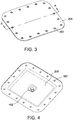
- FIGS. 3 and 4 are a schematic perspective top view and a bottom view, respectively, of antenna embedded composite panel 208 that is not affixed to fan cowl 106 (or otherwise nacelle 110) constructed of a material that highly attenuates wireless signals.
- Antenna embedded composite panel 208 includes fastener holes 302 that facilitate coupling of antenna embedded composite panel 208 to fan cowl 106.
- An antenna connector 402 facilitates at least one of a transmitter device and a receiver device (not shown) to electronically and communicatively couple to antenna embedded composite panel 208.
- Antenna connector 402 includes any type of antenna connector that allows a device to receive, transmit, or otherwise control the antenna embedded composite panel 208.
- antenna connector 402 may be configured to connect with coaxial cable to radio (not shown) on engine 102 or engine control device 104.
- FIG. 5 is a cross-sectional view of a portion of antenna embedded composite panel 208 as shown along line "A-A" (shown in FIG. 3 ).
- antenna embedded composite panel 208 includes antenna connector 402 and fastener holes 302 to attach antenna embedded composite panel 208 to support flange (not shown) of fan cowl 106.
- antenna embedded composite panel 208 includes a panel support structure 506 that encloses and supports embedded antenna structure 502.
- a material of construction of panel support structure 506 includes any number of composites, aluminum, or carbon fiber.
- a material of construction of panel support structure 506 includes radio frequency transparent materials of construction.
- antenna embedded composite panel 208 includes an embedded antenna structure 502, for example and without limitation, an antenna circuit board and a printed circuit board that facilitates transmission and reception of wireless signals and includes multiple layers as described below.
- Antenna embedded composite panel 208 also includes a radome structure 504 that protects embedded antenna structure 502 from physical damage and degradation.
- a material of construction of a radially outward surface 505 of radome structure 504 is the same as a material of construction of panel support structure 506 and radially outward surface 111 of engine 102, while in other embodiments, the radially outward surface 505 of radome structure 504 includes a different material of construction relative to at least one of panel support structure 506 and radially outward surface 111 of engine 102. Flying debris and environmental conditions such as precipitation, solar radiation damage, and ice may cause physical damage and degradation to the components of embedded antenna structure 502.
- the top or surface area of radially outward surface 505 of radome structure 504 is also advantageously shaped or molded to seamlessly fit the curves and surface of surrounding fan cowl 106.
- embedded antenna structure is configured to at least one of propagate (i.e., transmit) and receive at least one electromagnetic signal 508 through radome structure 504 to and from a receiver device 510 and a transmitter device 512, respectively, positioned radially outward from the radially outward surface 505 of radome structure 504.
- FIG. 6 is a cross-sectional view of a portion of the embedded antenna structure 502 shown in FIG. 5 .
- Embedded antenna structure 502 maybe constructed to implement any number of different types of antenna, for example and without limitation, a patch antenna, a microstrip antenna, a microstrip patch antenna, a planar inverted-F antenna, or any other suitable antenna.
- embedded antenna structure 502 may facilitate the transmission of engine data from engine control device 104 using any number of wireless communication protocols including, for example and without limitation, wireless local area network (WLAN), cellular protocol (e.g., Code Division Multiple Access (CDMA), LTE, Global System for Mobiles (GSM), etc.), WiMaxTM, BluetoothTM, or any other suitable wireless protocol.
- WLAN wireless local area network
- CDMA Code Division Multiple Access
- LTE Long Term Evolution
- GSM Global System for Mobiles
- WiMaxTM Wireless Fidelity
- embedded antenna structure 502 is configured to transmit the engine data at one or more frequency signals in combination with any number of wireless protocols.
- at least one of engine control device 104 (not shown) and embedded antenna structure 502 is configured to at least one of transmit and receive at least one the engine data and the instruction data over a predetermined range of a plurality of frequencies.
- embedded antenna structure 502 is also configured to receive signals at one or more frequencies including, without limitation, user instructions (e.g., instruction data) and software updates for engine control device 104 and associated devices used in engine monitoring system 100.
- FIG. 6 illustrates embedded antenna structure 502 for an exemplary patch antenna in which embedded antenna structure 502 includes a ground plane 602, a substrate layer 604, a radiating element 606, and a radome element 608. While only four layers are shown in FIG. 6 , any number of layers may be utilized and may be situated in any order that enables operation of embedded antenna structure 502 as described herein.
- a material of construction of ground plane 602 is a conductive metal such as copper (e.g., a standard circuit board ground plane).
- a material of construction of ground plane 602 is a carbon fiber-reinforced polymer material, including, without limitation, a polymer in combination with a metal such as copper.
- embedded antenna structure 502 includes radio frequency transparent materials of construction on both radially inward and radially outward surfaces of embedded antenna structure 502, where such other embodiments do not include ground plane 602.
- ground plane 602 may flank a panel support structure 506 located radially inward from nacelle 110 (i.e., closer to engine 102).
- Ground plane 602 provides a reflecting surface for radiating element 606.
- Substrate layer 604 is constructed from any type of dielectric material including, for example and without limitation, FR-4 (glass epoxy), bakelite, Rogers RO4003, Taconic TLC, RT Duroid, or any other suitable dielectric material.
- Ground plane 602 may be positioned in a direction toward engine 102 or situated in a location closest to engine 102.
- Substrate layer 604 can be designed for any type of radio wavelength and can vary in thickness.
- Radiating element 606 may include a patch or sheet of metal, a microstrip extending to the patch, or any other suitable type of antenna.
- the shape of the patch may be square, circular, or any suitable shape and the thickness of the antenna may vary.
- Radome element 608 may be constructed from, for example and without limitation, fiberglass, plastic (e.g., polycarbonate, acrylic), TeflonTM, laminate, or any other suitable radio frequency transparent material to facilitate transmission and receipt of radio frequency signals to and from, respectively, embedded antenna structure 502 including, without limitation, radio frequency signals carrying at least one of engine data and instruction data.
- radome element 608 and radome structure 504 may be used in combination or alternatively, radome element 608 may not be present and radome structure 504 may be solely used.
- Radome structure 504 may be positioned in a direction extending away from engine 102 or situated in a location farthest away from engine 102.
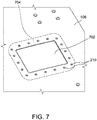
- FIG. 7 is a schematic perspective view of an alternative antenna embedded composite panel 702 affixed to fan cowl 106 of nacelle 110 that may utilized in facilitating wireless transmission of engine data.
- FIG. 7 depicts the exterior surface of fan cowl 106 and the radiating side of antenna embedded composite panel 702 that includes a different service door 108 shape and different coupling mechanism.
- antenna embedded composite panel 702 facilitates propagation of wireless signals in conjunction with engine control device 104.
- antenna embedded composite panel 702 is coupled to fan cowl 106 using panel fasteners 210, for example and without limitation, screws, bolts, rivets, or any other means of affixing antenna embedded composite panel 702 to fan cowl 106 in a removable fashion.
- Antenna embedded composite panel 702 includes a flange 704 that allows for panel fasteners 210 to assist in affixing antenna embedded composite panel 702 to fan cowl 106.
- flange 704 of antenna embedded composite panel 702 nests and is affixed by panel fasteners 210 to an interior surface of fan cowl 106, which facilitates a lighter weight implementation relative to the embodiment shown in FIG. 2 , but requires removal from the backside (i.e., radially inward side facing engine 102) of antenna embedded composite panel 702.
- FIG. 8 is a schematic perspective view of another alternative antenna embedded composite panel 802 affixed to fan cowl 106 of nacelle 110 that may be utilized in facilitating wireless transmission of engine data.
- FIG. 8 depicts the exterior surface of fan cowl 106 and the radiating side of antenna embedded composite panel 802 that includes a different service door 108 shape and different coupling mechanism.
- antenna embedded composite panel 802 facilitates the propagation of wireless signals in conjunction with engine control device 104.
- antenna embedded composite panel 802 is coupled to a supporting flange 804 of the fan cowl 106 using panel fasteners 210, for example and without limitation, screws, bolts, rivets, or any other means of affixing antenna embedded composite panel 802 to fan cowl 106 in a removable fashion.
- panel fasteners 210 for example and without limitation, screws, bolts, rivets, or any other means of affixing antenna embedded composite panel 802 to fan cowl 106 in a removable fashion.
- antenna embedded composite panel 802 is affixed to fan cowl 106 through at least one hinge (not shown), where antenna embedded composite panel 802 serves as an access door for other components of engine 102 including, without limitation, an oil tank access door.
- FIG. 9 is a schematic perspective view of yet another alternative antenna embedded composite panel 902 that is embedded or built into fan cowl 106 of nacelle 110 to facilitate wireless transmission of engine data.
- FIG. 9 depicts the exterior surface of fan cowl 106 and the radiating side of antenna embedded composite panel 902 that is embedded into fan cowl 106 during the manufacturing process.
- antenna embedded composite panel 902 facilitates the propagation of wireless signals in conjunction with engine control device 104. Because antenna embedded composite panel 902 is embedded into fan cowl 106 at the time of manufacturing, antenna embedded composite panel 902 does not require any fasteners allowing the panel support structure 506 to be seamlessly embedded with fan cowl 106.
- the monitoring systems described herein wirelessly facilitate, through a nacelle, the measurement of one or more environmental or engine conditions experienced by an engine during operation or non-operation.
- the one or more environmental conditions experienced by an aircraft engine include temperature, vibration, dust, chemical contamination, heat expansion, and strain of various components, such as rotary brackets, fuel lines, and other components of the engine.
- the monitoring system measures and records aspects of engine performance, such thrust, air intake, and fuel efficiency. These measurements assist maintenance crews and engineers in identifying repairs and other maintenance activities that need to be performed on an aircraft engine (e.g., a component of an aircraft engine from which an abnormal amount of vibration was detected during flight).
- engine data may refer to not only environmental condition measurements but also, for example and without limitation, engine manufacturer, model, or any other specifications relating to the engine.
- the system described herein advantageously includes an antenna embedded within a composite panel configured to couple or attach to the nacelle.
- the embedded antenna composite panel is communicatively coupled to an engine control device that is coupled to the engine and configured to acquire engine data.
- the antenna embedded in the composite panel facilitates the transmission of engine data from the engine control device from within the nacelle to a receiver host without a technician having to open the nacelle or to physically access the engine through a service door.
- This configuration reduces the amount of time and resources expended in aircraft engine maintenance because engine data may be quickly and efficiently downloaded through the use of a mobile device that is proximate to the nacelle.
- the engine data may also be downloaded through the use of a cellular network or other ground based wireless communication system such as WiFi. Therefore, such integration of an antenna embedded within a composite panel coupled to a nacelle allows for more robust, cheaper, timely, and faster engine data acquisition.
- An exemplary technical effect of the methods, systems, and apparatus described herein includes at least one of: (a) facilitating wireless transmission of environmental condition data, monitored engine operating conditions, and engine data, for example and without limitation, temperature, vibration, heat expansion, strain, chemical contamination, thrust, air intake, and fuel efficiency for an aircraft engine without physical inspection of a nacelle enclosure; (b) enabling the measurement of environmental and engine conditions regardless the material of which the nacelle is constructed; and (c) enabling more frequent and cheaper inspection of the aircraft engine which potentially decreases the frequency of maintenance and unscheduled repairs, and improves the service life of the aircraft engine.
- Exemplary embodiments of a monitoring system are described above in detail.
- the monitoring system and methods of manufacturing or operating such a system and device are not limited to the specific embodiments described herein, but rather, components of systems and/or steps of the methods may be utilized independently and separately from other components and/or steps described herein.
- the systems, apparatus, and methods may also be used in combination with other types of machines enclosed with materials that highly attenuated wireless signals, and are not limited to practice with only the monitoring system described herein.
- the exemplary embodiment can be implemented and utilized in connection with many other applications, equipment, and systems that may benefit from using antenna embedded composite panels.
- Some embodiments involve the use of one or more electronic or computing devices.
- Such devices typically include a processor, processing device, or controller, such as a general purpose central processing unit (CPU), a graphics processing unit (GPU), a microcontroller, a reduced instruction set computer (RISC) processor, an application specific integrated circuit (ASIC), a programmable logic circuit (PLC), a field programmable gate array (FPGA), a digital signal processing (DSP) device, and/or any other circuit or processing device capable of executing the functions described herein.
- the methods described herein may be encoded as executable instructions embodied in a computer readable medium, including, without limitation, a storage device and/or a memory device. Such instructions, when executed by a processing device, cause the processing device to perform at least a portion of the methods described herein.
- the above examples are exemplary only, and thus are not intended to limit in any way the definition and/or meaning of the term processor and processing device.
Landscapes
- Engineering & Computer Science (AREA)
- Aviation & Aerospace Engineering (AREA)
- Physics & Mathematics (AREA)
- General Physics & Mathematics (AREA)
- Astronomy & Astrophysics (AREA)
- Remote Sensing (AREA)
- Automation & Control Theory (AREA)
- Transportation (AREA)
- Manufacturing & Machinery (AREA)
- Chemical & Material Sciences (AREA)
- Combustion & Propulsion (AREA)
- Arrangements For Transmission Of Measured Signals (AREA)
- Details Of Aerials (AREA)
Applications Claiming Priority (1)
| Application Number | Priority Date | Filing Date | Title |
|---|---|---|---|
| US15/191,124 US9972896B2 (en) | 2016-06-23 | 2016-06-23 | Wireless aircraft engine monitoring system |
Publications (2)
| Publication Number | Publication Date |
|---|---|
| EP3260939A1 true EP3260939A1 (de) | 2017-12-27 |
| EP3260939B1 EP3260939B1 (de) | 2020-02-26 |
Family
ID=59070502
Family Applications (1)
| Application Number | Title | Priority Date | Filing Date |
|---|---|---|---|
| EP17176086.1A Active EP3260939B1 (de) | 2016-06-23 | 2017-06-14 | Drahtloses flugzeugmotorüberwachungssystem |
Country Status (5)
| Country | Link |
|---|---|
| US (1) | US9972896B2 (de) |
| EP (1) | EP3260939B1 (de) |
| JP (1) | JP6490149B2 (de) |
| CN (1) | CN107539484B (de) |
| CA (1) | CA2969962C (de) |
Cited By (10)
| Publication number | Priority date | Publication date | Assignee | Title |
|---|---|---|---|---|
| EP3726323A1 (de) * | 2019-04-17 | 2020-10-21 | United Technologies Corporation | Kommunikationsgateway für gasturbinenmotoren mit integrierten antennen |
| US10977877B2 (en) | 2019-04-17 | 2021-04-13 | Raytheon Technologies Corporation | Engine gateway with engine data storage |
| WO2021205126A1 (fr) * | 2020-04-10 | 2021-10-14 | Safran Nacelles | Organe d'obturation amovible pour une partie femelle logee dans une ouverture exterieure d'une nacelle de moteur d'aeronef |
| US11208916B2 (en) | 2019-04-17 | 2021-12-28 | Raytheon Technologies Corporation | Self-healing remote dynamic data recording |
| US11425200B2 (en) | 2019-04-17 | 2022-08-23 | Raytheon Technologies Corporation | Gas turbine engine communication gateway with internal sensors |
| US11441489B2 (en) | 2019-04-17 | 2022-09-13 | Raytheon Technologies Corporation | Remote updates of a gas turbine engine |
| US11492132B2 (en) | 2019-04-17 | 2022-11-08 | Raytheon Technologies Corporation | Gas turbine engine configuration data synchronization with a ground-based system |
| US11698031B2 (en) | 2019-04-17 | 2023-07-11 | Raytheon Technologies Corporation | Gas turbine engine with dynamic data recording |
| US11913643B2 (en) | 2019-04-17 | 2024-02-27 | Rtx Corporation | Engine wireless sensor system with energy harvesting |
| FR3154490A1 (fr) * | 2023-10-19 | 2025-04-25 | Safran Aircraft Engines | Dispositif de mesure de parametres physiques pour outillage de collage d’un panneau sur un carter |
Families Citing this family (15)
| Publication number | Priority date | Publication date | Assignee | Title |
|---|---|---|---|---|
| US20180319481A1 (en) * | 2017-05-05 | 2018-11-08 | Reed Chuda | Aircraft Spade Apparatus |
| US11424816B2 (en) | 2018-05-15 | 2022-08-23 | Pratt & Whitney Canada Corp. | Communication module for transmission of aircraft data |
| FR3084763B1 (fr) * | 2018-07-31 | 2020-08-14 | Safran Aircraft Engines | Systeme de controle de pieces d'un turboreacteur par identification radiofrequence |
| FR3084762B1 (fr) * | 2018-07-31 | 2020-08-14 | Safran Aircraft Engines | Systeme de controle de pieces d'un turboreacteur par identification radiofrequence avec antenne integree |
| US11286058B2 (en) * | 2018-12-18 | 2022-03-29 | Textron Innovations Inc. | Heliport docking system |
| US11085373B2 (en) * | 2019-01-31 | 2021-08-10 | Rolls-Royce North American Technologies Inc. | Gas turbine engine with mount for interchangeable inlets |
| KR102196398B1 (ko) * | 2019-12-16 | 2020-12-30 | (주)시스테크 | Gps 안테나가 장착된 덮개를 가진 드론 |
| CN112286098B (zh) * | 2020-10-29 | 2022-08-26 | 中国航发南方工业有限公司 | 转换板组件、燃气涡轮发电机组的数字电子控制装置 |
| CN114221721B (zh) * | 2021-12-10 | 2025-01-17 | 北京东方计量测试研究所 | 室内半空间无线电频谱监测系统及方法 |
| CN114132515A (zh) * | 2021-12-28 | 2022-03-04 | 河北福莱卡航空科技有限公司 | 飞行器监控、控制管理系统 |
| US12499717B2 (en) * | 2022-01-20 | 2025-12-16 | Pratt & Whitney Canada Corp. | Method and system for data transmission from an aircraft engine |
| US20240359804A1 (en) * | 2023-04-27 | 2024-10-31 | Spirit Aerosystems, Inc. | Fireproof swivel type access door for engine nacelle |
| EP4506242A1 (de) * | 2023-08-07 | 2025-02-12 | Rohr, Inc. | System zur erkennung des lastverlustwegs für eine flugzeugantriebssystemgondel und verfahren zur verwendung davon |
| CN117423980B (zh) * | 2023-12-18 | 2024-03-12 | 北京华龙通科技有限公司 | 一种集成油箱功能的机载下沉共形天线 |
| FR3160740B1 (fr) * | 2024-03-26 | 2026-03-20 | Safran Nacelles | Soufflante de turbomachine d’aéronef et son procédé d’utilisation |
Citations (5)
| Publication number | Priority date | Publication date | Assignee | Title |
|---|---|---|---|---|
| US5440300A (en) * | 1992-11-25 | 1995-08-08 | Simmonds Precision Products, Inc. | Smart structure with non-contact power and data interface |
| US20080054645A1 (en) * | 2006-09-06 | 2008-03-06 | Siemens Power Generation, Inc. | Electrical assembly for monitoring conditions in a combustion turbine operating environment |
| US20110133950A1 (en) * | 2007-11-08 | 2011-06-09 | Ramesh Subramanian | Instrumented component for wireless telemetry |
| US20110280279A1 (en) * | 2010-05-12 | 2011-11-17 | Gregory Otto J | Wireless temperature measurement system and methods of making and using same |
| US20140114549A1 (en) * | 2012-06-06 | 2014-04-24 | Harris Corporation | Wireless engine monitoring system with multiple hop aircraft communications capability and on-board processing of engine data |
Family Cites Families (37)
| Publication number | Priority date | Publication date | Assignee | Title |
|---|---|---|---|---|
| US3172110A (en) | 1961-04-21 | 1965-03-02 | Lockheed Aircraft Corp | Loop-coupled hf aircraft antenna |
| US4629146A (en) * | 1985-01-30 | 1986-12-16 | Rohr Industries, Inc. | Hold open rod for hinged section of nacelle system |
| US5184141A (en) * | 1990-04-05 | 1993-02-02 | Vought Aircraft Company | Structurally-embedded electronics assembly |
| FR2672438B1 (fr) | 1991-02-01 | 1993-09-17 | Alcatel Espace | Antenne reseau notamment pour application spatiale. |
| GB9116986D0 (en) * | 1991-08-07 | 1991-10-09 | Rolls Royce Plc | Gas turbine engine nacelle assembly |
| JPH0555607U (ja) * | 1991-12-24 | 1993-07-23 | 日立化成工業株式会社 | 車載用平面アンテナ装置 |
| US5437091A (en) * | 1993-06-28 | 1995-08-01 | Honeywell Inc. | High curvature antenna forming process |
| US6047925A (en) | 1993-07-01 | 2000-04-11 | The Boeing Company | Nose gear door integral composite glide slope antenna |
| US5646633A (en) * | 1995-04-05 | 1997-07-08 | Mcdonnell Douglas Corporation | Microstrip antenna having a plurality of broken loops |
| JPH11117811A (ja) * | 1997-10-14 | 1999-04-27 | Ishikawajima Harima Heavy Ind Co Ltd | 航空機用エンジン |
| US6198445B1 (en) * | 1999-12-29 | 2001-03-06 | Northrop Grumman Corporation | Conformal load bearing antenna structure |
| KR20040062589A (ko) * | 2001-10-26 | 2004-07-07 | 유니테크, 유한책임회사 | 코팅된 안테나 및 그 제작방법 |
| US20040206818A1 (en) * | 2001-12-03 | 2004-10-21 | Loda David C. | Engine-mounted microserver |
| US6943699B2 (en) * | 2003-07-23 | 2005-09-13 | Harris Corporation | Wireless engine monitoring system |
| FR2866070B1 (fr) * | 2004-02-05 | 2008-12-05 | Snecma Moteurs | Turboreacteur a fort taux de dilution |
| US7461444B2 (en) | 2004-03-29 | 2008-12-09 | Deaett Michael A | Method for constructing antennas from textile fabrics and components |
| US7109942B2 (en) | 2004-10-21 | 2006-09-19 | The Boeing Company | Structurally integrated phased array antenna aperture design and fabrication method |
| US7624951B1 (en) * | 2006-08-04 | 2009-12-01 | Hawker Beechcraft Corporation | Aircraft with antennas mounted on the tops and bottoms of aerodynamic-surface extensions |
| US8565998B2 (en) * | 2006-11-27 | 2013-10-22 | United Technologies Corporation | Gas turbine engine having on-engine data storage device |
| US8078354B2 (en) * | 2006-11-29 | 2011-12-13 | United Technologies Corporation | Global product management of a vehicle and a fleet of vehicles |
| US8604981B2 (en) | 2007-07-18 | 2013-12-10 | Times-7 Holdings Limited | Panel antenna and method of forming a panel antenna |
| US7628879B2 (en) | 2007-08-23 | 2009-12-08 | The Boeing Company | Conductive scrim embedded structural adhesive films |
| US8026857B2 (en) * | 2008-01-17 | 2011-09-27 | The Boeing Company | Wireless data communication and power transmission using aircraft structures having properties of an electromagnetic cavity |
| US7860664B2 (en) | 2008-04-15 | 2010-12-28 | Spirit Aerosystems, Inc. | System and method for self-contained structural health monitoring for composite structures |
| GB0816728D0 (en) * | 2008-09-15 | 2008-10-22 | Rolls Royce Plc | Improvements in or relating to engine monitoring and control |
| US8514136B2 (en) | 2009-10-26 | 2013-08-20 | The Boeing Company | Conformal high frequency antenna |
| US20130132035A1 (en) * | 2011-11-23 | 2013-05-23 | Ge Aviation Systems Llc | Method for diagnosing a health of an apparatus |
| US20130132034A1 (en) * | 2011-11-23 | 2013-05-23 | Ge Aviation Systems Llc | Method for prognosing a health problem of an apparatus |
| US8847823B2 (en) | 2012-01-09 | 2014-09-30 | Lockheed Martin Corporation | Dimensionally tolerant multiband conformal antenna arrays |
| US9026279B2 (en) * | 2012-06-06 | 2015-05-05 | Harris Corporation | Wireless engine monitoring system and configurable wireless engine sensors |
| US9614272B2 (en) | 2013-04-09 | 2017-04-04 | The Boeing Company | Aircraft antenna mounting system |
| US20150028160A1 (en) | 2013-06-01 | 2015-01-29 | John Gregory Roncz | Wingtip for a general aviation aircraft |
| JP5598879B2 (ja) * | 2013-07-11 | 2014-10-01 | 独立行政法人電子航法研究所 | 直線偏波の制御方法及びその装置 |
| US9873504B2 (en) * | 2013-10-18 | 2018-01-23 | Rohr, Inc. | Propulsion system nacelle with reduced number of external split lines |
| US9647331B2 (en) | 2014-04-15 | 2017-05-09 | The Boeing Company | Configurable antenna assembly |
| US10658758B2 (en) | 2014-04-17 | 2020-05-19 | The Boeing Company | Modular antenna assembly |
| CN204679200U (zh) * | 2015-05-14 | 2015-09-30 | 宁波吉利罗佑发动机零部件有限公司 | 发动机排气压力无线检测装置 |
-
2016
- 2016-06-23 US US15/191,124 patent/US9972896B2/en active Active
-
2017
- 2017-06-08 CA CA2969962A patent/CA2969962C/en active Active
- 2017-06-13 JP JP2017115537A patent/JP6490149B2/ja not_active Expired - Fee Related
- 2017-06-14 EP EP17176086.1A patent/EP3260939B1/de active Active
- 2017-06-23 CN CN201710486003.4A patent/CN107539484B/zh active Active
Patent Citations (5)
| Publication number | Priority date | Publication date | Assignee | Title |
|---|---|---|---|---|
| US5440300A (en) * | 1992-11-25 | 1995-08-08 | Simmonds Precision Products, Inc. | Smart structure with non-contact power and data interface |
| US20080054645A1 (en) * | 2006-09-06 | 2008-03-06 | Siemens Power Generation, Inc. | Electrical assembly for monitoring conditions in a combustion turbine operating environment |
| US20110133950A1 (en) * | 2007-11-08 | 2011-06-09 | Ramesh Subramanian | Instrumented component for wireless telemetry |
| US20110280279A1 (en) * | 2010-05-12 | 2011-11-17 | Gregory Otto J | Wireless temperature measurement system and methods of making and using same |
| US20140114549A1 (en) * | 2012-06-06 | 2014-04-24 | Harris Corporation | Wireless engine monitoring system with multiple hop aircraft communications capability and on-board processing of engine data |
Cited By (17)
| Publication number | Priority date | Publication date | Assignee | Title |
|---|---|---|---|---|
| US11549389B2 (en) | 2019-04-17 | 2023-01-10 | Raytheon Technologies Corporation | Gas turbine engine communication gateway with integral antennas |
| US11615653B2 (en) | 2019-04-17 | 2023-03-28 | Raytheon Technologies Corporation | Engine gateway with engine data storage |
| US12107923B2 (en) | 2019-04-17 | 2024-10-01 | Rtx Corporation | Gas turbine engine communication gateway with internal sensors |
| US11913643B2 (en) | 2019-04-17 | 2024-02-27 | Rtx Corporation | Engine wireless sensor system with energy harvesting |
| US11208916B2 (en) | 2019-04-17 | 2021-12-28 | Raytheon Technologies Corporation | Self-healing remote dynamic data recording |
| US11425200B2 (en) | 2019-04-17 | 2022-08-23 | Raytheon Technologies Corporation | Gas turbine engine communication gateway with internal sensors |
| US11441489B2 (en) | 2019-04-17 | 2022-09-13 | Raytheon Technologies Corporation | Remote updates of a gas turbine engine |
| US11492132B2 (en) | 2019-04-17 | 2022-11-08 | Raytheon Technologies Corporation | Gas turbine engine configuration data synchronization with a ground-based system |
| US10977877B2 (en) | 2019-04-17 | 2021-04-13 | Raytheon Technologies Corporation | Engine gateway with engine data storage |
| US11698031B2 (en) | 2019-04-17 | 2023-07-11 | Raytheon Technologies Corporation | Gas turbine engine with dynamic data recording |
| EP3726323A1 (de) * | 2019-04-17 | 2020-10-21 | United Technologies Corporation | Kommunikationsgateway für gasturbinenmotoren mit integrierten antennen |
| US11743338B2 (en) | 2019-04-17 | 2023-08-29 | Raytheon Technologies Corporation | Gas turbine engine communication gateway with internal sensors |
| US11746708B2 (en) | 2019-04-17 | 2023-09-05 | Raytheon Technologies Corporation | Remote updates of a gas turbine engine |
| US11898455B2 (en) | 2019-04-17 | 2024-02-13 | Rtx Corporation | Gas turbine engine communication gateway with integral antennas |
| FR3109142A1 (fr) * | 2020-04-10 | 2021-10-15 | Safran Nacelles | Organe d’obturation amovible pour une partie femelle logée dans une ouverture extérieure d’une nacelle d’aéronef |
| WO2021205126A1 (fr) * | 2020-04-10 | 2021-10-14 | Safran Nacelles | Organe d'obturation amovible pour une partie femelle logee dans une ouverture exterieure d'une nacelle de moteur d'aeronef |
| FR3154490A1 (fr) * | 2023-10-19 | 2025-04-25 | Safran Aircraft Engines | Dispositif de mesure de parametres physiques pour outillage de collage d’un panneau sur un carter |
Also Published As
| Publication number | Publication date |
|---|---|
| US20170369188A1 (en) | 2017-12-28 |
| CA2969962C (en) | 2020-06-16 |
| US9972896B2 (en) | 2018-05-15 |
| CN107539484A (zh) | 2018-01-05 |
| JP6490149B2 (ja) | 2019-03-27 |
| CA2969962A1 (en) | 2017-12-23 |
| CN107539484B (zh) | 2020-09-11 |
| EP3260939B1 (de) | 2020-02-26 |
| JP2018020765A (ja) | 2018-02-08 |
Similar Documents
| Publication | Publication Date | Title |
|---|---|---|
| EP3260939B1 (de) | Drahtloses flugzeugmotorüberwachungssystem | |
| US10093436B2 (en) | Wireless aircraft engine communication system | |
| US11061394B2 (en) | In-situ measurement logging by wireless communication unit for communicating engine data | |
| EP3418504A1 (de) | Verfahren zur zustandsüberwachung und gasturbinentriebwerk | |
| US10529150B2 (en) | Remote data loading for configuring wireless communication unit for communicating engine data | |
| EP3009906B1 (de) | Motorgesundheitsmanagementvorrichtung und verfahren | |
| JP5801771B2 (ja) | 補助動力装置の性能検出方法 | |
| US20160178464A1 (en) | Torque sensor monitoring for gas turbine engine | |
| US10819601B2 (en) | Wireless control unit server for conducting connectivity test | |
| US20140308124A1 (en) | Optimization of downstream open fan propeller position and placement of acoustic sensors | |
| EP4239282B1 (de) | System und verfahren zur inspektion des schaufelspitzenspiels in bezug auf ein abreibbares lüftergehäuse | |
| EP2899539B1 (de) | Verfahren zur Überprüfung der Gebläseschienenauskleidung einer Gasturbine | |
| Weir | Engine validation of noise and emission reduction technology phase I | |
| US20250179964A1 (en) | Variable bleed valve assemblies | |
| US10467016B2 (en) | Managing an image boot | |
| Mironov et al. | Predictive vibration diagnostics of helicopter rotating units in field conditions | |
| US20180002040A1 (en) | Data load connectivity test for wireless communication unit for communicating engine data | |
| Koch | Quiet, efficient fans for spacecraft: An overview of NASA's Technology Development Plan |
Legal Events
| Date | Code | Title | Description |
|---|---|---|---|
| PUAI | Public reference made under article 153(3) epc to a published international application that has entered the european phase |
Free format text: ORIGINAL CODE: 0009012 |
|
| STAA | Information on the status of an ep patent application or granted ep patent |
Free format text: STATUS: THE APPLICATION HAS BEEN PUBLISHED |
|
| AK | Designated contracting states |
Kind code of ref document: A1 Designated state(s): AL AT BE BG CH CY CZ DE DK EE ES FI FR GB GR HR HU IE IS IT LI LT LU LV MC MK MT NL NO PL PT RO RS SE SI SK SM TR |
|
| AX | Request for extension of the european patent |
Extension state: BA ME |
|
| STAA | Information on the status of an ep patent application or granted ep patent |
Free format text: STATUS: REQUEST FOR EXAMINATION WAS MADE |
|
| 17P | Request for examination filed |
Effective date: 20180627 |
|
| RBV | Designated contracting states (corrected) |
Designated state(s): AL AT BE BG CH CY CZ DE DK EE ES FI FR GB GR HR HU IE IS IT LI LT LU LV MC MK MT NL NO PL PT RO RS SE SI SK SM TR |
|
| GRAP | Despatch of communication of intention to grant a patent |
Free format text: ORIGINAL CODE: EPIDOSNIGR1 |
|
| STAA | Information on the status of an ep patent application or granted ep patent |
Free format text: STATUS: GRANT OF PATENT IS INTENDED |
|
| RIC1 | Information provided on ipc code assigned before grant |
Ipc: G05B 23/02 20060101ALI20190916BHEP Ipc: G05B 23/00 20060101AFI20190916BHEP Ipc: G01M 15/14 20060101ALI20190916BHEP Ipc: B64D 45/00 20060101ALI20190916BHEP Ipc: G05B 19/042 20060101ALI20190916BHEP |
|
| INTG | Intention to grant announced |
Effective date: 20191022 |
|
| GRAS | Grant fee paid |
Free format text: ORIGINAL CODE: EPIDOSNIGR3 |
|
| GRAA | (expected) grant |
Free format text: ORIGINAL CODE: 0009210 |
|
| STAA | Information on the status of an ep patent application or granted ep patent |
Free format text: STATUS: THE PATENT HAS BEEN GRANTED |
|
| AK | Designated contracting states |
Kind code of ref document: B1 Designated state(s): AL AT BE BG CH CY CZ DE DK EE ES FI FR GB GR HR HU IE IS IT LI LT LU LV MC MK MT NL NO PL PT RO RS SE SI SK SM TR |
|
| REG | Reference to a national code |
Ref country code: GB Ref legal event code: FG4D |
|
| REG | Reference to a national code |
Ref country code: CH Ref legal event code: EP |
|
| REG | Reference to a national code |
Ref country code: AT Ref legal event code: REF Ref document number: 1238407 Country of ref document: AT Kind code of ref document: T Effective date: 20200315 |
|
| REG | Reference to a national code |
Ref country code: IE Ref legal event code: FG4D |
|
| REG | Reference to a national code |
Ref country code: DE Ref legal event code: R096 Ref document number: 602017012147 Country of ref document: DE |
|
| PG25 | Lapsed in a contracting state [announced via postgrant information from national office to epo] |
Ref country code: NO Free format text: LAPSE BECAUSE OF FAILURE TO SUBMIT A TRANSLATION OF THE DESCRIPTION OR TO PAY THE FEE WITHIN THE PRESCRIBED TIME-LIMIT Effective date: 20200526 Ref country code: RS Free format text: LAPSE BECAUSE OF FAILURE TO SUBMIT A TRANSLATION OF THE DESCRIPTION OR TO PAY THE FEE WITHIN THE PRESCRIBED TIME-LIMIT Effective date: 20200226 Ref country code: FI Free format text: LAPSE BECAUSE OF FAILURE TO SUBMIT A TRANSLATION OF THE DESCRIPTION OR TO PAY THE FEE WITHIN THE PRESCRIBED TIME-LIMIT Effective date: 20200226 |
|
| REG | Reference to a national code |
Ref country code: NL Ref legal event code: MP Effective date: 20200226 |
|
| REG | Reference to a national code |
Ref country code: LT Ref legal event code: MG4D |
|
| PG25 | Lapsed in a contracting state [announced via postgrant information from national office to epo] |
Ref country code: IS Free format text: LAPSE BECAUSE OF FAILURE TO SUBMIT A TRANSLATION OF THE DESCRIPTION OR TO PAY THE FEE WITHIN THE PRESCRIBED TIME-LIMIT Effective date: 20200626 Ref country code: GR Free format text: LAPSE BECAUSE OF FAILURE TO SUBMIT A TRANSLATION OF THE DESCRIPTION OR TO PAY THE FEE WITHIN THE PRESCRIBED TIME-LIMIT Effective date: 20200527 Ref country code: HR Free format text: LAPSE BECAUSE OF FAILURE TO SUBMIT A TRANSLATION OF THE DESCRIPTION OR TO PAY THE FEE WITHIN THE PRESCRIBED TIME-LIMIT Effective date: 20200226 Ref country code: LV Free format text: LAPSE BECAUSE OF FAILURE TO SUBMIT A TRANSLATION OF THE DESCRIPTION OR TO PAY THE FEE WITHIN THE PRESCRIBED TIME-LIMIT Effective date: 20200226 Ref country code: SE Free format text: LAPSE BECAUSE OF FAILURE TO SUBMIT A TRANSLATION OF THE DESCRIPTION OR TO PAY THE FEE WITHIN THE PRESCRIBED TIME-LIMIT Effective date: 20200226 Ref country code: BG Free format text: LAPSE BECAUSE OF FAILURE TO SUBMIT A TRANSLATION OF THE DESCRIPTION OR TO PAY THE FEE WITHIN THE PRESCRIBED TIME-LIMIT Effective date: 20200526 |
|
| PG25 | Lapsed in a contracting state [announced via postgrant information from national office to epo] |
Ref country code: NL Free format text: LAPSE BECAUSE OF FAILURE TO SUBMIT A TRANSLATION OF THE DESCRIPTION OR TO PAY THE FEE WITHIN THE PRESCRIBED TIME-LIMIT Effective date: 20200226 |
|
| PG25 | Lapsed in a contracting state [announced via postgrant information from national office to epo] |
Ref country code: PT Free format text: LAPSE BECAUSE OF FAILURE TO SUBMIT A TRANSLATION OF THE DESCRIPTION OR TO PAY THE FEE WITHIN THE PRESCRIBED TIME-LIMIT Effective date: 20200719 Ref country code: ES Free format text: LAPSE BECAUSE OF FAILURE TO SUBMIT A TRANSLATION OF THE DESCRIPTION OR TO PAY THE FEE WITHIN THE PRESCRIBED TIME-LIMIT Effective date: 20200226 Ref country code: DK Free format text: LAPSE BECAUSE OF FAILURE TO SUBMIT A TRANSLATION OF THE DESCRIPTION OR TO PAY THE FEE WITHIN THE PRESCRIBED TIME-LIMIT Effective date: 20200226 Ref country code: EE Free format text: LAPSE BECAUSE OF FAILURE TO SUBMIT A TRANSLATION OF THE DESCRIPTION OR TO PAY THE FEE WITHIN THE PRESCRIBED TIME-LIMIT Effective date: 20200226 Ref country code: LT Free format text: LAPSE BECAUSE OF FAILURE TO SUBMIT A TRANSLATION OF THE DESCRIPTION OR TO PAY THE FEE WITHIN THE PRESCRIBED TIME-LIMIT Effective date: 20200226 Ref country code: CZ Free format text: LAPSE BECAUSE OF FAILURE TO SUBMIT A TRANSLATION OF THE DESCRIPTION OR TO PAY THE FEE WITHIN THE PRESCRIBED TIME-LIMIT Effective date: 20200226 Ref country code: RO Free format text: LAPSE BECAUSE OF FAILURE TO SUBMIT A TRANSLATION OF THE DESCRIPTION OR TO PAY THE FEE WITHIN THE PRESCRIBED TIME-LIMIT Effective date: 20200226 Ref country code: SK Free format text: LAPSE BECAUSE OF FAILURE TO SUBMIT A TRANSLATION OF THE DESCRIPTION OR TO PAY THE FEE WITHIN THE PRESCRIBED TIME-LIMIT Effective date: 20200226 Ref country code: SM Free format text: LAPSE BECAUSE OF FAILURE TO SUBMIT A TRANSLATION OF THE DESCRIPTION OR TO PAY THE FEE WITHIN THE PRESCRIBED TIME-LIMIT Effective date: 20200226 |
|
| REG | Reference to a national code |
Ref country code: AT Ref legal event code: MK05 Ref document number: 1238407 Country of ref document: AT Kind code of ref document: T Effective date: 20200226 |
|
| REG | Reference to a national code |
Ref country code: DE Ref legal event code: R097 Ref document number: 602017012147 Country of ref document: DE |
|
| PLBE | No opposition filed within time limit |
Free format text: ORIGINAL CODE: 0009261 |
|
| STAA | Information on the status of an ep patent application or granted ep patent |
Free format text: STATUS: NO OPPOSITION FILED WITHIN TIME LIMIT |
|
| PG25 | Lapsed in a contracting state [announced via postgrant information from national office to epo] |
Ref country code: IT Free format text: LAPSE BECAUSE OF FAILURE TO SUBMIT A TRANSLATION OF THE DESCRIPTION OR TO PAY THE FEE WITHIN THE PRESCRIBED TIME-LIMIT Effective date: 20200226 Ref country code: MC Free format text: LAPSE BECAUSE OF FAILURE TO SUBMIT A TRANSLATION OF THE DESCRIPTION OR TO PAY THE FEE WITHIN THE PRESCRIBED TIME-LIMIT Effective date: 20200226 Ref country code: AT Free format text: LAPSE BECAUSE OF FAILURE TO SUBMIT A TRANSLATION OF THE DESCRIPTION OR TO PAY THE FEE WITHIN THE PRESCRIBED TIME-LIMIT Effective date: 20200226 |
|
| REG | Reference to a national code |
Ref country code: CH Ref legal event code: PL |
|
| 26N | No opposition filed |
Effective date: 20201127 |
|
| PG25 | Lapsed in a contracting state [announced via postgrant information from national office to epo] |
Ref country code: SI Free format text: LAPSE BECAUSE OF FAILURE TO SUBMIT A TRANSLATION OF THE DESCRIPTION OR TO PAY THE FEE WITHIN THE PRESCRIBED TIME-LIMIT Effective date: 20200226 Ref country code: PL Free format text: LAPSE BECAUSE OF FAILURE TO SUBMIT A TRANSLATION OF THE DESCRIPTION OR TO PAY THE FEE WITHIN THE PRESCRIBED TIME-LIMIT Effective date: 20200226 |
|
| PG25 | Lapsed in a contracting state [announced via postgrant information from national office to epo] |
Ref country code: LU Free format text: LAPSE BECAUSE OF NON-PAYMENT OF DUE FEES Effective date: 20200614 |
|
| REG | Reference to a national code |
Ref country code: BE Ref legal event code: MM Effective date: 20200630 |
|
| PG25 | Lapsed in a contracting state [announced via postgrant information from national office to epo] |
Ref country code: IE Free format text: LAPSE BECAUSE OF NON-PAYMENT OF DUE FEES Effective date: 20200614 Ref country code: LI Free format text: LAPSE BECAUSE OF NON-PAYMENT OF DUE FEES Effective date: 20200630 Ref country code: CH Free format text: LAPSE BECAUSE OF NON-PAYMENT OF DUE FEES Effective date: 20200630 |
|
| PG25 | Lapsed in a contracting state [announced via postgrant information from national office to epo] |
Ref country code: BE Free format text: LAPSE BECAUSE OF NON-PAYMENT OF DUE FEES Effective date: 20200630 |
|
| PG25 | Lapsed in a contracting state [announced via postgrant information from national office to epo] |
Ref country code: TR Free format text: LAPSE BECAUSE OF FAILURE TO SUBMIT A TRANSLATION OF THE DESCRIPTION OR TO PAY THE FEE WITHIN THE PRESCRIBED TIME-LIMIT Effective date: 20200226 Ref country code: MT Free format text: LAPSE BECAUSE OF FAILURE TO SUBMIT A TRANSLATION OF THE DESCRIPTION OR TO PAY THE FEE WITHIN THE PRESCRIBED TIME-LIMIT Effective date: 20200226 Ref country code: CY Free format text: LAPSE BECAUSE OF FAILURE TO SUBMIT A TRANSLATION OF THE DESCRIPTION OR TO PAY THE FEE WITHIN THE PRESCRIBED TIME-LIMIT Effective date: 20200226 |
|
| PG25 | Lapsed in a contracting state [announced via postgrant information from national office to epo] |
Ref country code: MK Free format text: LAPSE BECAUSE OF FAILURE TO SUBMIT A TRANSLATION OF THE DESCRIPTION OR TO PAY THE FEE WITHIN THE PRESCRIBED TIME-LIMIT Effective date: 20200226 Ref country code: AL Free format text: LAPSE BECAUSE OF FAILURE TO SUBMIT A TRANSLATION OF THE DESCRIPTION OR TO PAY THE FEE WITHIN THE PRESCRIBED TIME-LIMIT Effective date: 20200226 |
|
| P01 | Opt-out of the competence of the unified patent court (upc) registered |
Effective date: 20230414 |
|
| PGFP | Annual fee paid to national office [announced via postgrant information from national office to epo] |
Ref country code: DE Payment date: 20250520 Year of fee payment: 9 |
|
| PGFP | Annual fee paid to national office [announced via postgrant information from national office to epo] |
Ref country code: GB Payment date: 20250520 Year of fee payment: 9 |
|
| PGFP | Annual fee paid to national office [announced via postgrant information from national office to epo] |
Ref country code: FR Payment date: 20250520 Year of fee payment: 9 |