EP4506242A1 - System zur erkennung des lastverlustwegs für eine flugzeugantriebssystemgondel und verfahren zur verwendung davon - Google Patents
System zur erkennung des lastverlustwegs für eine flugzeugantriebssystemgondel und verfahren zur verwendung davon Download PDFInfo
- Publication number
- EP4506242A1 EP4506242A1 EP24193447.0A EP24193447A EP4506242A1 EP 4506242 A1 EP4506242 A1 EP 4506242A1 EP 24193447 A EP24193447 A EP 24193447A EP 4506242 A1 EP4506242 A1 EP 4506242A1
- Authority
- EP
- European Patent Office
- Prior art keywords
- nacelle
- load path
- output parameter
- load
- zero
- Prior art date
- Legal status (The legal status is an assumption and is not a legal conclusion. Google has not performed a legal analysis and makes no representation as to the accuracy of the status listed.)
- Pending
Links
Images


Classifications
-
- B—PERFORMING OPERATIONS; TRANSPORTING
- B64—AIRCRAFT; AVIATION; COSMONAUTICS
- B64D—EQUIPMENT FOR FITTING IN OR TO AIRCRAFT; FLIGHT SUITS; PARACHUTES; ARRANGEMENT OR MOUNTING OF POWER PLANTS OR PROPULSION TRANSMISSIONS IN AIRCRAFT
- B64D29/00—Power-plant nacelles, fairings or cowlings
- B64D29/06—Attaching of nacelles, fairings or cowlings
-
- B—PERFORMING OPERATIONS; TRANSPORTING
- B64—AIRCRAFT; AVIATION; COSMONAUTICS
- B64D—EQUIPMENT FOR FITTING IN OR TO AIRCRAFT; FLIGHT SUITS; PARACHUTES; ARRANGEMENT OR MOUNTING OF POWER PLANTS OR PROPULSION TRANSMISSIONS IN AIRCRAFT
- B64D29/00—Power-plant nacelles, fairings or cowlings
-
- B—PERFORMING OPERATIONS; TRANSPORTING
- B64—AIRCRAFT; AVIATION; COSMONAUTICS
- B64D—EQUIPMENT FOR FITTING IN OR TO AIRCRAFT; FLIGHT SUITS; PARACHUTES; ARRANGEMENT OR MOUNTING OF POWER PLANTS OR PROPULSION TRANSMISSIONS IN AIRCRAFT
- B64D45/00—Aircraft indicators or protectors not otherwise provided for
-
- B—PERFORMING OPERATIONS; TRANSPORTING
- B64—AIRCRAFT; AVIATION; COSMONAUTICS
- B64D—EQUIPMENT FOR FITTING IN OR TO AIRCRAFT; FLIGHT SUITS; PARACHUTES; ARRANGEMENT OR MOUNTING OF POWER PLANTS OR PROPULSION TRANSMISSIONS IN AIRCRAFT
- B64D45/00—Aircraft indicators or protectors not otherwise provided for
- B64D2045/0085—Devices for aircraft health monitoring, e.g. monitoring flutter or vibration
-
- B—PERFORMING OPERATIONS; TRANSPORTING
- B64—AIRCRAFT; AVIATION; COSMONAUTICS
- B64D—EQUIPMENT FOR FITTING IN OR TO AIRCRAFT; FLIGHT SUITS; PARACHUTES; ARRANGEMENT OR MOUNTING OF POWER PLANTS OR PROPULSION TRANSMISSIONS IN AIRCRAFT
- B64D31/00—Power plant control systems; Arrangement of power plant control systems in aircraft
- B64D31/02—Initiating means
- B64D31/06—Initiating means actuated automatically
- B64D31/09—Initiating means actuated automatically in response to power plant failure
Definitions
- This disclosure relates generally to aircraft propulsion system nacelles and, more particularly, to systems and methods for detecting a structural load path failure for an aircraft propulsion system nacelle.
- An aircraft propulsion system may include a nacelle forming an exterior housing of the propulsion system.
- Components which form structural load paths of nacelles are subject to wear, degradation, and/or failure, for example as a result of use and cyclic loading.
- Various processes for evaluating nacelle structural load paths are known in the art. For example, periodic visual inspections may be performed to identify some instances of nacelle structural load path wear, degradation, and/or failure, however, some other instances may be difficult or impossible to identify using known processes. Accordingly, there is still room in the art for improvement.
- an assembly for an aircraft propulsion system includes a gas turbine engine, a nacelle housing the gas turbine engine, a load cell disposed on the nacelle, and a controller.
- the load cell is configured to measure a loading of the nacelle at a structural load path position of the nacelle.
- the controller is connected in signal communication with the load cell.
- the controller includes a processor in communication with a non-transitory memory storing instructions, which instructions when executed by the processor, cause the processor to compare an engine output parameter of the gas turbine engine to a threshold engine output parameter to identify the engine output parameter is greater than or less than the threshold engine output parameter, in response to identifying the engine output parameter is greater than the threshold engine output parameter, compare the measured loading of the load cell to a zero-load value for the structural load path position to identify the measured loading is greater than or less than the zero-load value, and in response to identifying the measured loading is less than the zero-load value, identify a structural load path failure for the structural load path position.
- the instructions when executed by the processor, may further cause the processor to generate a warning for the structural load path failure at the structural load path position in response to identifying the measured loading is less than the zero-load value.
- the nacelle may include attachment hardware at the structural load path position.
- the load cell may be disposed on the attachment hardware.
- the nacelle may include a latch assembly and the latch assembly may include the attachment hardware.
- the gas turbine engine may include a rotational assembly.
- the rotational assembly may include a propulsor.
- the engine output parameter may be a rotation speed of the rotational assembly.
- the threshold engine output parameter may be greater than or equal to 50 percent of a rated value for the rotation speed.
- the threshold engine output parameter may be greater than or equal to 75 percent of the rated value for the rotation speed.
- the zero-load value may be a predetermined value stored in the memory.
- the instructions when executed by the processor, may further cause the processor to determine the zero-load value for the structural load path position using the measured loading.
- the instructions when executed by the processor, further cause the processor to determine the zero-load value for the structural load path position using the measured loading when the gas turbine engine is operating and the engine output parameter is less than the threshold engine output parameter.
- a method for identifying a structural load path failure for a nacelle of an aircraft propulsion system includes measuring a loading of the nacelle at a structural load path position of the nacelle, comparing an engine output parameter of a gas turbine engine of the aircraft propulsion system to a threshold engine output parameter to identify the engine output parameter is greater than or less than the threshold engine output parameter, in response to identifying the engine output parameter is greater than the threshold engine output parameter, comparing the measured loading to a zero-load value for the structural load path position to identify the measured loading is greater than or less than the zero-load value, and in response to identifying the measured loading is less than the zero-load value, identifying the structural load path failure for the structural load path position.
- the engine output parameter may be one of a rotation speed, a torque, a shaft horsepower, a temperature, or a fuel flow rate for the gas turbine engine.
- measuring the loading of the nacelle at the structural load path position of the nacelle may include measuring the loading of the nacelle at the structural load path position using a load cell disposed at the structural load path position.
- the method may further include determining the zero-load value for the structural load path using the measured loading.
- the method may further include generating a warning for the structural load path failure at the structural load path position in response to identifying the measured loading is less than the zero-load value.
- an assembly for an aircraft propulsion system includes a nacelle, a load cell disposed on the nacelle, and a controller.
- the load cell is configured to measure a loading of the nacelle at a structural load path position of the nacelle.
- the controller is connected in signal communication with the load cell.
- the controller includes a processor in communication with a non-transitory memory storing instructions, which instructions when executed by the processor, cause the processor to determine a zero-load value for the structural load path position using the measured loading, compare the measured loading of the load cell to the zero-load value for the structural load path position to identify the measured loading is greater than or less than the zero-load value, and in response to identifying the measured loading is less than the zero-load value, identify a structural load path failure for the structural load path position.
- the instructions when executed by the processor, may further cause the processor to generate a warning for the structural load path failure at the structural load path position in response to identifying the measured loading is less than the zero-load value.
- the nacelle may include attachment hardware at the structural load path position.
- the load cell may be disposed on the attachment hardware.
- the nacelle may include a fan cowl section including a first cowl door, a second cowl door, and a latch assembly configured to selectively retain the first cowl door and the second cowl door together in a closed position.
- the load cell may be disposed on the latch assembly.
- the nacelle may include a thrust reverser section.
- the thrust reverser section may include a fixed thrust reverser structure, a moveable thrust reverser structure, and a locking assembly for selectively retaining the moveable thrust reverser structure in a fixed position relative to the first thrust reverser structure.
- the load cell may be disposed on the locking assembly.
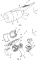
- FIGS. 1-3 illustrate a propulsion system 10 for an aircraft.
- the propulsion system 10 of FIGS. 1-3 includes a gas turbine engine 20, a nacelle 22, and a controller 24.
- the gas turbine engine 20 of FIGS. 1-3 is configured as a multi-spool turbofan gas turbine engine for the aircraft propulsion system 10.
- gas turbine engine propulsion systems e.g., those including a turboshaft gas turbine engine, a turboprop gas turbine engine, a turbojet gas turbine engine, a propfan gas turbine engine, an open rotor gas turbine engine, etc.
- gas turbine engines e.g., an electric-fan propulsion system, an electric-prop propulsion system, etc.
- FIG. 3 illustrates a cutaway, side view of the propulsion system 10.
- the gas turbine engine 20 of FIG. 3 includes a fan section 26, a compressor section 28, a combustor section 30, a turbine section 32, and an engine static structure 34.
- the gas turbine engine 20 sections 26, 28, 30, and 32, of FIG. 3 are arranged sequentially along an axial centerline 36 (e.g., a rotational axis) of the gas turbine engine 20.
- the compressor section 28 may include a low-pressure compressor (LPC) section 28A and a high-pressure compressor (HPC) section 28B.
- the turbine section 32 may include a high-pressure turbine (HPT) section 32A and a low-pressure turbine (LPT) section 32B.
- LPC low-pressure compressor
- HPC high-pressure compressor
- LPT high-pressure turbine
- LPT low-pressure turbine
- Each of the gas turbine engine 20 sections 26, 28A, 28B, 32A, and 32B includes a bladed rotor 38, 40, 42, 44, 46.
- the fan rotor 38 and the LPC rotor 40 are connected to and driven by the LPT rotor 46 through a shaft 48.
- the HPC rotor 42 is connected to and driven by the HPT rotor 44 through a shaft 50.
- the shaft 48 and the shaft 50 are concentrically disposed relative to the axial centerline 36 and configured for rotation about the axial centerline 36 relative to the engine static structure 34.
- the fan rotor 38 draws and directs ambient air into the propulsion system 10.
- the air may be divided into a core flow path 52 and a bypass flow path 54.
- the core flow path 52 extends axially along the axial centerline 36 within the gas turbine engine 20 and through the compressor section 28, the combustor section 30, and the turbine section 32.
- the core air is compressed by the LPC rotor 40 and the HPC rotor 42 and directed into a combustion chamber of a combustor (e.g., an annular combustor) in the combustor section 30.
- Fuel is injected into the combustion chamber through one or more fuel injectors and mixed with the compressed core air to provide a fuel-air mixture.
- This fuel-air mixture is ignited and combustion products thereof flow through and sequentially cause the HPT rotor 44 and the LPT rotor 46 to rotate.
- the rotation of the HPT rotor 44 and the LPT rotor 46 respectively drive rotation of the HPC rotor 42 and the LPC rotor 40.
- the rotation of the LPT rotor 46 also drives rotation of the fan rotor 38.
- the bypass flow path 54 extends axially along the axial centerline 36 and between the gas turbine engine 20 and the nacelle 22.
- the nacelle 22 is configured to house and provide an aerodynamic cover for the gas turbine engine 20.
- the nacelle 22 extends axially along the axial centerline 36 between and to an upstream end 56 (e.g., an axially forward end) of the nacelle 22 and a downstream end 58 (e.g., an axially aft end) of the nacelle 22.
- the nacelle 22 extends circumferentially about (e.g., completely around) the axial centerline 36.
- the nacelle 22 may include or otherwise be mounted to a pylon 60 (e.g., an engine mount structure) configured to mount the nacelle 22, and thereby the propulsion system 10, to an aircraft wing or fuselage.
- the air inlet section 62 is disposed at (e.g., on, adjacent, or proximate) the upstream end 56.
- the fan cowl section 64 is disposed between (e.g., axially between) the air inlet section 62 and the thrust reverser section 66.
- the thrust reverser section 66 is disposed at (e.g., on, adjacent, or proximate) the downstream end 58.
- the fan cowl section 64 is configured to generally surround the fan rotor 38.
- the fan cowl 64 of FIGS. 1 and 2 includes a first cowl door 68 and a second cowl door 70.
- Each of the first cowl door 68 and the second door 70 may be hingedly coupled to the pylon 60 or to a fixed portion of the nacelle 22 (e.g., the fan cowl section 64) to facilitate access to internal components of the propulsion system 10 and its gas turbine engine 20.
- Each of the first cowl door 68 and the second cowl door 70 is pivotable between an open position and a closed position.
- first cowl door 68 and the second cowl door 70 form a substantially continuous exterior surface of the fan cowl section 64 (e.g., the first cowl door 68 and the second cowl door 70 are positioned for flight).
- the first cowl door 68 and the second cowl door 70 may be selectively latched together in the closed position by one or more latch assemblies, as will be discussed in further detail.
- the first cowl door 68 and the second cowl door 70 may be in a position other than the closed position (e.g., a partially open position or a fully open position).
- the thrust reverser section 66 may include a first half 72 (e.g., a left half) and a second half 74 (e.g., a right half). All or portions of the first half 72 and the second half 74 may be movable (e.g., axially translatable, rotatable, etc.) to redirect gas flow along the bypass flow path and/or the core flow path to provide deceleration (e.g., reverse thrust) for an aircraft on which the propulsion system 10 is mounted.
- the thrust reverser section 66 of FIG. 2 includes a translating sleeve 76 forming a portion of an exterior of the thrust reverser section 66.
- the translating sleeve 66 is axially translatable along the axial centerline 36 between a stowed position (e.g., an axially forward position) and a deployed position (e.g., an axially aft position).
- a stowed position e.g., an axially forward position
- a deployed position e.g., an axially aft position
- the translating sleeve 66 covers one or more cascade arrays 78 of the thrust reverser section 66.
- the translating sleeve 66 uncovers the cascade arrays 78.
- air from the gas turbine engine 20 e.g., air flow along the bypass flow path 54
- the cascade arrays 78 in a forward direction to generate reverse thrust for the propulsion system 10.
- the controller 24 includes a processor 110 connected in signal communication with memory 112.
- the processor 110 may include any type of computing device, computational circuit, processor(s), CPU, computer, or the like capable of executing a series of instructions that are stored in the memory 112. Instructions can be directly executable or can be used to develop executable instructions. For example, instructions can be realized as executable or non-executable machine code or as instructions in a high-level language that can be compiled to produce executable or non-executable machine code. Further, instructions also can be realized as or can include data. Computer-executable instructions also can be organized in any format, including routines, subroutines, programs, data structures, objects, modules, applications, applets, functions, etc.
- the instructions may include an operating system, and/or executable software modules such as program files, system data, buffers, drivers, utilities, and the like.
- the executable instructions may apply to any functionality described herein to enable the controller 24 to accomplish the same algorithmically and/or by coordination of propulsion system 10 components.
- the memory 112 may include a single memory device or a plurality of memory devices; e.g., a computer-readable storage device that can be read, written, or otherwise accessed by a general purpose or special purpose computing device, including any processing electronics and/or processing circuitry capable of executing instructions.
- the present disclosure is not limited to any particular type of memory device, which may be non-transitory, and may include read-only memory, random access memory, volatile memory, non-volatile memory, static memory, dynamic memory, flash memory, cache memory, volatile or non-volatile semiconductor memory, optical disk storage, magnetic disk storage, magnetic tape, other magnetic storage devices, or any other medium capable of storing one or more instructions, and/or any device that stores digital information.
- the memory device(s) may be directly or indirectly coupled to the controller 24.
- the controller 24 may include, or may be in communication with, an input device that enables a user to enter data and/or instructions, and may include, or be in communication with, an output device configured, for example to display information (e.g., a visual display or a printer), or to transfer data, etc. Communications between the controller 24 and other electrical and/or electronic components (e.g., other processing and/or control systems, sensors, etc.) may be via a hardwire connection or via a wireless connection.
- portions of the controller 24 may assume various forms (e.g., digital signal processor, analog device, etc.) capable of performing the functions described herein.
- the controller 24 may form or otherwise be part of an electronic engine controller (EEC) for the gas turbine engine 20.
- EEC electronic engine controller
- the EEC may control operating parameters of the gas turbine engine 20 including, but not limited to, fuel flow, stator vane position (e.g., variable compressor inlet guide vane (IGV) position), compressor air bleed valve position, shaft (e.g., shaft 48 and/or shaft 50 torque and/or rotation speed, etc. so as to control an engine power or performance of the gas turbine engine 20.
- the EEC may modulate fuel flow to the combustor of the combustor section 30 to obtain a desired output power of the gas turbine engine 20.
- the controller 24 may be connected in signal communication with or otherwise configured to receive a signal from one or more sensors 114 to measure or otherwise determine an engine output parameter of the gas turbine engine 20 such as, but not limited to, shaft 48 rotation speed (N1), shaft 50 rotation speed (N2), air inlet temperature corrected shaft 48 rotation speed and/or shaft 50 rotation speed (N1C, N2C), shaft 48 torque, shaft 50 torque, shaft 48 shaft horsepower (SHP), shaft 50 SHP, an interstage turbine temperature (ITT), and combustor fuel flow rate.
- the EEC may be part of a full authority digital engine control (FADEC) system for the gas turbine engine 20.
- the controller 24 may be connected in signal communication with one or more electronic control systems of an aircraft on which the propulsion system 10 is mounted.
- FIG. 4 illustrates a block diagram for a loss of load path detection (LLPD) system 116.
- the LLPD system 116 may include the controller 24 (e.g., the controller 24 may be a dedicated component of the LLPD system 116). Alternatively, the LLPD system 116 may be connected in signal communication with the controller 24, which controller 24 may execute, monitor, or control one or more other propulsion system 10 functions.
- the LLPD system 116 may operate to identify a presence or an absence of a failure in one or more structural load paths of the nacelle 22. In particular, the LLPD system 116 may identify latent structural load path failures for the nacelle 22. Conventional practices for identifying structural load path failures involve periodic visual inspections by aircraft maintenance personnel.
- latent structural load path failures may be difficult or impossible to identify using conventional visual inspection practices or using conventional latch position systems for identifying a latch or unlatched condition of a latch assembly.
- latent structural load path failures include, but are not limited to, actuator rod end failures leading to disconnect, thrust reverser locking element failures, thrust reverser primary lock hook failure, or other failure upstream of latch closure indications, or a hook locking element failure.
- the LLPD system 116 of FIG. 4 includes one or more load cells 118 disposed on the nacelle 22.
- the load cells 118 may be installed in structural load paths of the nacelle 22 to identify a failure of one or more of the structural load paths.
- the load cells 118 are configured to convert a force (e.g., a tension, a compression, a pressure, or a torque) into an electrical signal.
- the load cells 118 may have a strain gauge or other force transducer configuration.
- the load cells 118 may be incorporated into or otherwise formed by attachment hardware (e.g., mechanical fasteners, insert fittings, mounting brackets or other structures, locking bodies, etc.) or other structural load path components of the nacelle 22.
- attachment hardware e.g., mechanical fasteners, insert fittings, mounting brackets or other structures, locking bodies, etc.
- the present disclosure is not limited to any particular configuration of the load cells 118.
- the load cells 118 are connected in signal communication with the controller 24 to provide
- FIG. 5 illustrates a first example of an application of the LLPD system 116 and the load cells 118 on a portion of the nacelle 22.
- FIG. 5 illustrates a cutaway, side view of one of a latch assembly 86 for the first cowl door 68 and the second cowl door 70 (see FIG. 2 ).
- the latch assembly 86 of FIG. 5 includes a first latch assembly portion 88 and a second latch assembly portion 90.
- the first latch assembly portion 88 and the second latch assembly portion 90 are shown in FIG. 5 in an engaged condition.
- the first latch assembly portion 88 includes a housing 92, a handle 94, a latch 96, and a pin 98.
- the housing 92 is fixedly mounted to the first cowl door 68.
- the handle 94 is pivotably mounted to the housing 92 at a first pivot location 100.
- the latch 96 is pivotably mounted to the handle 94 at a second pivot location 102 by the pin 98 (e.g., a cylindrical body).
- the latch 96 includes a latch hook 106.
- the second latch assembly portion 90 includes a keeper 108.
- the latch 96 is pivotable about the pin 98, by operation of the handle 94, to selectively engage the hook 106 with the keeper 108 or to selectively disengage the hook 106 from the keeper 108.
- the load cell 118 of FIG. 5 is disposed on or embedded within the pin 98 to measure loading experienced by the latch assembly 86 while holding the first cowl door 68 and the second cowl door 70 together in their respective closed positions. Additional details of the incorporation of a load cell with a latch assembly may be found, for example, in U.S. Patent Publication NO. 2009/0173823 , the disclosure of which is hereby incorporated herein by reference in
- FIG. 6 illustrates a second example of an application of the LLPD system 116 and the load cells 118 on a portion of the nacelle 22.
- FIG. 6 illustrates a cutaway, side view of a portion of the thrust reverser section 66 including the translating sleeve 76 and a locking actuator assembly 120.
- the locking actuator assembly 120 includes a locking actuator 122 and an actuator mounting body 124.
- the locking actuator 122 is configured to selectively engage the translating sleeve 76. With the translating sleeve 76 in the stowed position (e.g., an axially forward position), the locking actuator 122 engages the translating sleeve 76 to lock the translating sleeve in the stowed position.
- the locking actuator 122 disengages the translating sleeve 76 to allow the translating sleeve 76 to translate to the deployed position.
- the actuator mounting body 124 fixedly mounts the locking actuator 122 to a fixed structure 126 of the thrust reverser section 66.
- the actuator mounting body 124 may be configured as a bracket or other attachment hardware for fixedly mounting the locking actuator 122.
- the fixed structure 126 may include or otherwise be formed by a torque box, a casing, or another fixed structure of the thrust reverser section 66 positioned axially adjacent the translating sleeve 76.
- the load cell 118 of FIG. 6 is disposed on or embedded within the actuator mounting body 124 to measure loading experienced by the locking actuator assembly 120 while retaining the translating sleeve 76 in the stowed position.
- FIG. 7 illustrates a third example of an application of the LLPD system 116 and the load cells 118 on a portion of the nacelle 22.
- the LLPD system 116 of FIG. 7 may be configured for use with a clamshell-type (or bucket-type) thrust reverser assembly, however, the LLPD system 116 of FIG. 7 is not limited to use with the foregoing exemplary thrust reverser assemblies.
- FIG. 7 illustrates a cutaway view of a portion of a locking assembly 128 (e.g., a primary lock) for a thrust reverser.
- the 7 includes an S-hook lock 130 configured to selectively engage a first thrust reverser door 132 and a second thrust reverser door 134 to lock the first thrust reverser door 132 and the second thrust reverser door 134 together in their respective stowed positions.
- the S-hook lock 130 is rotatable about a rotational axis 136 to engage or disengage the first thrust reverser door 132 and the second thrust reverser door 134.
- the load cell 118 of FIG. 7 is disposed on or embedded within the S-hook lock 130 to measure loading experienced by the S-hook lock 130 while retaining the first thrust reverser door 132 and the second thrust reverser door 134 in their respective the stowed positions.
- FIG. 7 includes two of the load cells 118, however, the present disclosure is not limited to the particular configuration of FIG. 7 . Additional details of the thrust reverser locking assemblies including S-hooks may be found, for example, in U.S. Patent Publication NO. 2020/0063474 , the disclosure of which is hereby incorporated herein by reference in its entirety.
- the controller 24 may include instructions which, when executed by the controller 24 (e.g., the processor 110) cause the controller 24 (e.g., the processor 110) to control one or more aspects of the LLPD system 116 operation.
- the controller 24 may determine or otherwise receive an engine output parameter of the gas turbine engine 20.
- the controller 24 may compare the engine output parameter to a threshold engine output parameter value (e.g., a predetermine value). For example, the controller 24 may compare shaft 48 rotation speed (e.g., N1, N1C) to the threshold engine output parameter to identify whether the shaft 48 rotation speed is greater than or less than the threshold engine output parameter.
- a threshold engine output parameter value e.g., a predetermine value
- the threshold engine output parameter may be selected to correspond to a relatively high-power output of the gas turbine engine 20 such as may be present during a takeoff condition for the propulsion system 10, where nacelle 22 structural load path loading is expected to be relatively high.
- the threshold engine output parameter may be greater than or equal to 50 percent of the rated engine output parameter (e.g., shaft 48 rotation speed (N1, N1C)) for the gas turbine engine 20 or, in some cases, greater than or equal to 75 percent of the rated engine output parameter (e.g., shaft 48 rotation speed (N1, N1C)) for the gas turbine engine 20.
- the use of a threshold engine output parameter corresponding to a relatively high-power output of the gas turbine engine 20 facilitates sufficiently high structural loading at the structural load paths monitored by the LLPD system 116 relative to the zero-load structural loading at these respective structural load paths.
- the controller 24 may compare a measured loading (e.g., a structural loading signal) for each of the load cells 118 at their respective structural load path positions to a zero-load value for each of the respective load cells 118 and their structural load path positions.
- the zero-load value for each of the load cells 118 may be a predetermined value stored in memory 112.
- the predetermined zero-load value may be measured or otherwise determined for each of the structural load paths and respective load cells 118 through routine experimentation or other analysis.
- the controller 24 may determine (e.g., dynamically determine) the zero-load value for each of the structural load paths and respective load cells 118.
- the controller 24 may measure the loading at the structural load paths using the respective load cell 118 loading measurements during a low-power condition of the propulsion system 10 (e.g., ground idle, ground taxiing, minimum cruise during flight, etc.). With the engine output parameter greater than the threshold engine output parameter, the structural loading for each of the load cells 118 may be expected to be significantly greater than the zero-load value for each of the respective load cells 118. The controller 24 may identify an absence of a structural load path failure for the structural load path associated with each of the load cells 118 when the structural loading measured by each of the load cells 118 is greater than the zero-load value for each of the respective load cells 118.
- a low-power condition of the propulsion system 10 e.g., ground idle, ground taxiing, minimum cruise during flight, etc.
- the controller 24 may identify a presence of a structural load path failure for the structural load path associated with each of the load cells 118 when the structural loading measured by each of the load cells 118 is less than the zero-load value for each of the respective load cells 118.
- the controller 24 may generate a warning (e.g., a warning light, a warning message, an audible alarm, etc.) for a pilot or other operator of the propulsion system 10 or its associated aircraft, identifying the presence of the structural load path failure.
- a warning e.g., a warning light, a warning message, an audible alarm, etc.
- the present disclosure LLPD system 116 facilitates identification of latent nacelle structural load path failures during a flight condition of the propulsion system 10. Identification of the presence or absence of a structural load path failure during high-power gas turbine engine 20 operating conditions (e.g., during takeoff or other conditions in which the engine output parameter exceeds the threshold engine output parameter) provides structural load path loading conditions which are expected to greatly exceed zero-load values for the structural load paths during normal conditions, and significantly decreases the likelihood of a false positive identification of structural load path failure. As a result, time-consuming visual inspections of nacelle structural load paths may be eliminated or reduced, thereby improving aircraft operational time. By providing improved identification of latent structural load path failures, the LLPD system 116 may further facilitate the use of smaller and/or lighter weight nacelle components which will not need to be sized or otherwise selected for resistance to residual fatigue, thereby reducing nacelle weight.
- any one of these structures may describe the operations as a sequential process, many of the operations can be performed in parallel or concurrently.
- the order of the operations may be rearranged.
- a process may correspond to a method, a function, a procedure, a subroutine, a subprogram, etc.
Landscapes
- Engineering & Computer Science (AREA)
- Aviation & Aerospace Engineering (AREA)
- Control Of Turbines (AREA)
Applications Claiming Priority (1)
| Application Number | Priority Date | Filing Date | Title |
|---|---|---|---|
| US202363531121P | 2023-08-07 | 2023-08-07 |
Publications (1)
| Publication Number | Publication Date |
|---|---|
| EP4506242A1 true EP4506242A1 (de) | 2025-02-12 |
Family
ID=92263953
Family Applications (1)
| Application Number | Title | Priority Date | Filing Date |
|---|---|---|---|
| EP24193447.0A Pending EP4506242A1 (de) | 2023-08-07 | 2024-08-07 | System zur erkennung des lastverlustwegs für eine flugzeugantriebssystemgondel und verfahren zur verwendung davon |
Country Status (2)
| Country | Link |
|---|---|
| US (1) | US20250051021A1 (de) |
| EP (1) | EP4506242A1 (de) |
Citations (5)
| Publication number | Priority date | Publication date | Assignee | Title |
|---|---|---|---|---|
| US20090173823A1 (en) | 2008-01-07 | 2009-07-09 | Rohr, Inc. | Method and component for determining load on a latch assembly |
| US20170369188A1 (en) * | 2016-06-23 | 2017-12-28 | General Electric Company | Wireless aircraft engine monitoring system |
| US20200063474A1 (en) | 2018-08-21 | 2020-02-27 | Goodrich Actuation Systems Limited | Locking mechanism |
| US10676215B2 (en) * | 2017-03-22 | 2020-06-09 | Safran Aero Boosters Sa | Turbomachine cowling with screen |
| EP3907139A1 (de) * | 2020-05-05 | 2021-11-10 | Rohr, Inc. | Systeme und verfahren zur längenanpassung eines verriegelungshakens |
Family Cites Families (1)
| Publication number | Priority date | Publication date | Assignee | Title |
|---|---|---|---|---|
| FR3087515B1 (fr) * | 2018-10-22 | 2021-01-29 | Airbus Operations Sas | Glissiere a frottement sec a surfaces de contact inclinees |
-
2024
- 2024-08-07 EP EP24193447.0A patent/EP4506242A1/de active Pending
- 2024-08-07 US US18/797,093 patent/US20250051021A1/en active Pending
Patent Citations (5)
| Publication number | Priority date | Publication date | Assignee | Title |
|---|---|---|---|---|
| US20090173823A1 (en) | 2008-01-07 | 2009-07-09 | Rohr, Inc. | Method and component for determining load on a latch assembly |
| US20170369188A1 (en) * | 2016-06-23 | 2017-12-28 | General Electric Company | Wireless aircraft engine monitoring system |
| US10676215B2 (en) * | 2017-03-22 | 2020-06-09 | Safran Aero Boosters Sa | Turbomachine cowling with screen |
| US20200063474A1 (en) | 2018-08-21 | 2020-02-27 | Goodrich Actuation Systems Limited | Locking mechanism |
| EP3907139A1 (de) * | 2020-05-05 | 2021-11-10 | Rohr, Inc. | Systeme und verfahren zur längenanpassung eines verriegelungshakens |
Also Published As
| Publication number | Publication date |
|---|---|
| US20250051021A1 (en) | 2025-02-13 |
Similar Documents
| Publication | Publication Date | Title |
|---|---|---|
| EP2904242B1 (de) | Modellbasierte motoreinlasszustandsschätzung | |
| US12379645B2 (en) | Propulsor blade imaging assembly for an aircraft propulsion system | |
| US12410727B2 (en) | Propulsor blade imaging assembly method for an aircraft propulsion system | |
| CA3254644A1 (en) | Hydrogen leak detection system for an aircraft propulsion system | |
| EP4345258A1 (de) | Systeme und verfahren zur bestimmung von gasturbinenmotortemperaturen | |
| US20250051021A1 (en) | Loss of load path detection system for aircraft propulsion system nacelle and method for using same | |
| EP4461650A1 (de) | System und verfahren zur erkennung der blockierung eines lufteinlasses für ein flugzeugantriebssystem | |
| EP4397845A1 (de) | Enteisungssystem und verfahren für ein flugzeugantriebssystem | |
| US20240060426A1 (en) | Systems and methods for determining gas turbine engine operating margins | |
| US20250101877A1 (en) | System and method for identifying rubbing conditions for engine rotational equipment | |
| US20240217666A1 (en) | Latch assembly for an aircraft propulsion system cowl | |
| US12535016B2 (en) | Systems and methods for identifying insufficient starter acceleration for an aircraft engine | |
| US12392255B2 (en) | Systems and methods for determining gas turbine engine operating margins | |
| US12560280B2 (en) | Engine oil system for an aircraft propulsion system and method for controlling same | |
| US20240067350A1 (en) | Engine control system and method with artificial intelligence sensor training | |
| US20260109471A1 (en) | Electrical lockout system for aircraft propulsion system | |
| US20240092496A1 (en) | Exhaust nozzle assembly for an aircraft propulsion system | |
| CA3253230A1 (en) | Method and apparatus for automated gas turbine engine testing | |
| Hampton et al. | Design for durability-The F101-GE-100 engine | |
| Scheidler et al. | Mapping the Control Parameters of an Analog Fuel Control to Prepare for the Retrofit of a Digital Control Unit | |
| Labendik et al. | BYPASS TURBOJET OPERATING PERFORMANCE SIMULATION BASED ON SIMILARITY PRINCIPLES |
Legal Events
| Date | Code | Title | Description |
|---|---|---|---|
| PUAI | Public reference made under article 153(3) epc to a published international application that has entered the european phase |
Free format text: ORIGINAL CODE: 0009012 |
|
| STAA | Information on the status of an ep patent application or granted ep patent |
Free format text: STATUS: THE APPLICATION HAS BEEN PUBLISHED |
|
| AK | Designated contracting states |
Kind code of ref document: A1 Designated state(s): AL AT BE BG CH CY CZ DE DK EE ES FI FR GB GR HR HU IE IS IT LI LT LU LV MC ME MK MT NL NO PL PT RO RS SE SI SK SM TR |
|
| STAA | Information on the status of an ep patent application or granted ep patent |
Free format text: STATUS: REQUEST FOR EXAMINATION WAS MADE |
|
| 17P | Request for examination filed |
Effective date: 20250812 |
|
| GRAP | Despatch of communication of intention to grant a patent |
Free format text: ORIGINAL CODE: EPIDOSNIGR1 |
|
| STAA | Information on the status of an ep patent application or granted ep patent |
Free format text: STATUS: GRANT OF PATENT IS INTENDED |