EP3263261A1 - Roue dentée, procédé de fabrication de denture d'une roue dentée et outil destiné à fabriquer la denture d'une roue dentée - Google Patents
Roue dentée, procédé de fabrication de denture d'une roue dentée et outil destiné à fabriquer la denture d'une roue dentée Download PDFInfo
- Publication number
- EP3263261A1 EP3263261A1 EP17177950.7A EP17177950A EP3263261A1 EP 3263261 A1 EP3263261 A1 EP 3263261A1 EP 17177950 A EP17177950 A EP 17177950A EP 3263261 A1 EP3263261 A1 EP 3263261A1
- Authority
- EP
- European Patent Office
- Prior art keywords
- gear
- toothing
- teeth
- tool
- produced
- Prior art date
- Legal status (The legal status is an assumption and is not a legal conclusion. Google has not performed a legal analysis and makes no representation as to the accuracy of the status listed.)
- Withdrawn
Links
- 238000004519 manufacturing process Methods 0.000 title claims abstract description 18
- 238000000034 method Methods 0.000 claims abstract description 39
- 230000000295 complement effect Effects 0.000 claims abstract description 12
- 239000000463 material Substances 0.000 claims abstract description 12
- 230000008569 process Effects 0.000 claims abstract description 10
- 230000005540 biological transmission Effects 0.000 claims description 27
- 238000000227 grinding Methods 0.000 claims description 24
- 238000005520 cutting process Methods 0.000 claims description 10
- 230000007704 transition Effects 0.000 claims description 2
- 239000011295 pitch Substances 0.000 description 36
- 230000008901 benefit Effects 0.000 description 7
- 238000003754 machining Methods 0.000 description 6
- 230000009467 reduction Effects 0.000 description 6
- 238000005516 engineering process Methods 0.000 description 4
- 230000003628 erosive effect Effects 0.000 description 2
- 230000008859 change Effects 0.000 description 1
- 238000002485 combustion reaction Methods 0.000 description 1
- 238000010924 continuous production Methods 0.000 description 1
- 230000018109 developmental process Effects 0.000 description 1
- RDYMFSUJUZBWLH-UHFFFAOYSA-N endosulfan Chemical compound C12COS(=O)OCC2C2(Cl)C(Cl)=C(Cl)C1(Cl)C2(Cl)Cl RDYMFSUJUZBWLH-UHFFFAOYSA-N 0.000 description 1
- 230000005284 excitation Effects 0.000 description 1
- 230000010355 oscillation Effects 0.000 description 1
- 230000008092 positive effect Effects 0.000 description 1
- 238000003672 processing method Methods 0.000 description 1
- 238000005096 rolling process Methods 0.000 description 1
- 238000005549 size reduction Methods 0.000 description 1
- 230000001360 synchronised effect Effects 0.000 description 1
- 230000002123 temporal effect Effects 0.000 description 1
- 230000036346 tooth eruption Effects 0.000 description 1
Images

Classifications
-
- B—PERFORMING OPERATIONS; TRANSPORTING
- B23—MACHINE TOOLS; METAL-WORKING NOT OTHERWISE PROVIDED FOR
- B23F—MAKING GEARS OR TOOTHED RACKS
- B23F5/00—Making straight gear teeth involving moving a tool relatively to a workpiece with a rolling-off or an enveloping motion with respect to the gear teeth to be made
- B23F5/12—Making straight gear teeth involving moving a tool relatively to a workpiece with a rolling-off or an enveloping motion with respect to the gear teeth to be made by planing or slotting
- B23F5/16—Making straight gear teeth involving moving a tool relatively to a workpiece with a rolling-off or an enveloping motion with respect to the gear teeth to be made by planing or slotting the tool having a shape similar to that of a spur wheel or part thereof
- B23F5/163—Making straight gear teeth involving moving a tool relatively to a workpiece with a rolling-off or an enveloping motion with respect to the gear teeth to be made by planing or slotting the tool having a shape similar to that of a spur wheel or part thereof the tool and workpiece being in crossed axis arrangement, e.g. skiving, i.e. "Waelzschaelen"
-
- B—PERFORMING OPERATIONS; TRANSPORTING
- B23—MACHINE TOOLS; METAL-WORKING NOT OTHERWISE PROVIDED FOR
- B23F—MAKING GEARS OR TOOTHED RACKS
- B23F17/00—Special methods or machines for making gear teeth, not covered by the preceding groups
- B23F17/006—Special methods or machines for making gear teeth, not covered by the preceding groups using different machines or machining operations
-
- B—PERFORMING OPERATIONS; TRANSPORTING
- B23—MACHINE TOOLS; METAL-WORKING NOT OTHERWISE PROVIDED FOR
- B23F—MAKING GEARS OR TOOTHED RACKS
- B23F21/00—Tools specially adapted for use in machines for manufacturing gear teeth
- B23F21/04—Planing or slotting tools
- B23F21/10—Gear-shaper cutters having a shape similar to a spur wheel or part thereof
-
- B—PERFORMING OPERATIONS; TRANSPORTING
- B23—MACHINE TOOLS; METAL-WORKING NOT OTHERWISE PROVIDED FOR
- B23F—MAKING GEARS OR TOOTHED RACKS
- B23F23/00—Accessories or equipment combined with or arranged in, or specially designed to form part of, gear-cutting machines
- B23F23/003—Generating mechanisms
-
- B—PERFORMING OPERATIONS; TRANSPORTING
- B23—MACHINE TOOLS; METAL-WORKING NOT OTHERWISE PROVIDED FOR
- B23F—MAKING GEARS OR TOOTHED RACKS
- B23F5/00—Making straight gear teeth involving moving a tool relatively to a workpiece with a rolling-off or an enveloping motion with respect to the gear teeth to be made
- B23F5/02—Making straight gear teeth involving moving a tool relatively to a workpiece with a rolling-off or an enveloping motion with respect to the gear teeth to be made by grinding
-
- B—PERFORMING OPERATIONS; TRANSPORTING
- B23—MACHINE TOOLS; METAL-WORKING NOT OTHERWISE PROVIDED FOR
- B23Q—DETAILS, COMPONENTS, OR ACCESSORIES FOR MACHINE TOOLS, e.g. ARRANGEMENTS FOR COPYING OR CONTROLLING; MACHINE TOOLS IN GENERAL CHARACTERISED BY THE CONSTRUCTION OF PARTICULAR DETAILS OR COMPONENTS; COMBINATIONS OR ASSOCIATIONS OF METAL-WORKING MACHINES, NOT DIRECTED TO A PARTICULAR RESULT
- B23Q27/00—Geometrical mechanisms for the production of work of particular shapes, not fully provided for in another subclass
- B23Q27/006—Geometrical mechanisms for the production of work of particular shapes, not fully provided for in another subclass by rolling without slippage two bodies of particular shape relative to each other
-
- F—MECHANICAL ENGINEERING; LIGHTING; HEATING; WEAPONS; BLASTING
- F16—ENGINEERING ELEMENTS AND UNITS; GENERAL MEASURES FOR PRODUCING AND MAINTAINING EFFECTIVE FUNCTIONING OF MACHINES OR INSTALLATIONS; THERMAL INSULATION IN GENERAL
- F16H—GEARING
- F16H49/00—Other gearings
- F16H49/001—Wave gearings, e.g. harmonic drive transmissions
Definitions
- the invention relates to a method for producing a toothing, which has a module which is smaller than 0.5 mm or which is smaller than 0.25 mm or which is smaller than 0.15 mm, and the x teeth and a gear pitch p comprising a gear of a gear blank which rotates about a first axis of rotation, material is removed by means of a tool gear which rotates in synchronism with the gear blank about a second axis of rotation and which has a counter toothing complementary to the toothing to be produced.
- the invention also relates to a gear made with such a method or with such a tool.
- the invention further relates to a voltage wave transmission with such a gear, as well as a vehicle with such a voltage wave transmission and a robot with such a stress wave transmission.
- a stress wave transmission usually has a rigid, circular internal gear (Circularspline) and a flexible external gear (Flexspline), which is arranged in the interior of the rigid internal gear.
- an elliptical wave generator is rotatably arranged by means of a rolling bearing deforming the flexible externally toothed gear to a generally elliptical shape to engage the gears of the internal gear and the flexible externally toothed gear at each end of the ellipse main axis.
- the teeth of the flexible external gear arrive at opposite sides circumferentially in and out of engagement with the teeth of the rigid internally toothed gear, wherein the teeth of the externally toothed gear continuously move radially by at least their tooth height.
- the reduction ratio is a function of the number of teeth and that the greater the reduction ratio can be achieved, the more teeth can be arranged on the pitch circles of the external gear and the internal gear.
- gears with a smaller gear pitch must be made to achieve a higher reduction ratio, if the pitch diameter is to remain unchanged.
- the production of gears, in particular of gears for stress wave transmission, whose teeth have a small gear pitch technically very complex.
- gears especially internal or external gears.
- skiving is one of several known methods of manufacturing gears.
- the toothing to be produced on a workpiece is made with a tool gear has generated, the cutting edges and a toothing complementary to the toothing produced.
- the workpiece and the gear are positioned on mutually skew Rotationsaxen and, in particular with the same direction of rotation, synchronously rotated.
- the cutting edges of the tool gear here due to the skewed position of the workpiece and gear in the workpiece from a movement that is similar to the movement of an excavator bucket, whereby the toothing is made by machining.
- the rotary tool gear is moved relative to the workpiece in an axial feed direction with respect to the rotating workpiece in order to produce the toothing over the desired width by means of the cutting movements described above.
- the manufacturability of small-sized tools has hitherto been limited in terms of manufacturing technology.
- a device for gear cutting of gears by skiving has a rotatably driven workpiece spindle for receiving the gear wheel, which is to be toothed in particular, and a tool spindle which can be driven in rotation and which carries a peeling wheel having cutting teeth.
- the distance of at least some equalized teeth of the Schölrades corresponds to a multiple of the regular pitch of a regular Schölrades, wherein the peeling wheel has an odd number of teeth when the number of teeth of the workpiece to be toothed is straight and vice versa.
- the object is achieved by a method of the aforementioned type, which is characterized in that adjacent teeth of the counter teeth on the pitch circle are each spaced by n * p (n multiplied by p), where n is a natural number greater than 1 and wherein x and n are prime.
- x indicates the total number of teeth of the toothing of the gear to be produced.
- a tool gear which is characterized in that the tool gear has a toothing to be produced, which has a module which is smaller than 0.5 mm or which is smaller than 0.25 mm or smaller than 0, Is 15 mm and having x teeth and a gear pitch p, complementary complementary teeth, wherein adjacent teeth of the counter teeth on the pitch circle each by n * p (n multiplied by p) are spaced apart, where n is a natural number greater than 1 and wherein x and n are prime.
- a voltage wave transmission which includes at least one gear produced by the method according to the invention and / or with the tool according to the invention.
- the required tool gears can be made simply by using rotating grinding wheels, because the grinding wheels - even with a very small modulus counter teeth of the tool gear - itself may have a sufficient thickness to be stable in itself. Therefore, no complex procedures, such as erosion and other processing methods must be used to produce small-sized tool gears in the required quality, but this for the implementation of the Invention, in particular for carrying out the method according to the invention, not excluded, but quite possible alternatively.
- the production of the counter-toothing of the tool gear wheel by profiling by means of a rotating grinding wheel can in particular be carried out in such a way that by means of the rotating grinding wheel successively the clearances between the adjacent and on the pitch circle in each case by n ⁇ p (n multiplied by p) spaced apart teeth of the tool gear be generated by abrasive erosion.
- the axis of rotation of the grinding wheel is preferably aligned tangentially to the tool gear to be produced and / or arranged in a direction perpendicular to the axis of symmetry of the tool gear to be produced plane.
- first tooth gaps of the teeth are at least partially produced and / or processed at first during the first revolution, which are spaced apart from each other along the pitch circle by more than one gear pitch p.
- adjacent teeth of the counter-toothing on the pitch circle are each spaced apart by np (n multiplied by p), where n is a natural number greater than one.
- n * p it may be advantageously provided that the radial center lines of adjacent first tooth spaces of the toothing to be produced on the pitch circle are each spaced apart from one another by n * p.
- first tooth spaces it is not necessary for the first tooth spaces to be completely produced already during the first revolution of the gear blank. Rather, it can advantageously be provided that, for a further n-1 revolutions, other tooth gaps of the teeth are first of all machined and then, at the nth rotation, the processing of the first tooth spaces is continued, and so on.
- the rotation of the gear blank and the synchronous rotation of the tool gear are preferably not interrupted here. Because of the condition that the number of teeth x of the teeth to be produced and n are prime, it is advantageously achieved that, after every n revolutions of the gear blank, all the tooth gaps to be worked out have been reached by the teeth of the tool gear. This in particular, without stopping the rotation of the gear blank and the tool gear and to change the relative rotational position of the gear blank to the tool gear while stopped rotation.
- all tooth gaps of the toothing are preferably produced in a single continuous process without re-clamping the tool and / or gear blank, all the directly adjacent tooth gaps and all directly adjacent teeth result in the same distance from one another along the pitch circle.
- the inventive method makes it easier to form the tool gear, so that it can be made in particular less expensive. This is because the counter teeth of the tool gear have teeth spaced much farther apart than a tool gear commonly used in, for example, skiving.
- a tool gear is used in which adjacent teeth along the pitch circle have the same distance from each other, as the teeth of the toothing to be produced.
- the tool gear according to the invention complementary to the toothing to be produced symbols symbols having along the pitch circle n-fold greater distance from each other.
- x and n are prime if there is no natural number other than one sharing both x and n.
- n the smallest number is selected from the set of all numbers divisive with x.
- a natural number less than 8 is selected for n, which is a prime alien to x.
- n 2, 3, 4, 5 or 7.
- the invention can for example be realized in such a way that the gear to be produced by skiving - but with a tool according to the invention - gear wheel is produced.
- the toothing is produced by skiving, wherein each tooth of the counter-toothing has a cutting edge to peel material from the toothed frame blank.
- skid grinding is understood to mean a grinding process in which, with similar kinematics and with a similar arrangement of the gear blank and the tool gear, as in skiving, a grinding machining takes place with a tool gear whose teeth have an abrasive surface instead of cutting edges to grind material from the toothed blank.
- the toothing is first generated by means of WälzClen using the tool gear and then reworked by using a further tool gear through WälzClschleifen, wherein material is ground by means of the further tool gear, which rotates synchronously to the gear blank about a second axis of rotation and which has a counter toothing complementary to the toothing to be produced, wherein adjacent teeth of the counter toothing on the pitch circle are each spaced apart by np (n multiplied by p) and where n is a natural number greater than 1 and where x and n are prime.
- the first rotation axis and the second rotation axis are skewed to each other.
- the outer diameter of the tool gear is smaller than the inner diameter of the gear blank and / or if the pitch circle diameter of the tool gear is smaller than the pitch circle diameter of the gear blank.
- the method is preferably carried out so that the respectively already produced part of the toothing and the counter toothing during the rotation of the gear blank and tool gear mesh with each other.
- the inventive method is advantageously carried out so that at each of n successive revolutions of the gear blank in each case a different group of, in particular 1 + (x / n - x mod n), tooth gaps of the teeth are at least partially produced and / or processed, the Rotation of the gear blank and the tool gear during the transition from one group to the next group is not interrupted, and / or such that after n revolutions of the gear blank all tooth gaps of the toothing are at least partially manufactured and / or edited. Then - preferably without stopping the processing - automatically the first group continues to be made and so on until all the teeth are completely made.
- the advance of the tool in the direction of the first axis of rotation can be advantageously reduced, in particular by the factor n, in comparison with the conventional skiving process or skiving process.
- n the factor of the conventional skiving process or skiving process.
- the inventive method is advantageously carried out so that the entire toothing is produced without interrupting the rotation of the gear blank and / or the rotation of the tool gear.
- the space between adjacent teeth of the tool gear is a free space.
- This space can be advantageously produced and processed in particular in conventional grinding technology.
- the tool gear as described in detail above, can be designed to produce very small-modulus teeth, it can itself be manufactured in this way inexpensively and comparatively inexpensively. This particular grinding wheels whose axial dimension is significantly greater than the tooth width of the toothing to be produced.
- the teeth of the counter-toothing of the tool in particular apart from any existing cutting edges and / or in particular at least in a direction perpendicular to the axial cross-sectional plane, the same shape and / or the same size as the teeth of the toothing to be produced.
- the counter-toothing at least in sections, in particular completely, is an involute toothing and / that is designed to produce at least in sections, in particular complete, involute toothing.
- gear that is produced by the method according to the invention and / or using a tool gear according to the invention.
- the invention makes it possible in an advantageous manner, such a gear at a comparatively low cost, especially cost, and in to produce high quality and dimensional accuracy.
- the gear can be a ring gear with an internal toothing, for example for a stress wave transmission.
- the gear may advantageously be designed as a circular spline or as a dynamic spline or as a flex spline for a stress wave transmission.
- the gear is formed as part of a circular spline or as part of a dynamic spline or as part of a flexspline for a stress wave transmission.
- the toothing of the toothed wheel is not axially symmetrical with respect to the axially extending center axis of the toothed wheel - according to an independent idea of the invention.
- Such a design has the very special advantage that the noise development of a voltage wave transmission can be reduced, in particular by the circular-spline toothing and / or the flex-spline toothing not being formed axially symmetrically with respect to the rotational central axis of the stress wave transmission.
- the circular-spline toothing and the flexible-spline toothing are located on two circumferential points axially symmetrically opposite one another relative to the rotational center axis of the stress-wave transmission circumferential engagement with each other, however, the tooth engagement takes place at the two points due to the peculiarity that the Circularspline toothing and / or the Flexspline toothing are not formed axially symmetrical with respect to the rotational center axis of the stress wave transmission, each time not exactly the same time but in succession.
- the resulting noise is out of phase with each other.
- the excitation of vibrations by the phase offset takes place in each case over a longer time course, which results in a lower oscillation amplitude and, as a result, a quieter perceived noise.
- a figure is axisymmetric when it is imaged by the vertical axis reflections on its axis of symmetry on itself.
- a gear is axisymmetric that by vertical Axis mirrors is mapped on its axial center axis on itself.
- a toothing is axisymmetric when each tooth is imaged by vertical axis reflection on the axial center axis on a tooth and each tooth space by perpendicular axis reflection on the axial center axis on a tooth gap.
- a toothing is not axisymmetric when each tooth is imaged on a tooth gap by vertical axis reflection on the axial center axis and each tooth gap is imaged by vertical axis reflection on the axial center axis on a tooth.
- a stress wave transmission which is equipped with at least one gear, which is produced by the method according to the invention and / or using the tool according to the invention, in addition to a comparatively cost-effective manufacturability has the very special advantage that it has a large in relation to its size reduction ratio can.
- Such voltage wave gears can advantageously be used, for example, in robots, in particular in articulated connections of the robot arms. Of particular advantage is the use of such voltage wave transmission in a vehicle, especially in a motor vehicle.
- Such voltage wave transmission in adjusting actuators of a motor vehicle, for example in an active chassis, a superposition and / or power steering, a camshaft adjuster, in a phaser for adjusting the expansion stroke of an internal combustion engine or a brake system, in particular a parking brake.
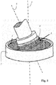
- Fig. 1 schematically illustrates the manufacture of the gearing 1, which has a total number of x teeth, for example, 101 teeth, and a gear pitch p, a gear 2 of a gear blank in the WälzWarl Kunststoff according to the prior art.
- the gear blank which has no teeth at the beginning, rotates about a first axis of rotation 3, while a tool gear 4, which has a counter toothing complementary to the toothing 5 to be rotated in synchronism with the rotation of the gear blank around a second axis of rotation 6, wherein the first axis of rotation 3 and the second axis of rotation 6 are skewed to each other, and wherein the tool gear 4 moves parallel to the first axis of rotation 3, while each already prepared part of the teeth 1 of the rotating gear blank and the counter teeth 5 of the rotating grinding tool 4 of the mesh with each other.
- Fig. 2 illustrates an embodiment relating to the inventive method for producing the toothing 1 of a gear 2, which has a module which is smaller than 0.5 mm or which is smaller than 0.25 mm or which is smaller than 0.15 mm.
- the counter-toothing 8 of the tool gear according to the invention 7 - in comparison to the in Fig. 1 shown tool gear 4 according to the prior art - only the half the number of teeth on.
- Each immediately adjacent teeth of the counter-toothing therefore have on the pitch circle a distance of n ⁇ p (n multiplied by p) to each other, in which case n is equal to 2. 101 and 2 are alien.
- the space between adjacent teeth of the tool gear 7 is a clearance.
- first tooth gaps of the toothing 1 are first of all partially produced, which are spaced apart by np (n multiplied by p), ie in the present case by 2p.
- np spaced apart by n multiplied by p
- the 1st, 3rd, 5th ... 99th and 101st tooth gaps are partially produced.
- second tooth gaps between the first tooth gaps are partially made, namely the 2, 4, 6 .... 98th and 100th tooth spaces.
- the first tooth gaps are further produced, in the fourth revolution, the second tooth gaps and so on until the entire toothing 1 is completely made.
- the rotation of the gear blank and the tool gear 7 is preferably not stopped until complete production of the toothing.
- the method according to the invention has the very special advantage that the tool gear 7 can be produced more easily, for example with conventional grinding technology, even with a very small gear pitch p, because the clearance between the teeth of the toothing 8 of the tool gear 7 according to the invention is also provided with relatively thick grinding wheels can be achieved.
Landscapes
- Engineering & Computer Science (AREA)
- Mechanical Engineering (AREA)
- Physics & Mathematics (AREA)
- Geometry (AREA)
- Gears, Cams (AREA)
Applications Claiming Priority (1)
| Application Number | Priority Date | Filing Date | Title |
|---|---|---|---|
| LU93122A LU93122B1 (de) | 2016-06-27 | 2016-06-27 | Zahnrad, Verfahren zum Herstellen der Verzahnung eines Zahnrades, sowie Werkzeugzahnrad zum Herstellen der Verzahnung eines Zahnrades |
Publications (1)
| Publication Number | Publication Date |
|---|---|
| EP3263261A1 true EP3263261A1 (fr) | 2018-01-03 |
Family
ID=56550938
Family Applications (1)
| Application Number | Title | Priority Date | Filing Date |
|---|---|---|---|
| EP17177950.7A Withdrawn EP3263261A1 (fr) | 2016-06-27 | 2017-06-26 | Roue dentée, procédé de fabrication de denture d'une roue dentée et outil destiné à fabriquer la denture d'une roue dentée |
Country Status (3)
| Country | Link |
|---|---|
| EP (1) | EP3263261A1 (fr) |
| DE (1) | DE102017114154A1 (fr) |
| LU (1) | LU93122B1 (fr) |
Cited By (1)
| Publication number | Priority date | Publication date | Assignee | Title |
|---|---|---|---|---|
| CN108672832A (zh) * | 2018-07-18 | 2018-10-19 | 重庆亨睿达机械有限公司 | 齿轮冷挤压用制造设备 |
Citations (16)
| Publication number | Priority date | Publication date | Assignee | Title |
|---|---|---|---|---|
| DE1115107B (de) * | 1960-02-09 | 1961-10-12 | I M S Joh Morat & Soehne Ges M | Waelzfraeser, insbesondere zur Herstellung von Zaehnen mit spitzen Profilen |
| DE1129359B (de) * | 1955-10-31 | 1962-05-10 | Nat Broach & Mach | Honwerkzeug zum Fertigbearbeiten von Zahnraedern |
| GB1157458A (en) * | 1966-07-01 | 1969-07-09 | Truninger Ag | Improvements relating to a Gear Pump. |
| DE3630912A1 (de) * | 1986-09-11 | 1988-03-24 | Esfira Efune | Waelzfraeser mit regulierter zahndicke |
| EP0625399A1 (fr) * | 1993-05-12 | 1994-11-23 | PRÄWEMA WERKZEUGMASCHINENFABRIK GmbH | Machine à fraise pivotante pour la fabrication des parties chaufreinées et des poches dans la denture intérieure d'un synchroniseur |
| JP2003314526A (ja) * | 2002-04-24 | 2003-11-06 | Morito Co Ltd | 茄子環及び茄子環付き締紐 |
| DE10329413A1 (de) * | 2003-07-01 | 2005-02-24 | Wera-Werk Hermann Werner Gmbh & Co. Kg | Verfahren zum Hinterlegen der Zähne verzahnter Werkstücke |
| EP1783402A1 (fr) * | 2005-11-04 | 2007-05-09 | Northrop Grumman Corporation | Transmission harmonique avec générateur d'ondes asymétrique et couronne flexible correpsondant |
| EP2422920A2 (fr) * | 2010-08-31 | 2012-02-29 | Aisin Seiki Kabushiki Kaisha | Appareil d'usinage d'engrenage, appareil de découpe et dispositif à engrenage d'onde de contrainte |
| EP2639001A1 (fr) * | 2012-03-14 | 2013-09-18 | Siemens Aktiengesellschaft | Procédé de traitement sous tension d'une pièce usinée |
| DE102012022439A1 (de) * | 2012-11-16 | 2014-05-22 | Marcel Sobczyk | Verfahren zur Bestimmung der Freiflächenkontur eines Wälzschälwerkzeuges, Wälzschälwerkzeug und dessen Verwendung |
| EP2745970A1 (fr) * | 2009-06-10 | 2014-06-25 | Profilator GmbH & Co. KG | Dispositif et procédé de décolletage en développante de roues dentées à engrenage intérieur et roue de décolletage associée |
| WO2014176169A2 (fr) * | 2013-04-22 | 2014-10-30 | The Gleason Works | Taillage de roues cylindriques |
| EP2839914A2 (fr) * | 2013-08-08 | 2015-02-25 | Jtekt Corporation | Appareil d'usinage à engrenage |
| DE102013225956A1 (de) * | 2013-12-13 | 2015-06-18 | Ovalo Gmbh | Fahrzeuglenkung mit einem Überlagerungssteller |
| US20150247563A1 (en) * | 2014-03-03 | 2015-09-03 | Harmonic Innovation Technology Co., Ltd. | High torque power module |
Family Cites Families (5)
| Publication number | Priority date | Publication date | Assignee | Title |
|---|---|---|---|---|
| DE243514C (de) | 1910-03-01 | 1912-02-16 | George Adams | Verfahren zum schneiden van zahnrädern mittels eines zahnradartigen, an den stirnflächen der zähne mit schneidkanten versehenen schneidwerkzeuges |
| DE102005049528A1 (de) | 2005-10-17 | 2007-05-10 | Profilator Gmbh & Co. Kg | Verfahren zum Herstellen von Schiebemuffen |
| DE102007015357B4 (de) | 2007-03-30 | 2023-03-23 | Profilator Gmbh & Co. Kg | Verfahren und Vorrichtung zum Verzahnen von Werkstücken durch Wälzschälen und zugehöriger Schneidvorrichtung |
| DE102008037514B4 (de) | 2008-11-03 | 2024-06-20 | Profilator Gmbh & Co. Kg | Wälzschälvorrichtung und -verfahren |
| LU92617B1 (de) * | 2014-12-16 | 2016-06-17 | Ovalo Gmbh | Verfahren und vorrichtung zum schleifenden bearbeiten der verzahnung eines zahnrades |
-
2016
- 2016-06-27 LU LU93122A patent/LU93122B1/de active IP Right Grant
-
2017
- 2017-06-26 EP EP17177950.7A patent/EP3263261A1/fr not_active Withdrawn
- 2017-06-26 DE DE102017114154.5A patent/DE102017114154A1/de not_active Withdrawn
Patent Citations (16)
| Publication number | Priority date | Publication date | Assignee | Title |
|---|---|---|---|---|
| DE1129359B (de) * | 1955-10-31 | 1962-05-10 | Nat Broach & Mach | Honwerkzeug zum Fertigbearbeiten von Zahnraedern |
| DE1115107B (de) * | 1960-02-09 | 1961-10-12 | I M S Joh Morat & Soehne Ges M | Waelzfraeser, insbesondere zur Herstellung von Zaehnen mit spitzen Profilen |
| GB1157458A (en) * | 1966-07-01 | 1969-07-09 | Truninger Ag | Improvements relating to a Gear Pump. |
| DE3630912A1 (de) * | 1986-09-11 | 1988-03-24 | Esfira Efune | Waelzfraeser mit regulierter zahndicke |
| EP0625399A1 (fr) * | 1993-05-12 | 1994-11-23 | PRÄWEMA WERKZEUGMASCHINENFABRIK GmbH | Machine à fraise pivotante pour la fabrication des parties chaufreinées et des poches dans la denture intérieure d'un synchroniseur |
| JP2003314526A (ja) * | 2002-04-24 | 2003-11-06 | Morito Co Ltd | 茄子環及び茄子環付き締紐 |
| DE10329413A1 (de) * | 2003-07-01 | 2005-02-24 | Wera-Werk Hermann Werner Gmbh & Co. Kg | Verfahren zum Hinterlegen der Zähne verzahnter Werkstücke |
| EP1783402A1 (fr) * | 2005-11-04 | 2007-05-09 | Northrop Grumman Corporation | Transmission harmonique avec générateur d'ondes asymétrique et couronne flexible correpsondant |
| EP2745970A1 (fr) * | 2009-06-10 | 2014-06-25 | Profilator GmbH & Co. KG | Dispositif et procédé de décolletage en développante de roues dentées à engrenage intérieur et roue de décolletage associée |
| EP2422920A2 (fr) * | 2010-08-31 | 2012-02-29 | Aisin Seiki Kabushiki Kaisha | Appareil d'usinage d'engrenage, appareil de découpe et dispositif à engrenage d'onde de contrainte |
| EP2639001A1 (fr) * | 2012-03-14 | 2013-09-18 | Siemens Aktiengesellschaft | Procédé de traitement sous tension d'une pièce usinée |
| DE102012022439A1 (de) * | 2012-11-16 | 2014-05-22 | Marcel Sobczyk | Verfahren zur Bestimmung der Freiflächenkontur eines Wälzschälwerkzeuges, Wälzschälwerkzeug und dessen Verwendung |
| WO2014176169A2 (fr) * | 2013-04-22 | 2014-10-30 | The Gleason Works | Taillage de roues cylindriques |
| EP2839914A2 (fr) * | 2013-08-08 | 2015-02-25 | Jtekt Corporation | Appareil d'usinage à engrenage |
| DE102013225956A1 (de) * | 2013-12-13 | 2015-06-18 | Ovalo Gmbh | Fahrzeuglenkung mit einem Überlagerungssteller |
| US20150247563A1 (en) * | 2014-03-03 | 2015-09-03 | Harmonic Innovation Technology Co., Ltd. | High torque power module |
Cited By (2)
| Publication number | Priority date | Publication date | Assignee | Title |
|---|---|---|---|---|
| CN108672832A (zh) * | 2018-07-18 | 2018-10-19 | 重庆亨睿达机械有限公司 | 齿轮冷挤压用制造设备 |
| CN108672832B (zh) * | 2018-07-18 | 2024-03-22 | 重庆亨科机械有限公司 | 齿轮冷挤压用制造设备 |
Also Published As
| Publication number | Publication date |
|---|---|
| DE102017114154A1 (de) | 2017-12-28 |
| LU93122B1 (de) | 2018-01-09 |
Similar Documents
| Publication | Publication Date | Title |
|---|---|---|
| EP2665574B1 (fr) | Procédé d'usinage d'une pièce par enlèvement de copeaux, et machine-outil mise au point à cette fin | |
| DE69735631T2 (de) | Apparat und verfahren zum präzisionsschleifen von kronenrädern | |
| EP3191248B1 (fr) | Dispositif de taillage en développante d'une pièce pour la production d'un chanfrein et procédé de fonctionnement associé | |
| EP3129181B1 (fr) | Procédé et dispositifs pour dresser des meules (vis sans fin) de manière rapide et flexible | |
| EP3043945B1 (fr) | Procédé de décolletage en développante, et dispositif correspondant | |
| EP2440357A1 (fr) | Procédé et dispositif de taillage en développante de pignons à denture intérieure, et roue de taillage associée | |
| EP0550877B1 (fr) | Procédé pour la génération des parties chanfreinées dans des dentures droites inférieures ou extérieures des pièces dentées | |
| EP3263260A1 (fr) | Roue dentée, procédé de fabrication de denture d'une roue dentée et outil destiné à fabriquer la denture d'une roue dentée | |
| WO2012152659A1 (fr) | Procédé de décolletage en développante et dispositif correspondant doté d'un outil de décolletage en développante | |
| WO2007045610A1 (fr) | Procede pour produire des coulisseaux | |
| WO2016150666A1 (fr) | Procédé servant à tailler des dents avec un usinage ultérieur de dents et outil combiné associé | |
| EP3993940B1 (fr) | Procédé permettant la réalisation de modifications de flancs de dent sur des dentures de pièces | |
| EP4114604B1 (fr) | Procédé d'usinage par enlèvement de copeaux d'une zone de flanc de dent d'une denture de pièce à usiner, utilisation d'un outil de chanfreinage, programme de commande comportant des indications de commande pour exécuter le procédé, et machine à tailler les dentures | |
| EP2929970B1 (fr) | Procédé d'usinage d'une pièce à usiner d'une roulette de dressage | |
| EP1841557B1 (fr) | Procede de fabrication de roues dentees | |
| EP1097772B1 (fr) | Génération de structures périodiques sur des pièces ayant une symétrie de révolution | |
| EP2851150A2 (fr) | Outil, procédé et machine destinés à fabriquer un profil denté sur une pièce par taillage des engrenages par développante | |
| LU93123B1 (de) | Spannungswellengetriebe, Zahnrad für ein Spannungswellengetriebe, und Verfahren zum Herstellen der Verzahnung eines Zahnrades für ein Spannungswellengetriebe | |
| EP3322552B1 (fr) | Procédé de finition d'une denture, machine de finition pour la mise en uvre du procédé et programme informatique pour la commande de la machine | |
| LU93122B1 (de) | Zahnrad, Verfahren zum Herstellen der Verzahnung eines Zahnrades, sowie Werkzeugzahnrad zum Herstellen der Verzahnung eines Zahnrades | |
| DE4030789B4 (de) | Verfahren und Vorrichtung zur Herstellung eines Hauptrotors | |
| DE102014118703A1 (de) | Verfahren und Vorrichtung zum schleifenden Bearbeiten der Verzahnung eines Zahnrades | |
| DE1961606A1 (de) | Verfahren und Vorrichtung zum Formen von Zahnradzaehnen | |
| EP3976303B1 (fr) | Fraise à tailler des engrenages et procédé pour fabriquer un engrenage à double denture hélicoïdale, ainsi qu'utilisation de la fraise à tailler des engrenages pour produire l'engrenage à double denture hélicoïdale | |
| EP3034220A1 (fr) | Dispositif et procede d'usinage de denture d'une roue dentee par enlevement de copeaux |
Legal Events
| Date | Code | Title | Description |
|---|---|---|---|
| PUAI | Public reference made under article 153(3) epc to a published international application that has entered the european phase |
Free format text: ORIGINAL CODE: 0009012 |
|
| STAA | Information on the status of an ep patent application or granted ep patent |
Free format text: STATUS: THE APPLICATION HAS BEEN PUBLISHED |
|
| AK | Designated contracting states |
Kind code of ref document: A1 Designated state(s): AL AT BE BG CH CY CZ DE DK EE ES FI FR GB GR HR HU IE IS IT LI LT LU LV MC MK MT NL NO PL PT RO RS SE SI SK SM TR |
|
| AX | Request for extension of the european patent |
Extension state: BA ME |
|
| STAA | Information on the status of an ep patent application or granted ep patent |
Free format text: STATUS: REQUEST FOR EXAMINATION WAS MADE |
|
| 17P | Request for examination filed |
Effective date: 20180622 |
|
| RBV | Designated contracting states (corrected) |
Designated state(s): AL AT BE BG CH CY CZ DE DK EE ES FI FR GB GR HR HU IE IS IT LI LT LU LV MC MK MT NL NO PL PT RO RS SE SI SK SM TR |
|
| STAA | Information on the status of an ep patent application or granted ep patent |
Free format text: STATUS: EXAMINATION IS IN PROGRESS |
|
| 17Q | First examination report despatched |
Effective date: 20210617 |
|
| STAA | Information on the status of an ep patent application or granted ep patent |
Free format text: STATUS: THE APPLICATION IS DEEMED TO BE WITHDRAWN |
|
| 18D | Application deemed to be withdrawn |
Effective date: 20211028 |