EP2422920A2 - Appareil d'usinage d'engrenage, appareil de découpe et dispositif à engrenage d'onde de contrainte - Google Patents
Appareil d'usinage d'engrenage, appareil de découpe et dispositif à engrenage d'onde de contrainte Download PDFInfo
- Publication number
- EP2422920A2 EP2422920A2 EP11177953A EP11177953A EP2422920A2 EP 2422920 A2 EP2422920 A2 EP 2422920A2 EP 11177953 A EP11177953 A EP 11177953A EP 11177953 A EP11177953 A EP 11177953A EP 2422920 A2 EP2422920 A2 EP 2422920A2
- Authority
- EP
- European Patent Office
- Prior art keywords
- gear
- cutter
- region
- work
- tooth
- Prior art date
- Legal status (The legal status is an assumption and is not a legal conclusion. Google has not performed a legal analysis and makes no representation as to the accuracy of the status listed.)
- Granted
Links
- 238000003754 machining Methods 0.000 title claims abstract description 107
- 230000007246 mechanism Effects 0.000 claims abstract description 23
- 238000009751 slip forming Methods 0.000 claims abstract description 8
- 208000015375 Reduced number of teeth Diseases 0.000 claims description 2
- 238000005520 cutting process Methods 0.000 description 13
- 238000010276 construction Methods 0.000 description 11
- 230000001360 synchronised effect Effects 0.000 description 8
- 230000008859 change Effects 0.000 description 7
- 238000012986 modification Methods 0.000 description 6
- 230000004048 modification Effects 0.000 description 6
- 230000004044 response Effects 0.000 description 6
- 238000004519 manufacturing process Methods 0.000 description 5
- 230000002349 favourable effect Effects 0.000 description 4
- 239000006185 dispersion Substances 0.000 description 3
- 238000000034 method Methods 0.000 description 3
- 230000007423 decrease Effects 0.000 description 2
- 230000009467 reduction Effects 0.000 description 2
- 230000000452 restraining effect Effects 0.000 description 2
- 230000005540 biological transmission Effects 0.000 description 1
- 238000010586 diagram Methods 0.000 description 1
- 238000006073 displacement reaction Methods 0.000 description 1
- 230000000694 effects Effects 0.000 description 1
- 230000005489 elastic deformation Effects 0.000 description 1
- 230000008569 process Effects 0.000 description 1
- 230000010349 pulsation Effects 0.000 description 1
Images


Classifications
-
- B—PERFORMING OPERATIONS; TRANSPORTING
- B23—MACHINE TOOLS; METAL-WORKING NOT OTHERWISE PROVIDED FOR
- B23F—MAKING GEARS OR TOOTHED RACKS
- B23F5/00—Making straight gear teeth involving moving a tool relatively to a workpiece with a rolling-off or an enveloping motion with respect to the gear teeth to be made
- B23F5/12—Making straight gear teeth involving moving a tool relatively to a workpiece with a rolling-off or an enveloping motion with respect to the gear teeth to be made by planing or slotting
- B23F5/16—Making straight gear teeth involving moving a tool relatively to a workpiece with a rolling-off or an enveloping motion with respect to the gear teeth to be made by planing or slotting the tool having a shape similar to that of a spur wheel or part thereof
- B23F5/163—Making straight gear teeth involving moving a tool relatively to a workpiece with a rolling-off or an enveloping motion with respect to the gear teeth to be made by planing or slotting the tool having a shape similar to that of a spur wheel or part thereof the tool and workpiece being in crossed axis arrangement, e.g. skiving, i.e. "Waelzschaelen"
-
- B—PERFORMING OPERATIONS; TRANSPORTING
- B23—MACHINE TOOLS; METAL-WORKING NOT OTHERWISE PROVIDED FOR
- B23F—MAKING GEARS OR TOOTHED RACKS
- B23F15/00—Methods or machines for making gear wheels of special kinds not covered by groups B23F7/00 - B23F13/00
-
- F—MECHANICAL ENGINEERING; LIGHTING; HEATING; WEAPONS; BLASTING
- F16—ENGINEERING ELEMENTS AND UNITS; GENERAL MEASURES FOR PRODUCING AND MAINTAINING EFFECTIVE FUNCTIONING OF MACHINES OR INSTALLATIONS; THERMAL INSULATION IN GENERAL
- F16H—GEARING
- F16H55/00—Elements with teeth or friction surfaces for conveying motion; Worms, pulleys or sheaves for gearing mechanisms
- F16H55/02—Toothed members; Worms
- F16H55/08—Profiling
- F16H55/0833—Flexible toothed member, e.g. harmonic drive
-
- Y—GENERAL TAGGING OF NEW TECHNOLOGICAL DEVELOPMENTS; GENERAL TAGGING OF CROSS-SECTIONAL TECHNOLOGIES SPANNING OVER SEVERAL SECTIONS OF THE IPC; TECHNICAL SUBJECTS COVERED BY FORMER USPC CROSS-REFERENCE ART COLLECTIONS [XRACs] AND DIGESTS
- Y10—TECHNICAL SUBJECTS COVERED BY FORMER USPC
- Y10T—TECHNICAL SUBJECTS COVERED BY FORMER US CLASSIFICATION
- Y10T409/00—Gear cutting, milling, or planing
- Y10T409/10—Gear cutting
- Y10T409/101431—Gear tooth shape generating
- Y10T409/107473—Making a noncircular gear, worm, rotor, or a planar-faced gear
Definitions
- This disclosure generally relates to a gear machining apparatus, a cutter, and a strain wave gearing device.
- a known gear machining apparatus which machines an internal spur gear by skiving, is disclosed in the following reference: KOJIMA Masakazu, and NISHIJIMA Komio. "Gear Skiving of Involute Internal Spur Gear: Part 1, On the Tooth Profile" Transactions of the Japan Society of Mechanical Engineers 39(324), 2580-2586 , (hereinafter referred to as non-patent reference 1).
- the non-patent reference 1 discloses that a tooth profile is defined by defining factors, for example, a rake angle of specifications for a cutter, a cutting angle, a rake face re-cutting amount, and a tooth number ratio.
- a skiving method for attaining high cutting efficiency when machining an internal spur gear, and modifications of tooth profile of a cutter is disclosed in the following reference: NISHIJIMA Komio, KOJIMA Masakazu, and YAMADA Toyo "Gear Skiving of Involute Internal Spur Gear: Part 2, On the Practical Problems" Transactions of the Japan Society of Mechanical Engineers 40(329), 260-268 , (hereinafter referred to as non-patent reference 2).
- JPH07-84896B discloses a flexible meshing type gear device as a gear device applied with the Internal gear.
- the flexible meshing type gear device includes a rigid circular internal gear, a flexible external gear arranged inside the internal gear, and a wave generator flexibly deforming and rotating the external gear in the deformed configuration.
- the gear device disclosed in the patent reference 1 is named as a strain wave gearing device in which the number of teeth of the external gear is defined to be less than the number of teeth of the internal gear, and only two teeth corresponding to positions of portions of an elliptic longitudinal shaft of a cam plate of the external gear engage with the teeth of the internal gear by the deformation of the external gear by the cam plate.
- the strain wave gearing device is configured to move a region to flex in response to the rotation of the cam plate by engaging a portion of the external gear to the Internal gear by flexing the external gear by the cam plate, the external gear and the internal gear are required to be formed with high precision.
- a gear shaper may be applied to machine the internal gear with high precision.
- the machining is achieved with high precision with the gear shaper, the machining time with the gear shaper is long thus increasing manufacturing costs of the strain wave gearing device.
- a skiving may be applied for machining the internal gear.
- the skiving is favorable for reducing the machining time of the internal gear because of high cutting efficiency. Notwithstanding, it has been considered that the machining with high precision is unlikely to be obtained by skiving.
- dispersions of the machining precisions are caused by variations of tooth profile of a machined work gear by, for example, errors in cutter production, setting errors of machining machine, and when putting an edge on the cutter, which are necessary for normal production activities.
- the references disclose that the errors in the tooth profile cause a tendency similar to the case where the radius of the base circle of the cutter is varied.
- the disclosure provides a gear machining apparatus, which includes a skiving mechanism positioning a work to be machined and a pinion type cutter on axes skewing from each other, the skiving mechanism rotating the work at a predetermined position and feeding the cutter while rotating in a direction of a tooth trace of a gear to be formed at the work synchronously to the rotation of the work for producing the gear from the work.
- the cutter includes a tooth surface which is formed with an involute region having an involute curve in an area including a pitch circle in a tooth depth direction, an addendum region continuously formed from the involute region to an addendum, and a dedendum region continuously formed from the involute region to a dedendum, the addendum region and the dedendum region being shaped in a configuration different from the involute region.
- a tooth surface of the cutter configured based on an involute curve is formed as an involute region at a portion including a pitch circle so that a change In a tooth profile which is to be formed on a work is assumed to be small even if a position of the cutter serving as a parameter is changed. Further, by forming portions of the tooth surface positioned at the addendum side and at the dedendum, side relative to the involute region in configurations different from the configuration of the involute region, declination of a performance of a gear produced by the machining is restrained while attaining a machining with high precision. Accordingly, the gear machining apparatus is configured to attain machining with high precision while restraining the influence on tooth surface configurations of the cutter even if a machining parameter is changed when machining a gear by skiving.
- a value obtained by dividing an average radius of the involute region by a radius of a base circle is defined to be greater than one and smaller than one point one.
- a tooth depth is assumed to be adequately short relative to a radius of a base circle of the cutter.
- a configuration of the cutter is approximate to a configuration of a rack type cutter, and in consequence, a variation of a gear profile to be formed on a work is reduced even if positions of the cutter relative to the work changes to some extent when the cutter actuates.
- the involute region is determined to be equal to or greater than ten percent and less than eighty-five percent of an entire tooth depth in a tooth depth direction.
- the involute region is formed within a relatively small region, which is equal to or greater than ten percent (10 %) and less than eighty-five percent (85 %) of the entire tooth depth in the direction of the tooth depth, a drawback to decline a performance of a gear engagement of a gear produced by machining is solved.
- a cutter applied to a gear machining apparatus in a case where a tooth number of a gear to be formed on the work is defined as Zw and a tooth number of the cutter is defined as Zc, a ratio Zc / Zw between the cutter tooth number Zc and the work tooth number Zw is set within a range of being greater than 1/4 and being smaller than 2/3 when the gear to be formed on the work is an internal gear and a ratio Zc / Zw between the cutter tooth number Zc and the work tooth number Zw is set within a range of being greater than 1/2 and being smaller than 3 when the gear to be formed on the work is an external gear.
- a value obtained by dividing an average radius of an involute region of the cutter by a radius of a base circle is defined to be greater than one and smaller than one point one.
- the tooth depth is assumed to be adequately short relative to the radius of the base circle.
- the cutter includes a configuration similar to a rack type cutter, and a variation of the tooth profile of the gear to be formed on a work is assumed to be small even if a position of the cutter relative to the work is varied to some extent when the cutter is actuated.
- the involute region of the cutter is determined to be equal to or greater than ten percent and less than eighty-five percent of an entire tooth depth in a tooth depth direction.
- the involute region is formed within a relatively small region, which is equal to or greater than ten percent (10 %) and less than eighty-five percent (85 %) of the entire tooth depth in the direction of the tooth depth, a drawback to decline a performance of a gear engagement of a gear produced by machining is solved.
- a strain wave gearing device includes an internal gear produced by a gear machining apparatus according to claim 1, and an external gear having a reduced number of teeth compared to the internal gear, the external gear being flexible. A part of teeth of the internal gear is engaged with a part of teeth of the external gear by flexing the external gear, and the internal gear and the external gear relatively rotate by rotating a flexed portion of the external gear.
- the Involute region having an involute curve is formed within the region including the pitch circle in the tooth depth direction on the internal gear, and the addendum region and the dedendum region having the tooth surface configuration different from the configuration of the Involute region are formed at the addendum side and the dedendum side, respectively.
- the strain wave gearing device is not configured to perform a simple rotational movement and is configured to move the engaging positions of the internal gear and the external gear by a relative displacement of the internal gear and the external gear while the external gear elastically deforms in the tooth depth direction relative to the internal gear.
- the strain wave gearing device is different from the construction which transmits the rotational force while maintaining the engagement of the teeth of the internal gear and the external gear. That is, according to gear pairs which transmit the rotational force in a state where the internal gear and the external gear are engaged, a dimension of contact area of the internal gear and the external gear is great compared to that of the strain wave gearing device. According to the foregoing reasons, as long as the tooth surface configuration of the internal gear is formed so that the involute surface is provided in the area (region) of the tooth of the internal gear which contacts the external gear an adequate engaging performance is ensured, and the area (region) of the tooth of the internal gear at which the involute surface is provided can be reduced in the tooth depth direction compared to a normal internal gear.
- the number of the teeth of the internal gear applied to the strain wave gearing device is significantly large, the number z of the tooth of the cutter for machining the internal gear is increased.
- the strain wave gearing device including the internal gear with high precision is attained.
- a life span of the cutter is enhanced by reducing a machining load applied per each tooth of the cutter so that the number of work gears to be machined by the same cutter is increased.
- the engaging rate between the cutter and the work gear i.e., the gear to be formed on the work
- fluctuations (pulsation) of the machining movement is reduced to further enhance the machining precision and to enhance the life span of the cutter.
- Fig. 1 is a perspective view showing a machining process by a gear machining apparatus according to a first embodiment disclosed here;
- Fig. 2 is a block diagram showing a structure of a gear machining mechanism
- Fig. 3 is a view showing a tooth profile of a cutter according to the first embodiment disclosed here;
- Fig. 4 is a view showing a tooth profile of a cutter according to another embodiment disclosed here.
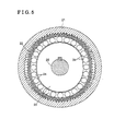
- Fig. 5 is a cross-sectional view showing a structure of a strain wave gearing device according to the embodiments disclosed here.
- the gear machining apparatus disclosed here includes a table 2 supporting a work 1 which is an object to be machined and is rotatable about a vertical axis Y, a pinion type cutter 3 rotatably supported about a machining axis X, and an operation portion 4 rotatably supporting the cutter 3 and movable in directions of tooth trace of a gear to be formed at the work 1.
- a skiving processing mechanism is structured with the table 2, the cutter 3, and the operation portion 4.
- the gear machining apparatus includes a synchronous drive mechanism 5 synchronously rotating the table 2 and the cutter 3, a cutting drive mechanism 6 moving the operation portion 4 in the directions of a tooth trace of the gear to be formed at the work 1, and a control mechanism 7 for controlling an electric motor 5M transmitting a drive force to the synchronous drive mechanism 5 and an electric motor 6M transmitting a drive force to the cutting drive mechanism 6.
- An angle of the machining axis X with reference to the vertical axis Y is defined as an inclination angle a
- a rotational amount per unit time of the cutter 3 is defined as a cutter rotational amount c
- a depth of cut (an engaging amount) of the work 1 by the cutter 3 is defined as a cutting amount x
- a moving amount (a distance) of the cutter 3 in a direction of the vertical axis Y is defined as a cutter feed amount z
- a rotational amount per unit time of the work 1 (the work gear) is defined as a work rotational amount w.
- the inclination angle a, the cutter rotational amount c, the cutting amount x, the cutter feed amount z, and the work rotational amount w are part of parameters defined when machining a gear by the gear machining apparatus.
- the synchronous drive mechanism 5 is configured to be actuated by the single electric motor 5M and includes plural gears and shafts which cooperatively rotate so that the work rotational amount w of the work 1 and the cutter rotational amount c of the cutter 3 establish a predetermined relationship.
- the synchronous drive mechanism 5 may include two synchronous type electric motors for independently actuating the table 2 and the cutter 3, the control mechanism 7 may output a synchronous signal to two electric motors.
- the operational portion 4 includes a slider 4B movable along a guide body 4A to move the cutter 3 by the desired cutter feed amount z, and an arm 4D connecting to the slider 4B via a joint 4C allowing an angle of the arm 4D relative to the slider 4B to be adjustable so that the cutting amount x is determined as desired.
- An end of the arm 4D is connected to a frame portion 3A which rotatably supports the cutter 3, thus a drive force of the cutting drive mechanism 6 is transmitted to the slider 48.
- Adjustment of an angle of the guide body 4A and settings of an angle (the inclination angle a) of the machining axis X by the joint 4C of the operational portion 4 is manually defined and fixed, however, the angle of the guide body 4A and the angle (the inclination angle a) of the machining axis X may be adjusted by an electric motor.
- Constructions of the operational portion 4 are not limited to the construction shown in the drawings, and, for example, the inclination angle a may be determined by plural joints likewise a robot arm with multiple joints and the cutter 3 may be moved by the cutter feed amount z in the direction of the tooth trace of the gear to be formed on the work 1 by an operation of the robot arm.
- the control mechanism 7 is configured to perform a calculating transaction and a controlling transaction following a predetermined program set in, for example, a micro-processor.
- the control mechanism 7 is configured to control the electric motors 5M, 6M.
- the gear machining apparatus is named as a skiving apparatus.
- Drawings show a machining process for manufacturing an internal gear 21 (work gear) by cutting the work 1 by the cutter 3.
- the vertical axis Y is set to be arranged in a vertical direction and the machining axis X is set in a predetermined inclined attitude.
- the work 1 is rotated by the synchronous drive mechanism 5 at a fixed position together with the table 2 about the vertical axis Y, and synchronous to the rotation of the work 1 about the vertical axis Y the cutter 3 is rotated about the machining axis X.
- an involute region 12 having an involute profile (surface) 10P which includes an involute curve at a portion of a tooth 10 of the cutter 3 at a position including a pitch circle 11.
- the tooth 10 of the cutter 3 includes an addendum region 13 including an addendum surface 10T having a curved surface at an addendum side relative to the involute region 12 and a dedendum region 14 having a dedendum surface 10B having a curved surface at a dedendum side relative to the involute region 12.
- the addendum surface 10T and the dedendum surface 10B are formed continuously from the involute profile (surface) 10P, however, formed in different configurations from an involute curve.
- a change in a base circle (i.e., one of parameters) of the cutter 3 defined as a gear may become necessary for the modifications of the cutter 3. This is because a difference of the base circles influence on an error in a machined tooth profile to a large extent, and according to the gear machining apparatus for performing a normal skiving process, a common cutter cannot be applied as the cutter 3 to works on which gears having different specifications to be formed, that is, to produce gears having different specifications. On the other hand, according to the gear machining apparatus of the disclosure, a common cutter can be applied to produce gears having a slight difference in the teeth number.
- the common cutter can be applied when machining works to produce gears having a tooth number difference by two.
- productivity can be enhanced while reducing manufacturing costs.
- an involute curve for a tooth is calculated on the basis of a base circle 15 according to the cutter 3, a tooth surface configuration of different involute curves is determined every time a base circle radius Rg of the base circle 15 changes.
- the gear machining apparatus disclosed here defines a relationship between the base circle radius Rg and an average radius Rd of the involute region 12 as shown in formula 1 so that a change in the involute surface of a tooth surface is assumed to be relatively small even if the base circle radius Rg of the base circle is changed and the cutter 3 does not require modifications.
- a value dividing the average radius Rd of the involute region 12 by the base circle radius Rg is defined to be greater than one (i.e., 1) and smaller than one point one (i.e., 1.1).
- the involute region 12 is defined to occupy sixty to seventy percent (60% to 70%) of en entire tooth depth in the tooth depth direction.
- the involute region 12 may be defined to be equal to or more than ten percent (10 %) of a tooth depth of the cutter 3 and to be less than eighty-five percent (85 %) of the tooth depth of the cutter 3.
- the involute surface 10P is formed in the involute region 12 of the cutter 3 and the involute surface 10P is formed within a region including a pitch circle in a tooth depth direction of the internal gear.
- a ratio of the cutter tooth number Zc and the work tooth number Zw is determined as follows.
- the ratio of the cutter tooth number Zc and the work tooth number Zw is set within a range as follows; 1/4 ⁇ Zc/Zw ⁇ 2/3.
- the ratio of the cutter tooth number Zc and the work tooth number Zw is set within a range as follows: 1/2 ⁇ Zc/Zw ⁇ 3.
- configurations of the tooth surfaces of the addendum region 13 and the dedendum region 14 are formed in configurations different from the involute surface.
- the configurations of the addendum region 13 and the dedendum region 14 are not limited.
- the addendum region 13 may be formed to have an arc surface 13S having a radius R and the dedendum region 14 may be formed to have an arc surface 14S having a radius R.
- durability of the cutter 3 may be enhanced by forming the addendum region 13 and the dedendum region 14 in the arc surfaces 13S, 14S.
- Fig. 5 shows the strain wave gearing device which includes the internal gear 21 machined by the gear machining apparatus explained above, the flexible external gear 22 including a reduced number of the teeth than the internal gear 21, an elliptic cam 23, and plural balls 24 arranged being sandwiched between the elliptic cam 23 and the external gear 22.
- the external gear 22 can be machined and the machining precisions when machining the external gear 22 with the gear machining apparatus is as precise as the case where the internal gear is machined by the gear machining apparatus.
- the external gear 22 applied to the strain wave gearing device may be machined by the gear machining apparatus.
- the tooth number of the internal gear 21 may be determined to be equal to or greater than fifty (50), and may preferably be determined to exceed two hundreds (200).
- the strain wave gearing device is configured to engage two teeth among the plural teeth of the external gear 22, which are positioned on an imaginary extended line of a longitudinal shaft of the elliptic cam 23, with the teeth of the internal gear 21.
- flexed portions of the external gear 22 are rotated to engage particular teeth among the plural teeth of the external gear 22, which are positioned on the imaginary extended line of the longitudinal shaft of the elliptic cam 23, with the teeth of the internal gear 21, thus relatively rotating the internal gear 21 and the external gear 22 in order for a speed reduction.
- the machining method of the external tooth 22 is not limited to the machining by the gear machining apparatus, and, for example, may be machined by a hobbing machine.
- the involute surface is formed at the region including the pitch circle 11 in the tooth depth direction, however, the involute region in which the involute surface is formed is short in the tooth depth direction.
- a meshing performance is not favorable when the internal gear is applied to, for example, a ring gear of a sun gear.
- the internal gear 21 machined by the gear machining apparatus explained above is applied to the strain wave gearing device, a meshing performance of the engagement between the internal gear 21 and the external gear 22 is ensured.
- the strain wave gearing device is not configured to perform a simple rotational movement and is configured to move the meshing position by relatively displacing the internal gear 21 and the external gear 22 while the external gear is elastically deformed relative to the internal gear in the tooth depth direction in a state where a part of the multiple number of the teeth of the internal gear 21 and a part of the multiple number of the teeth of the external gear 22 are engaged, a transmission structure is different from the construction in which the rotational force is transmitted while maintaining the engaged state of the teeth of the internal gear and the teeth of the external gear.
- the gear machining apparatus disclosed here is suitable for machining the internal gear 21 of the strain wave gearing device.
- a value of the base circle radius Rg may be increased by increasing a value of the pressure angle ⁇ (for example, eleven degrees (11°) to twenty-five degrees (25°)) of the cutter 3 and by increasing the tooth number z of the pinion type cutter 3 in accordance with the tooth number of the internal gear 21, which exceeds two hundred (200).
- an involute surface is formed on the internal gear 21.
- the region of the involute surface 10P of the cutter 3 is assumed to be about ten percent (10 %) minimally in the tooth depth direction
- the region of the involute surface at the tooth of the internal gear 21 is assumed to be about ten percent (10%).
- the strain wave gearing device is configured to move the engaging position while the internal gear 21 and the external gear 22 relatively displace each other in the tooth depth direction by an elastic deformation of the external gear 22 relative to the internal gear 21, the involute surfaces of the respective gears are not necessary to continuously contact each other to transmit the drive force, and thus the engagements with adequate meshing performance is attained.
- a curved surface in which an involute and a curve similar to an involute are combined may be adopted, and a performance may be enhanced by applying the curved surface explained above.
- a gear machining apparatus includes a skiving mechanism positioning a work (1) to be machined and a pinion type cutter (3) on axes skewing from each other, the skiving mechanism rotating the work at a predetermined position and feeding the cutter while rotating in a direction of a tooth trace of a gear to be formed at the work synchronously to the rotation of the work for producing the gear from the work.
- the cutter includes a tooth surface which is formed with an involute region (12) having an involute curve in an area including a pitch circle (11) in a tooth depth direction, an addendum region (13) continuously formed from the involute region to an addendum, and a dedendum region (14) continuously formed from the involute region to a dedendum, the addendum region and the dedendum region being shaped in a configuration different from the involute region.
Landscapes
- Engineering & Computer Science (AREA)
- Mechanical Engineering (AREA)
- Gear Processing (AREA)
- Retarders (AREA)
Applications Claiming Priority (1)
| Application Number | Priority Date | Filing Date | Title |
|---|---|---|---|
| JP2010194213A JP5776924B2 (ja) | 2010-08-31 | 2010-08-31 | 歯車加工装置、カッター、及び波動歯車装置 |
Publications (3)
| Publication Number | Publication Date |
|---|---|
| EP2422920A2 true EP2422920A2 (fr) | 2012-02-29 |
| EP2422920A3 EP2422920A3 (fr) | 2012-08-01 |
| EP2422920B1 EP2422920B1 (fr) | 2013-08-07 |
Family
ID=45045267
Family Applications (1)
| Application Number | Title | Priority Date | Filing Date |
|---|---|---|---|
| EP11177953.4A Revoked EP2422920B1 (fr) | 2010-08-31 | 2011-08-18 | Appareil d'usinage d'engrenage et dispositif à engrenage d'onde de contrainte |
Country Status (3)
| Country | Link |
|---|---|
| US (1) | US9327357B2 (fr) |
| EP (1) | EP2422920B1 (fr) |
| JP (1) | JP5776924B2 (fr) |
Cited By (8)
| Publication number | Priority date | Publication date | Assignee | Title |
|---|---|---|---|---|
| DE102013108286A1 (de) * | 2013-08-01 | 2015-02-05 | Harmonic Drive Ag | Verfahren zum Herstellen eines elastischen, eine Verzahnung aufweisenden Verzahnbauteils eines Wellgetriebes |
| EP2845675A2 (fr) | 2013-08-27 | 2015-03-11 | Sandvik Intellectual Property AB | Outil et plaquette de coupe au taillage |
| US20160067804A1 (en) * | 2014-09-04 | 2016-03-10 | Eaton Corporation | Modified tooth proportion gear cutter |
| US9327358B2 (en) | 2013-02-15 | 2016-05-03 | Aisin Seiki Kabushiki Kaisha | Method for processing gear and cutter for processing gear |
| DE102014118703A1 (de) * | 2014-12-16 | 2016-06-16 | Ovalo Gmbh | Verfahren und Vorrichtung zum schleifenden Bearbeiten der Verzahnung eines Zahnrades |
| EP3263260A1 (fr) * | 2016-06-27 | 2018-01-03 | Ovalo GmbH | Roue dentée, procédé de fabrication de denture d'une roue dentée et outil destiné à fabriquer la denture d'une roue dentée |
| EP3263261A1 (fr) * | 2016-06-27 | 2018-01-03 | Ovalo GmbH | Roue dentée, procédé de fabrication de denture d'une roue dentée et outil destiné à fabriquer la denture d'une roue dentée |
| WO2021001055A1 (fr) * | 2019-07-02 | 2021-01-07 | Rheinisch-Westfälische Technische Hochschule (Rwth) Aachen | Procédé permettant la réalisation de modifications de flancs de dent sur des dentures de pièces et outils permettant la mise en œuvre du procédé |
Families Citing this family (20)
| Publication number | Priority date | Publication date | Assignee | Title |
|---|---|---|---|---|
| US9154015B2 (en) * | 2010-03-24 | 2015-10-06 | Asmo Co., Ltd. | Speed reduction mechanism, motor with speed reduction mechanism, and method for producing speed reduction mechanism |
| JP6094093B2 (ja) * | 2012-08-21 | 2017-03-15 | アイシン精機株式会社 | スカイビング加工用カッター |
| JP5846082B2 (ja) | 2012-08-30 | 2016-01-20 | アイシン精機株式会社 | スカイビング加工用カッターの研削方法 |
| US9956627B2 (en) * | 2013-04-22 | 2018-05-01 | The Gleason Works | Skiving of cylindrical gears |
| JP6340764B2 (ja) | 2013-08-08 | 2018-06-13 | 株式会社ジェイテクト | 歯車加工装置 |
| JP6140585B2 (ja) * | 2013-09-19 | 2017-05-31 | 三菱重工工作機械株式会社 | 内歯車加工機械及び内歯車加工方法 |
| JP6275588B2 (ja) * | 2013-12-25 | 2018-02-07 | 住友重機械工業株式会社 | 遊星歯車装置およびその内歯歯車の製造方法 |
| JP6330443B2 (ja) * | 2014-04-16 | 2018-05-30 | アイシン精機株式会社 | スカイビング用カッター、及び歯車 |
| JP6620393B2 (ja) | 2014-05-19 | 2019-12-18 | 株式会社ジェイテクト | 歯車加工方法 |
| JP6780265B2 (ja) * | 2016-03-09 | 2020-11-04 | 株式会社ジェイテクト | 工作機械のチルト装置 |
| CN108679190B (zh) * | 2018-06-06 | 2024-05-24 | 重庆大学 | 新型柔性补偿型齿轮机器人减速器 |
| CN109352092B (zh) * | 2018-12-12 | 2019-12-20 | 重庆克利加工具制造有限公司 | 强力切齿刀设计方法 |
| JP7532848B2 (ja) * | 2019-07-08 | 2024-08-14 | 株式会社ジェイテクト | 歯車加工支援装置及び歯車加工装置 |
| DE102019126870A1 (de) | 2019-10-07 | 2021-04-08 | Präwema Antriebstechnik GmbH | Schälrad und verfahren zum herstellen einer verzahnung an einem zahnrad durch wälzschälen |
| WO2022091384A1 (fr) * | 2020-10-30 | 2022-05-05 | 株式会社ハーモニック・ドライブ・システムズ | Dispositif d'engrenage à ondes pourvu d'un profil de dent tridimensionnelle |
| JP2023178739A (ja) * | 2022-06-06 | 2023-12-18 | 株式会社不二越 | 歯車製造方法 |
| US12461330B2 (en) * | 2022-10-24 | 2025-11-04 | Meta Platforms Technologies, Llc | Eye relief adjustment mechanism and headset display device including eye relief adjustment mechanism |
| CN116810053B (zh) * | 2023-07-03 | 2025-09-23 | 燕山大学 | 一种基于盘形刀具的非圆面齿轮展成加工装置及其方法 |
| CN117102813B (zh) * | 2023-08-29 | 2026-04-03 | 中国第一汽车股份有限公司 | 一种分动器球凸轮加工方法 |
| JP7735608B1 (ja) * | 2025-06-26 | 2025-09-08 | Dmg森精機株式会社 | 情報処理装置、工作機械および情報処理方法 |
Family Cites Families (41)
| Publication number | Priority date | Publication date | Assignee | Title |
|---|---|---|---|---|
| DE243514C (de) | 1910-03-01 | 1912-02-16 | George Adams | Verfahren zum schneiden van zahnrädern mittels eines zahnradartigen, an den stirnflächen der zähne mit schneidkanten versehenen schneidwerkzeuges |
| AT59866B (de) | 1912-01-23 | 1913-06-25 | Max Maag | Verfahren zur Erzeugung beliebiger Evolventenverzahnungen für Stirn-, Kegel- und Schraubenräder mittels nach dem Abwälzverfahren arbeitender Fräs-, Hobel- oder Schleifmaschinen. |
| US1221613A (en) * | 1916-07-17 | 1917-04-03 | Oliver G Simmons | Formed milling-cutter. |
| DE423518C (de) | 1923-10-07 | 1926-01-05 | Friedrich Stolzenberg & Co G M | Verfahren zum Erzeugen von Evolventenverzahnungen mit Zahnhoehenkorrektion |
| DE471121C (de) | 1924-05-24 | 1929-02-07 | Hermann Hofer | Evolventenverzahnung |
| CH124186A (de) | 1926-07-06 | 1928-01-16 | Aktiengesellscha Zahnradfabrik | Evolventenverzahnung. |
| DE512450C (de) | 1928-09-09 | 1930-11-12 | Hammar Co Inc | Getriebezahn |
| DE608877C (de) | 1929-11-22 | 1935-02-07 | Richard Herrmann | Werkzeug zum Erzeugen von Evolventenverzahnungen an Zahnraedern |
| AT144253B (de) | 1933-11-01 | 1936-01-10 | Parson Marine Steam Turbine Co | Evolventenverzahnung. |
| US2202407A (en) * | 1937-11-24 | 1940-05-28 | William E Sykes | Gear cutter |
| US2308891A (en) | 1939-04-05 | 1943-01-19 | Fellows Gear Shaper Co | Method and apparatus for gear generation |
| US2354670A (en) * | 1939-10-23 | 1944-08-01 | Robert S Drummond | Gear finishing |
| US2392803A (en) * | 1943-09-10 | 1946-01-15 | Nat Broach & Mach | Gear finishing |
| GB601758A (en) | 1945-02-08 | 1948-05-12 | Fellows Gear Shaper Co | Method of finishing gears |
| BE546257A (fr) | 1955-03-21 | |||
| DE1070901B (fr) | 1958-04-09 | 1959-12-10 | ||
| US3180227A (en) * | 1962-06-22 | 1965-04-27 | Schlichthorlein Johann | Gear teeth finishing |
| US4066001A (en) | 1974-11-12 | 1978-01-03 | Kabushiki Kaisha Komatsu Seisakusho | Skiving cutter for use in cutting internal spur gear |
| JPS61226220A (ja) * | 1985-03-30 | 1986-10-08 | Agency Of Ind Science & Technol | 増減速駆動機用歯車の創成歯切法 |
| DE3533064A1 (de) * | 1985-09-17 | 1987-03-26 | Pfauter Hermann Gmbh Co | Verfahren zur bearbeitung der flanken von zahnraedern durch waelzschaelen sowie vorrichtung zur durchfuehrung eines solchen verfahrens |
| US4663813A (en) * | 1986-01-22 | 1987-05-12 | Usm Corporation | Method of making an internal wave generator for strain wave gearing |
| JPH0784896B2 (ja) | 1986-11-05 | 1995-09-13 | 株式会社ハーモニック・ドライブ・システムズ | 撓み噛み合い式歯車装置 |
| PL146060B2 (en) * | 1986-12-17 | 1988-12-31 | Gear transmission with variable pressure angle and method of machining tooth profiles of such gear | |
| JPH01159126A (ja) * | 1987-12-14 | 1989-06-22 | Mitsubishi Heavy Ind Ltd | スカイビング盤 |
| JP2528519B2 (ja) * | 1989-07-27 | 1996-08-28 | 日産自動車株式会社 | 歯車の加工方法 |
| JPH0732215A (ja) * | 1993-07-21 | 1995-02-03 | Kobe Steel Ltd | ピニオンカッタおよびその製造方法 |
| JPH0784896A (ja) | 1993-09-20 | 1995-03-31 | Fujitsu Ltd | シリアルデータの転送回路 |
| DE19501016A1 (de) | 1995-01-14 | 1996-07-18 | Zahnradfabrik Friedrichshafen | Evolventenverzahnung |
| DE19509448A1 (de) | 1995-03-16 | 1995-11-30 | Kurt G Dipl Ing Fickelscher | Die Verzahnungsgeometrie wird mathematisch so bestimmt, daß die relative Flankenwinkeländerung durch die Einlaufwinkeländerung aufgehoben oder ausgeglichen wird |
| DE29614738U1 (de) | 1996-08-24 | 1996-10-24 | Hirn, Helmut, Dipl.-Ing., 72147 Nehren | Untersetzungsgetriebe |
| DE29622185U1 (de) | 1996-12-20 | 1998-07-30 | Hirn, Marliese, 72147 Nehren | Untersetzungsgetriebe |
| JP4392771B2 (ja) | 1999-11-22 | 2010-01-06 | 株式会社ハーモニック・ドライブ・システムズ | 偏位かみ合いインボリュート歯形を有する撓みかみ合い式歯車装置 |
| US6799489B2 (en) | 2001-03-29 | 2004-10-05 | Harmonic Drive Systems Inc. | Wave gearing with three-dimensional deviatedly meshed tooth profile |
| DE10161941A1 (de) | 2001-12-17 | 2003-07-03 | Thomas Hirn | Verfahren zum Bestimmen der Zahnform der Verzahnung eines Getriebes Getriebe mit derart bestimmter Verzahnung |
| DE10330474B4 (de) * | 2003-07-05 | 2009-03-05 | Fette Gmbh | Vorrichtung zur Herstellung eines Zahnrads aus einem Zahnradrohling |
| JP4606042B2 (ja) * | 2003-08-04 | 2011-01-05 | 株式会社ハーモニック・ドライブ・システムズ | ピニオンカッタの刃形輪郭設計方法 |
| US20060058151A1 (en) * | 2004-09-13 | 2006-03-16 | Illinois Tool Works, Inc. | Zero degree operating pressure angle clearing |
| DE102005049528A1 (de) | 2005-10-17 | 2007-05-10 | Profilator Gmbh & Co. Kg | Verfahren zum Herstellen von Schiebemuffen |
| DE102007015357B4 (de) | 2007-03-30 | 2023-03-23 | Profilator Gmbh & Co. Kg | Verfahren und Vorrichtung zum Verzahnen von Werkstücken durch Wälzschälen und zugehöriger Schneidvorrichtung |
| DE102008037514B4 (de) | 2008-11-03 | 2024-06-20 | Profilator Gmbh & Co. Kg | Wälzschälvorrichtung und -verfahren |
| DE102009003601A1 (de) * | 2009-03-11 | 2010-09-16 | Profilator Gmbh & Co. Kg | Vorrichtung und Verfahren zum Fertigen eines Kegelrades, insbesondere eines Kronenrades |
-
2010
- 2010-08-31 JP JP2010194213A patent/JP5776924B2/ja not_active Expired - Fee Related
-
2011
- 2011-08-18 EP EP11177953.4A patent/EP2422920B1/fr not_active Revoked
- 2011-08-26 US US13/218,931 patent/US9327357B2/en active Active
Non-Patent Citations (2)
| Title |
|---|
| KOJIMA MASAKAZU, NISHIJIMA KOMIO: "Gear Skiving of Involute Internal Spur Gear Part 1, On the Tooth Profile", TRANSACTIONS OF THE JAPAN SOCIETY OF MECHANICAL ENGINEERS, vol. 39, no. 324, pages 2580 - 2586 |
| NISHIJIMA KOMIO, KOJIMA MASAKAZU, YAMADA TOYO: "Gear Skiving of Involute Internal Spur Gear: Part 2, On the Practical Problems", TRANSACTIONS OF THE JAPAN SOCIETY OF MECHANICAL ENGINEERS, vol. 40, no. 329, pages 260 - 268, XP009177766 |
Cited By (12)
| Publication number | Priority date | Publication date | Assignee | Title |
|---|---|---|---|---|
| US9327358B2 (en) | 2013-02-15 | 2016-05-03 | Aisin Seiki Kabushiki Kaisha | Method for processing gear and cutter for processing gear |
| DE102013108286A1 (de) * | 2013-08-01 | 2015-02-05 | Harmonic Drive Ag | Verfahren zum Herstellen eines elastischen, eine Verzahnung aufweisenden Verzahnbauteils eines Wellgetriebes |
| DE102013108286B4 (de) * | 2013-08-01 | 2015-09-03 | Harmonic Drive Ag | Verfahren zum Herstellen eines elastischen, eine Verzahnung aufweisenden Verzahnbauteils eines Wellgetriebes und zugehöriges Verzahnbauteil |
| EP2845675A2 (fr) | 2013-08-27 | 2015-03-11 | Sandvik Intellectual Property AB | Outil et plaquette de coupe au taillage |
| US20160067804A1 (en) * | 2014-09-04 | 2016-03-10 | Eaton Corporation | Modified tooth proportion gear cutter |
| US10016827B2 (en) * | 2014-09-04 | 2018-07-10 | Eaton Corporation | Modified tooth proportion gear cutter |
| DE102014118703A1 (de) * | 2014-12-16 | 2016-06-16 | Ovalo Gmbh | Verfahren und Vorrichtung zum schleifenden Bearbeiten der Verzahnung eines Zahnrades |
| EP3263260A1 (fr) * | 2016-06-27 | 2018-01-03 | Ovalo GmbH | Roue dentée, procédé de fabrication de denture d'une roue dentée et outil destiné à fabriquer la denture d'une roue dentée |
| EP3263261A1 (fr) * | 2016-06-27 | 2018-01-03 | Ovalo GmbH | Roue dentée, procédé de fabrication de denture d'une roue dentée et outil destiné à fabriquer la denture d'une roue dentée |
| LU93122B1 (de) * | 2016-06-27 | 2018-01-09 | Ovalo Gmbh | Zahnrad, Verfahren zum Herstellen der Verzahnung eines Zahnrades, sowie Werkzeugzahnrad zum Herstellen der Verzahnung eines Zahnrades |
| LU93121B1 (de) * | 2016-06-27 | 2018-01-09 | Ovalo Gmbh | Zahnrad, Verfahren zum Herstellen der Verzahnung, sowie Werkzeug zum Herstellen der Verzahnung eines Zahnrades |
| WO2021001055A1 (fr) * | 2019-07-02 | 2021-01-07 | Rheinisch-Westfälische Technische Hochschule (Rwth) Aachen | Procédé permettant la réalisation de modifications de flancs de dent sur des dentures de pièces et outils permettant la mise en œuvre du procédé |
Also Published As
| Publication number | Publication date |
|---|---|
| EP2422920B1 (fr) | 2013-08-07 |
| JP2012051049A (ja) | 2012-03-15 |
| EP2422920A3 (fr) | 2012-08-01 |
| US20120057944A1 (en) | 2012-03-08 |
| JP5776924B2 (ja) | 2015-09-09 |
| US9327357B2 (en) | 2016-05-03 |
Similar Documents
| Publication | Publication Date | Title |
|---|---|---|
| EP2422920B1 (fr) | Appareil d'usinage d'engrenage et dispositif à engrenage d'onde de contrainte | |
| JP6721223B2 (ja) | 球面インボリュート歯形スパイラルベベルギア歯切法 | |
| JP5832953B2 (ja) | 歯車を切削するための工具、及び、歯車を切削する方法 | |
| US9573210B2 (en) | Gear cutting machine, end mill and method of form milling | |
| EP2350493B1 (fr) | Engrenages hypoïdes à faibles angles des axes | |
| US8747035B2 (en) | Method for producing bevel gears having hypocycloidal teeth in the continuous forming method using corresponding tools | |
| EP2671658A1 (fr) | Procédé de rectification d'engrenages | |
| CN110293311B (zh) | 一种机器人用高精度减速器双联齿生产装置及使用方法 | |
| JP7148942B1 (ja) | 小鼓状ウォーム軸加工装置 | |
| EP1873420A1 (fr) | Engrenage avec profil de dent en spirale de cornu | |
| CN103732339B (zh) | 用没有摆动轴线运动的端面刀盘进行的锥齿轮制造 | |
| CN101829815B (zh) | 一种锥齿轮齿顶加工方法及锥齿轮齿顶倒角机 | |
| US20030231935A1 (en) | Gear shaping machine and method for the operation of a gear shaping machine | |
| CN203109371U (zh) | 成型、展成铣齿机 | |
| EP1027464B1 (fr) | Procede de forgeage de roues de champ | |
| US4202222A (en) | Method for preparation of spherical hob for generation of gear | |
| EP4054782A1 (fr) | Procédé de fabrication d'un outil de rodage conique denté pour le rodage d'une pièce conique dentée, outil de rodage conique denté et procédé de rodage d'engrenages coniques | |
| Zhang et al. | Tooth surface geometry optimization of spiral bevel and hypoid gears generated by duplex helical method with circular profile blade | |
| JPH0122093B2 (fr) | ||
| JP3917844B2 (ja) | 両面歯切りされたフェースギアの歯切り加工 | |
| CN112935420A (zh) | 一种渐开线齿轮剃齿刀及其三维建模方法与剃齿加工方法 | |
| CN117001075B (zh) | 与大螺旋角圆柱齿轮啮合的偏置螺旋齿面齿轮加工方法 | |
| US4537537A (en) | Method of shaping by generating for producing profiles on workpieces, and apparatus for performing this method | |
| CN105108241A (zh) | 弧齿非圆锥齿轮的铣齿加工方法 | |
| Simon | Loaded tooth contact analysis and stresses in spiral bevel gears |
Legal Events
| Date | Code | Title | Description |
|---|---|---|---|
| AK | Designated contracting states |
Kind code of ref document: A2 Designated state(s): AL AT BE BG CH CY CZ DE DK EE ES FI FR GB GR HR HU IE IS IT LI LT LU LV MC MK MT NL NO PL PT RO RS SE SI SK SM TR |
|
| AX | Request for extension of the european patent |
Extension state: BA ME |
|
| PUAI | Public reference made under article 153(3) epc to a published international application that has entered the european phase |
Free format text: ORIGINAL CODE: 0009012 |
|
| PUAL | Search report despatched |
Free format text: ORIGINAL CODE: 0009013 |
|
| AK | Designated contracting states |
Kind code of ref document: A3 Designated state(s): AL AT BE BG CH CY CZ DE DK EE ES FI FR GB GR HR HU IE IS IT LI LT LU LV MC MK MT NL NO PL PT RO RS SE SI SK SM TR |
|
| AX | Request for extension of the european patent |
Extension state: BA ME |
|
| RIC1 | Information provided on ipc code assigned before grant |
Ipc: F16H 49/00 20060101ALI20120625BHEP Ipc: B23P 15/14 20060101AFI20120625BHEP |
|
| 17P | Request for examination filed |
Effective date: 20121113 |
|
| GRAP | Despatch of communication of intention to grant a patent |
Free format text: ORIGINAL CODE: EPIDOSNIGR1 |
|
| GRAS | Grant fee paid |
Free format text: ORIGINAL CODE: EPIDOSNIGR3 |
|
| GRAA | (expected) grant |
Free format text: ORIGINAL CODE: 0009210 |
|
| AK | Designated contracting states |
Kind code of ref document: B1 Designated state(s): AL AT BE BG CH CY CZ DE DK EE ES FI FR GB GR HR HU IE IS IT LI LT LU LV MC MK MT NL NO PL PT RO RS SE SI SK SM TR |
|
| REG | Reference to a national code |
Ref country code: GB Ref legal event code: FG4D |
|
| REG | Reference to a national code |
Ref country code: AT Ref legal event code: REF Ref document number: 625529 Country of ref document: AT Kind code of ref document: T Effective date: 20130815 Ref country code: CH Ref legal event code: EP |
|
| REG | Reference to a national code |
Ref country code: IE Ref legal event code: FG4D |
|
| REG | Reference to a national code |
Ref country code: DE Ref legal event code: R096 Ref document number: 602011002590 Country of ref document: DE Effective date: 20131002 |
|
| REG | Reference to a national code |
Ref country code: AT Ref legal event code: MK05 Ref document number: 625529 Country of ref document: AT Kind code of ref document: T Effective date: 20130807 |
|
| REG | Reference to a national code |
Ref country code: NL Ref legal event code: VDEP Effective date: 20130807 |
|
| REG | Reference to a national code |
Ref country code: LT Ref legal event code: MG4D |
|
| PG25 | Lapsed in a contracting state [announced via postgrant information from national office to epo] |
Ref country code: AT Free format text: LAPSE BECAUSE OF FAILURE TO SUBMIT A TRANSLATION OF THE DESCRIPTION OR TO PAY THE FEE WITHIN THE PRESCRIBED TIME-LIMIT Effective date: 20130807 Ref country code: HR Free format text: LAPSE BECAUSE OF FAILURE TO SUBMIT A TRANSLATION OF THE DESCRIPTION OR TO PAY THE FEE WITHIN THE PRESCRIBED TIME-LIMIT Effective date: 20130807 Ref country code: PT Free format text: LAPSE BECAUSE OF FAILURE TO SUBMIT A TRANSLATION OF THE DESCRIPTION OR TO PAY THE FEE WITHIN THE PRESCRIBED TIME-LIMIT Effective date: 20131209 Ref country code: IS Free format text: LAPSE BECAUSE OF FAILURE TO SUBMIT A TRANSLATION OF THE DESCRIPTION OR TO PAY THE FEE WITHIN THE PRESCRIBED TIME-LIMIT Effective date: 20131207 Ref country code: CY Free format text: LAPSE BECAUSE OF FAILURE TO SUBMIT A TRANSLATION OF THE DESCRIPTION OR TO PAY THE FEE WITHIN THE PRESCRIBED TIME-LIMIT Effective date: 20130814 Ref country code: SE Free format text: LAPSE BECAUSE OF FAILURE TO SUBMIT A TRANSLATION OF THE DESCRIPTION OR TO PAY THE FEE WITHIN THE PRESCRIBED TIME-LIMIT Effective date: 20130807 Ref country code: NO Free format text: LAPSE BECAUSE OF FAILURE TO SUBMIT A TRANSLATION OF THE DESCRIPTION OR TO PAY THE FEE WITHIN THE PRESCRIBED TIME-LIMIT Effective date: 20131107 Ref country code: LT Free format text: LAPSE BECAUSE OF FAILURE TO SUBMIT A TRANSLATION OF THE DESCRIPTION OR TO PAY THE FEE WITHIN THE PRESCRIBED TIME-LIMIT Effective date: 20130807 |
|
| PG25 | Lapsed in a contracting state [announced via postgrant information from national office to epo] |
Ref country code: FI Free format text: LAPSE BECAUSE OF FAILURE TO SUBMIT A TRANSLATION OF THE DESCRIPTION OR TO PAY THE FEE WITHIN THE PRESCRIBED TIME-LIMIT Effective date: 20130807 Ref country code: LV Free format text: LAPSE BECAUSE OF FAILURE TO SUBMIT A TRANSLATION OF THE DESCRIPTION OR TO PAY THE FEE WITHIN THE PRESCRIBED TIME-LIMIT Effective date: 20130807 Ref country code: GR Free format text: LAPSE BECAUSE OF FAILURE TO SUBMIT A TRANSLATION OF THE DESCRIPTION OR TO PAY THE FEE WITHIN THE PRESCRIBED TIME-LIMIT Effective date: 20131108 Ref country code: PL Free format text: LAPSE BECAUSE OF FAILURE TO SUBMIT A TRANSLATION OF THE DESCRIPTION OR TO PAY THE FEE WITHIN THE PRESCRIBED TIME-LIMIT Effective date: 20130807 Ref country code: SI Free format text: LAPSE BECAUSE OF FAILURE TO SUBMIT A TRANSLATION OF THE DESCRIPTION OR TO PAY THE FEE WITHIN THE PRESCRIBED TIME-LIMIT Effective date: 20130807 Ref country code: NL Free format text: LAPSE BECAUSE OF FAILURE TO SUBMIT A TRANSLATION OF THE DESCRIPTION OR TO PAY THE FEE WITHIN THE PRESCRIBED TIME-LIMIT Effective date: 20130807 Ref country code: BE Free format text: LAPSE BECAUSE OF FAILURE TO SUBMIT A TRANSLATION OF THE DESCRIPTION OR TO PAY THE FEE WITHIN THE PRESCRIBED TIME-LIMIT Effective date: 20130807 |
|
| PG25 | Lapsed in a contracting state [announced via postgrant information from national office to epo] |
Ref country code: CY Free format text: LAPSE BECAUSE OF FAILURE TO SUBMIT A TRANSLATION OF THE DESCRIPTION OR TO PAY THE FEE WITHIN THE PRESCRIBED TIME-LIMIT Effective date: 20130807 |
|
| PG25 | Lapsed in a contracting state [announced via postgrant information from national office to epo] |
Ref country code: CZ Free format text: LAPSE BECAUSE OF FAILURE TO SUBMIT A TRANSLATION OF THE DESCRIPTION OR TO PAY THE FEE WITHIN THE PRESCRIBED TIME-LIMIT Effective date: 20130807 Ref country code: EE Free format text: LAPSE BECAUSE OF FAILURE TO SUBMIT A TRANSLATION OF THE DESCRIPTION OR TO PAY THE FEE WITHIN THE PRESCRIBED TIME-LIMIT Effective date: 20130807 Ref country code: DK Free format text: LAPSE BECAUSE OF FAILURE TO SUBMIT A TRANSLATION OF THE DESCRIPTION OR TO PAY THE FEE WITHIN THE PRESCRIBED TIME-LIMIT Effective date: 20130807 Ref country code: RO Free format text: LAPSE BECAUSE OF FAILURE TO SUBMIT A TRANSLATION OF THE DESCRIPTION OR TO PAY THE FEE WITHIN THE PRESCRIBED TIME-LIMIT Effective date: 20130807 Ref country code: SK Free format text: LAPSE BECAUSE OF FAILURE TO SUBMIT A TRANSLATION OF THE DESCRIPTION OR TO PAY THE FEE WITHIN THE PRESCRIBED TIME-LIMIT Effective date: 20130807 |
|
| PLBI | Opposition filed |
Free format text: ORIGINAL CODE: 0009260 |
|
| REG | Reference to a national code |
Ref country code: IE Ref legal event code: MM4A |
|
| PG25 | Lapsed in a contracting state [announced via postgrant information from national office to epo] |
Ref country code: ES Free format text: LAPSE BECAUSE OF FAILURE TO SUBMIT A TRANSLATION OF THE DESCRIPTION OR TO PAY THE FEE WITHIN THE PRESCRIBED TIME-LIMIT Effective date: 20130807 Ref country code: MC Free format text: LAPSE BECAUSE OF FAILURE TO SUBMIT A TRANSLATION OF THE DESCRIPTION OR TO PAY THE FEE WITHIN THE PRESCRIBED TIME-LIMIT Effective date: 20130807 Ref country code: IT Free format text: LAPSE BECAUSE OF FAILURE TO SUBMIT A TRANSLATION OF THE DESCRIPTION OR TO PAY THE FEE WITHIN THE PRESCRIBED TIME-LIMIT Effective date: 20130807 |
|
| PLAX | Notice of opposition and request to file observation + time limit sent |
Free format text: ORIGINAL CODE: EPIDOSNOBS2 |
|
| 26 | Opposition filed |
Opponent name: OVALO GMBH Effective date: 20140507 Opponent name: GLEASON-PFAUTER MASCHINENFABRIK GMBH Effective date: 20140507 |
|
| PLAB | Opposition data, opponent's data or that of the opponent's representative modified |
Free format text: ORIGINAL CODE: 0009299OPPO |
|
| REG | Reference to a national code |
Ref country code: DE Ref legal event code: R026 Ref document number: 602011002590 Country of ref document: DE Effective date: 20140507 |
|
| PG25 | Lapsed in a contracting state [announced via postgrant information from national office to epo] |
Ref country code: IE Free format text: LAPSE BECAUSE OF NON-PAYMENT OF DUE FEES Effective date: 20130818 |
|
| R26 | Opposition filed (corrected) |
Opponent name: OVALO GMBH Effective date: 20140507 |
|
| PLAF | Information modified related to communication of a notice of opposition and request to file observations + time limit |
Free format text: ORIGINAL CODE: EPIDOSCOBS2 |
|
| PLBB | Reply of patent proprietor to notice(s) of opposition received |
Free format text: ORIGINAL CODE: EPIDOSNOBS3 |
|
| REG | Reference to a national code |
Ref country code: CH Ref legal event code: PL |
|
| PG25 | Lapsed in a contracting state [announced via postgrant information from national office to epo] |
Ref country code: LI Free format text: LAPSE BECAUSE OF NON-PAYMENT OF DUE FEES Effective date: 20140831 Ref country code: CH Free format text: LAPSE BECAUSE OF NON-PAYMENT OF DUE FEES Effective date: 20140831 |
|
| PG25 | Lapsed in a contracting state [announced via postgrant information from national office to epo] |
Ref country code: SM Free format text: LAPSE BECAUSE OF FAILURE TO SUBMIT A TRANSLATION OF THE DESCRIPTION OR TO PAY THE FEE WITHIN THE PRESCRIBED TIME-LIMIT Effective date: 20130807 |
|
| PG25 | Lapsed in a contracting state [announced via postgrant information from national office to epo] |
Ref country code: TR Free format text: LAPSE BECAUSE OF FAILURE TO SUBMIT A TRANSLATION OF THE DESCRIPTION OR TO PAY THE FEE WITHIN THE PRESCRIBED TIME-LIMIT Effective date: 20130807 Ref country code: MT Free format text: LAPSE BECAUSE OF FAILURE TO SUBMIT A TRANSLATION OF THE DESCRIPTION OR TO PAY THE FEE WITHIN THE PRESCRIBED TIME-LIMIT Effective date: 20130807 |
|
| PG25 | Lapsed in a contracting state [announced via postgrant information from national office to epo] |
Ref country code: HU Free format text: LAPSE BECAUSE OF FAILURE TO SUBMIT A TRANSLATION OF THE DESCRIPTION OR TO PAY THE FEE WITHIN THE PRESCRIBED TIME-LIMIT; INVALID AB INITIO Effective date: 20110818 Ref country code: BG Free format text: LAPSE BECAUSE OF FAILURE TO SUBMIT A TRANSLATION OF THE DESCRIPTION OR TO PAY THE FEE WITHIN THE PRESCRIBED TIME-LIMIT Effective date: 20130807 Ref country code: LU Free format text: LAPSE BECAUSE OF NON-PAYMENT OF DUE FEES Effective date: 20130818 Ref country code: RS Free format text: LAPSE BECAUSE OF FAILURE TO SUBMIT A TRANSLATION OF THE DESCRIPTION OR TO PAY THE FEE WITHIN THE PRESCRIBED TIME-LIMIT Effective date: 20131107 Ref country code: MK Free format text: LAPSE BECAUSE OF FAILURE TO SUBMIT A TRANSLATION OF THE DESCRIPTION OR TO PAY THE FEE WITHIN THE PRESCRIBED TIME-LIMIT Effective date: 20130807 |
|
| REG | Reference to a national code |
Ref country code: FR Ref legal event code: PLFP Year of fee payment: 6 |
|
| GBPC | Gb: european patent ceased through non-payment of renewal fee |
Effective date: 20150818 |
|
| PG25 | Lapsed in a contracting state [announced via postgrant information from national office to epo] |
Ref country code: GB Free format text: LAPSE BECAUSE OF NON-PAYMENT OF DUE FEES Effective date: 20150818 |
|
| REG | Reference to a national code |
Ref country code: FR Ref legal event code: PLFP Year of fee payment: 7 |
|
| REG | Reference to a national code |
Ref country code: DE Ref legal event code: R064 Ref document number: 602011002590 Country of ref document: DE Ref country code: DE Ref legal event code: R103 Ref document number: 602011002590 Country of ref document: DE |
|
| REG | Reference to a national code |
Ref country code: FR Ref legal event code: PLFP Year of fee payment: 8 |
|
| RDAF | Communication despatched that patent is revoked |
Free format text: ORIGINAL CODE: EPIDOSNREV1 |
|
| PG25 | Lapsed in a contracting state [announced via postgrant information from national office to epo] |
Ref country code: AL Free format text: LAPSE BECAUSE OF FAILURE TO SUBMIT A TRANSLATION OF THE DESCRIPTION OR TO PAY THE FEE WITHIN THE PRESCRIBED TIME-LIMIT Effective date: 20130807 |
|
| PGFP | Annual fee paid to national office [announced via postgrant information from national office to epo] |
Ref country code: FR Payment date: 20180712 Year of fee payment: 8 Ref country code: DE Payment date: 20180807 Year of fee payment: 8 |
|
| RDAG | Patent revoked |
Free format text: ORIGINAL CODE: 0009271 |
|
| STAA | Information on the status of an ep patent application or granted ep patent |
Free format text: STATUS: PATENT REVOKED |
|
| 27W | Patent revoked |
Effective date: 20180613 |