EP3264018A1 - Thermisches pcm-speichersystem, das eine messvorrichtung eines repräsentativen parameters des ladungsniveaus umfasst - Google Patents
Thermisches pcm-speichersystem, das eine messvorrichtung eines repräsentativen parameters des ladungsniveaus umfasst Download PDFInfo
- Publication number
- EP3264018A1 EP3264018A1 EP17177969.7A EP17177969A EP3264018A1 EP 3264018 A1 EP3264018 A1 EP 3264018A1 EP 17177969 A EP17177969 A EP 17177969A EP 3264018 A1 EP3264018 A1 EP 3264018A1
- Authority
- EP
- European Patent Office
- Prior art keywords
- vibration
- sst
- mcp
- excitation
- vibratory
- Prior art date
- Legal status (The legal status is an assumption and is not a legal conclusion. Google has not performed a legal analysis and makes no representation as to the accuracy of the status listed.)
- Granted
Links
Images
Classifications
-
- F—MECHANICAL ENGINEERING; LIGHTING; HEATING; WEAPONS; BLASTING
- F28—HEAT EXCHANGE IN GENERAL
- F28D—HEAT-EXCHANGE APPARATUS, NOT PROVIDED FOR IN ANOTHER SUBCLASS, IN WHICH THE HEAT-EXCHANGE MEDIA DO NOT COME INTO DIRECT CONTACT
- F28D20/00—Heat storage plants or apparatus in general; Regenerative heat-exchange apparatus not covered by groups F28D17/00 or F28D19/00
- F28D20/02—Heat storage plants or apparatus in general; Regenerative heat-exchange apparatus not covered by groups F28D17/00 or F28D19/00 using latent heat
- F28D20/021—Heat storage plants or apparatus in general; Regenerative heat-exchange apparatus not covered by groups F28D17/00 or F28D19/00 using latent heat the latent heat storage material and the heat-exchanging means being enclosed in one container
-
- F—MECHANICAL ENGINEERING; LIGHTING; HEATING; WEAPONS; BLASTING
- F28—HEAT EXCHANGE IN GENERAL
- F28D—HEAT-EXCHANGE APPARATUS, NOT PROVIDED FOR IN ANOTHER SUBCLASS, IN WHICH THE HEAT-EXCHANGE MEDIA DO NOT COME INTO DIRECT CONTACT
- F28D20/00—Heat storage plants or apparatus in general; Regenerative heat-exchange apparatus not covered by groups F28D17/00 or F28D19/00
- F28D20/02—Heat storage plants or apparatus in general; Regenerative heat-exchange apparatus not covered by groups F28D17/00 or F28D19/00 using latent heat
- F28D20/028—Control arrangements therefor
-
- G—PHYSICS
- G01—MEASURING; TESTING
- G01F—MEASURING VOLUME, VOLUME FLOW, MASS FLOW OR LIQUID LEVEL; METERING BY VOLUME
- G01F23/00—Indicating or measuring liquid level or level of fluent solid material, e.g. indicating in terms of volume or indicating by means of an alarm
- G01F23/22—Indicating or measuring liquid level or level of fluent solid material, e.g. indicating in terms of volume or indicating by means of an alarm by measuring physical variables, other than linear dimensions, pressure or weight, dependent on the level to be measured, e.g. by difference of heat transfer of steam or water
- G01F23/28—Indicating or measuring liquid level or level of fluent solid material, e.g. indicating in terms of volume or indicating by means of an alarm by measuring physical variables, other than linear dimensions, pressure or weight, dependent on the level to be measured, e.g. by difference of heat transfer of steam or water by measuring the variations of parameters of electromagnetic or acoustic waves applied directly to the liquid or fluent solid material
- G01F23/284—Electromagnetic waves
-
- G—PHYSICS
- G01—MEASURING; TESTING
- G01F—MEASURING VOLUME, VOLUME FLOW, MASS FLOW OR LIQUID LEVEL; METERING BY VOLUME
- G01F23/00—Indicating or measuring liquid level or level of fluent solid material, e.g. indicating in terms of volume or indicating by means of an alarm
- G01F23/22—Indicating or measuring liquid level or level of fluent solid material, e.g. indicating in terms of volume or indicating by means of an alarm by measuring physical variables, other than linear dimensions, pressure or weight, dependent on the level to be measured, e.g. by difference of heat transfer of steam or water
- G01F23/28—Indicating or measuring liquid level or level of fluent solid material, e.g. indicating in terms of volume or indicating by means of an alarm by measuring physical variables, other than linear dimensions, pressure or weight, dependent on the level to be measured, e.g. by difference of heat transfer of steam or water by measuring the variations of parameters of electromagnetic or acoustic waves applied directly to the liquid or fluent solid material
- G01F23/296—Acoustic waves
- G01F23/2966—Acoustic waves making use of acoustical resonance or standing waves
-
- Y—GENERAL TAGGING OF NEW TECHNOLOGICAL DEVELOPMENTS; GENERAL TAGGING OF CROSS-SECTIONAL TECHNOLOGIES SPANNING OVER SEVERAL SECTIONS OF THE IPC; TECHNICAL SUBJECTS COVERED BY FORMER USPC CROSS-REFERENCE ART COLLECTIONS [XRACs] AND DIGESTS
- Y02—TECHNOLOGIES OR APPLICATIONS FOR MITIGATION OR ADAPTATION AGAINST CLIMATE CHANGE
- Y02E—REDUCTION OF GREENHOUSE GAS [GHG] EMISSIONS, RELATED TO ENERGY GENERATION, TRANSMISSION OR DISTRIBUTION
- Y02E60/00—Enabling technologies; Technologies with a potential or indirect contribution to GHG emissions mitigation
- Y02E60/14—Thermal energy storage
Definitions
- the present invention relates to the Solid / Liquid Phase Change Materials (SST) Thermal Storage Systems (SST), and more particularly to a measuring device for measuring the state of charge of the SST.
- All SSTs having, at least in part, a separation along a main axis, preferably vertical, of the liquid phase and the solid phase of the MCP are likely to be able to integrate the invention.
- the present invention will find application in heating networks and / or cold, urban, rural or industrial and in the storage of solar energy.
- the invention may also find applications in the habitat or the thermal transport off networks (trucks, boats ).
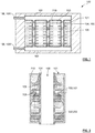
- the figure 1 schematically illustrates a vertical section of a type of SST 100 by MCP 200 of the tube type 104 and calender 101, each tube 104 comprising fins 105 extending radially from a tubular portion 106 of the tube 104, and illustrates its complex architecture.
- the figure 2 shows a vertical section of a tank 101 of SST with tubes 104 and calender 101 when the SST 100 is in a partially discharged state and more particularly illustrates the propensity of the MCP 200 to hang on the heat exchange surfaces, and in particular the fins 105 of the tubes 104, as it solidifies.
- a first of these consists in locating the separation front 203 between the liquid 201 and solid 202 phases of the MCP 200, this separation front 203 being in particular present for an intermediate state of charge of the SST 100.
- the state of charge of the an SST 100 can effectively be measured from a volume value of the liquid phase 201 and the calculation of this value can be envisaged by determining the position of the separation front 203 in the tank 101 comprising a given amount of MCP 200
- the particular architecture of the SST 100 by MCP 200, as well as the propensity of the MCP 200 to hang on the heat exchange surfaces as it solidifies generates a complex arrangement of the separation front 203.
- the arrangement of sensors arranged at different heights of the tank 101 and configured to indicate the presence of a liquid phase 201 or solid 202 is a solution that has been considered.
- the use of different types of sensors has been considered by the University of Brandenburg, whose work has led to the following conclusions. Firstly, the temperature sensors are not suitable because the phase change of the MCP 200 takes place without a change in temperature. The use of sensors measuring the difference in conductivity of the medium is also not convincing because these sensors are not sensitive enough. Finally, the use of sensors evaluating the optical properties of adjacent MCP 200 volume has been retained as the best way to evaluate the state of MCP 200 at one point.
- the intended application case consists of an SST 100 by MCP 200 comprising a simple panel filled with MCP 200 and intended to cover the walls of a building to increase its thermal inertia; this type of SST 100 does not therefore include an embedded exchanger 104 in the MCP 200.
- a measurement of the charge rate ⁇ through an energy balance can still be considered.
- One of the ways to know the state of charge of an SST 100 is actually to record its operating history. For this purpose, the quantity of energy injected or sampled at the SST 100 is measured using a flowmeter and temperature sensors placed in the circuit 108 of the coolant 109 at the inlet 1081 and at the exit 1082 of the circuit 108. knowing the initial state of charge of the SST, when it is put into service, one can theoretically know its state of charge following successive operations of charge and discharge.
- this technique has many disadvantages. First, in order to be able to determine the actual operating history of the SST 100, the heat losses at the outer surfaces of the tank 101 must be finely simulated or measured and taken into account. Then, and in all cases, the accuracy of the estimation of the load ratio ⁇ will deteriorate over time by the accumulation of errors. Finally, such a measurement device requires a lot of electronic elements of acquisition, memory and calculations, making it expensive and unreliable.
- Another technique for measuring the load ratio ⁇ of a SST 100 by MCP is to measure the pressure variation in the sky 210 of the tank 101.
- the sky 210 of a tank 101 corresponds to a dead volume located in its upper part; it is generally composed of an inert gas in order to avoid possible interactions between the MCP 200 and the air which could degrade the properties of the MCP.
- This measurement technique is based on the fact that the MCP used have a high volume expansion during their melting (often of the order of 10% to 20%).
- a rise in pressure therefore takes place in the sky 210 between a total discharge state of the SST 100 for which the MCP is entirely in its solid phase 202 and a total state of charge of the SST for which the MCP is entirely in its liquid phase 201 It is thus possible to correlate the pressure measured in the sky 210 with the liquid phase fraction 201 of MCP 200 formed and thus to determine the charge rate ⁇ .
- this method has many disadvantages.
- these pressure variations subject the tank 101 to high pressure increases: for example for a tank 3 m high, a sky height 210 of 100 mm and a volume expansion of the MCP 200 of 15%, the pressure in the sky 210 can reach 4 bars.
- This aspect can have a non-negligible impact on the cost of the SST 100.
- the influence of the temperature on the air pressure 210 must also be taken into account because its impact can be non-negligible.
- this technique is, by definition, applicable only to MCP having a sufficient volume variation during the phase change.
- another technique for measuring the state of charge of an SST 100 by MCP 200 may still consist of a measurement of the level of a fluid
- the document WO 2016051377 A1 consists in the addition of a measuring fluid 220 compatible and immiscible with the MCP 200 contained in the reservoir 101.
- This measurement fluid 220 must be less dense than the MCP 200 in the liquid phase 201 to remain in the upper part of the reservoir 101.
- the amount of measurement fluid 220 must be sufficient to ensure that the apparent surface of the measurement fluid at the top of the tank 101 is flat when the SST 100 is fully discharged.
- any increase or decrease in the level of this measurement fluid 220 is caused by the melting / solidification of the MCP 200, because of the volume variation of the MCP between its solid and liquid phases. It is therefore possible to establish a law providing the state of charge of the SST as a function of the level of the apparent surface 221 of the measuring fluid 220, this level being able to be measured by an ad hoc sensor 500 .
- the main disadvantage of this measurement technique is the amount of measurement fluid 220 needed to cover all the MCP 200 regardless of the state of charge of the SST 100.
- the impact on the compactness of the SST is direct and possibly non-negligible .
- this technique is limited, by definition, to MCPs having a sufficient volume expansion during the phase change.
- the object of the invention is to respond, at least in part, to the limitations previously set forth.
- the object of the invention is more particularly to provide an SST by MCP which integrates a device for measuring the load ratio ⁇ of the SST which responds, at least in part, to the limitations previously described.
- the excitation device is configured to induce an excitation of the free-vibration part and the sensor is configured to measure a vibration parameter of the free-vibration part, so that the induced excitation is such that the measured vibration parameter depends on the vibration length L vib of the free part in vibration.
- the measurement of the vibration parameter is representative of the load rate ⁇ of the SST.
- the SST advantageously integrates a measuring device comprising a vibratory organ arranged in the reservoir intended to contain the MCP so that its natural frequencies of vibrations are indicative of a certain amount of MCP in the liquid phase in the reservoir and therefore the rate load ⁇ of the SST.
- vibratory organ is preferably understood to mean a member that potentially has both a free vibration part and a static part. Note that a vibratory organ of piezoelectric nature does not seem to be able to present both a free part in vibration and a static part.
- natural frequency ("naturalfrequency” according to the English terminology) of the vibratory organ 300 or more particularly of its free vibration part 301, the frequency with which the vibration member 300 or its free part in vibration 301 oscillates when it is in free evolution, that is to say without external excitatory force, nor dissipative forces (friction or resistance for example).
- the natural frequency remains relevant because it is the frequency for which the losses are minimal; we can then speak of resonance frequency.
- Several eigen modes of vibration of different ranks can be defined for a given vibration length L vib of a free vibration part 301 of a given vibration member 300. In each own mode corresponds to a natural frequency.
- an eigenfrequency of an eigenmode of rank greater than 1 equals a multiple of the eigenfrequency of the first order eigenmode.
- Transverse excitation or vibration of vibratory member 300 or of its free vibration part 301 is understood to mean an excitation or vibration having a component in at least one direction perpendicular to a length of vibratory member 300 (that is that is to say a direction according to which the vibratory body extends mainly) or of its free part in vibration 301.
- the vibratory member 300 is indeed substantially elongated and has a length greater than its other dimensions, at least so to be able to extend on either side of the separation front 203 by having a free-vibration part 201 able to enter in particular transverse vibration.
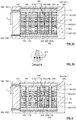
- FIGS. Figures 5a and 6 A transverse vibration of the free vibration portion 301 of a vibratory member 300 is shown in FIGS. Figures 5a and 6 .
- This representation consists more particularly of drawing the free vibration part 301 in three different vibration positions, one centered corresponding to an intermediate vibration position, the other two corresponding to extreme vibration positions to the left and to the right of the position. focused.
- the double arrow separating the extreme vibration positions on the left and on the right illustrates the transverse amplitude of the vibration.
- metal or material "compatible" with the MCP 200 a metal or a material that does not react or that does not degrade, or is not degraded by the MCP 200, for example by corrosion.
- 'high' and 'low' are meant a relative positioning quality of an element of the SST 100 when it is functionally installed, the 'top' being oriented away from the ground and the bottom being oriented towards the ground.
- the MCP 200 changes phase by melting / solidification. It is configured so that at least a portion of a separation front 203 between its liquid phase 201 and its solid phase 202 has, in the tank, a H MCP position , a floor representative of a charge rate ⁇ of the SST 100. .
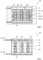
- the figure 5a represents a SST 100 by MCP 200 said tube 104 and calender 101 in which the separation front 203 between liquid phases 201 and 202 of the solid MCP 200 is ideally plan.
- each part of the separation front 203 is identically and perfectly representative of the load ratio ⁇ of the SST.
- the figure 6 represents an SST 100 by MCP 200 with tubes 104 and calender 101 in which the separation front 203 between liquid phases 201 and solid 202 of the MCP 200 is not plane.
- part of the separation front 203 may be more representative of the state of charge of the SST 100 than another part of the separation front 203.
- the part of the front of the separation 203 constituting its zone of inflection between two tubes 104 is more representative of the state of charge of the SST 100 than part of the separation front 203 extending abruptly from a tubular portion 106 of a tube 104 or from the inner walls of the grille 101.
- the vibratory organ 300 has a generally elongate shape. It mainly extends along a direction designated as the principal direction. It extends on either side of the separation front 203 substantially perpendicularly to a plane in which at least the separation front 203 is at least on average.
- the configuration of the vibratory member 300 with respect to the front of the separation 203, and more particularly with respect to the part of the separation front 203, is not necessarily strictly perpendicular; it suffices that the free vibration portion 301 of the vibratory member 300 has a so-called vibration length L vib representative of the H MCP position , the ground of the part of the separation front 203 in the tank 101, this requirement of representativeness that may require, for example, a trigonometric calculation.
- the MCP 200 In a state of total discharge of the SST 100, corresponding to a complete solidification of the MCP 200, the MCP 200 is not present under its liquid phase 201 in the tank 101. In this case, either the free part in vibration 301 of the vibratory member 300 is of zero length, or its length is limited by the corresponding height of the sky 210 in the tank 101.
- the MCP 200 In a state of total charge of the SST 100, corresponding to a completely liquefied state of the MCP 200, the MCP 200 is not present under its solid phase 202 in the tank 101.
- the free-floating portion 301 of the vibratory member 300 is of a length equal to the length of the vibration member 300, considering that the vibratory member 300 is able to vibrate over its entire length when it is not anchored in the solid phase 202 of the MCP 200.
- the vibratory member 300 is fixed by each of its ends 303 and 304 to one of the first and second collector plates 102 and 103 of the SST 100.
- the vibratory member 300 allows a measurement of the load ratio ⁇ of the SST 100 regardless of this charge rate.
- the free vibration portion 301 of the vibratory member 300 is of zero length and it is not possible to excite and therefore to capture its vibration, the length of the free-vibration portion 301 is limited by the height of the sky 210 in the tank 101 and its vibration will be the image of this length, to reveal the total discharge state of the SST 100.
- the SST 100 may be configured such that there always remains a solid phase height 202 of the MCP 200 in the tank 101 regardless of the state of charge of the SST; the vibratory member 300 can then be configured so that one of its ends 330 or 304 is anchored in the solid phase 202 of the MCP 200 whatever the state of charge of the SST 100.
- a device of anchoring such as an anchor
- an anchor can be attached to one end 303 or 304 of the vibratory member 300 so as to improve its anchoring in the solid phase 202 of the MCP 200.
- an anchoring device when attached to the lower end 304 of the vibratory member 300 may have a determined weight to constrain the vibratory organ to a determined tension 300.
- the vibratory member 300 can be fixed by none of its ends 303 and 304 to the tank 101; this may for example be the case when the vibratory member 300 consists of a metal blade simply stuck in the solid phase 202 of the MCP 200.
- the MCP 200 intended to be contained in the tank 101 may comprise at least one of: water, a salt, such as sodium acetate, a salt hydrate, such as nitrate magnesium hexahydrate, a sugar alcohol, such as xylitol, and mixtures thereof, with or without a surfactant additive.
- a mixture may be a eutectic defined as a mixture of two pure bodies which melts and solidifies at a constant temperature; a eutectic behaves in fact like a pure body from the point of view of fusion.
- Such MCP 200 have at least the common point of having a relatively hard solid phase 202 allowing a rigorous anchoring of the vibration member 300.
- a MCP 200 having a solid phase 202 less hard, for example a paraffin was considered, it could be useful to take into account a possible digging of this solid phase 202 by the free vibration portion 301 of the vibratory member 300 in particular according to the excitation exerted on the free part in vibration 301.
- a Such characterization is judged to be within the skill of those skilled in the art, so that the use of a MCP 200 having a less hard solid phase 202 not allowing rigorous anchoring of the vibratory organ is considered to be a matter of the present invention. .
- MCP 200 a wide choice of MCP 200 is possible because the implementation of the invention is not based, contrary to at least some of the techniques of the prior art, on a necessary sufficient variation of volume between phases liquid 201 and solid 202 of the MCP.
- the MCP 200 intended to be contained in the reservoir 101 can effectively have a volume variation when the phase change is less than 20%, less than 10%, or even zero, without this affecting the implementation capacity of the 'invention.
- the excitation device 400 is configured to induce an excitation of the free vibration part 301 of the vibratory organ 300.
- the sensor 500 is configured to measure a vibration parameter of the free vibration portion 301.
- the excitation induced by the excitation device 400 must be such that the measured vibration parameter depends on the vibration length L vib of the free vibration part 301 of the vibratory member 300.
- the vibration parameter depends on the vibration length L vib of the free vibration part 301 of the vibration member 300, that this vibration length L vib is representative of the H MCP position , ground of the part of the separating front 203 in the tank 101 and that this position H MCP, ground is representative of the load ratio ⁇ of the SST 100, the measurement of the vibration parameter is representative of the load ratio ⁇ of the SST 100.
- the invention thus makes it possible to measure the charge rate ⁇ of the SST 100 by the excitation of a vibration member 300 configured so that its vibration is representative of the charge rate ⁇ of the SST 100.
- the specific vibration modes are directly the image of the amount of MCP 200 in the liquid phase 201 in the tank 101; the quantity of MCP 200 in the liquid phase 201 is directly proportional to the charge rate ⁇ of the SST 100.
- the measuring device may furthermore comprise at least one computer 600 to which the measurement of the vibration parameter is transmitted by the sensor, for example in the form of a measurement signal.
- the computer 600 is then configured to deduce from the measurement or the measurement signal at least one natural frequency value f n of vibration of the free vibration part 301 of the vibration member 300, and then to calculate the charge rate ⁇ of the SST 100 at least according to said at least one eigenfrequency value f n .
- the calculation of the load rate ⁇ of the SST 100 can be based on an empirical law determined according to calibration data of the measuring device.
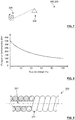
- the empirical law more particularly corresponds to said at least one eigenfrequency value f n at a load rate ⁇ of the SST 100, for example in the manner of the graph represented on the figure 8 .
- the computer 600 may also be connected to a display configured to display the calculated charge rate and possibly other parameters of interest, such as the evolution of the charge rate.
- the computer 600 may further be able to communicate the calculated charge rate to a remote server, for example an energy resource management server of a provider of such resources.
- the measurement signal at the input of a computer 600 may be electrical or digital depending on the sensor 500 used.
- An electronic processing of the measurement signal may be necessary which involves filters and other amplifiers in a known manner.
- the vibration of the free vibration portion 301 of the vibratory member 300 is not necessarily transverse, but may also be longitudinal.
- the excitation device 400 may be configured to punctually or alternatively compress and / or decompress longitudinally the turns of the spring between them.
- a vibration parameter chosen from those introduced above can then be measured which depends on the number of turns of the spring which are not anchored in the solid phase 202 of the MCP 200, in other words which depends on the height of the excitable portion of the spring, this height corresponding to the vibration length L vib of the free vibration portion 301 of the vibratory member 300.
- the vibratory member 300 is a rope 320 and the SST is of the "tube and calender" vertical type, that is to say the front of which separation 203 is intended to extend generally in a horizontal plane.
- this type of SST 100 has a complex architecture making it difficult or impossible to implement known techniques for measuring the load ratio of an SST. If the invention is described below by its implementation in this type of SST 100 complex architecture, it is to show that it is particularly well suited, especially with respect to known techniques. However, the invention is not limited to an application to a SST 100 tube and vertical calender.
- the invention be applied to an SST 100 by MCP 200 said "direct contact".
- the MCP 200 is in direct contact with the coolant.
- hot oil as heat transfer fluid, arrives through a feed tube and gives energy to the MCP 200, causing the melting thereof.
- the oil rises in the upper part of the tank 101 where it is pumped back into the exchanger where it is heated.
- a heat transfer fluid such as water
- the charge of such an SST 100 consists of introducing the hot heat transfer fluid through a first collector plate 102 of the SST 100 and to recover, by a second collector plate 103 of the SST 100, the coolant cooled to yield calories to the MCP 200.
- This dynamic combined with the fact that the liquid phase 201 of the MCP 200 is less dense than its solid phase 202, ensures that the liquid phase 201 of the MCP 200 is still on the top of the tank 101 above the phase 202 solid MCP 200. This avoids an inclusion of PCM in the liquid phase in solid phase MCP, such inclusion being likely to cause significant mechanical stress on the SST 100.
- the separation front 203 is generally in a horizontal plane, but it is envisaged that the separation front may be inclined relative to the horizon, or even globally vertical, the essential being that at least part of the front separation 203 is, because of its position in the tank 101, representative of the state of charge of the SST 100.
- the excitation can be punctual (as on a guitar or a piano) or maintained, if necessary with search for the resonance frequency of the free vibration part 301 of the string 320.
- the measuring device 500 may more particularly be a device for measuring the natural oscillation frequencies of the string 320 in the case of a point excitation or a device for measuring the amplitude of vibration of the string 320 in the case of the sustained excitation and the possible search for the resonance frequency.
- f not vs ⁇ not / ⁇ OV T ⁇ not
- ⁇ n the wavelength associated with the vibration mode of rank n;
- the ideal case discussed above is an example for understanding the operating principle of the invention and the physical laws governing it.
- the first phenomenon concerns the non-flatness of the separation front 203 between the liquid phase 201 and the solid 202 of the MCP 200, this phenomenon being illustrated in particular in FIG. figure 6 .
- the second phenomenon concerns the fact that the liquid phase 201 of the MCP 200, if it can leave free the vibration of the free vibration part 301 of the rope 320, more or less dampens this vibration.
- the separation front 203 has oscillations caused by the inhomogeneity of the thermal conduction in the SST 100, as illustrated by FIG. figure 2 .
- a calibration of the measuring device is again sufficient to bind the natural vibration frequency of the free vibration portion 301 of the cord 320 and the load rate ⁇ of the SST 100.
- Each rope 320 is preferably arranged substantially equidistant from a corresponding set of tubes 104 adjacent to each other.
- the following considerations aim at defining an adimensional parameter allowing to evaluate the impact of the attenuation phenomenon.
- the rope 320 of the measuring device may be a cable which may be manufactured in any metal compatible with the MCP 200 and advantageously in a magnetic or even ferromagnetic material, preferably made of steel. Other materials may be employed as a polyamide, such as nylon for example, if it is compatible with the MCP 200.
- the diameter of the rope is between 0.1 mm and 10 mm, preferably between 0, 5 mm and 5 mm.
- the rope 320 may be fixed on one side of the tank 101, for example by means of a so-called 'hook and ring'system; on the other side of the tank 101, a tensioner 305 can be configured to allow the tensioning of the rope 320.
- the tensioner 305 can be a key (as on a guitar) or a more conventional cable tensioner.
- An abutment 306 on the rope 320 can prevent interference from the vibration modes of the rope 320 by the tensioner 305.
- the tensioning of the rope 320 need not be very precise in the case where a calibration of the measuring device is provided. Moreover, if the tension T of the rope 320 varies too much during its use and thermal stresses, recalibrations can be programmed.
- the tension T of the rope 320 can be calculated when the MCP 200 is completely in its liquid phase 201 by vibrating the string 320 so as to measure in situ its resonance frequency, the other parameters, namely the linear density ⁇ OV and the vibration length L vib , being fixed.
- the tension T of the rope will preferably be between 100 N and 5000 N.
- the voltage / diameter pair is to be adapted case by case, depending on the height of the tank 101, to the frequency ranges that can be measured by the sensor 500.
- the rope 320 may advantageously consist of a core 321 on which a wire or cable 322 is wound. This makes it possible to decouple the sizing parameters that are the elasticity of the string 320 and the linear density ⁇ OV of the string 320.
- the elasticity of the string 320 is determined by the geometry and the composition of the string. the core, while the linear density ⁇ OV of the string 320 can be adjusted by the addition of the wire 322.
- These strings 320 are called "spun ropes".
- the advantage of using spun ropes is in particular to increase the linear density ⁇ OV of the rope 320, without increasing its elasticity or stiffness (which depends on the section of the soul), which can be interesting to facilitate the excitation of the rope 320.
- the excitation of the cord 320 can be done in several ways, and more particularly according to two main principles which consist of a point excitation and a sustained excitation.
- a punctual excitation consists in punctually exiting the string 320 from its equilibrium state, for example over a short length and / or a very short time, in order to initiate in reaction the vibration of the string 320.
- Punctually means “in certain limited cases”: essentially when it is desired to measure the load ratio of the SST 100. More particularly, the rope 320 can be "pinched" (guitar, harp) which corresponds to a small initial displacement followed by a loosening, or "hit” (piano) which corresponds to an initial speed printed on a part of the string 320.
- a plectrum or triangle of flexible plastic can be mounted on a rotating shaft driven by a small motor.
- the tip of the plectrum can be configured to hang the string 320 with each rotation.
- a small hammer (piano type) mounted on an axis is driven by a spring and tap the rope 320.
- a small engine can be used to reset the system and an actuator, for example a solenoid, serves to induce the vibration.
- the objective may be to find the resonant frequency of the string 320, this frequency corresponding to the natural oscillation frequency of the latter.
- the excitation device 400 can then be configured to excite the string 320 by scanning a certain frequency range and the oscillation sensor 500 to determine the maximum amplitude of vibration. corresponding to the natural frequency of vibration of the string 320.
- the excitation is therefore maintained at least the time required to determine the resonance frequency of the string 320; in other words, the excitation is not necessarily maintained all the time, but only when it is desired to measure the load rate of the SST and at least the time required for this measurement.
- the measurement of the oscillations at a point can be done in particular via a magnetic sensor 500 (magnetic microphone type for string instrument) consisting of a magnet surrounded by one or two coils of copper.
- the oscillation of the string 320 disrupts the magnetic field perceived by the coil, which thus transcribes the mechanical periodic signal in electrical form.
- an insert 310 such as a magnet or a magnetic weight, on the rope 320 opposite the magnetic sensor 500; this variant is illustrated on the figure 5b .
- a laser vibrometer or a piezoelectric sensor can be used.
- an acoustic sensor 500 such as a piezoelectric sensor, placed, for example, in the sky 210 of gas of the tank 101, this sky 210 allowing the compensation of the volume variations of the MCP 200, is conceivable.
- a rope or cable 320 of steel 2 mm in diameter is installed in the calender 101, in the middle of a bundle of tubes 104 (between three tubes in the case of an arrangement of the tubes 104 staggered) .
- the linear mass ⁇ OV of the rope is 25 g / m and its tension is 1000 N.
- the excitation system used is that of the rope struck punctually by a small hammer.
- the appearance of the measured oscillation, when the vibration length is 50 cm, shows a main oscillation frequency equal to about 200 Hz. This corresponds to the fundamental vibration frequency, calculated according to the formula: f 1 / ⁇ OV T 2 The vib .
- the interests of the invention are in particular its simplicity of implementation and the possibility of integration with a wide variety of SST, as long as the charge / discharge is made so as to stratify, at least in part, the liquid phases 201 and solid 202 of the MCP 200.
- the liquid phase 201 will be on the top of the tank 101, while in the case of cold storage in ice, it is the liquid water 201 ( denser) which is at the bottom of tank 101 (it will be the opposite for ice storage).
- the frequency measurements are well controlled and very accurate, which allows a high accuracy of the measurement of the load rate ⁇ of the SST 100.
- the invention is also applicable to all the MCP 200 which do not change. , or little, of density by changing state. This is a considerable advantage, since the state of the art consists largely of measuring devices based on this physical phenomenon.
- the low price of SST 100 according to the invention incorporating the measuring device described above makes it all the more attractive.
Landscapes
- Physics & Mathematics (AREA)
- Thermal Sciences (AREA)
- Engineering & Computer Science (AREA)
- Electromagnetism (AREA)
- Mechanical Engineering (AREA)
- General Engineering & Computer Science (AREA)
- Fluid Mechanics (AREA)
- General Physics & Mathematics (AREA)
- Acoustics & Sound (AREA)
- Measuring Volume Flow (AREA)
- Investigating Or Analyzing Materials Using Thermal Means (AREA)
- Measurement Of Levels Of Liquids Or Fluent Solid Materials (AREA)
Priority Applications (1)
| Application Number | Priority Date | Filing Date | Title |
|---|---|---|---|
| PL17177969T PL3264018T3 (pl) | 2016-06-27 | 2017-06-26 | Układ magazynowania ciepła przez mzf zawierający urządzenie do pomiaru parametru reprezentującego szybkość ładowania |
Applications Claiming Priority (1)
| Application Number | Priority Date | Filing Date | Title |
|---|---|---|---|
| FR1655982A FR3053107B1 (fr) | 2016-06-27 | 2016-06-27 | Systeme de stockage thermique par mcp et comprenant un dispositif de mesure d'un parametre representatif du taux de charge |
Publications (2)
| Publication Number | Publication Date |
|---|---|
| EP3264018A1 true EP3264018A1 (de) | 2018-01-03 |
| EP3264018B1 EP3264018B1 (de) | 2021-09-01 |
Family
ID=56855680
Family Applications (1)
| Application Number | Title | Priority Date | Filing Date |
|---|---|---|---|
| EP17177969.7A Active EP3264018B1 (de) | 2016-06-27 | 2017-06-26 | Thermisches pcm-speichersystem, das eine messvorrichtung eines repräsentativen parameters des ladungsniveaus umfasst |
Country Status (4)
| Country | Link |
|---|---|
| EP (1) | EP3264018B1 (de) |
| DK (1) | DK3264018T3 (de) |
| FR (1) | FR3053107B1 (de) |
| PL (1) | PL3264018T3 (de) |
Cited By (5)
| Publication number | Priority date | Publication date | Assignee | Title |
|---|---|---|---|---|
| CN110701938A (zh) * | 2019-10-21 | 2020-01-17 | 浙江大学 | 一种基于旋转磁场的相变储热强化装置及其运行方法 |
| WO2022168023A1 (en) * | 2021-02-07 | 2022-08-11 | Octopus Energy Group Limited | Energy storage arrangement and installations |
| WO2024172663A1 (en) * | 2023-02-15 | 2024-08-22 | Cartesian As | Method and system for controling a state-of-charge of phase change material storage systems |
| EP4435367A1 (de) | 2023-03-22 | 2024-09-25 | Commissariat à l'énergie atomique et aux énergies alternatives | Vorrichtung , um den ladestatus eines wärmespeichers zu ermitteln |
| US12305930B2 (en) | 2021-02-07 | 2025-05-20 | Octopus Energy Heating Limited | Energy storage arrangement and installations |
Families Citing this family (2)
| Publication number | Priority date | Publication date | Assignee | Title |
|---|---|---|---|---|
| CN111121514B (zh) * | 2020-01-07 | 2024-04-30 | 南京工业大学 | 一种移动式相变储热储冷装置 |
| CN111912495A (zh) * | 2020-08-13 | 2020-11-10 | 中水智联(深圳)技术有限公司 | 一种低功耗多功能雷达水位计 |
Citations (7)
| Publication number | Priority date | Publication date | Assignee | Title |
|---|---|---|---|---|
| US3133442A (en) * | 1962-05-23 | 1964-05-19 | Rosemount Eng Co Ltd | Level sensor |
| US3874236A (en) * | 1972-01-22 | 1975-04-01 | Fur Pat Sicherheits Roster G W | Vibration method and apparatus for measuring the level of material in a container |
| US3975958A (en) * | 1973-04-05 | 1976-08-24 | Navaltronic A/S | Apparatus for level measurement of free flowing substances, solid substances or combination of these in tanks, containers, reservoir or the like |
| DE10235581C1 (de) * | 2002-08-03 | 2003-08-21 | Bayerische Motoren Werke Ag | Bestimmung eines Latentwärmespeicher-Ladezustandes, insbesondere in einer Heizungs- und/oder Klimaanlage eines Straßenkraftfahrzeuges |
| WO2012156343A1 (de) | 2011-05-18 | 2012-11-22 | Robert Bosch Gmbh | Verfahren zur bestimmung einer in einem latentwärmespeicher mit einem phasenwechselmaterial gespeicherten wärmeenergie und verfahren zur regelung einer heizung/klimaanlage |
| US20150198441A1 (en) * | 2012-07-17 | 2015-07-16 | Ihc Systems B.V. | Method and device for determining a height of a settled bed in a mixture in a loading space |
| WO2016051377A1 (fr) | 2014-10-01 | 2016-04-07 | Commissariat A L'energie Atomique Et Aux Energies Alternatives | Système et procédé de détermination du taux de charge d'un stockage thermique latent |
Family Cites Families (1)
| Publication number | Priority date | Publication date | Assignee | Title |
|---|---|---|---|---|
| US10634542B2 (en) * | 2016-06-22 | 2020-04-28 | Honeywell International Inc. | Adaptive sync control in radar level sensors |
-
2016
- 2016-06-27 FR FR1655982A patent/FR3053107B1/fr not_active Expired - Fee Related
-
2017
- 2017-06-26 DK DK17177969.7T patent/DK3264018T3/da active
- 2017-06-26 PL PL17177969T patent/PL3264018T3/pl unknown
- 2017-06-26 EP EP17177969.7A patent/EP3264018B1/de active Active
Patent Citations (7)
| Publication number | Priority date | Publication date | Assignee | Title |
|---|---|---|---|---|
| US3133442A (en) * | 1962-05-23 | 1964-05-19 | Rosemount Eng Co Ltd | Level sensor |
| US3874236A (en) * | 1972-01-22 | 1975-04-01 | Fur Pat Sicherheits Roster G W | Vibration method and apparatus for measuring the level of material in a container |
| US3975958A (en) * | 1973-04-05 | 1976-08-24 | Navaltronic A/S | Apparatus for level measurement of free flowing substances, solid substances or combination of these in tanks, containers, reservoir or the like |
| DE10235581C1 (de) * | 2002-08-03 | 2003-08-21 | Bayerische Motoren Werke Ag | Bestimmung eines Latentwärmespeicher-Ladezustandes, insbesondere in einer Heizungs- und/oder Klimaanlage eines Straßenkraftfahrzeuges |
| WO2012156343A1 (de) | 2011-05-18 | 2012-11-22 | Robert Bosch Gmbh | Verfahren zur bestimmung einer in einem latentwärmespeicher mit einem phasenwechselmaterial gespeicherten wärmeenergie und verfahren zur regelung einer heizung/klimaanlage |
| US20150198441A1 (en) * | 2012-07-17 | 2015-07-16 | Ihc Systems B.V. | Method and device for determining a height of a settled bed in a mixture in a loading space |
| WO2016051377A1 (fr) | 2014-10-01 | 2016-04-07 | Commissariat A L'energie Atomique Et Aux Energies Alternatives | Système et procédé de détermination du taux de charge d'un stockage thermique latent |
Cited By (7)
| Publication number | Priority date | Publication date | Assignee | Title |
|---|---|---|---|---|
| CN110701938A (zh) * | 2019-10-21 | 2020-01-17 | 浙江大学 | 一种基于旋转磁场的相变储热强化装置及其运行方法 |
| CN110701938B (zh) * | 2019-10-21 | 2020-08-11 | 浙江大学 | 一种基于旋转磁场的相变储热强化装置及其运行方法 |
| WO2022168023A1 (en) * | 2021-02-07 | 2022-08-11 | Octopus Energy Group Limited | Energy storage arrangement and installations |
| US12305930B2 (en) | 2021-02-07 | 2025-05-20 | Octopus Energy Heating Limited | Energy storage arrangement and installations |
| WO2024172663A1 (en) * | 2023-02-15 | 2024-08-22 | Cartesian As | Method and system for controling a state-of-charge of phase change material storage systems |
| EP4435367A1 (de) | 2023-03-22 | 2024-09-25 | Commissariat à l'énergie atomique et aux énergies alternatives | Vorrichtung , um den ladestatus eines wärmespeichers zu ermitteln |
| FR3147053A1 (fr) | 2023-03-22 | 2024-09-27 | Commissariat A L'energie Atomique Et Aux Energies Alternatives | Dispositif de détermination d’un taux de charge d’un Système de Stockage Thermique |
Also Published As
| Publication number | Publication date |
|---|---|
| DK3264018T3 (da) | 2021-12-06 |
| PL3264018T3 (pl) | 2022-01-31 |
| EP3264018B1 (de) | 2021-09-01 |
| FR3053107B1 (fr) | 2018-07-27 |
| FR3053107A1 (fr) | 2017-12-29 |
Similar Documents
| Publication | Publication Date | Title |
|---|---|---|
| EP3264018B1 (de) | Thermisches pcm-speichersystem, das eine messvorrichtung eines repräsentativen parameters des ladungsniveaus umfasst | |
| EP0129566B1 (de) | Ultraschallverfahren zum messen von spannungen in dazu geeigneten bolzen oder dgl. | |
| EP2391776B1 (de) | System und verfahren zur überwachung des zustands eines fundaments im boden | |
| FR2897691A1 (fr) | Mesure du vecteur deplacement de particules dans une flute marine remorquee | |
| FR2948145A1 (fr) | Tige de forage et train de tiges de forage correspondant | |
| WO2008101814A1 (fr) | Dispositif de conversion d'énergie mécanique d'impacts en énergie électrique à rendement optimisé | |
| EP2817607B1 (de) | Messkopf für dynamisches penetrometer und messverfahren unter verwendung eines solchen messkopfes | |
| EP3411668B1 (de) | Verfahren zur überwachung des thermomechanischen verhaltens einer tiefseeleitung zum transport von unter hohem druck stehenden flüssigkeiten | |
| EP1454132A1 (de) | Ultraschallvorrichtung zur zerstörungsfreien prüfung von metallurgischen produkten | |
| FR2954498A1 (fr) | Dispositif de controle d'un materiau viscoelastique | |
| FR3018605A1 (fr) | Dispositif d'indication du niveau de remplissage d'un conteneur | |
| EP3669029B1 (de) | Statisches penetrometer zur beurteilung des verflüssigbaren charakters von boden und zugehöriges verfahren | |
| EP3655591B1 (de) | Statisches penetrometer und verfahren zur verwendung | |
| EP3299762B1 (de) | Instrumentiertes strukturelement aus beton | |
| EP3256266B1 (de) | Ultraschallwandler, verfahren zur montage davon und strömungsmesser mit mindestens einem solchen wandler | |
| EP3502751B1 (de) | Modellierungsverfahren eines sedimentbeckens | |
| EP3683360B1 (de) | Statischer penetrometer mit ausgelagertem komprimierbaren system, und verwendung eines solchen penetrometers | |
| WO2011141370A1 (fr) | Procede de determination de taux de vide par spectrometrie de resonance acoustique non lineaire dans un milieu diphasique et application dans un reacteur nucleaire | |
| EP4435367A1 (de) | Vorrichtung , um den ladestatus eines wärmespeichers zu ermitteln | |
| EP1411177B1 (de) | Verfahren und Einrichtung zum Messen der Tragfähigkeit eines in den Boden durch Schwingung eingeführten Objektes | |
| FR2695206A1 (fr) | Procédé pour l'établissement d'un diagnostic d'état d'ouvrages d'art et appareillage pour sa mise en Óoeuvre. | |
| FR3100550A1 (fr) | Procédé d'entretien d'une route équipée d'un système de mesure | |
| FR3108579A1 (fr) | Méthode et dispositif de largage d'un lest en milieu subaquatique. | |
| EP3874251A1 (de) | Verfahren zur messung der elasto-plastischen eigenschaften von erde unter verwendung eines statischen penetrometers | |
| FR2602589A1 (fr) | Procede et dispositif de mesure de masse en apesanteur |
Legal Events
| Date | Code | Title | Description |
|---|---|---|---|
| PUAI | Public reference made under article 153(3) epc to a published international application that has entered the european phase |
Free format text: ORIGINAL CODE: 0009012 |
|
| STAA | Information on the status of an ep patent application or granted ep patent |
Free format text: STATUS: REQUEST FOR EXAMINATION WAS MADE |
|
| 17P | Request for examination filed |
Effective date: 20170626 |
|
| AK | Designated contracting states |
Kind code of ref document: A1 Designated state(s): AL AT BE BG CH CY CZ DE DK EE ES FI FR GB GR HR HU IE IS IT LI LT LU LV MC MK MT NL NO PL PT RO RS SE SI SK SM TR |
|
| AX | Request for extension of the european patent |
Extension state: BA ME |
|
| GRAP | Despatch of communication of intention to grant a patent |
Free format text: ORIGINAL CODE: EPIDOSNIGR1 |
|
| STAA | Information on the status of an ep patent application or granted ep patent |
Free format text: STATUS: GRANT OF PATENT IS INTENDED |
|
| RIC1 | Information provided on ipc code assigned before grant |
Ipc: G01F 23/284 20060101ALI20201002BHEP Ipc: G01F 23/296 20060101ALI20201002BHEP Ipc: F28D 20/02 20060101AFI20201002BHEP |
|
| INTG | Intention to grant announced |
Effective date: 20201103 |
|
| GRAJ | Information related to disapproval of communication of intention to grant by the applicant or resumption of examination proceedings by the epo deleted |
Free format text: ORIGINAL CODE: EPIDOSDIGR1 |
|
| STAA | Information on the status of an ep patent application or granted ep patent |
Free format text: STATUS: REQUEST FOR EXAMINATION WAS MADE |
|
| INTC | Intention to grant announced (deleted) | ||
| GRAP | Despatch of communication of intention to grant a patent |
Free format text: ORIGINAL CODE: EPIDOSNIGR1 |
|
| STAA | Information on the status of an ep patent application or granted ep patent |
Free format text: STATUS: GRANT OF PATENT IS INTENDED |
|
| INTG | Intention to grant announced |
Effective date: 20210423 |
|
| GRAS | Grant fee paid |
Free format text: ORIGINAL CODE: EPIDOSNIGR3 |
|
| GRAA | (expected) grant |
Free format text: ORIGINAL CODE: 0009210 |
|
| STAA | Information on the status of an ep patent application or granted ep patent |
Free format text: STATUS: THE PATENT HAS BEEN GRANTED |
|
| AK | Designated contracting states |
Kind code of ref document: B1 Designated state(s): AL AT BE BG CH CY CZ DE DK EE ES FI FR GB GR HR HU IE IS IT LI LT LU LV MC MK MT NL NO PL PT RO RS SE SI SK SM TR |
|
| REG | Reference to a national code |
Ref country code: GB Ref legal event code: FG4D Free format text: NOT ENGLISH |
|
| REG | Reference to a national code |
Ref country code: CH Ref legal event code: EP Ref country code: AT Ref legal event code: REF Ref document number: 1426651 Country of ref document: AT Kind code of ref document: T Effective date: 20210915 |
|
| REG | Reference to a national code |
Ref country code: DE Ref legal event code: R096 Ref document number: 602017045028 Country of ref document: DE |
|
| REG | Reference to a national code |
Ref country code: IE Ref legal event code: FG4D Free format text: LANGUAGE OF EP DOCUMENT: FRENCH |
|
| REG | Reference to a national code |
Ref country code: FI Ref legal event code: FGE |
|
| REG | Reference to a national code |
Ref country code: DK Ref legal event code: T3 Effective date: 20211201 |
|
| REG | Reference to a national code |
Ref country code: SE Ref legal event code: TRGR |
|
| REG | Reference to a national code |
Ref country code: LT Ref legal event code: MG9D |
|
| REG | Reference to a national code |
Ref country code: NL Ref legal event code: MP Effective date: 20210901 |
|
| PG25 | Lapsed in a contracting state [announced via postgrant information from national office to epo] |
Ref country code: BG Free format text: LAPSE BECAUSE OF FAILURE TO SUBMIT A TRANSLATION OF THE DESCRIPTION OR TO PAY THE FEE WITHIN THE PRESCRIBED TIME-LIMIT Effective date: 20211201 Ref country code: LT Free format text: LAPSE BECAUSE OF FAILURE TO SUBMIT A TRANSLATION OF THE DESCRIPTION OR TO PAY THE FEE WITHIN THE PRESCRIBED TIME-LIMIT Effective date: 20210901 Ref country code: NO Free format text: LAPSE BECAUSE OF FAILURE TO SUBMIT A TRANSLATION OF THE DESCRIPTION OR TO PAY THE FEE WITHIN THE PRESCRIBED TIME-LIMIT Effective date: 20211201 Ref country code: ES Free format text: LAPSE BECAUSE OF FAILURE TO SUBMIT A TRANSLATION OF THE DESCRIPTION OR TO PAY THE FEE WITHIN THE PRESCRIBED TIME-LIMIT Effective date: 20210901 Ref country code: HR Free format text: LAPSE BECAUSE OF FAILURE TO SUBMIT A TRANSLATION OF THE DESCRIPTION OR TO PAY THE FEE WITHIN THE PRESCRIBED TIME-LIMIT Effective date: 20210901 Ref country code: RS Free format text: LAPSE BECAUSE OF FAILURE TO SUBMIT A TRANSLATION OF THE DESCRIPTION OR TO PAY THE FEE WITHIN THE PRESCRIBED TIME-LIMIT Effective date: 20210901 |
|
| REG | Reference to a national code |
Ref country code: AT Ref legal event code: MK05 Ref document number: 1426651 Country of ref document: AT Kind code of ref document: T Effective date: 20210901 |
|
| PG25 | Lapsed in a contracting state [announced via postgrant information from national office to epo] |
Ref country code: LV Free format text: LAPSE BECAUSE OF FAILURE TO SUBMIT A TRANSLATION OF THE DESCRIPTION OR TO PAY THE FEE WITHIN THE PRESCRIBED TIME-LIMIT Effective date: 20210901 Ref country code: GR Free format text: LAPSE BECAUSE OF FAILURE TO SUBMIT A TRANSLATION OF THE DESCRIPTION OR TO PAY THE FEE WITHIN THE PRESCRIBED TIME-LIMIT Effective date: 20211202 |
|
| PG25 | Lapsed in a contracting state [announced via postgrant information from national office to epo] |
Ref country code: AT Free format text: LAPSE BECAUSE OF FAILURE TO SUBMIT A TRANSLATION OF THE DESCRIPTION OR TO PAY THE FEE WITHIN THE PRESCRIBED TIME-LIMIT Effective date: 20210901 |
|
| PG25 | Lapsed in a contracting state [announced via postgrant information from national office to epo] |
Ref country code: IS Free format text: LAPSE BECAUSE OF FAILURE TO SUBMIT A TRANSLATION OF THE DESCRIPTION OR TO PAY THE FEE WITHIN THE PRESCRIBED TIME-LIMIT Effective date: 20220101 Ref country code: SM Free format text: LAPSE BECAUSE OF FAILURE TO SUBMIT A TRANSLATION OF THE DESCRIPTION OR TO PAY THE FEE WITHIN THE PRESCRIBED TIME-LIMIT Effective date: 20210901 Ref country code: SK Free format text: LAPSE BECAUSE OF FAILURE TO SUBMIT A TRANSLATION OF THE DESCRIPTION OR TO PAY THE FEE WITHIN THE PRESCRIBED TIME-LIMIT Effective date: 20210901 Ref country code: RO Free format text: LAPSE BECAUSE OF FAILURE TO SUBMIT A TRANSLATION OF THE DESCRIPTION OR TO PAY THE FEE WITHIN THE PRESCRIBED TIME-LIMIT Effective date: 20210901 Ref country code: PT Free format text: LAPSE BECAUSE OF FAILURE TO SUBMIT A TRANSLATION OF THE DESCRIPTION OR TO PAY THE FEE WITHIN THE PRESCRIBED TIME-LIMIT Effective date: 20220103 Ref country code: NL Free format text: LAPSE BECAUSE OF FAILURE TO SUBMIT A TRANSLATION OF THE DESCRIPTION OR TO PAY THE FEE WITHIN THE PRESCRIBED TIME-LIMIT Effective date: 20210901 Ref country code: EE Free format text: LAPSE BECAUSE OF FAILURE TO SUBMIT A TRANSLATION OF THE DESCRIPTION OR TO PAY THE FEE WITHIN THE PRESCRIBED TIME-LIMIT Effective date: 20210901 Ref country code: CZ Free format text: LAPSE BECAUSE OF FAILURE TO SUBMIT A TRANSLATION OF THE DESCRIPTION OR TO PAY THE FEE WITHIN THE PRESCRIBED TIME-LIMIT Effective date: 20210901 Ref country code: AL Free format text: LAPSE BECAUSE OF FAILURE TO SUBMIT A TRANSLATION OF THE DESCRIPTION OR TO PAY THE FEE WITHIN THE PRESCRIBED TIME-LIMIT Effective date: 20210901 |
|
| REG | Reference to a national code |
Ref country code: DE Ref legal event code: R097 Ref document number: 602017045028 Country of ref document: DE |
|
| PLBE | No opposition filed within time limit |
Free format text: ORIGINAL CODE: 0009261 |
|
| STAA | Information on the status of an ep patent application or granted ep patent |
Free format text: STATUS: NO OPPOSITION FILED WITHIN TIME LIMIT |
|
| 26N | No opposition filed |
Effective date: 20220602 |
|
| PG25 | Lapsed in a contracting state [announced via postgrant information from national office to epo] |
Ref country code: SI Free format text: LAPSE BECAUSE OF FAILURE TO SUBMIT A TRANSLATION OF THE DESCRIPTION OR TO PAY THE FEE WITHIN THE PRESCRIBED TIME-LIMIT Effective date: 20210901 |
|
| PG25 | Lapsed in a contracting state [announced via postgrant information from national office to epo] |
Ref country code: MC Free format text: LAPSE BECAUSE OF FAILURE TO SUBMIT A TRANSLATION OF THE DESCRIPTION OR TO PAY THE FEE WITHIN THE PRESCRIBED TIME-LIMIT Effective date: 20210901 |
|
| REG | Reference to a national code |
Ref country code: CH Ref legal event code: PL |
|
| REG | Reference to a national code |
Ref country code: BE Ref legal event code: MM Effective date: 20220630 |
|
| PG25 | Lapsed in a contracting state [announced via postgrant information from national office to epo] |
Ref country code: LU Free format text: LAPSE BECAUSE OF NON-PAYMENT OF DUE FEES Effective date: 20220626 Ref country code: LI Free format text: LAPSE BECAUSE OF NON-PAYMENT OF DUE FEES Effective date: 20220630 Ref country code: IE Free format text: LAPSE BECAUSE OF NON-PAYMENT OF DUE FEES Effective date: 20220626 Ref country code: CH Free format text: LAPSE BECAUSE OF NON-PAYMENT OF DUE FEES Effective date: 20220630 |
|
| PG25 | Lapsed in a contracting state [announced via postgrant information from national office to epo] |
Ref country code: BE Free format text: LAPSE BECAUSE OF NON-PAYMENT OF DUE FEES Effective date: 20220630 |
|
| PG25 | Lapsed in a contracting state [announced via postgrant information from national office to epo] |
Ref country code: HU Free format text: LAPSE BECAUSE OF FAILURE TO SUBMIT A TRANSLATION OF THE DESCRIPTION OR TO PAY THE FEE WITHIN THE PRESCRIBED TIME-LIMIT; INVALID AB INITIO Effective date: 20170626 |
|
| PG25 | Lapsed in a contracting state [announced via postgrant information from national office to epo] |
Ref country code: MK Free format text: LAPSE BECAUSE OF FAILURE TO SUBMIT A TRANSLATION OF THE DESCRIPTION OR TO PAY THE FEE WITHIN THE PRESCRIBED TIME-LIMIT Effective date: 20210901 Ref country code: CY Free format text: LAPSE BECAUSE OF FAILURE TO SUBMIT A TRANSLATION OF THE DESCRIPTION OR TO PAY THE FEE WITHIN THE PRESCRIBED TIME-LIMIT Effective date: 20210901 |
|
| PG25 | Lapsed in a contracting state [announced via postgrant information from national office to epo] |
Ref country code: TR Free format text: LAPSE BECAUSE OF FAILURE TO SUBMIT A TRANSLATION OF THE DESCRIPTION OR TO PAY THE FEE WITHIN THE PRESCRIBED TIME-LIMIT Effective date: 20210901 |
|
| PG25 | Lapsed in a contracting state [announced via postgrant information from national office to epo] |
Ref country code: MT Free format text: LAPSE BECAUSE OF FAILURE TO SUBMIT A TRANSLATION OF THE DESCRIPTION OR TO PAY THE FEE WITHIN THE PRESCRIBED TIME-LIMIT Effective date: 20210901 |
|
| PGFP | Annual fee paid to national office [announced via postgrant information from national office to epo] |
Ref country code: FI Payment date: 20250617 Year of fee payment: 9 |
|
| PGFP | Annual fee paid to national office [announced via postgrant information from national office to epo] |
Ref country code: PL Payment date: 20250617 Year of fee payment: 9 Ref country code: DE Payment date: 20250618 Year of fee payment: 9 |
|
| PGFP | Annual fee paid to national office [announced via postgrant information from national office to epo] |
Ref country code: GB Payment date: 20250625 Year of fee payment: 9 Ref country code: DK Payment date: 20250618 Year of fee payment: 9 |
|
| PGFP | Annual fee paid to national office [announced via postgrant information from national office to epo] |
Ref country code: FR Payment date: 20250623 Year of fee payment: 9 |
|
| PGFP | Annual fee paid to national office [announced via postgrant information from national office to epo] |
Ref country code: SE Payment date: 20250618 Year of fee payment: 9 |
|
| PGFP | Annual fee paid to national office [announced via postgrant information from national office to epo] |
Ref country code: IT Payment date: 20250630 Year of fee payment: 9 |