EP3265247B1 - Rotordüse für ein hochdruckreinigungsgerät - Google Patents
Rotordüse für ein hochdruckreinigungsgerät Download PDFInfo
- Publication number
- EP3265247B1 EP3265247B1 EP15708480.7A EP15708480A EP3265247B1 EP 3265247 B1 EP3265247 B1 EP 3265247B1 EP 15708480 A EP15708480 A EP 15708480A EP 3265247 B1 EP3265247 B1 EP 3265247B1
- Authority
- EP
- European Patent Office
- Prior art keywords
- housing
- accordance
- rotor nozzle
- nozzle
- liquid
- Prior art date
- Legal status (The legal status is an assumption and is not a legal conclusion. Google has not performed a legal analysis and makes no representation as to the accuracy of the status listed.)
- Active
Links
Images

Classifications
-
- B—PERFORMING OPERATIONS; TRANSPORTING
- B05—SPRAYING OR ATOMISING IN GENERAL; APPLYING FLUENT MATERIALS TO SURFACES, IN GENERAL
- B05B—SPRAYING APPARATUS; ATOMISING APPARATUS; NOZZLES
- B05B3/00—Spraying or sprinkling apparatus with moving outlet elements or moving deflecting elements
- B05B3/02—Spraying or sprinkling apparatus with moving outlet elements or moving deflecting elements with rotating elements
- B05B3/04—Spraying or sprinkling apparatus with moving outlet elements or moving deflecting elements with rotating elements driven by the liquid or other fluent material discharged, e.g. the liquid actuating a motor before passing to the outlet
- B05B3/0417—Spraying or sprinkling apparatus with moving outlet elements or moving deflecting elements with rotating elements driven by the liquid or other fluent material discharged, e.g. the liquid actuating a motor before passing to the outlet comprising a liquid driven rotor, e.g. a turbine
- B05B3/0429—Spraying or sprinkling apparatus with moving outlet elements or moving deflecting elements with rotating elements driven by the liquid or other fluent material discharged, e.g. the liquid actuating a motor before passing to the outlet comprising a liquid driven rotor, e.g. a turbine the rotating outlet elements being directly attached to the rotor or being an integral part thereof
- B05B3/043—Rotor nozzles
-
- B—PERFORMING OPERATIONS; TRANSPORTING
- B08—CLEANING
- B08B—CLEANING IN GENERAL; PREVENTION OF FOULING IN GENERAL
- B08B3/00—Cleaning by methods involving the use or presence of liquid or steam
- B08B3/02—Cleaning by the force of jets or sprays
- B08B3/026—Cleaning by making use of hand-held spray guns; Fluid preparations therefor
Definitions
- the invention relates to a rotor nozzle for a high-pressure cleaning device having the features of the preamble of claim 1.
- a compact liquid jet revolving on a conical surface can be produced, which can be directed, for example, onto a surface to be cleaned.
- the inlet of the housing may be supplied by a high pressure cleaning device pressurized liquid, preferably water.
- a nozzle body which is mounted only on one side of the pan-shaped recess and can move in the housing about its longitudinal axis, moreover.
- the nozzle body has a passageway through which the liquid can pass through the perforated recess of the housing.
- the longitudinal axis of the nozzle body is inclined relative to the longitudinal axis of the housing.
- the nozzle body By virtue of the liquid entering tangentially into the housing, the nozzle body is pressed into the socket-shaped depression, which forms a bearing for the nozzle body, and at the same time the nozzle body is set in rotation about the housing longitudinal axis.
- the exiting liquid jet also describes the desired circular movement, so that when a comparable pressure with dot jet nozzles a relatively large area can be acted upon with liquid.
- the nozzle body has a very high rotational speed about the longitudinal axis of the housing, this can, however, result in the liquid jet emerging from the outlet fanning out and thereby reducing the cleaning effect of the liquid jet occurring on the surface to be cleaned.
- the nozzle body In addition to its orbital movement about the longitudinal axis of the housing, the nozzle body performs a self-rotation about its own longitudinal axis. This self-rotation can also fanning out of the outlet Liquid jet and thus lead to a reduction of the cleaning effect.
- Object of the present invention is to provide a rotor nozzle of the type mentioned in such a way that it is less sensitive to pressure fluctuations of the liquid and has a longer life.
- the insert according to the invention forms flow resistance elements which slow down the circulation movement of the liquid within the housing in the region of the flow resistance elements.
- the insert is arranged downstream of the support surface on which the nozzle body is supported with a contact surface on its circumference.
- the support surface may be configured, for example, circular cylindrical or conical, wherein it has no profiling. In the region of the support surface thus an unhindered circulation movement of the liquid is ensured.
- This has the advantage that the insert element arranged downstream of the support surface and having flow resistance elements does not impair the so-called "startup behavior" of the nozzle body.
- the startup behavior is understood to mean the start of the rotation of the nozzle body about the longitudinal axis of the housing.
- the nozzle body Before the housing is supplied under pressure liquid, the nozzle body is relative to the housing at rest, so he does not perform any rotational movement about the housing longitudinal axis. If the liquid supplied to the interior of the housing via the at least one tangential inlet fluid under pressure, so the nozzle body is reliably rotated, but the speed of the nozzle body should not exceed a maximum speed as far as possible to fanning the emerging from the outlet Liquid jet to avoid. This is ensured by the positioning of the insert downstream of the support surface.
- the provision of the insert part has the additional advantage that the housing must have no profiling on the inside.
- An internal profiling could affect the mechanical stability of the housing.
- the housing may have on its inside a relatively smooth surface, so that there is virtually no risk that form cracks in the housing when it is acted upon by the relatively high pressure of the liquid.
- the housing can be a relatively small material thickness have and yet is characterized by a very high mechanical strength, and the provision of the housing rotatably and axially immovably connectable insert allows positioning in the housing flow resistance elements, by the speed of the nozzle body can be limited by the flow resistance elements slowing down the movement of the liquid act.
- the flow resistance elements of the insert act slowing down on the circulating liquid.
- the rotational speed of the nozzle body can be influenced only indirectly, because the flow resistance elements do not directly exert a frictional force on the nozzle body. It is therefore desirable to design the flow resistance elements such that they act particularly strongly on the liquid.
- the flow resistance elements for impact of liquid in each case projecting into the housing baffle and the baffle is upstream of the liquid a guide surface, wherein the guide surface is oriented obliquely to a radial plane of the housing relative to the longitudinal axis thereof.
- On the baffles may bounce liquid, which is thereby hindered in their movement, and the baffles ensure that the liquid is supplied to the immediately following baffle.
- a significant slowdown of the liquid flow can be achieved.
- the insert has a constant wall thickness along its circumference, at least in the area of the flow resistance elements. This facilitates the shaping of the insert part in an injection molding process.
- the insert part has in such a configuration on its outer side a contour which corresponds to the contour on the inside of the insert part.
- the insert part can be screwed to the housing and has a stop surface, which can be applied in the end position of the insert part to an inner shoulder of the housing.
- the insert can be screwed so far into the housing in such an embodiment of the invention until it rests with its stop surface on an inner shoulder of the housing.
- the insert part comprises an external thread which cooperates with a first internal thread of the housing.
- the external thread of the insert is conveniently located downstream of the flow resistance elements.
- the housing has, upstream of the cup-shaped depression, a complementary internal thread to the external thread of the insert part.
- the screwing of the insert is identical to the flow direction of the liquid within the housing.
- the circulating liquid in the housing about its longitudinal axis exerts a force in the circumferential direction on the flow resistance elements of the insert part. Under the action of this force, the insert is pressed with a stop surface against the inner shoulder of the housing, since the screwing of the insert, that is, the directions of rotation of the external thread of the insert and the first internal thread of the housing with the flow direction of the liquid match.
- the circulating liquid thus ensures a structurally simple manner that the screw connection between the insert and the housing does not accidentally dissolve, but the insert is pressed by the liquid in its end position.
- the first internal thread of the housing is designed to be more continuous.
- the insert part for producing a stable screw connection has to be twisted only slightly relative to the housing.
- the insert part must be rotated by a maximum of 360 ° relative to the housing in order to produce a stable screw connection.
- the insert part has to perform less than one revolution in order to reach an end position.
- the inlet of the housing is supplied with pressurized liquid during use of the rotor nozzle.
- the rotor nozzle can have a connection part which can be connected to the housing for connection to a liquid supply line.
- a connection part for example, a jet pipe can be used, which can be connected to the free end of a pressure hose is, over which the jet pipe can be supplied by a high pressure cleaning device with pressurized liquid.
- connection part is rotatably connected to the housing.
- the connecting part is conveniently screwed to the housing of the rotor nozzle.
- the connection part has an external thread which can be screwed into a second internal thread of the housing.
- direction of rotation of the second internal thread coincides with the direction of rotation of the first internal thread.
- a matching direction of rotation of the two internal threads facilitates the shaping of the housing and allows a particularly cost-effective production.
- the direction of rotation of the second internal thread is opposite to the direction of rotation of the first internal thread.
- the screwing-in direction of the insert part corresponds to the circulating movement of the liquid within the housing.
- the insert is thereby pressed by the liquid in its end position.
- the reaction force of the housing does not lead to a loosening of the screw connection between the housing and the connecting part
- the direction of rotation of the second internal thread is favorably opposite to the direction of rotation of the first internal thread.
- the baffles are at least partially disposed in a radial plane relative to the longitudinal axis of the housing.
- the circulating around the housing longitudinal axis liquid can thereby impinge perpendicular to the baffle at least in a region of the baffle and thereby experience a particularly strong deceleration.
- baffle surface connects continuously to each baffle, that is, the baffle closes seamlessly to the baffle and the baffle follows steadily the baffle.
- the surface normals of the guide and baffles merge into one another continuously.
- the guide surfaces are bent in an advantageous embodiment, at least in regions arcuately.
- the guide surfaces are convexly curved at least in regions outwards, that is, in the direction away from the longitudinal axis of the housing.
- Each guide surface in combination with the baffle surface adjoining the guide surface, advantageously forms a channel-shaped widening of the interior of the housing.
- the trough-shaped extensions extend in the direction of the outlet of the housing.
- channel-shaped extensions are aligned obliquely to the longitudinal axis of the housing.
- the channel-shaped extensions are expediently designed to be open.
- the channel-shaped extensions are closed in an advantageous embodiment of the invention. They may be limited, for example, by an end wall, which forms on the outside a stop surface of the insert part, which can be applied in the end position of the insert part to an inner shoulder of the housing.
- the insert part is given a particularly high mechanical load-bearing capacity and at the same time it is ensured that the insert part is pressed against the inner shoulder of the housing by the pressurized liquid.
- a plurality of guide and baffles in the flow direction of the liquid are arranged alternately one behind the other. In the direction of flow of the liquid thus adjoins each baffle an impact surface and at each baffle is in turn followed by a guide surface.
- each guide surface in combination with the baffle surface adjoining the guide surface forms an S-shaped or sawtooth-shaped contour in a plane aligned perpendicular to the longitudinal axis of the housing. It has been shown that a particularly effective slowdown of the liquid flow can be achieved.
- the guide surface extends in the circumferential direction of the housing conveniently over a larger area than the immediately following impact surface.
- the guide surface extends in the circumferential direction over an area that is at least twice as large as the impact surface following the guide surface.
- the liquid is thereby guided over a relatively large peripheral area in each case on a baffle and then braked at this.
- both the housing and the insert are made in the form of an injection molded part from a plastic material.
- the insert forms a prefabricated unit, which can be easily inserted into the housing and bolted to it.
- the assembly of the rotor nozzle is therefore very simple.
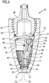
- FIG. 10 an advantageous embodiment of a rotor nozzle according to the invention is shown schematically, which is generally occupied by the reference numeral 10.
- the rotor nozzle 10 has a housing 12 with a housing bottom 14 and a housing cover 16.
- the housing bottom 14 is embodied like a disk and has a plurality of tangential inlets 18. which open into an interior 20 of the housing 12.
- the interior 20 is surrounded by the housing cover 16 and tapers from the tangential inlets 18 to an outlet 22, which is arranged on an end wall 24 of the housing cover 16.
- pressurized liquid can be supplied to the interior 20, which can rotate in the interior 20 about a housing longitudinal axis 26 and emerge from the housing 12 via the outlet 22.
- a bearing is arranged in the interior 20 in the form of a bearing ring 28 which forms a pan-shaped recess 30.
- the bearing ring 28 carries on its outer side a sealing ring 32 and is thereby sealed from the housing cover 16.
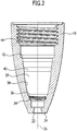
- the housing cover 16 Upstream of the bearing ring 28, the housing cover 16 has a first internal thread 34, which is designed to be more continuous. In the illustrated embodiment, the first internal thread 34 is formed slaughter warmth. Upstream of the first internal thread 34 of the housing cover 16 forms an inner shoulder 36 and upstream of the inner shoulder 36, the housing cover 16 in the form of a conical bearing portion 38 is configured. Upstream of the conical bearing region 38, the housing cover 16 forms a smooth support surface 40, which is conical in the illustrated embodiment. Facing away from the outlet 22, the housing cover 16 at a distance from the support surface 40, a second inner shoulder 42 on which the housing bottom 14 abuts.
- the direction of rotation of the second internal thread 44 may be opposite to the direction of rotation of the first internal thread 34.
- an insert member 46 is screwed, which in the FIGS. 3 and 4 is shown schematically.
- the insert part 46 has an external thread 48, which can be screwed to the first internal thread 34 of the housing cover 16. Upstream of the external thread 48, the insert member 46 forms a plurality of circumferentially uniformly distributed flow resistance elements 50, each having a baffle 52, which is preceded by a guide surface 54.
- the baffles and guide surfaces 52, 54 are arranged in the circumferential direction of the insert part 46 in alternation behind one another and continuously merge into one another.
- baffle and guide surfaces in the illustrated embodiment form an S-shaped contour by both the baffles 52 and the guide surfaces 54 are curved arcuately.
- the baffles 52 have an end portion 56 oriented in a radial plane with respect to the housing longitudinal axis 26. This is going out FIG. 4 clear.
- the extensions are open at their upper end facing the inlets 18 and at their lower end facing the outlet 22 the extensions 55 are closed by an end wall 57.
- the insert part 46 In the area of the flow resistance elements 50, the insert part 46 has a constant material thickness. This facilitates the manufacture of the insert 46 in an injection molding process.
- the insert 46 extends from the first internal thread 34 of the housing cover 16 to an upstream edge 58 of the conical abutment portion 38, so that the circular cylindrical support surface 40 is not affected by the insert 46.
- the insert 46 In the transition region between the external thread 48 and the flow resistance elements 50 forms the insert 46 with the outside of the End wall 57 from a stop surface 60, and the insert member 46 can be screwed with its external thread 48 so far into the first internal thread 34 until the stop surface 60 rests against the first inner shoulder 36 of the housing cover 16.
- a nozzle body 62 can be inserted into the interior 20, which is supported with a crowned end 64 in the cup-shaped recess 30 of the bearing ring 28.
- the nozzle body 62 has a nozzle 66, which forms the crowned end 64, and a nozzle carrier 68, which has a passage 72 extending in the axial direction along a longitudinal axis 70 of the nozzle body 62. In the passage 72, the nozzle 66 is pressed.
- the nozzle 66 has a nozzle channel 74 aligned flush with the passageway 72. In its end region facing away from the nozzle 66, the through-passage 72 widens in stages.
- a centrifugal force-enhancing mass body in the form of a steel ball 76 is held in the area of the nozzle 66.
- the steel ball 76 is followed in the passage 72 in the direction of the nozzle 66, a rectifier 78, which has two mutually perpendicular, parallel to the longitudinal axis 70 of the nozzle body 62 extending and the passageway 72 diametrically interspersed walls.
- the steel ball 76 can be flowed around in the passageway 72 of liquid, so that, after passing through the rectifier 78 and the nozzle 66, it can flow through the bearing ring 28 and the outlet 22 and thereby leave the rotor nozzle 10.
- the nozzle carrier 68 has a circumferentially circumferential annular groove in which an O-ring 86 is held against rotation. Relative to the longitudinal axis 70 of the nozzle body 62, the O-ring 86 protrudes in the radial direction beyond the nozzle carrier 68. It forms a contact surface, with which the nozzle body 62 can be applied to the support surface 40 of the housing cover 16. This is going out FIG. 1 clear.
- the nozzle body 62 extends over at least one third of its total length in the region upstream of the insert part, that is to say in the region between the insert part 46 and the housing bottom 14.
- the channel-shaped extensions 55 are aligned parallel to the longitudinal axis 70 of the nozzle body 62.
- connection part 88 The housing 12 of the rotor nozzle 10 is screwed to a connection part 88, via which the housing 12 of a high-pressure cleaning device under pressure liquid can be supplied.
- connection part 88 has an external thread 90 which can be screwed into the second internal thread 44 of the housing cover 16.
- Liquid supplied via the connection part 88 to the housing 12 passes via the tangential inlets 18 into the interior 20 of the housing 12 and can leave the interior 20 via the through-channel 72, the nozzle channel 74, the bearing ring 28 and the outlet 22.
- the interior space 20 is filled with liquid during operation of the rotor nozzle 10, which is rotated about the housing longitudinal axis 26 by the liquid flowing in via the tangential inlets 18. It thus forms in the interior 20 a rotating about the housing longitudinal axis 26 liquid column.
- the rotating liquid column takes with its spherical front end 64 on the bearing ring 28 supporting the nozzle body 62, so that it also rotates about the housing longitudinal axis 26.
- the nozzle body 62 rests against the circular-cylindrical support surface 40 via the O-ring 86 held non-rotatably on the nozzle body 62.
- the longitudinal axis 70 of the nozzle body 62 is thus inclined to the housing longitudinal axis 26.
- the liquid circulating about the housing longitudinal axis 26 experiences a deceleration due to the baffles 52, on which a part of the circulating liquid impinges. Liquid is in each case supplied via the guide surfaces 54 to a baffle surface 52, so that an effective Deceleration of the liquid can be achieved. Upstream of the insert 46, however, the liquid undergoes no deceleration. This ensures that the nozzle body 62 is reliably offset from the liquid in rotation about the housing longitudinal axis 26. In this area, the nozzle body 62 is located only on one side of the housing longitudinal axis 26, whereas the nozzle body 62 in the region of the insert part 46 and the nozzle 66, the housing longitudinal axis 26 intersects.
- the liquid flowing around the nozzle body 62 could drive the nozzle body 62 in the region in which it intersects the longitudinal axis of the housing 26 to self-rotate about the longitudinal axis 70 of the nozzle body 62.
- the self-rotation of the nozzle body 62 can be kept low.
- the provision of the flow resistance elements 50 achieves a limitation of the rotational speed that the nozzle body 62 has during its rotational movement about the housing longitudinal axis 26.
- the reduction of the self-rotation of the nozzle body 62 and the reduction of the rotational speed of the nozzle body 62 about the housing longitudinal axis 26 ensure that the liquid jet emerging from the housing 12 fans out only slightly.
- the rotor nozzle 10 is therefore characterized by a particularly large cleaning effect.
- the provision of the insert 46 in the form of a prefabricated unit, which can be inserted into the housing cover 16 and screwed with this, has the advantage that the housing cover 16 has a high mechanical strength, since its inner wall both in the conical contact area 38 and in the arranged upstream of the abutment portion 38 may have a smooth surface structure.
- the material thickness of the housing cover 16 can be kept relatively low.
Landscapes
- Nozzles (AREA)
Applications Claiming Priority (1)
| Application Number | Priority Date | Filing Date | Title |
|---|---|---|---|
| PCT/EP2015/054307 WO2016138927A1 (de) | 2015-03-02 | 2015-03-02 | Rotordüse für ein hochdruckreinigungsgerät |
Publications (2)
| Publication Number | Publication Date |
|---|---|
| EP3265247A1 EP3265247A1 (de) | 2018-01-10 |
| EP3265247B1 true EP3265247B1 (de) | 2018-12-26 |
Family
ID=52630353
Family Applications (1)
| Application Number | Title | Priority Date | Filing Date |
|---|---|---|---|
| EP15708480.7A Active EP3265247B1 (de) | 2015-03-02 | 2015-03-02 | Rotordüse für ein hochdruckreinigungsgerät |
Country Status (4)
| Country | Link |
|---|---|
| EP (1) | EP3265247B1 (da) |
| CN (1) | CN107405637B (da) |
| DK (1) | DK3265247T3 (da) |
| WO (1) | WO2016138927A1 (da) |
Families Citing this family (1)
| Publication number | Priority date | Publication date | Assignee | Title |
|---|---|---|---|---|
| DE102022128569A1 (de) | 2022-10-27 | 2024-05-02 | Alfred Kärcher SE & Co. KG | Rotordüse für ein hochdruckreinigungsgerät |
Family Cites Families (6)
| Publication number | Priority date | Publication date | Assignee | Title |
|---|---|---|---|---|
| DE3836053C1 (da) * | 1988-10-22 | 1990-01-11 | Alfred Kaercher Gmbh & Co, 7057 Winnenden, De | |
| DE4419404C2 (de) * | 1994-06-03 | 2001-06-28 | Anton Jaeger | Rotordüse |
| DE19742420A1 (de) * | 1997-09-25 | 1999-04-01 | Anton Jaeger | Rotordüsenkopf |
| DE19832568C2 (de) * | 1998-07-20 | 2003-04-30 | Anton Jaeger | Rotordüse |
| DE102006053625A1 (de) * | 2006-11-14 | 2008-05-15 | Jäger, Anton | Rotordüse |
| DE102009023647A1 (de) * | 2009-05-25 | 2010-12-02 | Alfred Kärcher Gmbh & Co. Kg | Rotordüse für ein Hochdruckreinigungsgerät |
-
2015
- 2015-03-02 CN CN201580077324.8A patent/CN107405637B/zh active Active
- 2015-03-02 DK DK15708480.7T patent/DK3265247T3/da active
- 2015-03-02 WO PCT/EP2015/054307 patent/WO2016138927A1/de not_active Ceased
- 2015-03-02 EP EP15708480.7A patent/EP3265247B1/de active Active
Non-Patent Citations (1)
| Title |
|---|
| None * |
Also Published As
| Publication number | Publication date |
|---|---|
| CN107405637B (zh) | 2019-11-29 |
| DK3265247T3 (da) | 2019-04-01 |
| CN107405637A (zh) | 2017-11-28 |
| EP3265247A1 (de) | 2018-01-10 |
| WO2016138927A1 (de) | 2016-09-09 |
Similar Documents
| Publication | Publication Date | Title |
|---|---|---|
| EP2435190B1 (de) | Rotordüse für ein hochdruckreinigungsgerät | |
| DE4013446C1 (da) | ||
| DE2652584C3 (de) | Sprühvorrichtung zur Erzeugung eines pulsierenden Flüssigkeitsstrahls | |
| DE112012005017B4 (de) | Vorrichtung zum Steuern einer Fluid-Strömung in einem Notfall-Waschsystem, Vorrichtung zum Steuern einer Fluid-Strömung und Waschsystem zum Liefern einer Fluid-Strömung | |
| EP3265235B1 (de) | Rotordüse für ein hochdruckreinigungsgerät | |
| DE102011078857A1 (de) | Sprühdüse und Verfahren zum Erzeugen wenigstens eines rotierenden Sprühstrahls | |
| EP3200928B1 (de) | Düsenanordnung für flüssigkeit | |
| EP2251091B1 (de) | Rotordüse | |
| EP4101546A1 (de) | Topfförmige brausestrahlaustrittsdüse und brause | |
| DE1453730A1 (de) | Radialpumpe | |
| EP2707629B1 (de) | Vorrichtung zum abdichten eines pumpraums einer drehkolbenpumpe, sowie drehkolbenpumpe mit selbiger | |
| EP3265247B1 (de) | Rotordüse für ein hochdruckreinigungsgerät | |
| DE4419404C2 (de) | Rotordüse | |
| DE2434397C2 (de) | Radialturbine | |
| DE4133973C2 (de) | Vorrichtung zum Versprühen eines Flüssigkeitsstrahls mit rotierender Achse auf einer konischen Fläche | |
| DE4220561A1 (de) | Punktstrahl-rotationsduese fuer hochdruckreinigungsgeraete | |
| WO2016138928A1 (de) | Umschaltbare düsenanordnung | |
| EP1437563A2 (de) | Akkumulator für eine Klimaanlage, insbesondere Fahrzeugklimaanlage | |
| DE19820238A1 (de) | Rotordüse | |
| DE202017005877U1 (de) | Düse zum Einbau in eine Reinigungsdüse | |
| EP1502653B1 (de) | Düse zum Besprühen einer Fläche | |
| CH636539A5 (de) | Stroemungsvibrator mit in einem gehaeuse rotierendem schwingkoerper. | |
| EP0762941A1 (de) | Rotordüse für ein hochdruckreinigungsgerät | |
| DE102011077072B3 (de) | Vollstrahldüse | |
| DE102004001222B4 (de) | Düseneinheit und Gargerät mit einer Düseneinheit |
Legal Events
| Date | Code | Title | Description |
|---|---|---|---|
| STAA | Information on the status of an ep patent application or granted ep patent |
Free format text: STATUS: THE INTERNATIONAL PUBLICATION HAS BEEN MADE |
|
| PUAI | Public reference made under article 153(3) epc to a published international application that has entered the european phase |
Free format text: ORIGINAL CODE: 0009012 |
|
| STAA | Information on the status of an ep patent application or granted ep patent |
Free format text: STATUS: REQUEST FOR EXAMINATION WAS MADE |
|
| 17P | Request for examination filed |
Effective date: 20170810 |
|
| AK | Designated contracting states |
Kind code of ref document: A1 Designated state(s): AL AT BE BG CH CY CZ DE DK EE ES FI FR GB GR HR HU IE IS IT LI LT LU LV MC MK MT NL NO PL PT RO RS SE SI SK SM TR |
|
| AX | Request for extension of the european patent |
Extension state: BA ME |
|
| DAV | Request for validation of the european patent (deleted) | ||
| DAX | Request for extension of the european patent (deleted) | ||
| GRAP | Despatch of communication of intention to grant a patent |
Free format text: ORIGINAL CODE: EPIDOSNIGR1 |
|
| STAA | Information on the status of an ep patent application or granted ep patent |
Free format text: STATUS: GRANT OF PATENT IS INTENDED |
|
| INTG | Intention to grant announced |
Effective date: 20180720 |
|
| RAP1 | Party data changed (applicant data changed or rights of an application transferred) |
Owner name: ALFRED KAERCHER SE & CO. KG |
|
| GRAS | Grant fee paid |
Free format text: ORIGINAL CODE: EPIDOSNIGR3 |
|
| GRAA | (expected) grant |
Free format text: ORIGINAL CODE: 0009210 |
|
| STAA | Information on the status of an ep patent application or granted ep patent |
Free format text: STATUS: THE PATENT HAS BEEN GRANTED |
|
| AK | Designated contracting states |
Kind code of ref document: B1 Designated state(s): AL AT BE BG CH CY CZ DE DK EE ES FI FR GB GR HR HU IE IS IT LI LT LU LV MC MK MT NL NO PL PT RO RS SE SI SK SM TR |
|
| REG | Reference to a national code |
Ref country code: GB Ref legal event code: FG4D Free format text: NOT ENGLISH |
|
| REG | Reference to a national code |
Ref country code: CH Ref legal event code: EP |
|
| REG | Reference to a national code |
Ref country code: AT Ref legal event code: REF Ref document number: 1080706 Country of ref document: AT Kind code of ref document: T Effective date: 20190115 |
|
| REG | Reference to a national code |
Ref country code: DE Ref legal event code: R096 Ref document number: 502015007421 Country of ref document: DE |
|
| REG | Reference to a national code |
Ref country code: IE Ref legal event code: FG4D Free format text: LANGUAGE OF EP DOCUMENT: GERMAN |
|
| REG | Reference to a national code |
Ref country code: DK Ref legal event code: T3 Effective date: 20190325 |
|
| PG25 | Lapsed in a contracting state [announced via postgrant information from national office to epo] |
Ref country code: NO Free format text: LAPSE BECAUSE OF FAILURE TO SUBMIT A TRANSLATION OF THE DESCRIPTION OR TO PAY THE FEE WITHIN THE PRESCRIBED TIME-LIMIT Effective date: 20190326 Ref country code: HR Free format text: LAPSE BECAUSE OF FAILURE TO SUBMIT A TRANSLATION OF THE DESCRIPTION OR TO PAY THE FEE WITHIN THE PRESCRIBED TIME-LIMIT Effective date: 20181226 Ref country code: LT Free format text: LAPSE BECAUSE OF FAILURE TO SUBMIT A TRANSLATION OF THE DESCRIPTION OR TO PAY THE FEE WITHIN THE PRESCRIBED TIME-LIMIT Effective date: 20181226 Ref country code: BG Free format text: LAPSE BECAUSE OF FAILURE TO SUBMIT A TRANSLATION OF THE DESCRIPTION OR TO PAY THE FEE WITHIN THE PRESCRIBED TIME-LIMIT Effective date: 20190326 Ref country code: FI Free format text: LAPSE BECAUSE OF FAILURE TO SUBMIT A TRANSLATION OF THE DESCRIPTION OR TO PAY THE FEE WITHIN THE PRESCRIBED TIME-LIMIT Effective date: 20181226 Ref country code: LV Free format text: LAPSE BECAUSE OF FAILURE TO SUBMIT A TRANSLATION OF THE DESCRIPTION OR TO PAY THE FEE WITHIN THE PRESCRIBED TIME-LIMIT Effective date: 20181226 |
|
| REG | Reference to a national code |
Ref country code: NL Ref legal event code: MP Effective date: 20181226 |
|
| REG | Reference to a national code |
Ref country code: LT Ref legal event code: MG4D |
|
| PG25 | Lapsed in a contracting state [announced via postgrant information from national office to epo] |
Ref country code: AL Free format text: LAPSE BECAUSE OF FAILURE TO SUBMIT A TRANSLATION OF THE DESCRIPTION OR TO PAY THE FEE WITHIN THE PRESCRIBED TIME-LIMIT Effective date: 20181226 Ref country code: SE Free format text: LAPSE BECAUSE OF FAILURE TO SUBMIT A TRANSLATION OF THE DESCRIPTION OR TO PAY THE FEE WITHIN THE PRESCRIBED TIME-LIMIT Effective date: 20181226 Ref country code: RS Free format text: LAPSE BECAUSE OF FAILURE TO SUBMIT A TRANSLATION OF THE DESCRIPTION OR TO PAY THE FEE WITHIN THE PRESCRIBED TIME-LIMIT Effective date: 20181226 Ref country code: GR Free format text: LAPSE BECAUSE OF FAILURE TO SUBMIT A TRANSLATION OF THE DESCRIPTION OR TO PAY THE FEE WITHIN THE PRESCRIBED TIME-LIMIT Effective date: 20190327 |
|
| PG25 | Lapsed in a contracting state [announced via postgrant information from national office to epo] |
Ref country code: NL Free format text: LAPSE BECAUSE OF FAILURE TO SUBMIT A TRANSLATION OF THE DESCRIPTION OR TO PAY THE FEE WITHIN THE PRESCRIBED TIME-LIMIT Effective date: 20181226 |
|
| PG25 | Lapsed in a contracting state [announced via postgrant information from national office to epo] |
Ref country code: PL Free format text: LAPSE BECAUSE OF FAILURE TO SUBMIT A TRANSLATION OF THE DESCRIPTION OR TO PAY THE FEE WITHIN THE PRESCRIBED TIME-LIMIT Effective date: 20181226 Ref country code: ES Free format text: LAPSE BECAUSE OF FAILURE TO SUBMIT A TRANSLATION OF THE DESCRIPTION OR TO PAY THE FEE WITHIN THE PRESCRIBED TIME-LIMIT Effective date: 20181226 Ref country code: CZ Free format text: LAPSE BECAUSE OF FAILURE TO SUBMIT A TRANSLATION OF THE DESCRIPTION OR TO PAY THE FEE WITHIN THE PRESCRIBED TIME-LIMIT Effective date: 20181226 Ref country code: PT Free format text: LAPSE BECAUSE OF FAILURE TO SUBMIT A TRANSLATION OF THE DESCRIPTION OR TO PAY THE FEE WITHIN THE PRESCRIBED TIME-LIMIT Effective date: 20190426 |
|
| PG25 | Lapsed in a contracting state [announced via postgrant information from national office to epo] |
Ref country code: RO Free format text: LAPSE BECAUSE OF FAILURE TO SUBMIT A TRANSLATION OF THE DESCRIPTION OR TO PAY THE FEE WITHIN THE PRESCRIBED TIME-LIMIT Effective date: 20181226 Ref country code: IS Free format text: LAPSE BECAUSE OF FAILURE TO SUBMIT A TRANSLATION OF THE DESCRIPTION OR TO PAY THE FEE WITHIN THE PRESCRIBED TIME-LIMIT Effective date: 20190426 Ref country code: EE Free format text: LAPSE BECAUSE OF FAILURE TO SUBMIT A TRANSLATION OF THE DESCRIPTION OR TO PAY THE FEE WITHIN THE PRESCRIBED TIME-LIMIT Effective date: 20181226 Ref country code: SM Free format text: LAPSE BECAUSE OF FAILURE TO SUBMIT A TRANSLATION OF THE DESCRIPTION OR TO PAY THE FEE WITHIN THE PRESCRIBED TIME-LIMIT Effective date: 20181226 Ref country code: SK Free format text: LAPSE BECAUSE OF FAILURE TO SUBMIT A TRANSLATION OF THE DESCRIPTION OR TO PAY THE FEE WITHIN THE PRESCRIBED TIME-LIMIT Effective date: 20181226 |
|
| REG | Reference to a national code |
Ref country code: DE Ref legal event code: R097 Ref document number: 502015007421 Country of ref document: DE |
|
| PG25 | Lapsed in a contracting state [announced via postgrant information from national office to epo] |
Ref country code: MC Free format text: LAPSE BECAUSE OF FAILURE TO SUBMIT A TRANSLATION OF THE DESCRIPTION OR TO PAY THE FEE WITHIN THE PRESCRIBED TIME-LIMIT Effective date: 20181226 |
|
| REG | Reference to a national code |
Ref country code: CH Ref legal event code: PL |
|
| PLBE | No opposition filed within time limit |
Free format text: ORIGINAL CODE: 0009261 |
|
| STAA | Information on the status of an ep patent application or granted ep patent |
Free format text: STATUS: NO OPPOSITION FILED WITHIN TIME LIMIT |
|
| PG25 | Lapsed in a contracting state [announced via postgrant information from national office to epo] |
Ref country code: LU Free format text: LAPSE BECAUSE OF NON-PAYMENT OF DUE FEES Effective date: 20190302 |
|
| 26N | No opposition filed |
Effective date: 20190927 |
|
| REG | Reference to a national code |
Ref country code: BE Ref legal event code: MM Effective date: 20190331 |
|
| PG25 | Lapsed in a contracting state [announced via postgrant information from national office to epo] |
Ref country code: IE Free format text: LAPSE BECAUSE OF NON-PAYMENT OF DUE FEES Effective date: 20190302 Ref country code: CH Free format text: LAPSE BECAUSE OF NON-PAYMENT OF DUE FEES Effective date: 20190331 Ref country code: LI Free format text: LAPSE BECAUSE OF NON-PAYMENT OF DUE FEES Effective date: 20190331 |
|
| PG25 | Lapsed in a contracting state [announced via postgrant information from national office to epo] |
Ref country code: BE Free format text: LAPSE BECAUSE OF NON-PAYMENT OF DUE FEES Effective date: 20190331 Ref country code: SI Free format text: LAPSE BECAUSE OF FAILURE TO SUBMIT A TRANSLATION OF THE DESCRIPTION OR TO PAY THE FEE WITHIN THE PRESCRIBED TIME-LIMIT Effective date: 20181226 |
|
| PG25 | Lapsed in a contracting state [announced via postgrant information from national office to epo] |
Ref country code: TR Free format text: LAPSE BECAUSE OF FAILURE TO SUBMIT A TRANSLATION OF THE DESCRIPTION OR TO PAY THE FEE WITHIN THE PRESCRIBED TIME-LIMIT Effective date: 20181226 |
|
| PGFP | Annual fee paid to national office [announced via postgrant information from national office to epo] |
Ref country code: IT Payment date: 20200221 Year of fee payment: 6 |
|
| PG25 | Lapsed in a contracting state [announced via postgrant information from national office to epo] |
Ref country code: MT Free format text: LAPSE BECAUSE OF FAILURE TO SUBMIT A TRANSLATION OF THE DESCRIPTION OR TO PAY THE FEE WITHIN THE PRESCRIBED TIME-LIMIT Effective date: 20181226 |
|
| REG | Reference to a national code |
Ref country code: AT Ref legal event code: MM01 Ref document number: 1080706 Country of ref document: AT Kind code of ref document: T Effective date: 20200302 |
|
| PG25 | Lapsed in a contracting state [announced via postgrant information from national office to epo] |
Ref country code: CY Free format text: LAPSE BECAUSE OF FAILURE TO SUBMIT A TRANSLATION OF THE DESCRIPTION OR TO PAY THE FEE WITHIN THE PRESCRIBED TIME-LIMIT Effective date: 20181226 |
|
| PG25 | Lapsed in a contracting state [announced via postgrant information from national office to epo] |
Ref country code: HU Free format text: LAPSE BECAUSE OF FAILURE TO SUBMIT A TRANSLATION OF THE DESCRIPTION OR TO PAY THE FEE WITHIN THE PRESCRIBED TIME-LIMIT; INVALID AB INITIO Effective date: 20150302 |
|
| PG25 | Lapsed in a contracting state [announced via postgrant information from national office to epo] |
Ref country code: AT Free format text: LAPSE BECAUSE OF NON-PAYMENT OF DUE FEES Effective date: 20200302 |
|
| PG25 | Lapsed in a contracting state [announced via postgrant information from national office to epo] |
Ref country code: IT Free format text: LAPSE BECAUSE OF NON-PAYMENT OF DUE FEES Effective date: 20210302 |
|
| PG25 | Lapsed in a contracting state [announced via postgrant information from national office to epo] |
Ref country code: MK Free format text: LAPSE BECAUSE OF FAILURE TO SUBMIT A TRANSLATION OF THE DESCRIPTION OR TO PAY THE FEE WITHIN THE PRESCRIBED TIME-LIMIT Effective date: 20181226 |
|
| P01 | Opt-out of the competence of the unified patent court (upc) registered |
Effective date: 20230521 |
|
| PGFP | Annual fee paid to national office [announced via postgrant information from national office to epo] |
Ref country code: GB Payment date: 20260209 Year of fee payment: 12 |
|
| PGFP | Annual fee paid to national office [announced via postgrant information from national office to epo] |
Ref country code: DE Payment date: 20260203 Year of fee payment: 12 Ref country code: DK Payment date: 20260313 Year of fee payment: 12 |
|
| PGFP | Annual fee paid to national office [announced via postgrant information from national office to epo] |
Ref country code: FR Payment date: 20260209 Year of fee payment: 12 |