EP3265774B1 - Dispositif de diagnostic permettant de détecter une excentricité au niveau des roues de véhicules ferroviaires - Google Patents
Dispositif de diagnostic permettant de détecter une excentricité au niveau des roues de véhicules ferroviaires Download PDFInfo
- Publication number
- EP3265774B1 EP3265774B1 EP16707635.5A EP16707635A EP3265774B1 EP 3265774 B1 EP3265774 B1 EP 3265774B1 EP 16707635 A EP16707635 A EP 16707635A EP 3265774 B1 EP3265774 B1 EP 3265774B1
- Authority
- EP
- European Patent Office
- Prior art keywords
- force
- quasi
- diagnostic device
- time
- roundness
- Prior art date
- Legal status (The legal status is an assumption and is not a legal conclusion. Google has not performed a legal analysis and makes no representation as to the accuracy of the status listed.)
- Active
Links
Images

Classifications
-
- G—PHYSICS
- G01—MEASURING; TESTING
- G01M—TESTING STATIC OR DYNAMIC BALANCE OF MACHINES OR STRUCTURES; TESTING OF STRUCTURES OR APPARATUS, NOT OTHERWISE PROVIDED FOR
- G01M17/00—Testing of vehicles
- G01M17/08—Railway vehicles
- G01M17/10—Suspensions, axles or wheels
-
- B—PERFORMING OPERATIONS; TRANSPORTING
- B61—RAILWAYS
- B61K—AUXILIARY EQUIPMENT SPECIALLY ADAPTED FOR RAILWAYS, NOT OTHERWISE PROVIDED FOR
- B61K9/00—Railway vehicle profile gauges; Detecting or indicating overheating of components; Apparatus on locomotives or cars to indicate bad track sections; General design of track recording vehicles
- B61K9/02—Profile gauges, e.g. loading gauges
-
- B—PERFORMING OPERATIONS; TRANSPORTING
- B61—RAILWAYS
- B61K—AUXILIARY EQUIPMENT SPECIALLY ADAPTED FOR RAILWAYS, NOT OTHERWISE PROVIDED FOR
- B61K9/00—Railway vehicle profile gauges; Detecting or indicating overheating of components; Apparatus on locomotives or cars to indicate bad track sections; General design of track recording vehicles
- B61K9/12—Measuring or surveying wheel-rims
-
- B—PERFORMING OPERATIONS; TRANSPORTING
- B61—RAILWAYS
- B61L—GUIDING RAILWAY TRAFFIC; ENSURING THE SAFETY OF RAILWAY TRAFFIC
- B61L1/00—Devices along the route controlled by interaction with the vehicle or train
-
- B—PERFORMING OPERATIONS; TRANSPORTING
- B61—RAILWAYS
- B61L—GUIDING RAILWAY TRAFFIC; ENSURING THE SAFETY OF RAILWAY TRAFFIC
- B61L23/00—Control, warning or like safety means along the route or between vehicles or trains
- B61L23/04—Control, warning or like safety means along the route or between vehicles or trains for monitoring the mechanical state of the route
- B61L23/042—Track changes detection
-
- B—PERFORMING OPERATIONS; TRANSPORTING
- B61—RAILWAYS
- B61L—GUIDING RAILWAY TRAFFIC; ENSURING THE SAFETY OF RAILWAY TRAFFIC
- B61L27/00—Central railway traffic control systems; Trackside control; Communication systems specially adapted therefor
- B61L27/50—Trackside diagnosis or maintenance, e.g. software upgrades
- B61L27/57—Trackside diagnosis or maintenance, e.g. software upgrades for vehicles or trains, e.g. trackside supervision of train conditions
Definitions
- the invention relates to a diagnostic device for detecting an ovality of vehicle wheels of rail vehicles, within a predetermined measurement path, with a plurality of force sensors that are designed / prepared for determining forces acting on them and are connected to an evaluation device, wherein the evaluation designed to determine the out-of-roundness / is prepared.
- Rail vehicles can generate unwanted vibrations when driving by.
- One reason for this is about non-circular wheels with multiple corners or flattenings, which are distributed over the circumference of the wheel.
- Out-of-roundness in rail vehicle wheels, such as wheels of trains, such as passenger trains or freight trains, including their locomotives have a negative impact.
- they lead to unwanted ground vibrations in adjacent buildings, cause high noise emission, reduce the ride comfort and cause damage to the vehicle and the track superstructure. Due to the associated derailment risk, there is a high risk to safety in rail transport.
- Out-of-roundness is to be subsumed under different expressions, such as eccentricity, ovality, the presence of a material order, the presence of flat / flattening, and the presence of polygonisation.
- a special form of ovality is the formation of an ellipse.
- Polygonisation occurs when there are at least three corners on the outside, namely the circumference of the wheel. In part, this polygonization, ie the presence of three or more corners may be present periodically, but may also be unevenly distributed. Out-of-roundness is thus present in one or more deviations from an ideal circular outer contour. These non-circularities deviating from the ideal form of a circle can be categorized in different orders.
- a first-order out-of-roundness should also be understood as eccentricity, whereas an out-of-roundness of the second order also to be understood as ovality.
- An out-of-roundness of the third order is a polygonization, which, depending on the form of the polygonization, can also assume a larger than third order. So far, it is also known to perform roundness measurements with a so-called Rohnrundheitsmessêt.
- the cause of the polygonization is not yet fully understood. However, it is partly due to system natural frequencies of the track and the respective wheelset. Especially when driving at a constant speed over routes with the same type of superstructures, these system frequencies are to be determined. Since it is important to use those wheels whose tread has no spot flattening, uneven contact surfaces or unevenly large Auswalzungen on the rim, it is impermissible in vehicle wheels, especially in the rail vehicle area to detect. It is known that rolling a polygonal wheel over a track produces continuous vibrations. The track with the corresponding substructure and rail vehicle wheel therefore represent a spring-mass system whose oscillation behavior can be analyzed with regard to its amplitudes, period duration, reverberation time, frequency, etc.
- measuring thresholds which define a measuring section with a length of, for example, 1200 mm. It is also known to use four measuring thresholds on a measuring line length of, for example, 2400 mm, just as it is known to use eight measuring thresholds over a measuring line length of, for example, 4,800 mm. The more Measuring thresholds are used and the longer the measuring distance, the more accurate the measurement.
- the EP 1 212 228 B1 a device for detecting Unrund corrosion and flats on vehicle wheels in rail vehicles within a given measuring distance by means of several force sensors for determining the vertical forces acting on the rails, wherein an evaluation device is provided which signals out-of-roundness or flat spots.
- the force transducers are designed as load cells, which are arranged between the rails and stationary cross members or sleepers and that the evaluation device forms an average weight load when crossing the measurement path from the vertical force signals and compares them with the temporal force signal waveform and signaled or displayed when a predetermined deviation is exceeded as out of roundness or flat.
- the method presented there is not independent of the spring stiffnesses defined by the tracks, thresholds, distances of the sleepers, type of subsurface or rigidity of the subsurface. But it should just be largely eliminated by changing the spring stiffness and effects of different damping of the substrate at the installation of the measuring device at least.
- the assured metrological properties should be adhered to and improved over the prior art. Measurement uncertainties should be greatly reduced and reproducibility improved. The long-term stability should also be improved.
- the disadvantages known from the prior art should be reduced or even eliminated.
- the plurality Force sensors comprises, which are provided for determining forces acting on them and are connected to an evaluation device, the evaluation device is designed to integrate a forwarded by the force sensor force signal over time to determine the force impulse.
- the relayed force signal F comprises a quasistatic force component and a dynamic force component.
- the quasi-static force component corresponds to the wheel contact force with an ideal circular wheel.
- the dynamic force component of the forwarded force signal represents the force component that is generated by out-of-roundness of the rail vehicle wheel.
- the evaluation device is accordingly designed to determine the wheel contact force Fm. This can be done either computationally or via a filter. In addition, the evaluation device is designed to correct the forwarded force signal by the wheel contact force Fm and then to integrate the resulting dynamic force component over a time interval. When crossing a rail vehicle over a measuring section, the loads are then detected with force sensors, which are arranged between the thresholds and the running rail. Here you can use an arrangement that is already known as "MULTIRAIL WheelScan".
- the invention is characterized in particular by the fact that the evaluation of the sensor signals is based on a force impulse evaluation method, in contrast to the previously used force amplitude evaluation method.
- this force-impulse evaluation method shows no dependence on the spring rigidity of the components and constructions as well as the background in the force flow of the respective measuring point.
- the power flow are in addition to the long-term stable with respect to their spring construc- tion components such as rail, liner, ribbed plate, sensor, threshold, not long-term stable force transition threshold in the ballast bed and the substructure in the soil.
- Environmental influences such as changes in temperature and humidity, in particular cause the rigidity and damping properties of the substructure and the soil to change. For a better diagnosis of wheel damage such as irregularities, especially flat spots, is now no more only the force amplitude, but in particular the force impact calculated and evaluated.
- the duration of the impact is shorter and the force amplitude is greater.
- the same momentum is reduced over a longer exposure time and thus the force amplitudes are smaller over time.
- the calculated momentum is the same for both.
- F ( t ) is measured with force sensors and thus known, the power surge I be determined by integration over time.
- the evaluation device is designed to integrate the dynamic force component over a time interval that includes the Nachschwingzeit and ends at time t2.
- the time interval over which the dynamic force component integrates begins between the time t0, the occurrence of the shock by the out-of-roundness and the time t1, the first zero crossing of the force signal F corrected by the quasi-static wheel contact force Fm.
- the length of the measuring path corresponds to at least one wheel circumference of a rail vehicle, so that the entire wheel can be detected and tested by the diagnostic device.
- the force sensors are provided in the manner of load cells, weighing bars or weighing discs for detecting forces, such as gravity and / or weight forces.
- forces such as gravity and / or weight forces.
- Particularly robust, reliable and cost-effective modules can then be used.
- a good coordination of costs, longevity and measurement efficiency results when at least one of the force sensors or all force sensors uses / insert one or more strain gauges.
- the force sensors are distributed under a plurality of rail carriers, such as sleepers, for example below 5, 6, 7, 8 or 9 sleepers, in the longitudinal direction of the rails one behind the other.
- the force sensors are distributed in pairs per threshold.
- the force sensors may also be designed as load cells, which are arranged between the rails and stationary cross members or sleepers.
- the load cells may be provided in a recess in the sleepers, the rails being supported on the load cells.
- shear stress sensors are provided in the neutral phase of the rail at the beginning and / or at the end of the measuring section, which serve for force shunt correction and / or as a rail switch.
- the sum of the mean load which represents the weight of the wagon, is additionally formed from the mean wheel contact value of the individual wheels or bogies and from the identified wheels or bogies for a wagon.
- the weight of the wagon is compared with a predetermined maximum value and is signaled as an overload when it is exceeded.
- the center of gravity is determined and with is compared with a predetermined permissible center of gravity range and when crossing the center of gravity this can be signaled as a center of gravity error.
- the invention also relates to a method for determining an out-of-roundness of wheels of rail vehicles within a predetermined measuring path, wherein the force signals are fed to at least one force sensor of an evaluation device, the force signal F, which comprises a quasi-static and a dynamic force component, is processed in the evaluation device, by determining a quasi-static wheel contact force Fm, the force signal F is corrected by the quasi static wheel contact force Fm and the dynamic force component resulting from the difference between F and Fm is integrated over a time interval in order to determine a force impulse,
- the method uses a diagnostic device of the type according to the invention.
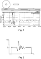
- Fig. 1 is the force waveform when crossing a non-circular Rail vehicle wheel via a measuring point or a measuring section shown.
- the force signal curve on the ordinate in Newton is entered over the time on the abscissa in seconds. It becomes clear from the force signal curve that in the area of out-of-roundness or flattening of the rail vehicle wheel, it initially experiences a decrease relative to the average value resulting from the wheel contact force, whereupon, when the runout strikes the rail, a force peak Fmax follows.
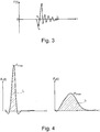
- Fig. 2 is another force waveform on the ordinate over time on the abscissa shown, in which case already the mean value Fm, which corresponds to the quasi-static Radaufstandskraft was determined.
- the vertical force signal is integrated over the illustrated time interval.
- the calculated impulse becomes I corrected by the proportion of the mean value F m , which represents the quasi-static wheel force.
- the correction of the force signal can be done mathematically or by means of a filter.
- Fig. 3 the force waveform Fig. 2 , which has already been adjusted for the mean value Fm or the quasi-static wheel contact force.
- the detection of the force pulse in the force signal curve is calculated and optimized by an evaluation algorithm. Accordingly, the start time t 0 and the end time t 2 of the time interval T are determined via the evaluation algorithm.
- a diagnostic device 1 is shown.
- the diagnostic device 1 is used to detect out-of-roundness in wheels of rail vehicles.
- a rail is indicated by the reference numeral 2.
- a force sensor in the form of a shear stress sensor 3 is connected to an evaluation device 5 via a first electrical line 4.
- a force sensor 8 is present below the rail 2 and within a cross member 6, which is formed as a threshold 7, a force sensor 8 is present.
- the force sensor 8 is formed in the manner of a load cell 9 in this embodiment.
- the force sensor 8 has a strain gauge 12, which is arranged in a blind bore 13, wherein the blind bore 13 is again provided in a deformation body or measuring body 14.
- the force sensor 8 is decisively defined by a force introduction element 15 and a force extraction element 16. For the defined power flow or for the defined guidance of the force from the point of introduction via the strain gauge 12 to the Lastaus effetsstelle by the force sensor 8 horizontal transverse slots 17 and 18 are present.
Landscapes
- Engineering & Computer Science (AREA)
- Mechanical Engineering (AREA)
- Physics & Mathematics (AREA)
- General Physics & Mathematics (AREA)
- Health & Medical Sciences (AREA)
- Biomedical Technology (AREA)
- General Health & Medical Sciences (AREA)
- Automation & Control Theory (AREA)
- Force Measurement Appropriate To Specific Purposes (AREA)
- Radio Transmission System (AREA)
Claims (9)
- Dispositif de diagnostic (1) pour la constatation d'une ovalisation sur des roues de véhicules ferroviaires sur une portion de mesure prédéterminée, avec plusieurs capteurs de force (8), qui sont conçus pour la détermination des forces qui sont exercées sur eux à partir d'une roue de véhicule ferroviaire, et sont reliés avec un dispositif d'analyse (5) conçu- pour traiter un signal de force F transmis par les capteurs de forces (8), qui comprend une composante de force quasi-statique et une composante de force dynamique,- pour déterminer une force d'appui de roue Fm,- et pour corriger le signal de force F de la force d'appui de roue quasi-statique Fm, caractérisé en ce que- le dispositif d'analyse est en outre conçu pour intégrer la composante de force dynamique qui en résulte sur un intervalle de temps afin de déterminer un impact,- l'intervalle de temps commençant entre un moment t0, la survenue de l'impact, et un moment t1, le premier passage à zéro du signal de force F corrigé de la force d'appui quasi-statique Fm.
- Dispositif de diagnostic selon la revendication 1, caractérisé en ce que l'intervalle de temps comprend le temps de décroissance d'une oscillation postérieure et se termine à moment t2.
- Dispositif de diagnostic (1) selon l'une des revendications 1 ou 2, caractérisé en ce que les capteurs de forces (8) sont conçus comme des cellules de pesée (9), des barres ou des disques de pesée.
- Dispositif de diagnostic (1) selon l'une des revendications 1 à 3, caractérisé en ce que le dispositif d'analyse (5) est conçu pour le traitement de l'amplitude de force maximale Fmax.
- Dispositif de diagnostic (1) selon l'une des revendications 1 à 4, caractérisé en ce qu'au moins un des capteurs de forces (8) ou tous les capteurs de forces (8) utilise(nt) une ou plusieurs jauges de contrainte (12).
- Dispositif de diagnostic (1) selon l'une des revendications 1 à 5, caractérisé en ce que la portion de mesure est supérieure ou égale (≥) à la circonférence d'une des roues à mesurer d'un véhicule ferroviaire.
- Dispositif de diagnostic (1) selon l'une des revendications 1 à 6, caractérisé en ce que les capteurs de forces (8) sont disposés entre les rails et les traverses.
- Procédé de détermination d'une ovalisation sur des roues de véhicules ferroviaires sur une portion de mesure prédéterminée, les signaux de forces d'au moins un capteur de force (8) étant entrés dans un dispositif d'analyse (5),- le signal de force F, qui comprend une composante de force quasi-statique et une composante de force dynamique, est traité dans le dispositif d'analyse,- grâce au fait que la force d'appui quasi-statique sur les roues Fm est déterminée,- le signal de force F est corrigé de la force d'appui quasi-statique sur les roues, caractérisé en ce que- la composante de force dynamique résultant de la différence entre F et Fm est intégrée sur un intervalle de temps afin de déterminer un impact,- l'intervalle de temps commençant entre un moment t0, la survenue de l'impact, et un moment t1, le premier passage à zéro du signal de force F corrigé de la force d'appui quasi-statique sur les roues Fm.
- Procédé selon la revendication 8, caractérisé en ce que l'intervalle de temps comprend le temps de décroissance d'une oscillation postérieure.
Applications Claiming Priority (2)
| Application Number | Priority Date | Filing Date | Title |
|---|---|---|---|
| DE102015002517.1A DE102015002517A1 (de) | 2015-03-02 | 2015-03-02 | Diagnoseeinrichtung zur Feststellung einer Unrundheit an Schienenfahrzeugrädern nach einem Kraftstoß-Auswerteverfahren |
| PCT/EP2016/000352 WO2016138986A1 (fr) | 2015-03-02 | 2016-03-01 | Dispositif de diagnostic permettant de détecter une excentricité au niveau des roues de véhicules ferroviaires |
Publications (2)
| Publication Number | Publication Date |
|---|---|
| EP3265774A1 EP3265774A1 (fr) | 2018-01-10 |
| EP3265774B1 true EP3265774B1 (fr) | 2019-01-30 |
Family
ID=55453121
Family Applications (1)
| Application Number | Title | Priority Date | Filing Date |
|---|---|---|---|
| EP16707635.5A Active EP3265774B1 (fr) | 2015-03-02 | 2016-03-01 | Dispositif de diagnostic permettant de détecter une excentricité au niveau des roues de véhicules ferroviaires |
Country Status (6)
| Country | Link |
|---|---|
| US (1) | US10365186B2 (fr) |
| EP (1) | EP3265774B1 (fr) |
| CN (1) | CN107646004B (fr) |
| DE (1) | DE102015002517A1 (fr) |
| ES (1) | ES2718027T3 (fr) |
| WO (1) | WO2016138986A1 (fr) |
Families Citing this family (10)
| Publication number | Priority date | Publication date | Assignee | Title |
|---|---|---|---|---|
| AU2015392675B2 (en) * | 2015-04-28 | 2019-04-11 | Beijing Zongheng Electro-Mechanical Development Co. | Fully continuous ground measurement method and system for wheel rail vertical force |
| ES2887380T3 (es) * | 2017-05-24 | 2021-12-22 | Siemens Mobility GmbH | Control de condición de un elemento de desgaste por uso |
| DE102018117579A1 (de) * | 2018-07-20 | 2020-01-23 | Schenck Process Europe Gmbh | Identifikation eines Schienenfahrzeugrades |
| DE102019114288A1 (de) * | 2019-05-28 | 2020-12-03 | Lausitz Energie Bergbau Ag | Verfahren und Vorrichtung zur Lokalisierung einer singulären Fehlstelle an der Lauffläche eines Rades eines schienengebundenen Fahrzeugs |
| PL3766758T3 (pl) | 2019-07-19 | 2022-10-03 | Frauscher Sensortechnik GmbH | Sposób mierzenia zużycia ciernego szyny oraz system oceniający |
| CN110553861B (zh) * | 2019-08-29 | 2022-03-04 | 朔黄铁路发展有限责任公司 | 列车信息监测方法、装置和设备 |
| CN113776760B (zh) * | 2020-06-09 | 2023-06-27 | 成都运达科技股份有限公司 | 基于整轴振动分析的列车轮对失圆故障监测方法和系统 |
| US11926351B2 (en) | 2020-09-01 | 2024-03-12 | Bnsf Railway Company | Apparatus and method for wear detection of railroad vehicle wheels |
| CN114954562B (zh) * | 2022-04-25 | 2024-07-09 | 中国国家铁路集团有限公司 | 低阶车轮多边形识别方法及装置 |
| AT527202B1 (de) * | 2023-09-21 | 2024-12-15 | Siemens Mobility Austria Gmbh | Verfahren und Vorrichtung zur Entgleisungsdetektion für Schienenfahrzeuge und Schienenfahrzeug |
Family Cites Families (18)
| Publication number | Priority date | Publication date | Assignee | Title |
|---|---|---|---|---|
| US3844513A (en) * | 1970-04-22 | 1974-10-29 | Ericsson Telefon Ab L M | Method and system for detecting wheel flats on rail vehicles |
| DE3309908C2 (de) * | 1982-04-22 | 1987-04-02 | Messerschmitt-Bölkow-Blohm GmbH, 8012 Ottobrunn | Verfahren zur Ermittlung von Flachstellen an Schienenrädern |
| US4679447A (en) * | 1986-01-13 | 1987-07-14 | Amsted Industries Incorporated | Method and apparatus for positioning and testing railroad wheels |
| US5577690A (en) * | 1994-09-15 | 1996-11-26 | Jodon Engineering Associates, Inc. | Microwave measurement of train wheel wear |
| DE19941843A1 (de) * | 1999-09-02 | 2001-03-08 | Schenck Process Gmbh | Vorrichtung zur Feststellung von Unrundheiten und Flachstellen an Rädern bei Schienenfahrzeugen |
| AT410921B (de) * | 2000-10-12 | 2003-08-25 | Siemens Sgp Verkehrstech Gmbh | Verfahren und vorrichtung zur schadenserkennung an rädern eines schienenfahrzeuges |
| DE20317201U1 (de) * | 2003-11-05 | 2004-03-18 | Db Cargo Ag | Vorrichtung zur Ermittlung einer Abweichung eines drehsymmetrischen Körpers von einer vorgegebenen Form aus Messwerten |
| CN101057128A (zh) * | 2004-09-11 | 2007-10-17 | 通用电气公司 | 轨道感测设备和方法 |
| AT503177B1 (de) * | 2005-05-25 | 2008-10-15 | Hottinger Messtechnik Baldwin | Verfahren zur erfassung der radform eines schienenrades |
| DE202006005190U1 (de) | 2006-03-31 | 2006-06-22 | Neuroth, Bernd, Tres Cantos | Anordnung zur Überprüfung der Laufräder von Schienenfahrzeugen |
| DE102009041823A1 (de) * | 2009-09-18 | 2011-03-24 | Knorr-Bremse Systeme für Schienenfahrzeuge GmbH | Verfahren und Vorrichtung zur Überwachung des Fahrverhaltens eines Schienenfahrzeugs |
| FI124881B (fi) * | 2012-02-24 | 2015-03-13 | Tamtron Systems Oy | Parannettu menetelmä ja järjestely kiskolla kulkevan kulkuvälineen ominaisuuksien mittaamiseksi |
| US8818585B2 (en) * | 2012-10-24 | 2014-08-26 | Progress Rail Services Corp | Flat wheel detector with multiple sensors |
| CO7080240A1 (es) * | 2013-04-01 | 2014-10-10 | Univ Eafit | Sistema para detectar defectos en la redondez de las ruedas de un vehiculo ferroviario |
| AT515500A1 (de) * | 2014-03-12 | 2015-09-15 | Siemens Ag Oesterreich | Vorrichtung und Verfahren zur Hinderniserkennung bei Schienenfahrzeugen |
| WO2016030009A1 (fr) * | 2014-08-29 | 2016-03-03 | Schenck Process Gmbh | Dispositif et procédé pour la détermination de caractéristiques géométriques d'un profil de roue sur une roue qui tourne d'un véhicule ferroviaire |
| US10124819B2 (en) * | 2016-08-08 | 2018-11-13 | General Electric Company | Wheel deformity warning system |
| WO2018220469A1 (fr) * | 2017-05-29 | 2018-12-06 | Alireza Alemi | Surveillance d'état de roue |
-
2015
- 2015-03-02 DE DE102015002517.1A patent/DE102015002517A1/de not_active Withdrawn
-
2016
- 2016-03-01 ES ES16707635T patent/ES2718027T3/es active Active
- 2016-03-01 WO PCT/EP2016/000352 patent/WO2016138986A1/fr not_active Ceased
- 2016-03-01 EP EP16707635.5A patent/EP3265774B1/fr active Active
- 2016-03-01 CN CN201680012916.6A patent/CN107646004B/zh active Active
-
2017
- 2017-09-05 US US15/695,258 patent/US10365186B2/en active Active
Non-Patent Citations (1)
| Title |
|---|
| None * |
Also Published As
| Publication number | Publication date |
|---|---|
| WO2016138986A1 (fr) | 2016-09-09 |
| DE102015002517A1 (de) | 2016-09-08 |
| ES2718027T3 (es) | 2019-06-27 |
| US10365186B2 (en) | 2019-07-30 |
| CN107646004B (zh) | 2020-03-27 |
| US20170363518A1 (en) | 2017-12-21 |
| EP3265774A1 (fr) | 2018-01-10 |
| CN107646004A (zh) | 2018-01-30 |
Similar Documents
| Publication | Publication Date | Title |
|---|---|---|
| EP3265774B1 (fr) | Dispositif de diagnostic permettant de détecter une excentricité au niveau des roues de véhicules ferroviaires | |
| DE2606149C2 (de) | Anordnung an einem Fahrzeug zum Messen und Aufzeichnen geometrischer Daten verlegter Eisenbahnschienen | |
| EP2850401B1 (fr) | Module capteur d'un système wim et procédé de mesure | |
| EP0282615A1 (fr) | Dispositif de détection de roues détériorées | |
| EP1212228B1 (fr) | Dispositif permettant de detecter des excentricites et des zones plates sur des roues de vehicule sur rails | |
| AT500769B1 (de) | Verfahren zur erfassung von kräften von elastischen verformungen zumindest einer schiene und eines oberbaues | |
| DE102019210884B4 (de) | Messanordnung sowie Verfahren zur Ermittlung einer Distanz zwischen einem an einem achsmontierten Getriebe eines schienengebundenen Fahrzeugs angeordneten Abstandssensor und einer Messnullfläche außerhalb des Getriebes im laufenden Betrieb | |
| EP3374246B1 (fr) | Procédé et dispositif de détection de déraillement commandée par comparaison | |
| DE3309908C2 (de) | Verfahren zur Ermittlung von Flachstellen an Schienenrädern | |
| EP1592595B1 (fr) | Parcours de mesure permettant de determiner differentes grandeurs physiques de vehicules ferroviaires | |
| DE102019114288A1 (de) | Verfahren und Vorrichtung zur Lokalisierung einer singulären Fehlstelle an der Lauffläche eines Rades eines schienengebundenen Fahrzeugs | |
| EP1278673B1 (fr) | Procede de surveillance de caracteristiques de deplacement d'un vehicule sur rail | |
| DE10304008B4 (de) | Vorrichtung zur Messung der Schienenbelastung | |
| WO2017197423A1 (fr) | Procédé et dispositif de surveillance d'au moins un composant de voie posé dans la construction de chemin de fer | |
| EP1847819B1 (fr) | Section de mesure sur un rail | |
| DE10347812B4 (de) | Kraftmessvorrichtung zur Erfassung der Schienenbelastung | |
| DE10241320A1 (de) | Vorrichtung zur Erfassung von Veränderungen an Eisenbahnrädern im Betriebseinsatz | |
| AT502735B1 (de) | Verfahren zur ermittlung des raddurchmessers von sich längs zweier paralleler fahrschienen bewegenden rädern von schienenfahrzeugen | |
| DE3226740A1 (de) | Anordnung zum messen der radlasten schnellfahrender schienenfahrzeuge und verfahren sowie vorrichtung zum bestimmen der radlasten mit einer solchen anordnung | |
| EP3823876B1 (fr) | Procédé et système de reconnaissance d'une roue de véhicule ferroviaire | |
| EP4098991B1 (fr) | Dispositif et procédé pour déterminer les faux-ronds d'une roue d'un véhicule sur rails | |
| DE10009156C1 (de) | Verfahren und Vorrichtung zum Ermitteln der Eigenschaften der Radfederung eines Drehgestells von Schienenfahrzeugen | |
| DE102015113357B4 (de) | Verfahren zur Analyse und/oder Überwachung von Brücken sowie ein entsprechendes System | |
| DE102004032407B3 (de) | Akustische Bewertung von Gleisen | |
| DE102022100785A1 (de) | Verfahren und Vorrichtung zur Bestimmung der Länge L einer Flachstelle an der Lauffläche eines Rades eines schienengebundenen Fahrzeugs |
Legal Events
| Date | Code | Title | Description |
|---|---|---|---|
| STAA | Information on the status of an ep patent application or granted ep patent |
Free format text: STATUS: THE INTERNATIONAL PUBLICATION HAS BEEN MADE |
|
| PUAI | Public reference made under article 153(3) epc to a published international application that has entered the european phase |
Free format text: ORIGINAL CODE: 0009012 |
|
| STAA | Information on the status of an ep patent application or granted ep patent |
Free format text: STATUS: REQUEST FOR EXAMINATION WAS MADE |
|
| 17P | Request for examination filed |
Effective date: 20170823 |
|
| AK | Designated contracting states |
Kind code of ref document: A1 Designated state(s): AL AT BE BG CH CY CZ DE DK EE ES FI FR GB GR HR HU IE IS IT LI LT LU LV MC MK MT NL NO PL PT RO RS SE SI SK SM TR |
|
| AX | Request for extension of the european patent |
Extension state: BA ME |
|
| DAV | Request for validation of the european patent (deleted) | ||
| DAX | Request for extension of the european patent (deleted) | ||
| RAP1 | Party data changed (applicant data changed or rights of an application transferred) |
Owner name: SCHENCK PROCESS EUROPE GMBH |
|
| GRAP | Despatch of communication of intention to grant a patent |
Free format text: ORIGINAL CODE: EPIDOSNIGR1 |
|
| STAA | Information on the status of an ep patent application or granted ep patent |
Free format text: STATUS: GRANT OF PATENT IS INTENDED |
|
| RIC1 | Information provided on ipc code assigned before grant |
Ipc: G01M 17/10 20060101AFI20180919BHEP Ipc: B61L 23/04 20060101ALI20180919BHEP Ipc: B61L 1/00 20060101ALI20180919BHEP Ipc: B61K 9/12 20060101ALI20180919BHEP |
|
| INTG | Intention to grant announced |
Effective date: 20181002 |
|
| GRAS | Grant fee paid |
Free format text: ORIGINAL CODE: EPIDOSNIGR3 |
|
| GRAA | (expected) grant |
Free format text: ORIGINAL CODE: 0009210 |
|
| STAA | Information on the status of an ep patent application or granted ep patent |
Free format text: STATUS: THE PATENT HAS BEEN GRANTED |
|
| RAP1 | Party data changed (applicant data changed or rights of an application transferred) |
Owner name: SCHENCK PROCESS EUROPE GMBH |
|
| AK | Designated contracting states |
Kind code of ref document: B1 Designated state(s): AL AT BE BG CH CY CZ DE DK EE ES FI FR GB GR HR HU IE IS IT LI LT LU LV MC MK MT NL NO PL PT RO RS SE SI SK SM TR |
|
| REG | Reference to a national code |
Ref country code: GB Ref legal event code: FG4D Free format text: NOT ENGLISH |
|
| REG | Reference to a national code |
Ref country code: CH Ref legal event code: EP |
|
| REG | Reference to a national code |
Ref country code: AT Ref legal event code: REF Ref document number: 1093675 Country of ref document: AT Kind code of ref document: T Effective date: 20190215 |
|
| REG | Reference to a national code |
Ref country code: IE Ref legal event code: FG4D Free format text: LANGUAGE OF EP DOCUMENT: GERMAN |
|
| REG | Reference to a national code |
Ref country code: DE Ref legal event code: R096 Ref document number: 502016003286 Country of ref document: DE |
|
| REG | Reference to a national code |
Ref country code: SE Ref legal event code: TRGR |
|
| REG | Reference to a national code |
Ref country code: LT Ref legal event code: MG4D |
|
| REG | Reference to a national code |
Ref country code: NL Ref legal event code: MP Effective date: 20190130 |
|
| REG | Reference to a national code |
Ref country code: ES Ref legal event code: FG2A Ref document number: 2718027 Country of ref document: ES Kind code of ref document: T3 Effective date: 20190627 |
|
| PG25 | Lapsed in a contracting state [announced via postgrant information from national office to epo] |
Ref country code: NO Free format text: LAPSE BECAUSE OF FAILURE TO SUBMIT A TRANSLATION OF THE DESCRIPTION OR TO PAY THE FEE WITHIN THE PRESCRIBED TIME-LIMIT Effective date: 20190430 Ref country code: PT Free format text: LAPSE BECAUSE OF FAILURE TO SUBMIT A TRANSLATION OF THE DESCRIPTION OR TO PAY THE FEE WITHIN THE PRESCRIBED TIME-LIMIT Effective date: 20190530 Ref country code: PL Free format text: LAPSE BECAUSE OF FAILURE TO SUBMIT A TRANSLATION OF THE DESCRIPTION OR TO PAY THE FEE WITHIN THE PRESCRIBED TIME-LIMIT Effective date: 20190130 Ref country code: NL Free format text: LAPSE BECAUSE OF FAILURE TO SUBMIT A TRANSLATION OF THE DESCRIPTION OR TO PAY THE FEE WITHIN THE PRESCRIBED TIME-LIMIT Effective date: 20190130 Ref country code: LT Free format text: LAPSE BECAUSE OF FAILURE TO SUBMIT A TRANSLATION OF THE DESCRIPTION OR TO PAY THE FEE WITHIN THE PRESCRIBED TIME-LIMIT Effective date: 20190130 |
|
| PG25 | Lapsed in a contracting state [announced via postgrant information from national office to epo] |
Ref country code: LV Free format text: LAPSE BECAUSE OF FAILURE TO SUBMIT A TRANSLATION OF THE DESCRIPTION OR TO PAY THE FEE WITHIN THE PRESCRIBED TIME-LIMIT Effective date: 20190130 Ref country code: HR Free format text: LAPSE BECAUSE OF FAILURE TO SUBMIT A TRANSLATION OF THE DESCRIPTION OR TO PAY THE FEE WITHIN THE PRESCRIBED TIME-LIMIT Effective date: 20190130 Ref country code: GR Free format text: LAPSE BECAUSE OF FAILURE TO SUBMIT A TRANSLATION OF THE DESCRIPTION OR TO PAY THE FEE WITHIN THE PRESCRIBED TIME-LIMIT Effective date: 20190501 Ref country code: IS Free format text: LAPSE BECAUSE OF FAILURE TO SUBMIT A TRANSLATION OF THE DESCRIPTION OR TO PAY THE FEE WITHIN THE PRESCRIBED TIME-LIMIT Effective date: 20190530 Ref country code: BG Free format text: LAPSE BECAUSE OF FAILURE TO SUBMIT A TRANSLATION OF THE DESCRIPTION OR TO PAY THE FEE WITHIN THE PRESCRIBED TIME-LIMIT Effective date: 20190430 Ref country code: RS Free format text: LAPSE BECAUSE OF FAILURE TO SUBMIT A TRANSLATION OF THE DESCRIPTION OR TO PAY THE FEE WITHIN THE PRESCRIBED TIME-LIMIT Effective date: 20190130 |
|
| PG25 | Lapsed in a contracting state [announced via postgrant information from national office to epo] |
Ref country code: DK Free format text: LAPSE BECAUSE OF FAILURE TO SUBMIT A TRANSLATION OF THE DESCRIPTION OR TO PAY THE FEE WITHIN THE PRESCRIBED TIME-LIMIT Effective date: 20190130 Ref country code: IT Free format text: LAPSE BECAUSE OF FAILURE TO SUBMIT A TRANSLATION OF THE DESCRIPTION OR TO PAY THE FEE WITHIN THE PRESCRIBED TIME-LIMIT Effective date: 20190130 Ref country code: EE Free format text: LAPSE BECAUSE OF FAILURE TO SUBMIT A TRANSLATION OF THE DESCRIPTION OR TO PAY THE FEE WITHIN THE PRESCRIBED TIME-LIMIT Effective date: 20190130 Ref country code: AL Free format text: LAPSE BECAUSE OF FAILURE TO SUBMIT A TRANSLATION OF THE DESCRIPTION OR TO PAY THE FEE WITHIN THE PRESCRIBED TIME-LIMIT Effective date: 20190130 Ref country code: RO Free format text: LAPSE BECAUSE OF FAILURE TO SUBMIT A TRANSLATION OF THE DESCRIPTION OR TO PAY THE FEE WITHIN THE PRESCRIBED TIME-LIMIT Effective date: 20190130 Ref country code: CZ Free format text: LAPSE BECAUSE OF FAILURE TO SUBMIT A TRANSLATION OF THE DESCRIPTION OR TO PAY THE FEE WITHIN THE PRESCRIBED TIME-LIMIT Effective date: 20190130 Ref country code: MC Free format text: LAPSE BECAUSE OF FAILURE TO SUBMIT A TRANSLATION OF THE DESCRIPTION OR TO PAY THE FEE WITHIN THE PRESCRIBED TIME-LIMIT Effective date: 20190130 Ref country code: SK Free format text: LAPSE BECAUSE OF FAILURE TO SUBMIT A TRANSLATION OF THE DESCRIPTION OR TO PAY THE FEE WITHIN THE PRESCRIBED TIME-LIMIT Effective date: 20190130 |
|
| REG | Reference to a national code |
Ref country code: CH Ref legal event code: PL Ref country code: DE Ref legal event code: R097 Ref document number: 502016003286 Country of ref document: DE |
|
| PG25 | Lapsed in a contracting state [announced via postgrant information from national office to epo] |
Ref country code: LU Free format text: LAPSE BECAUSE OF NON-PAYMENT OF DUE FEES Effective date: 20190301 Ref country code: SM Free format text: LAPSE BECAUSE OF FAILURE TO SUBMIT A TRANSLATION OF THE DESCRIPTION OR TO PAY THE FEE WITHIN THE PRESCRIBED TIME-LIMIT Effective date: 20190130 |
|
| PLBE | No opposition filed within time limit |
Free format text: ORIGINAL CODE: 0009261 |
|
| STAA | Information on the status of an ep patent application or granted ep patent |
Free format text: STATUS: NO OPPOSITION FILED WITHIN TIME LIMIT |
|
| REG | Reference to a national code |
Ref country code: BE Ref legal event code: MM Effective date: 20190331 |
|
| 26N | No opposition filed |
Effective date: 20191031 |
|
| PG25 | Lapsed in a contracting state [announced via postgrant information from national office to epo] |
Ref country code: IE Free format text: LAPSE BECAUSE OF NON-PAYMENT OF DUE FEES Effective date: 20190301 Ref country code: CH Free format text: LAPSE BECAUSE OF NON-PAYMENT OF DUE FEES Effective date: 20190331 Ref country code: LI Free format text: LAPSE BECAUSE OF NON-PAYMENT OF DUE FEES Effective date: 20190331 |
|
| PG25 | Lapsed in a contracting state [announced via postgrant information from national office to epo] |
Ref country code: FR Free format text: LAPSE BECAUSE OF NON-PAYMENT OF DUE FEES Effective date: 20190330 Ref country code: SI Free format text: LAPSE BECAUSE OF FAILURE TO SUBMIT A TRANSLATION OF THE DESCRIPTION OR TO PAY THE FEE WITHIN THE PRESCRIBED TIME-LIMIT Effective date: 20190130 Ref country code: BE Free format text: LAPSE BECAUSE OF NON-PAYMENT OF DUE FEES Effective date: 20190331 |
|
| PG25 | Lapsed in a contracting state [announced via postgrant information from national office to epo] |
Ref country code: TR Free format text: LAPSE BECAUSE OF FAILURE TO SUBMIT A TRANSLATION OF THE DESCRIPTION OR TO PAY THE FEE WITHIN THE PRESCRIBED TIME-LIMIT Effective date: 20190130 |
|
| PG25 | Lapsed in a contracting state [announced via postgrant information from national office to epo] |
Ref country code: MT Free format text: LAPSE BECAUSE OF FAILURE TO SUBMIT A TRANSLATION OF THE DESCRIPTION OR TO PAY THE FEE WITHIN THE PRESCRIBED TIME-LIMIT Effective date: 20190130 |
|
| PG25 | Lapsed in a contracting state [announced via postgrant information from national office to epo] |
Ref country code: CY Free format text: LAPSE BECAUSE OF FAILURE TO SUBMIT A TRANSLATION OF THE DESCRIPTION OR TO PAY THE FEE WITHIN THE PRESCRIBED TIME-LIMIT Effective date: 20190130 |
|
| PG25 | Lapsed in a contracting state [announced via postgrant information from national office to epo] |
Ref country code: HU Free format text: LAPSE BECAUSE OF FAILURE TO SUBMIT A TRANSLATION OF THE DESCRIPTION OR TO PAY THE FEE WITHIN THE PRESCRIBED TIME-LIMIT; INVALID AB INITIO Effective date: 20160301 |
|
| PG25 | Lapsed in a contracting state [announced via postgrant information from national office to epo] |
Ref country code: MK Free format text: LAPSE BECAUSE OF FAILURE TO SUBMIT A TRANSLATION OF THE DESCRIPTION OR TO PAY THE FEE WITHIN THE PRESCRIBED TIME-LIMIT Effective date: 20190130 |
|
| REG | Reference to a national code |
Ref country code: DE Ref legal event code: R081 Ref document number: 502016003286 Country of ref document: DE Owner name: QLAR EUROPE GMBH, DE Free format text: FORMER OWNER: SCHENCK PROCESS EUROPE GMBH, 64293 DARMSTADT, DE |
|
| REG | Reference to a national code |
Ref country code: AT Ref legal event code: HC Ref document number: 1093675 Country of ref document: AT Kind code of ref document: T Owner name: QLAR EUROPE GMBH, DE Effective date: 20250407 |
|
| PGFP | Annual fee paid to national office [announced via postgrant information from national office to epo] |
Ref country code: ES Payment date: 20250429 Year of fee payment: 10 |
|
| REG | Reference to a national code |
Ref country code: ES Ref legal event code: PC2A Owner name: QLAR EUROPE GMBH Effective date: 20251105 |
|
| PGFP | Annual fee paid to national office [announced via postgrant information from national office to epo] |
Ref country code: SE Payment date: 20260319 Year of fee payment: 11 |
|
| PGFP | Annual fee paid to national office [announced via postgrant information from national office to epo] |
Ref country code: GB Payment date: 20260324 Year of fee payment: 11 |
|
| PGFP | Annual fee paid to national office [announced via postgrant information from national office to epo] |
Ref country code: DE Payment date: 20260319 Year of fee payment: 11 |
|
| PGFP | Annual fee paid to national office [announced via postgrant information from national office to epo] |
Ref country code: AT Payment date: 20260320 Year of fee payment: 11 |
|
| PGFP | Annual fee paid to national office [announced via postgrant information from national office to epo] |
Ref country code: FI Payment date: 20260323 Year of fee payment: 11 |