EP4098991B1 - Dispositif et procédé pour déterminer les faux-ronds d'une roue d'un véhicule sur rails - Google Patents
Dispositif et procédé pour déterminer les faux-ronds d'une roue d'un véhicule sur rails Download PDFInfo
- Publication number
- EP4098991B1 EP4098991B1 EP22176488.9A EP22176488A EP4098991B1 EP 4098991 B1 EP4098991 B1 EP 4098991B1 EP 22176488 A EP22176488 A EP 22176488A EP 4098991 B1 EP4098991 B1 EP 4098991B1
- Authority
- EP
- European Patent Office
- Prior art keywords
- measuring
- subsection
- length
- wheel
- over
- Prior art date
- Legal status (The legal status is an assumption and is not a legal conclusion. Google has not performed a legal analysis and makes no representation as to the accuracy of the status listed.)
- Active
Links
Images


Classifications
-
- G—PHYSICS
- G01—MEASURING; TESTING
- G01M—TESTING STATIC OR DYNAMIC BALANCE OF MACHINES OR STRUCTURES; TESTING OF STRUCTURES OR APPARATUS, NOT OTHERWISE PROVIDED FOR
- G01M17/00—Testing of vehicles
- G01M17/08—Railway vehicles
- G01M17/10—Suspensions, axles or wheels
-
- B—PERFORMING OPERATIONS; TRANSPORTING
- B61—RAILWAYS
- B61K—AUXILIARY EQUIPMENT SPECIALLY ADAPTED FOR RAILWAYS, NOT OTHERWISE PROVIDED FOR
- B61K9/00—Railway vehicle profile gauges; Detecting or indicating overheating of components; Apparatus on locomotives or cars to indicate bad track sections; General design of track recording vehicles
- B61K9/12—Measuring or surveying wheel-rims
-
- B—PERFORMING OPERATIONS; TRANSPORTING
- B61—RAILWAYS
- B61L—GUIDING RAILWAY TRAFFIC; ENSURING THE SAFETY OF RAILWAY TRAFFIC
- B61L1/00—Devices along the route controlled by interaction with the vehicle or train
- B61L1/02—Electric devices associated with track, e.g. rail contacts
- B61L1/06—Electric devices associated with track, e.g. rail contacts actuated by deformation of rail; actuated by vibration in rail
-
- B—PERFORMING OPERATIONS; TRANSPORTING
- B61—RAILWAYS
- B61L—GUIDING RAILWAY TRAFFIC; ENSURING THE SAFETY OF RAILWAY TRAFFIC
- B61L25/00—Recording or indicating positions or identities of vehicles or trains or setting of track apparatus
- B61L25/02—Indicating or recording positions or identities of vehicles or trains
- B61L25/021—Measuring and recording of train speed
-
- B—PERFORMING OPERATIONS; TRANSPORTING
- B61—RAILWAYS
- B61L—GUIDING RAILWAY TRAFFIC; ENSURING THE SAFETY OF RAILWAY TRAFFIC
- B61L27/00—Central railway traffic control systems; Trackside control; Communication systems specially adapted therefor
- B61L27/50—Trackside diagnosis or maintenance, e.g. software upgrades
- B61L27/57—Trackside diagnosis or maintenance, e.g. software upgrades for vehicles or trains, e.g. trackside supervision of train conditions
Definitions
- the invention relates to a device for determining the out-of-roundness of a wheel of a rail-bound vehicle according to the preamble of claim 1 or 2 and to a method for determining the out-of-roundness of a wheel of a rail-bound vehicle according to claim 10 or 11.
- the running surfaces of the wheels of rail-bound vehicles are of crucial importance with regard to ride comfort and the safety of rail transport, since the static and dynamic forces that occur during travel are introduced into the rails via the running surfaces and wheel flanges.
- the geometry of the running surfaces corresponds to a slightly conical surface that runs concentrically around the wheel axle and with which the wheels roll on the rails.
- the running surfaces thus form the rotating part of the wheel-rail contact.
- Deviations from the ideal circular shape for example due to uneven wear, material and manufacturing defects and the like, are referred to as out-of-roundness. These include, among other things, singular out-of-roundness such as flat spots, flattening and material build-up as well as periodic out-of-roundness such as eccentricities, ovalities and polygonizations.
- out-of-roundness increases the dynamic proportion of the forces exerted by the wheel on the rail, with the risk of damage to the rail vehicle and rail track.
- the associated safety risks, as well as noise emissions and vibrations of the ground are undesirable.
- EP 0 282 615 A1 describes an arrangement for detecting wheel damage using acceleration sensors that extend linearly along a rail.
- the linear acceleration sensors record the acceleration transmitted from the wheel to the rail at any point along their length.
- the individual measurement signals obtained in this way are subjected to an evaluation procedure in order to obtain information about the extent of wheel damage.
- Characteristics that provide information about the type and severity of the wheel damage are filtered out of the measurement signal curve using suitable frequency filter stages and/or an FFT analysis.
- the disadvantage of this method is that it only produces a rough measurement result.
- the EP 1 883 565 A1 a method for detecting the wheel shapes of rail vehicle wheels using a measuring section that is made up of a series of measuring elements attached to the rails.
- the wheel loads acting on the measuring elements generate electrical signals proportional to the force, which are fed to an electronic evaluation device for evaluation.
- an information array is generated from the signals derived from the measuring elements, which correspond to the movement of the rail in the vertical direction and preferably also in the transverse direction, which maps at least one wheel circumference.
- the information array is made up of several information cells, whereby the respective signal components of different information cells can be continuously added together and relevant signal components are evaluated.
- a method and a device for detecting roundness errors on the wheels of rail vehicles are known.
- a section of track resting on sleepers is equipped with piezoelectric acceleration sensors which record the amplitude of the track vibrations caused by the wheels when the track section is passed over.
- the acceleration sensors are arranged between the sleepers of the track section, the length of which is at least equal to the circumference of the wheels.
- Inductive sensors at the ends of the track section are used for synchronization and to determine the wheel speed.
- the signals recorded by the acceleration sensors are digitized and filtered in a vibration range with maximum damping so that errors can be detected by comparing them with reference signal curves, their type can be determined more precisely and the wheels affected by errors can be identified.
- the DE 10 2019 114 288 A1 discloses a method and a device for locating a singular defect on the running surface of a wheel of a rail-bound vehicle when crossing a rail designed as a measuring section in the X direction, wherein the contact force F of the wheel is continuously recorded over the length L of the measuring section with the aid of a force measuring device.
- a distance measuring device records the lateral distance of the wheel to the rail at at least one defined position within the measuring section.
- the defect is then detected by evaluating the course of the wheel contact force F in an electronic evaluation unit, wherein the position of the wheel-rail contact on the running surface of the wheel is determined at the time the defect occurs and on the basis of the recorded lateral distance.
- the invention is based on the object of specifying a device and a method with which the out-of-roundness of a wheel of a rail-bound vehicle can be determined reliably and with high accuracy, taking economic aspects into account.
- the invention is based on the basic idea of using the measured values of the wheel contact forces obtained when a rail vehicle travels over a measuring section not only to determine the weight of the rail vehicle, but also to evaluate them with regard to possible wheel runouts.
- the prerequisite for a complete recording of the runouts is that the measuring section extends over at least one wheel circumference.
- knowledge of the actual wheel circumference (actual wheel circumference) of a wheel to be tested is essential. It turns out to be problematic that the actual wheel circumference differs from the original wheel circumference (nominal wheel circumference) due to gradual wear.
- it is therefore intended to determine the actual wheel circumference when rolling over the measuring section or the time period ⁇ t that corresponds to the rolling of the actual wheel circumference U actual on the measuring section.
- the invention has recognized that it is sufficient for determining the actual wheel circumference or the time period ⁇ t if characteristic features are repeated in the course of the measurement signal, whereby the measurement signal can also come from sensors other than the force transducers. If a sufficiently large agreement indicates a repetition of the measurement signal course, it is assumed according to the invention that the section of the measurement signal course between a characteristic feature and its repetition corresponds to the actual wheel circumference.
- the actual wheel circumference U determined in this way or the time period ⁇ t determined in this way is, according to the invention, used to evaluate the wheel circumference determined with force transducers. force signal curve, whereby the section of the force signal curve determined for the evaluation corresponds to the length of the actual wheel circumference or the time window ⁇ t.
- a first advantage resulting from this is the possibility of using sensors that require relatively little effort to purchase and/or install.
- sensors suitable for the invention such as acceleration sensors, can be mounted directly on the rails in the area between the sleepers without affecting the bearing of the rail on the sleepers.
- the installation of a device according to the invention on a track is therefore possible with relatively little equipment effort and in a short time, which leads to an extremely advantageous cost-benefit ratio.
- devices and methods according to the invention are not only suitable for the construction of new measuring lines, but also excellently for retrofitting existing measuring lines, the functionality of which is expanded in this way.
- the length of a measuring section according to the invention is selected in such a way that from the repetition of significant features in the measurement signal curve, it can be concluded with sufficient probability that the repetitive features are due to the same circumferential section of the wheel.
- the length of a measuring section according to the invention is greater than the simple actual wheel circumference U .
- the length of the measuring section corresponds to at least 1.2 times the nominal wheel circumference U nom .
- the significance of the measured values can be further increased if the length of the measuring section is chosen to be larger. In this sense, a length of the measuring section which corresponds to at least 1.5 times the nominal wheel circumference U nom or even at least twice the nominal wheel circumference U nom is particularly preferred by the invention.
- the correspondence of recurring significant features in the measurement signal curve is determined by autocorrelation, wherein the measurement signal curve is examined for relationships between temporally spaced measurement signal curve sections.
- the force signal curve of the first partial measuring section and the acceleration signal curve of the second partial measuring section are recorded independently of one another.
- the measurement data from both partial measuring sections are thus directly included in the evaluation, which promotes the accuracy and reliability of the evaluation.
- first partial measuring section and the second partial measuring section can follow one another in the direction of travel, i.e. to be spatially separated from one another, with the second partial measuring section following the first partial measuring section or vice versa.
- the length of the measuring section is therefore obtained by adding the first partial measuring section and the second partial measuring section, and the force signal curve and acceleration signal curve are generated one after the other.
- first partial measuring section and the second partial measuring section may partially or completely overlap in the direction of travel.
- the force signals and acceleration signals are at least partially recorded simultaneously.
- Such an embodiment opens up the possibility of making the measuring section extremely compact, which is particularly advantageous when space is limited and thus extends the range of application of a device according to the invention to cramped conditions.
- the force signal curve of the first partial measuring section and the acceleration signal curve of a remaining measuring section, which together form the second partial measuring section are combined with one another.
- it is provided to transform the acceleration signal curve into a force signal curve or the force signal curve into an acceleration signal curve. Since the force transducers are functionally part of both the first partial measuring section and the second partial measuring section, they have a dual function, so that in this embodiment the effort for the measuring device and its installation can be reduced to an absolute minimum.
- the force sensors used are preferably load beams, load cells or weighing discs, which are arranged under the rail, usually in the sleeper or between the rail and the ground.
- several force sensors are preferably provided, one after the other in the direction of travel, the distance between them preferably being between 300 mm and 1000 mm.
- the maximum distance between the force transducers and acceleration transducers is advantageously based on the sleeper distance, with the maximum distance between the force transducers and/or acceleration transducers corresponding to twice the sleeper distance, preferably to one sleeper distance.
- the force transducers are arranged below the rail, preferably between the rail and the sleeper or the rail and the subsoil.
- the acceleration transducers are arranged directly on the rail. Accordingly, the advantage of using acceleration transducers is that no intervention in the substructure of the rails or in the track bed is necessary. This results in considerable time and cost savings.
- a measuring section according to the invention has at least one transverse force sensor per rail, which is, for example, integrated into the rail and records the shear stresses caused by a wheel load in the rail.
- Suitable transverse force sensors are, for example, strain gauges or measuring eyes.
- the transverse force signal generated by a transverse force sensor can be used to determine exactly the time determine the moment at which a wheel rolls over the lateral force sensor. Such a signal can be used, for example, as a trigger for starting and/or stopping a measuring process and/or for axle and vehicle identification.
- the duration of the crossing from the first transverse force sensor to the second transverse force sensor can be determined on the basis of the times assigned to the two transverse force signals and the driving speed v of the rail vehicle can be determined.
- the driving speed v calculated in this way is advantageously used directly to determine the out-of-roundness of a wheel.
- a preferred embodiment of the invention provides for several transverse force sensors to be provided in each rail within a partial measuring section, one after the other in the direction of travel, which divide the partial measuring section into several sections. This has the further advantage, among other things, that changes in the driving speed v within the measuring section can be recorded and taken into account when determining the actual wheel circumference U actual , which allows a higher level of accuracy to be achieved when evaluating the measuring signals.
- the transverse force sensors have a mutual distance that corresponds to one or two times the threshold distance. This embodiment ensures that only one wheel of a rail vehicle is located between two adjacent transverse force sensors of a partial measuring section; a signal measured in this section can therefore be clearly assigned to this wheel. The evaluation of the measurement signals is thus simplified, which not least contributes to a high level of accuracy and quality of the evaluation result.
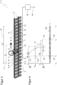
- Fig. 1 shows a first embodiment of a device according to the invention with a measuring section 1 for evaluating the wheel contact force F and acceleration a during the passage of a rail-bound vehicle over the measuring section 1.
- the illustration shows a section of a rail track 2 designed as a measuring section 1 with two rails 3 running parallel to one another, which are supported by a large number of sleepers 4. The mutual distance between the sleepers 4 is in a range of approximately 600 mm to 700 mm.
- the rail track 2 is traveled by a rail-bound vehicle at a speed v, for example a passenger or freight car, for which only the wheels 5 of a wheelset axle (not shown in more detail) are shown as representatives.
- the direction of travel of the rail-bound vehicle is designated by x
- the wheel contact force exerted by a wheel 5 on a rail 3 is designated by F.
- the measuring section 1 comprises a first partial measuring section 1.1 for recording the wheel contact force F and a second partial measuring section 1.2 for recording the acceleration a with which the wheels 5 act on the rails 3 while a rail-bound vehicle is traveling over the measuring section 1.
- the two partial measuring sections 1.1 and 1.2 follow one another in the direction of travel x, with the second partial measuring section 1.2 seamlessly connecting to the first partial measuring section 1.1 in the direction of travel x.
- a reverse order and/or a spatial distance between the two partial measuring sections 1.1 and 1.2 are also within the scope of the invention.
- the first partial measuring section 1.1 extends over a length L1 which corresponds at least to the simple nominal wheel circumference U nom of the wheels 5 of the vehicles travelling on the rail track 2. With a standard wheel diameter of approximately 1250 mm, this results in a length of at least 2925 mm.
- a first measuring device for recording the wheel contact force F exerted by a wheel 5 on the rail 3 is integrated into the rail track 2.
- the first measuring device comprises two transverse force sensors 6, 7 arranged on the rail 3, one of which is installed at the beginning and the other at the end of the first partial measuring section 1.1. These are, for example, measuring eyes or strain gauges that record the shear stresses induced by the wheels 5 in the rails 3 in analog form and convert them into digital measuring signals.
- the transverse force sensors 6, 7 serve on the one hand to correct the force shunt in order to compensate for interference from adjacent rail sections.
- the transverse force sensors 6, 7 can be used as switches for the start and end of the measuring process of the first measuring device and/or for axle detection and vehicle identification.
- the lateral force transducers 6, 7 are used to determine the driving speed v in the area of the first partial measuring section 1.1, which can be determined on the basis of the known distance of the lateral force transducer 6 from the lateral force transducer 7 in the direction of travel x and the known time period T, which corresponds to the difference between the rollover times t 0 and t X (see Fig. 2a ).
- force sensors 8 are provided in the area of the first partial measuring section 1.1 for detecting the wheel contact force F, for example weighing beams, load cells or weighing discs.
- force sensors 8 are provided in succession in the direction of travel x, the mutual distance of which in the direction of travel x corresponds to a maximum of twice the threshold distance, preferably the single threshold distance.
- each of the two rails 3 rests on force sensors 8, which in turn are mounted on successive sleepers 4.
- the second partial measuring section 1.2 has a length L2 which is greater than the length L1 and which corresponds to at least 1.2 times the nominal wheel circumference U nom of the wheels 5 of the vehicles travelling on the rail track 2, preferably 1.5 times, most preferably 2 times. With a standard wheel diameter of approximately 1250 mm, this results in a length L2 of at least 4710 mm, preferably at least 5888 mm, most preferably 7850 mm.
- the device according to the invention has a second measuring device for detecting the acceleration a exerted by a wheel 5 on the rail 3, which is also integrated into the rail track 2.
- the second measuring device also comprises transverse force sensors 9, 10 installed at the beginning and end of the rail 3, whereby in the present first embodiment the first transverse force sensor 9 in the direction of travel x corresponds to the second transverse force sensor 7 of the first partial measuring section 1.1, i.e. has a dual function.
- the transverse force sensors 9, 10 correspond to those of the first partial measuring section 1.1, so that the statements there apply accordingly, in particular with regard to the possibility of a force shunt correction and determination of the travel speed v in the area of the second partial measuring section 1.2.
- acceleration sensors 11 are provided in the area of the second partial measuring section 1.2 to record the acceleration a.
- the acceleration sensors 11 are each attached between two sleepers 4 on the underside of the rails 3, which results in a mutual distance between the acceleration sensors 11 in the direction of travel x, which corresponds to the single sleeper distance, but can also correspond to twice the sleeper distance.
- the acceleration sensors 11 record the acceleration value or the acceleration signal of the rail at the point where the sensor is located.
- the transverse force sensors 6, 7, 9, 10, force sensors 8 for the wheel contact force F and acceleration sensors 11 are connected by data lines 12 to an electronic evaluation unit 13 in which the data storage and data processing takes place.
- the data from a measurement process is transmitted to a higher-level central location via radio or another data line 14.
- Fig. 2a shows the temporal progression of the force signal F measured by force transducers 8 during the crossing of the partial measuring section 1.1.
- the measuring process carried out by the first measuring device begins at time t 0 , defined by the wheel 5 rolling over the transverse force transducer 6, and ends at time t X , at which the wheel 5 rolls over the transverse force transducer 7 and thus leaves the area of the first partial measuring section 1.1.
- the time period T between times t 0 and t x thus corresponds to the duration of the crossing of the first partial measuring section 1.1, the length L1 of which corresponds at least to the simple nominal wheel circumference U nom and is therefore greater than the actual wheel circumference U .
- the amplitude of the force signal F fluctuates, depending on the quality of the running surface of the wheel 5, to a greater or lesser extent around a value that corresponds to the static load component F stat . 15 designates a force maximum or minimum that deviates significantly from the fluctuation range and, due to its gradient and height, indicates an out-of-roundness on the running surface of the wheel 5.
- Fig. 2b the time course of the acceleration signal a measured by the acceleration sensors 11 during the crossing of the second partial measuring section 1.2 is shown.
- the rolling over of the transverse force sensor 9 by the wheel 5 corresponds to the time t 0 at which the measuring process by the second measuring device in the area of the second partial measuring section 1.2 begins.
- the rolling over of the transverse force sensor 10 by the same wheel 5 defines the time t X , which simultaneously represents the end of the measuring process.
- the time period T lying between the times t 0 and t x in turn corresponds to the duration of the crossing of the second partial measuring section 1.2, the length L2 of which is greater than the length L1 of the first partial measuring section and in the present case corresponds to twice the nominal wheel circumference U nom .
- the spatial distance between the transverse force transducers 9, 10 corresponds to the length L2 of the second partial measuring section 1.2
- the driving speed v of the rail vehicle in the second partial measuring section 1.2 results in accordance with the above statements.
- the amplitude of the acceleration signal a fluctuates more or less strongly around the value zero depending on the quality of the running surface of the wheel 5.
- the force maximum or force minimum 15 of the force signal curve F(t) ( Fig. 2a ) corresponds to an acceleration maximum 16 in the acceleration signal curve a(t) that deviates significantly from the fluctuation range and is due to the same out-of-roundness on the running surface of the wheel 5.
- the time of the first occurrence of the acceleration maximum 16 is in Fig. 2b designated with t 1. Due to the specified length L2 of the second partial measuring section 1.2, the wheel 5 rolls a second time on the second partial measuring section 1.2 with part of its circumference when the measurement process is continued, or with the entire circumference when L2 is of a corresponding length.
- an acceleration signal curve a(t) is generated from this point in time, the characteristic features of which correspond to those of the previous acceleration signal curve a(t).
- the most conspicuous repetition is the acceleration maximum or acceleration minimum 16' at time t 2.
- the time period ⁇ t between times t 1 and t 2 corresponds to the time it takes for the wheel 5 to roll over its actual circumference U ist once.
- the force signal curve F(t) related to the actual circumference U ist for example when displaying the wheel out-of-roundness in polar diagrams or determining their periodicity or wavelength, the force signal curve F(t) measured in the second partial measuring section 1.2
- the time period ⁇ t determined or the corresponding actual wheel circumference U is transferred to the force signal curve F(t) recorded by means of the first partial measuring section 1.1, which is indicated by arrow 17.
- the part of the force signal curve F(t) lying within the time period ⁇ t or actual circumference U is then used as the basis for further evaluation to determine the out-of-roundness of the wheel 5.
- the measuring section 1' shown also comprises a first partial measuring section 1.1', which largely corresponds to the first partial measuring section 1.1 of the first embodiment, and a second partial measuring section 1.2', which largely corresponds to the second partial measuring section 1.2 of the first embodiment.
- the two measuring devices the transverse force sensors 6, 7, 9, 10, force sensors 8, acceleration sensors 11, data lines 12, evaluation unit 13, etc., reference is made to the statements made there, which apply accordingly.
- a further difference is the relative arrangement of the first partial measuring section 1.1' and the second partial measuring section 1.2' to each other. While in the first embodiment according to Fig. 1 The two partial measuring sections 1.1 and 1.2 follow one another in the direction of travel x, overlap at the Fig. 3 illustrated embodiment, the first partial measuring section 1.1' and the second partial measuring section 1.2'.
- the first partial measuring section 1.1' and the second partial measuring section 1.2' have a common beginning, which is defined by the transverse force transducer 6 or 9.
- the first partial measuring section 1.1' ends after the length L1 with the transverse force transducer 7, the second partial measuring section 1.2' continues up to the transverse force transducer 10, which defines the end of the second partial measuring section 1.2'.
- the evaluation of the force signal curve F(t) and the acceleration signal curve a(t) is carried out analogously to the first embodiment described above, in that a repetition of the acceleration signal curve a(t) is determined based on characteristic features in the acceleration signal curve a(t), such as acceleration maxima or acceleration minima 16, 16', and a time period ⁇ t is assigned to the preceding acceleration signal curve a(t) until the repetition. If the driving speed v is known, the actual circumference U ist of the wheel 5 can be determined from this.
- a section of the force signal curve F(t) is then selected, analogously to the procedure in the first embodiment of the invention, which corresponds exactly to the actual wheel circumference U ist and which forms the basis for polar diagrams, statements on periodicity, wavelength and the like.
- the measuring section 1" in turn comprises a first partial measuring section 1.1" for determining the wheel contact force F over the length L1.
- the partial measuring section 1.1" with the associated first measuring device corresponds to the one already described under the Fig. 1, 2a and 2b described first partial measuring section 1.1, so that reference is made to the explanations there in order to avoid repetition.
- the remaining measuring section 1.3 is analogous to the second partial measuring section 1.2 of the Fig. 1, 2a and 2b described embodiment, with transverse force sensors 7, 10 at the beginning and end of the remaining measuring section 1.3 and acceleration sensors 11 arranged between the sleepers 4.
- the remaining measuring section 1.3 is characterized by a shorter length L3.
- the acceleration signal curve a(t) is transformed into a calculated force signal curve F'(t), which is combined with the force signal curve F(t) determined in the first partial measuring section 1.1".
- the result after transformation and addition corresponds to the force signal curve F(t) and F'(t) as in Fig. 6c which extends over the entire length L2 of the second partial measuring section 1.2".
- the actual wheel circumference U determined in this way or the time period ⁇ t determined in this way is entered into the force signal curve F(t) as indicated by arrow 17 according to Fig. 6a and defines there a section of the force signal curve F(t) which corresponds exactly to the actual circumference U of the wheel 5 and which, as in the previously described embodiments of the invention, forms the basis for further evaluation.
- the device and method according to the invention follow the overall approach of making the measuring sections as short as possible, with as little intervention in the track bed or the subsoil as possible and therefore as cost-efficient as possible.
- the arrangement of the measuring sections and the combination of the different sensors namely force sensors under the rail (vertical forces, wheel contact forces), transverse force sensors in the rail and acceleration sensors, mean that the wheel contact forces and wheel out-of-roundness are nevertheless determined extremely accurately and reliably.
- the findings obtained on a partial measuring section that is minimally required for a full wheel circumference are checked by a second partial measuring section and alternative sensors.
Landscapes
- Engineering & Computer Science (AREA)
- Mechanical Engineering (AREA)
- Automation & Control Theory (AREA)
- Health & Medical Sciences (AREA)
- Biomedical Technology (AREA)
- General Health & Medical Sciences (AREA)
- Physics & Mathematics (AREA)
- General Physics & Mathematics (AREA)
- Force Measurement Appropriate To Specific Purposes (AREA)
- Length Measuring Devices With Unspecified Measuring Means (AREA)
Claims (14)
- Dispositif pour déterminer les faux-ronds d'une roue (5) d'un véhicule sur rails lors du passage d'un rail (3) réalisé sous la forme d'une section de mesure (1, 1') dans le sens de la marche x à la vitesse de marche v, comprenant- une première section de mesure partielle (1.1, 1.1'), qui s'étend sur une longueur L1 et présente un premier appareil de mesure avec des capteurs de force (8) pour détecter la force d'appui F de la roue (5) sur la longueur L1, et une deuxième section de mesure partielle (1.2, 1.2'), qui s'étend sur une longueur L2 et présente un deuxième appareil de mesure pour déterminer la circonférence réelle Uist de la roue (5),- la longueur L1 de la première section de mesure partielle (1.1, 1. 1') correspondant au moins à la circonférence nominale Unom de la roue (5), et- une unité d'évaluation électronique (13) pour recevoir et traiter les valeurs de mesure du premier appareil de mesure et du deuxième appareil de mesure,
dans lequel- la longueur L2 de la deuxième section de mesure partielle (1.2, 1.2') est supérieure à la longueur L1 de la première section de mesure partielle (1.1, 1.1') et- le deuxième appareil de mesure est formé- - par des capteurs d'accélération (11) pour détecter l'accélération a exercée par la roue (5) sur le rail (3) sur la longueur L2 de la deuxième section de mesure partielle (1.2, 1.2') et- l'unité d'évaluation (13) est conçue pour produire, à partir des valeurs de mesure du premier appareil de mesure, une courbe continue de signal de force F(t) sur la longueur L1
et- à partir des valeurs de mesure du deuxième appareil de mesure, une autre courbe de signal sur la longueur L2, à partir de laquelle il est possible de déduire, sur la base de la vitesse de marche v, la circonférence réelle Uist de la roue (5) ou la période de temps Δt qui correspond au roulement de la circonférence réelle de la roue Uist sur la deuxième section de mesure partielle (1.2, 1.2'),- la détermination des faux-ronds de la roue (5) étant basée sur un segment de la courbe du signal de force F(t) qui correspond à la circonférence réelle Uist ou à la période de temps Δt. - Dispositif pour déterminer les faux-ronds d'une roue (5) d'un véhicule sur rails lors du passage d'un rail (3) réalisé sous la forme d'une section de mesure (1") dans le sens de la marche x à la vitesse de marche v, comprenant- une première section de mesure partielle (1.1"), qui s'étend sur une longueur L1 et présente un premier appareil de mesure avec des capteurs de force (8) pour détecter la force d'appui F de la roue (5) sur la longueur L1, et une deuxième section de mesure partielle (1.2") qui s'étend sur une longueur L2 et présente un deuxième appareil de mesure pour déterminer la circonférence réelle Uist de la roue (5),- dans lequel la longueur L1 de la première section de mesure partielle (1.1") correspond au moins à la circonférence nominale Unom de la roue (5), et- une unité d'évaluation électronique (13) pour recevoir et traiter les valeurs de mesure enregistrées avec le premier appareil de mesure et le deuxième appareil de mesure,
dans lequel ;- la longueur L2 de la deuxième section de mesure partielle (1.2") dépasse de la longueur L3 d'une section de mesure résiduelle (1.3) la longueur L1 de la première section de mesure partielle, la première section de mesure partielle (1.1") chevauchant complètement la deuxième section de mesure partielle (1.2"), et- le deuxième appareil de mesure est formé- - de capteurs de force (8) pour détecter la force d'appui F sur une première longueur partielle de la deuxième section de mesure partielle (1.2"), qui correspond à la première section de mesure partielle (1.1")
et- - de capteurs d'accélération (11) pour détecter l'accélération a exercée par la roue (5) sur le rail (3) sur une deuxième longueur partielle de la deuxième section de mesure partielle (1.2"), qui correspond à la section de mesure résiduelle (1.3), la première longueur partielle et la deuxième longueur partielle donnant ensemble la longueur L2 de la deuxième section de mesure partielle (1.2"), et- l'unité d'évaluation (13) étant conçue pour créer une courbe de signal de force F(t) sur la longueur L1 à partir des valeurs de mesure du premier appareil de mesure et pour créer une autre courbe de signal sur la longueur L2 à partir des valeurs de mesure du deuxième appareil de mesure, à partir de laquelle il est possible de déduire, sur la base de la vitesse de marche v, la circonférence réelle Uist de la roue (5) ou la période de temps Δt qui correspond au roulement de la circonférence réelle de la roue Uist sur la deuxième section de mesure partielle (1.2"),- la détermination des faux-ronds de la roue (5) étant basée sur un segment de la courbe du signal de force F(t) qui correspond à la circonférence réelle Uist ou à la période de temps Δt. - Dispositif selon la revendication 1 ou 2, caractérisé en ce que la longueur de la section de mesure (1, 1', 1") formée par la première section de mesure partielle (1.1, 1.1', 1.1") et la deuxième section de mesure partielle (1.2, 1.2', 1.2") correspond au moins à 1, 2 fois la circonférence nominale Unom de la roue (5), de préférence à au moins à 1,5 fois la circonférence nominale Unom, idéalement à au moins à 2 fois la circonférence nominale Unom.
- Dispositif selon la revendication 1 ou 3, caractérisé en ce que la première section de mesure partielle (1.1) et la deuxième section de mesure partielle (1.2) se succèdent dans la direction x.
- Dispositif selon l'une des revendications 1 à 3, caractérisé en ce que la première section de mesure partielle (1.1', 1.1") chevauche entièrement ou partiellement la deuxième section de mesure partielle (1.2, 1.2') dans le sens de la marche x.
- Dispositif selon l'une des revendications 1 à 5, caractérisé en ce que la distance entre les capteurs de force (8) adjacents de la première section de mesure partielle (1.1, 1.1', 1.1") est comprise entre 300 mm et 1 000 mm.
- Dispositif selon l'une des revendications 1 à 6, caractérisé en ce que la distance entre les capteurs d'accélération (11) adjacents de la deuxième section de mesure partielle (1.2, 1.2', 1.2") est comprise entre 300 mm et 2 000 mm.
- Dispositif selon l'une des revendications 1 à 7, caractérisé en ce que le rail (3) formant la section de mesure (1, 1', 1") est monté sur des seuils (4) et la distance entre les capteurs de force (8) et/ou les capteurs d'accélération (11) dans la direction x correspond à la distance entre les seuils (4).
- Dispositif selon l'une des revendications 1 à 8, caractérisé en ce qu'un capteur de force transversale (6, 7, 9, 10) ou un conjoncteur de rails est agencé au début et/ou à la fin de la première section de mesure partielle (1.1, 1.1', 1.1") et/ou de la deuxième section de mesure partielle (1.2, 1.2', 1.2").
- Procédé pour déterminer les faux-ronds d'une roue (5) d'un véhicule sur rails lors du passage d'un rail (3) réalisé sous forme d'une section de mesure (1, 1') dans le sens de la marche x à la vitesse de marche v, qui comprend les étapes suivantes :a) Détection en continu de la force d'appui F exercée par la roue (5) sur le rail (3) sur la longueur L1 d'une première section de mesure partielle (1.1, 1.1') qui correspond au moins à la circonférence nominale Unom de la roue,b) Détection en continu de l' accélération a exercée par la roue (5) sur le rail (3) sur la longueur L2 d'une deuxième section de mesure partielle (1.2, 1.2'), où la longueur L2 est supérieure à la longueur L1,c) Détermination de la circonférence réelle Uist de la roue (5) ou de la période de temps Δt qui correspond au roulement de la circonférence réelle de la roue Uist sur la deuxième section de mesure partielle (1.2, 1.2'), en fonction de la vitesse de marche v, par l'évaluation de la courbe de signal enregistrée à l'étape b),d) Détermination des faux-ronds de la roue (5) en évaluant la courbe du signal de force détecté à l'étape c sur la longueur de la circonférence réelle Uist ou la période de temps Δt déterminée.
- Procédé pour déterminer les faux-ronds d'une roue (5) d'un véhicule sur rails lors du passage d'un rail (3) réalisé sous la forme d'une section de mesure (1") dans le sens de la marche x à la vitesse de marche v, la section de mesure (1") comprenant une première section de mesure partielle (1.1") de longueur L1 et une deuxième section de mesure partielle (1.2") de longueur L2 qui se chevauchent dans le sens de la marche x, la longueur L2 de la deuxième section de mesure partielle (1.2") dépassant de la longueur L3 d'une section de mesure résiduelle (1.3) la longueur L1 de la première section de mesure partielle (1.2"), qui comprend les étapes suivantes :a) Détection en continu de la force d'appui F exercée par la roue (5) sur le rail (3) sur la longueur L1 de la première section de mesure partielle (1.1"), qui correspond au moins à la circonférence nominale Unom de la roue, la première section de mesure partielle (1.1") correspondant à une première longueur partielle de la deuxième section de mesure partielle (1.2"),b) Détection en continu de l'accélération a exercée par la roue (5) sur le rail (3) sur une deuxième longueur partielle de la deuxième section de mesure partielle (1.2"), qui correspond à la section de mesure résiduelle (1.3), la première longueur partielle et la deuxième longueur partielle donnant conjointement la longueur L2 de la deuxième section de mesure partielle (1.2"),c) Transformation de la courbe d'accélération a, détectée en continu à l'étape b) sur la deuxième longueur partielle de la deuxième section de mesure partielle (1.2"), en une courbe de signal de force et combinaison de la courbe de signal de force ainsi obtenue avec la courbe de la force d'appui F détectée en continu à l'étape a) sur la première longueur partielle de la deuxième section de mesure partielle (1.2"),d) Détermination de la circonférence réelle Uist de la roue (5) ou de la période de temps Δt, qui correspond au roulement de la circonférence réelle de la roue Uist sur la deuxième section de mesure partielle (1.2"), sur la base de la vitesse de marche v, en évaluant la courbe de signal obtenue à l'étape c),e) Détermination des faux-ronds de la roue (5) par évaluation de la courbe de signal de force enregistrée à l'étape a) sur la longueur de la circonférence réelle Uist ou de la période de temps Δt obtenue à l'étape d).
- Procédé selon la revendication 10, caractérisé en ce que les étapes a) et b) se succèdent dans le temps.
- Procédé selon la revendication 10 ou 11, caractérisé en ce que les étapes a) et b) sont réalisées entièrement ou partiellement en parallèle.
- Procédé selon l'une des revendications 10 à 13, caractérisé en ce que l'évaluation de la courbe de signal enregistrée à l'étape b) pour déterminer la circonférence réelle Uist de la roue (5) ou la période de temps Δt selon l'étape c) s'effectue par autocorrélation.
Applications Claiming Priority (1)
| Application Number | Priority Date | Filing Date | Title |
|---|---|---|---|
| DE102021113968.6A DE102021113968A1 (de) | 2021-05-31 | 2021-05-31 | Vorrichtung und Verfahren zur Ermittlung von Unrundheiten eines Rades eines schienengebundenen Fahrzeuges |
Publications (3)
| Publication Number | Publication Date |
|---|---|
| EP4098991A1 EP4098991A1 (fr) | 2022-12-07 |
| EP4098991B1 true EP4098991B1 (fr) | 2025-02-26 |
| EP4098991C0 EP4098991C0 (fr) | 2025-02-26 |
Family
ID=82214469
Family Applications (1)
| Application Number | Title | Priority Date | Filing Date |
|---|---|---|---|
| EP22176488.9A Active EP4098991B1 (fr) | 2021-05-31 | 2022-05-31 | Dispositif et procédé pour déterminer les faux-ronds d'une roue d'un véhicule sur rails |
Country Status (2)
| Country | Link |
|---|---|
| EP (1) | EP4098991B1 (fr) |
| DE (1) | DE102021113968A1 (fr) |
Family Cites Families (7)
| Publication number | Priority date | Publication date | Assignee | Title |
|---|---|---|---|---|
| EP0282615A1 (fr) | 1987-03-17 | 1988-09-21 | SIGNALTECHNIK GmbH | Dispositif de détection de roues détériorées |
| DE19941843A1 (de) * | 1999-09-02 | 2001-03-08 | Schenck Process Gmbh | Vorrichtung zur Feststellung von Unrundheiten und Flachstellen an Rädern bei Schienenfahrzeugen |
| AT503177B1 (de) | 2005-05-25 | 2008-10-15 | Hottinger Messtechnik Baldwin | Verfahren zur erfassung der radform eines schienenrades |
| FR2893900B1 (fr) | 2005-11-29 | 2008-05-23 | Signal Dev Sarl | Procede et dispositif de detection de defauts de circularite de roues de materiel ferroviaire et systeme comprenant un tel dispositif |
| CN107406090B (zh) | 2015-01-16 | 2020-11-20 | 国际电子机械公司 | 异常车辆动态检测 |
| AU2015392675B2 (en) | 2015-04-28 | 2019-04-11 | Beijing Zongheng Electro-Mechanical Development Co. | Fully continuous ground measurement method and system for wheel rail vertical force |
| DE102019114288A1 (de) | 2019-05-28 | 2020-12-03 | Lausitz Energie Bergbau Ag | Verfahren und Vorrichtung zur Lokalisierung einer singulären Fehlstelle an der Lauffläche eines Rades eines schienengebundenen Fahrzeugs |
-
2021
- 2021-05-31 DE DE102021113968.6A patent/DE102021113968A1/de active Pending
-
2022
- 2022-05-31 EP EP22176488.9A patent/EP4098991B1/fr active Active
Also Published As
| Publication number | Publication date |
|---|---|
| DE102021113968A1 (de) | 2022-12-01 |
| EP4098991C0 (fr) | 2025-02-26 |
| EP4098991A1 (fr) | 2022-12-07 |
Similar Documents
| Publication | Publication Date | Title |
|---|---|---|
| EP3554919B1 (fr) | Véhicule d'auscultation de voie et procédé pour acquérir une géométrie de voie | |
| EP3265774B1 (fr) | Dispositif de diagnostic permettant de détecter une excentricité au niveau des roues de véhicules ferroviaires | |
| EP1274979B1 (fr) | Procede et dispositif permettant de controler le comportement de roulement de vehicules sur rails | |
| EP1614602B1 (fr) | Dispositif pour mesurer des données d'état d'un train de roues d'un véhicule roulant sur rails | |
| AT413372B (de) | Verfahren zur allgemeinen entgleisungsdetektion | |
| DE102019210884B4 (de) | Messanordnung sowie Verfahren zur Ermittlung einer Distanz zwischen einem an einem achsmontierten Getriebe eines schienengebundenen Fahrzeugs angeordneten Abstandssensor und einer Messnullfläche außerhalb des Getriebes im laufenden Betrieb | |
| AT500769B1 (de) | Verfahren zur erfassung von kräften von elastischen verformungen zumindest einer schiene und eines oberbaues | |
| EP1212228B1 (fr) | Dispositif permettant de detecter des excentricites et des zones plates sur des roues de vehicule sur rails | |
| EP4405229B1 (fr) | Procédé de détection d'un dommage sur un système de transport et dispositif de commande associé | |
| DE102019114288A1 (de) | Verfahren und Vorrichtung zur Lokalisierung einer singulären Fehlstelle an der Lauffläche eines Rades eines schienengebundenen Fahrzeugs | |
| EP1197415B1 (fr) | Procédé et dispositif de détection d'un palier à roulement défectueux d'un véhicule ferroviaire | |
| EP1278673B1 (fr) | Procede de surveillance de caracteristiques de deplacement d'un vehicule sur rail | |
| EP1592595A1 (fr) | Parcours de mesure permettant de determiner differentes grandeurs physiques de vehicules ferroviaires | |
| WO2017197423A1 (fr) | Procédé et dispositif de surveillance d'au moins un composant de voie posé dans la construction de chemin de fer | |
| WO2004068083A1 (fr) | Dispositif de mesure de la charge de rails | |
| EP4098991B1 (fr) | Dispositif et procédé pour déterminer les faux-ronds d'une roue d'un véhicule sur rails | |
| DE10020520B4 (de) | Verfahren und Vorrichtung zum Überwachen von Fahreigenschaften eines Schienenfahrzeuges | |
| WO2025210201A1 (fr) | Procédé de localisation d'au moins une discontinuité d'un contact roue-voie | |
| DE10347812B4 (de) | Kraftmessvorrichtung zur Erfassung der Schienenbelastung | |
| EP1197419A1 (fr) | Méthode et appareil pour déterminer le diamètre de roue et/ou la vitesse d' un véhicule ferroviaire | |
| DE102009015011A1 (de) | Verfahren zur Überwachung der Laufstabilität bei Schienenfahrzeugen | |
| EP4499476A1 (fr) | Procédé et dispositif d'approximation d'un tracé de signal d'accélération, détecté lorsqu' un véhicule ferroviaire se déplace via un itinéraire de mesure, aux éléments caractéristiques d'un tracé de signal de force correspondant | |
| EP3823876B1 (fr) | Procédé et système de reconnaissance d'une roue de véhicule ferroviaire | |
| DE19911848A1 (de) | Verfahren zur Überwachung von Daten betreffend den Betrieb von Schienenfahrzeugen | |
| DE10320342B3 (de) | Verfahren zum Überwachen gegebenenfalls auch Vermessen der Unrundheit eines im Betrieb befindlichen, längs eines Schienenstranges abrollenden Rades, das am Drehgestell eines schienengebundenen Fahrzeuges angebracht ist |
Legal Events
| Date | Code | Title | Description |
|---|---|---|---|
| PUAI | Public reference made under article 153(3) epc to a published international application that has entered the european phase |
Free format text: ORIGINAL CODE: 0009012 |
|
| STAA | Information on the status of an ep patent application or granted ep patent |
Free format text: STATUS: THE APPLICATION HAS BEEN PUBLISHED |
|
| AK | Designated contracting states |
Kind code of ref document: A1 Designated state(s): AL AT BE BG CH CY CZ DE DK EE ES FI FR GB GR HR HU IE IS IT LI LT LU LV MC MK MT NL NO PL PT RO RS SE SI SK SM TR |
|
| STAA | Information on the status of an ep patent application or granted ep patent |
Free format text: STATUS: REQUEST FOR EXAMINATION WAS MADE |
|
| 17P | Request for examination filed |
Effective date: 20230606 |
|
| RBV | Designated contracting states (corrected) |
Designated state(s): AL AT BE BG CH CY CZ DE DK EE ES FI FR GB GR HR HU IE IS IT LI LT LU LV MC MK MT NL NO PL PT RO RS SE SI SK SM TR |
|
| GRAP | Despatch of communication of intention to grant a patent |
Free format text: ORIGINAL CODE: EPIDOSNIGR1 |
|
| STAA | Information on the status of an ep patent application or granted ep patent |
Free format text: STATUS: GRANT OF PATENT IS INTENDED |
|
| RIC1 | Information provided on ipc code assigned before grant |
Ipc: B61L 27/57 20220101ALI20241105BHEP Ipc: B61L 25/02 20060101ALI20241105BHEP Ipc: B61L 1/06 20060101ALI20241105BHEP Ipc: B61K 9/12 20060101ALI20241105BHEP Ipc: G01M 17/10 20060101AFI20241105BHEP |
|
| INTG | Intention to grant announced |
Effective date: 20241118 |
|
| GRAS | Grant fee paid |
Free format text: ORIGINAL CODE: EPIDOSNIGR3 |
|
| GRAA | (expected) grant |
Free format text: ORIGINAL CODE: 0009210 |
|
| STAA | Information on the status of an ep patent application or granted ep patent |
Free format text: STATUS: THE PATENT HAS BEEN GRANTED |
|
| AK | Designated contracting states |
Kind code of ref document: B1 Designated state(s): AL AT BE BG CH CY CZ DE DK EE ES FI FR GB GR HR HU IE IS IT LI LT LU LV MC MK MT NL NO PL PT RO RS SE SI SK SM TR |
|
| REG | Reference to a national code |
Ref country code: GB Ref legal event code: FG4D Free format text: NOT ENGLISH |
|
| REG | Reference to a national code |
Ref country code: CH Ref legal event code: EP |
|
| REG | Reference to a national code |
Ref country code: DE Ref legal event code: R081 Ref document number: 502022002992 Country of ref document: DE Owner name: QLAR EUROPE GMBH, DE Free format text: FORMER OWNER: ANMELDERANGABEN UNKLAR / UNVOLLSTAENDIG, 80297 MUENCHEN, DE |
|
| REG | Reference to a national code |
Ref country code: DE Ref legal event code: R081 Ref document number: 502022002992 Country of ref document: DE Owner name: QLAR EUROPE GMBH, DE Free format text: FORMER OWNER: QLAR EUROPE GMBH, 64293 DARMSTADT, DE |
|
| REG | Reference to a national code |
Ref country code: DE Ref legal event code: R096 Ref document number: 502022002992 Country of ref document: DE |
|
| RAP4 | Party data changed (patent owner data changed or rights of a patent transferred) |
Owner name: QLAR EUROPE GMBH |
|
| REG | Reference to a national code |
Ref country code: IE Ref legal event code: FG4D Free format text: LANGUAGE OF EP DOCUMENT: GERMAN |
|
| RAP4 | Party data changed (patent owner data changed or rights of a patent transferred) |
Owner name: QLAR EUROPE GMBH |
|
| U01 | Request for unitary effect filed |
Effective date: 20250227 |
|
| U07 | Unitary effect registered |
Designated state(s): AT BE BG DE DK EE FI FR IT LT LU LV MT NL PT RO SE SI Effective date: 20250307 |
|
| U20 | Renewal fee for the european patent with unitary effect paid |
Year of fee payment: 4 Effective date: 20250528 |
|
| PG25 | Lapsed in a contracting state [announced via postgrant information from national office to epo] |
Ref country code: RS Free format text: LAPSE BECAUSE OF FAILURE TO SUBMIT A TRANSLATION OF THE DESCRIPTION OR TO PAY THE FEE WITHIN THE PRESCRIBED TIME-LIMIT Effective date: 20250526 |
|
| PG25 | Lapsed in a contracting state [announced via postgrant information from national office to epo] |
Ref country code: PL Free format text: LAPSE BECAUSE OF FAILURE TO SUBMIT A TRANSLATION OF THE DESCRIPTION OR TO PAY THE FEE WITHIN THE PRESCRIBED TIME-LIMIT Effective date: 20250226 |
|
| PG25 | Lapsed in a contracting state [announced via postgrant information from national office to epo] |
Ref country code: ES Free format text: LAPSE BECAUSE OF FAILURE TO SUBMIT A TRANSLATION OF THE DESCRIPTION OR TO PAY THE FEE WITHIN THE PRESCRIBED TIME-LIMIT Effective date: 20250226 |
|
| PG25 | Lapsed in a contracting state [announced via postgrant information from national office to epo] |
Ref country code: NO Free format text: LAPSE BECAUSE OF FAILURE TO SUBMIT A TRANSLATION OF THE DESCRIPTION OR TO PAY THE FEE WITHIN THE PRESCRIBED TIME-LIMIT Effective date: 20250526 Ref country code: IS Free format text: LAPSE BECAUSE OF FAILURE TO SUBMIT A TRANSLATION OF THE DESCRIPTION OR TO PAY THE FEE WITHIN THE PRESCRIBED TIME-LIMIT Effective date: 20250626 |
|
| PG25 | Lapsed in a contracting state [announced via postgrant information from national office to epo] |
Ref country code: HR Free format text: LAPSE BECAUSE OF FAILURE TO SUBMIT A TRANSLATION OF THE DESCRIPTION OR TO PAY THE FEE WITHIN THE PRESCRIBED TIME-LIMIT Effective date: 20250226 |
|
| PG25 | Lapsed in a contracting state [announced via postgrant information from national office to epo] |
Ref country code: GR Free format text: LAPSE BECAUSE OF FAILURE TO SUBMIT A TRANSLATION OF THE DESCRIPTION OR TO PAY THE FEE WITHIN THE PRESCRIBED TIME-LIMIT Effective date: 20250527 |
|
| PG25 | Lapsed in a contracting state [announced via postgrant information from national office to epo] |
Ref country code: SM Free format text: LAPSE BECAUSE OF FAILURE TO SUBMIT A TRANSLATION OF THE DESCRIPTION OR TO PAY THE FEE WITHIN THE PRESCRIBED TIME-LIMIT Effective date: 20250226 |
|
| PG25 | Lapsed in a contracting state [announced via postgrant information from national office to epo] |
Ref country code: CZ Free format text: LAPSE BECAUSE OF FAILURE TO SUBMIT A TRANSLATION OF THE DESCRIPTION OR TO PAY THE FEE WITHIN THE PRESCRIBED TIME-LIMIT Effective date: 20250226 |
|
| PG25 | Lapsed in a contracting state [announced via postgrant information from national office to epo] |
Ref country code: SK Free format text: LAPSE BECAUSE OF FAILURE TO SUBMIT A TRANSLATION OF THE DESCRIPTION OR TO PAY THE FEE WITHIN THE PRESCRIBED TIME-LIMIT Effective date: 20250226 |
|
| REG | Reference to a national code |
Ref country code: CH Ref legal event code: H13 Free format text: ST27 STATUS EVENT CODE: U-0-0-H10-H13 (AS PROVIDED BY THE NATIONAL OFFICE) Effective date: 20251223 |
|
| PLBE | No opposition filed within time limit |
Free format text: ORIGINAL CODE: 0009261 |
|
| STAA | Information on the status of an ep patent application or granted ep patent |
Free format text: STATUS: NO OPPOSITION FILED WITHIN TIME LIMIT |
|
| PG25 | Lapsed in a contracting state [announced via postgrant information from national office to epo] |
Ref country code: CH Free format text: LAPSE BECAUSE OF NON-PAYMENT OF DUE FEES Effective date: 20250531 |
|
| PG25 | Lapsed in a contracting state [announced via postgrant information from national office to epo] |
Ref country code: MC Free format text: LAPSE BECAUSE OF FAILURE TO SUBMIT A TRANSLATION OF THE DESCRIPTION OR TO PAY THE FEE WITHIN THE PRESCRIBED TIME-LIMIT Effective date: 20250226 |
|
| 26N | No opposition filed |
Effective date: 20251127 |
|
| PG25 | Lapsed in a contracting state [announced via postgrant information from national office to epo] |
Ref country code: IE Free format text: LAPSE BECAUSE OF NON-PAYMENT OF DUE FEES Effective date: 20250531 |