EP3267143B1 - Projectile - Google Patents
Projectile Download PDFInfo
- Publication number
- EP3267143B1 EP3267143B1 EP17001130.8A EP17001130A EP3267143B1 EP 3267143 B1 EP3267143 B1 EP 3267143B1 EP 17001130 A EP17001130 A EP 17001130A EP 3267143 B1 EP3267143 B1 EP 3267143B1
- Authority
- EP
- European Patent Office
- Prior art keywords
- projectile
- charge
- compensating element
- partial
- projectile according
- Prior art date
- Legal status (The legal status is an assumption and is not a legal conclusion. Google has not performed a legal analysis and makes no representation as to the accuracy of the status listed.)
- Active
Links
Images


Classifications
-
- F—MECHANICAL ENGINEERING; LIGHTING; HEATING; WEAPONS; BLASTING
- F42—AMMUNITION; BLASTING
- F42B—EXPLOSIVE CHARGES, e.g. FOR BLASTING, FIREWORKS, AMMUNITION
- F42B33/00—Manufacture of ammunition; Dismantling of ammunition; Apparatus therefor
- F42B33/02—Filling cartridges, missiles, or fuzes; Inserting propellant or explosive charges
-
- F—MECHANICAL ENGINEERING; LIGHTING; HEATING; WEAPONS; BLASTING
- F42—AMMUNITION; BLASTING
- F42B—EXPLOSIVE CHARGES, e.g. FOR BLASTING, FIREWORKS, AMMUNITION
- F42B33/00—Manufacture of ammunition; Dismantling of ammunition; Apparatus therefor
- F42B33/001—Devices or processes for assembling ammunition, cartridges or cartridge elements from parts
-
- F—MECHANICAL ENGINEERING; LIGHTING; HEATING; WEAPONS; BLASTING
- F42—AMMUNITION; BLASTING
- F42B—EXPLOSIVE CHARGES, e.g. FOR BLASTING, FIREWORKS, AMMUNITION
- F42B33/00—Manufacture of ammunition; Dismantling of ammunition; Apparatus therefor
- F42B33/02—Filling cartridges, missiles, or fuzes; Inserting propellant or explosive charges
- F42B33/0207—Processes for loading or filling propulsive or explosive charges in containers
Definitions
- the invention relates to a projectile comprising a projectile surrounding a charge projectile shell according to the preamble of claim 1.
- a projectile is known from EP 1 338 860 A2 known.
- the invention is therefore based on the object to provide a bullet, which is improved in contrast.
- the projectile casing has two sections each having a connection region, by means of which Connection areas, the two sections are connected or connected to each other, the charge comprises at least two axially successively arranged partial charges and in each section at least a partial charge is received, arranged between the two part charges at least one compensation element for generating a biasing force in the mounted state on the two partial charges is, so that they are at least partially in contact with the projectile shell.
- a cover plate is arranged, which faces the respective other portion.
- the projectile casing is formed in two parts, wherein the two sections are connected to each other by means of their connection areas or connected, so can be connected to each other.
- the charge ie the explosive charge within the projectile casing of the projectile, is distributed over the two sections, so that it comprises at least two partial charges, each section being assigned at least one partial charge or at least a partial charge being accommodated in each of the sections.
- the individual partial charges comprising the load can be separately introduced into the corresponding section. Then the sections can be connected to each other.
- the projectile has at least two partial charges arranged axially one behind the other, that is, at least one partial charge per section.
- At least one compensation element for generating an axial biasing force in the assembled state is arranged on the two partial charges.
- This gap must be balanced so that the partial charges can be supported on each other, for example, the front cargo part on the rear.
- the compensating element of which several may of course be provided, also causes a biasing force on the two charge parts, so that these in the mounted state against the Projectile casing to be prestressed.
- the invention provides that the two sections are filled separately with the corresponding partial charges and then connected to each other by means of the connecting portions.
- One or more compensation elements are arranged between the partial charges, so that when connecting the two sections, the compensating element (s) generates a biasing force that biases the partial charges against the projectile casing.
- the compensating element or elements consist of or comprise an elastic material, in particular an elastomer.
- the compensating element which is made of an elastic material deforms when connecting the two sections under construction of a restoring force, which is used to bias the at least two partial charges against the projectile casing.
- the or the compensating elements regardless of which geometry they have, be particularly preferably made of a viscoelastic material.
- a compensating element exhibits an elastic behavior, so that it builds up the restoring or biasing force in the required manner for bracing the partial charges.
- the compensating element shows a quasi inelastic or hard behavior during the launching shock, so it does not compress so that the partial charges remain in position.
- the compensation element consists of a material whose thermal expansion coefficient deviates from that of the charge.
- the compensating element and the charge can be prevented from expanding or shrinking to the same extent with temperature changes.
- the compensation element has a lower thermal expansion coefficient than the charge, so that the charge with temperature changes stronger thermal expansion is subjected as the compensation element.
- a further preferred embodiment of the projectile according to the invention can provide that at least one compensating element is formed annularly with a circular or rectangular cross-section and / or a compensating element disc-shaped or plate-shaped and / or a compensating element strip-shaped with a circular or rectangular cross-section.
- the compensation element can ultimately assume any cross-sectional shape and spatial arrangement, as long as it can be introduced between the two partial charges such that in the mounted state, a defined biasing force is exerted on the partial charges.
- any combinations of several compensation elements are possible.
- a cover plate is arranged, which faces the respective other portion.
- a cover plate is thus provided on at least a partial charge of a portion which faces the connection region.
- the cover plate is facing the respective other section or the partial charge of the other section.
- the at least one cover plate covers the charge of the portion to which it is associated to the outside.
- the compensating element can exert a biasing force on the charge covered by the cover plate or partial charge.
- a particularly preferred development of the projectile according to the invention consists in that the at least one compensating element is arranged on at least one holding element.
- the retaining element causes the compensating element to be supported and centered.
- a symmetrical and defined supporting force can be effected on the two partial charges by the compensation element.
- the Assembly process simplified because, if the plurality of compensation elements are arranged on a holding element, these can be introduced together with the holding element in the space between the partial charges.
- the at least one compensation element is arranged on two holding elements, which surround this in the form of a "sandwich structure".
- a respective holding element is arranged, between which the compensation element is provided.
- the holding element of the projectile according to the invention is preferably made of plastic or metal. Furthermore, it is preferably provided that the one or more compensation elements are arranged by gluing or vulcanization on the holding element or that the one or more compensating element and the holding element are formed as a two-component plastic part.
- the holding element is preferably disc-shaped or plate-shaped, so that it can ensure the best possible support and positioning and centerability of at least one compensating element.
- the at least one retaining element has at least one of the partial charges facing recess in which the compensation element is arranged at least in sections.
- the recess preferably has at least sections a cross-section such that the compensating element can be partially accommodated.
- the centering or the position of the compensating element is predetermined on the retaining element. The positioning in the radial direction is thereby considerably facilitated, since the compensation element is received in the recess provided on the retaining element.
- the compensating element is arranged between two holding elements, wherein each holding element has a recess for the compensating element.
- the projectile according to the invention can also be further developed in that the connecting regions are designed as mutually complementary threads. This advantageously offers the possibility that the two sections, after they have been provided with the partial charges, can be screwed together.
- the front in the direction of movement of the projectile portion formed as an internal thread connecting portion and the rear in the direction of movement of the projectile a connecting portion have, which is designed as external thread.
- this assignment is reversible.
- the formation of the threaded connection regions offers the advantage that the compensation element can be prestressed in a defined manner, since this is elastically deformed by screwing the thread so that the prestressing force results on the two adjacent partial charges.
- the connecting regions form a predetermined breaking point of the projectile. Accordingly, in addition to connecting the two sections, the connecting areas serve the purpose of allowing the projectile to break in a defined manner at the connection area and thus having a predetermined breaking point substantially between the two sections.
- At least a partial charge is pressed into a section.
- compressible charges can be used which, on the one hand, are more efficient and have better mechanical properties than conventional charges, on the other hand this improves the manufacturing process, since it is not necessary, as is usual in the prior art, to use the projectile or projectile to fill the projectile casing with the cargo through a relatively small mouth opening.
- the sections can be filled separately with the charge, in particular, the charge can be pressed into this.
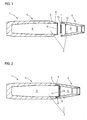
- FIG. 1 shows a cross-sectional view of a projectile according to the invention 1 in unassembled state.
- the projectile 1 comprises a projectile casing 3 surrounding a charge 2.
- the projectile casing 3 has two sections 4, 5 which each have a connecting region 6, 7. By means of the connecting regions 6, 7, the two sections 4, 5 are connectable to each other, which will be discussed below.
- the charge 2 comprises two partial charges 8, 9, which are arranged axially one behind the other viewed in the direction of movement of the projectile. Each of the two partial charges 8, 9 is received in a section 4, 5.
- the partial charge 8 is received in the section 4 and the partial charge 9 in the section 5.
- FIG. 1 shows essentially an exploded view of the unmounted projectile 1. Between the two sections 4, 5, a compensation element 10 is arranged. This is arranged between the two cover plates 11, 12, which secure the partial charges 8, 9 in the sections 4, 5.
- FIG. 2 shows the assembled state of the projectile 1 of FIG. 1 ,
- the two sections 4, 5 are connected to one another via the connecting regions 6, 7.
- the connecting portions 6, 7 are formed as a thread, wherein the Connecting portion 7 as an internal thread and the connecting portion 6 is formed as an external thread.
- the compensating element 10 is elastically deformed under construction of a restoring force, so compressed, so that this on the partial charges 8, 9 exerts a biasing force that biases the partial charges 8, 9 against the projectile casing 3.
- the cover plates 11, 12 are designed such that the force generated by the compensation element 10 can be passed to the partial charge 8, 9.
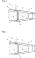
- FIG. 3 shows a detail of the projectile 1 of FIG. 1 during assembly.
- the two sections 4, 5 of the projectile 1 are partially connected to each other, wherein the connecting portions 6, 7 are partially screwed.
- the compensation element 10, which is formed in this example as an elastic disc is not deformed.
- the compensating element 10 is deformed, whereby an elastic restoring force is established, which biases the partial charge 8, 9.
- FIG. 4 shows the representation of FIG. 3 in assembled condition.
- the compensation element 10 has been deformed by the assembly process, so that the elastic restoring force sets.
- the two sections 4, 5 are completely screwed together via the connecting regions 6, 7.
- the compensation element 10 it is ensured by the compensation element 10 that the partial charges 8, 9 can not detach from the projectile casing 3, so that no gap between the partial charges 8, 9 and the projectile casing 3 is formed.
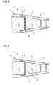
- FIG. 5 shows one too FIG. 3 similar representation, wherein two compensating elements 13, 14 are provided between the partial charges 8, 9.
- the compensating elements 13, 14 are not formed as the compensating element 10 as an elastic disc, but as elastic rings.
- the compensating element 13 has a smaller diameter than the compensating element 14 FIG. 5 the compensation elements 13, 14 are still undeformed, since the two connecting portions 6, 7 are not completely engaged or screwed on each other.
- FIG. 6 shows the representation of FIG. 5 in fully assembled state of the projectile 1. Obviously, the two connecting portions 6, 7 were completely screwed together, so that the compensation elements 13, 14 were deformed. As already described, the deformation results in the elastic preload force on the two partial charges 8, 9.
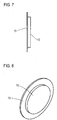
- FIG. 7 shows the compensating element 10, which is arranged on a holding element 15.
- the compensating element 10 is, as already described, formed as an elastic disc and connected to the holding element 15, for example, vulcanized or glued.
- the holding element 15 is disc-shaped and made for example of metal or plastic.
- FIG. 8 shows a perspective view of the compensating element 10 and the holding member 15 of FIG. 7 ,
- the arrangement of the compensating element 10 on the holding element 15 ensures that the compensating element 15 can be centered and positioned in the projectile 1.
- FIG. 9 shows compensating elements 16 to 19, which are arranged on the holding element 15.
- the compensating element 16 is essentially disk-shaped and the compensating elements 17 to 19 are designed as annular compensating elements with a rectangular cross-section.
- the compensating elements 16 to 19 are arranged concentrically to the center of the holding element 15.
- the arrangement of the compensation elements 17 to 19 on the holding element 15 whose relative position is fixed to each other and ensures that it is maintained.
- the holding element 15 fulfills the task that the compensating elements 16 to 19 centered and positioned in the projectile 1 can be introduced and can retain their position during the assembly-related deformation.
- FIG. 10 shows compensating elements 20 to 22, which in turn are arranged on the holding element 15.
- the compensation elements 20 to 22 are arranged concentrically to the center of the holding element 15 and are designed as annular compensation elements with an annular cross-section.
- FIG. 11 shows compensating elements 23 to 26, which are formed as annular compensating elements with annular cross-sections. These are arranged between two holding elements 27, 28, which are formed as circular disks. The holding elements 27, 28 have recesses 29, the compensation elements 23rd to 26 partially record. As a result, the centering and positioning of the compensation elements 23 to 26 is further improved.
- the arrangement of the compensating elements 23 to 26 between the two holding elements 27, 28, a "sandwich structure" is formed.
- the individual embodiments of the compensation elements and the provision of one or more holding elements can be combined with each other, if this makes sense technically.
- the compensating element (s) can also be made of a viscoelastic material.
Landscapes
- Engineering & Computer Science (AREA)
- Manufacturing & Machinery (AREA)
- General Engineering & Computer Science (AREA)
- Chemical & Material Sciences (AREA)
- Combustion & Propulsion (AREA)
- Aiming, Guidance, Guns With A Light Source, Armor, Camouflage, And Targets (AREA)
- Toys (AREA)
Claims (12)
- Projectile (1) comprenant une enveloppe de projectile (3) entourant une charge (2), dans lequel l'enveloppe de projectile (3) comporte deux sections (4, 5) présentant chacune une zone de liaison (6, 7) au moyen de laquelle les deux sections (4, 5) peuvent être reliées ou sont reliées entre elles, dans lequel la charge (2) comprend au moins deux charges partielles (8, 9) disposées axialement les unes derrière les autres et au moins une charge partielle (8, 9) est reçue dans chaque section, dans lequel au moins un élément de compensation (10, 13, 14, 16 à 19, 20 à 26) est disposé entre lesdites au moins deux charges partielles (8, 9) afin de générer une force de précontrainte dans l'état monté sur les deux charges partielles (8, 9), de manière à ce qu'elles soient au moins par sections en contact avec l'enveloppe de projectile (3),
caractérisé en ce qu'une plaque de recouvrement (11, 12) qui est tournée vers l'autre section (4, 5) respective est disposée sur au moins une charge partielle (8, 9). - Projectile selon la revendication 1,
caractérisé en ce que l'élément de compensation (10, 13, 14, 16 à 19, 20 à 26) est constitué d'un matériau élastique, en particulier d'un élastomère, ou d'un matériau viscoélastique, ou comprend un tel matériau. - Projectile selon la revendication 1 ou 2,
caractérisé en ce que l'élément de compensation (10, 13, 14, 16 à 19, 20 à 26) est constitué d'un matériau dont le coefficient de dilatation thermique est différent de celui de la charge (2). - Projectile selon l'une des revendications précédentes,
caractérisé en ce qu'au moins un élément de compensation (10, 13, 14, 16 à 19, 20 à 26) est réalisé sous forme annulaire, avec une section transversale circulaire ou rectangulaire, et/ou en ce qu'au moins un élément de compensation (10, 13, 14, 16 à 19, 20 à 26) est réalisé sous forme de disque ou sous forme de plaque et/ou en ce qu'au moins un élément de compensation (10, 13, 14, 16 à 19, 20 à 26) est réalisé sous forme de ruban, avec une section transversale circulaire ou rectangulaire. - Projectile selon l'une des revendications précédentes,
caractérisé en ce que ledit au moins un élément de compensation (10, 13, 14, 16 à 19, 20 à 26) est disposé sur au moins un élément de maintien (15, 26, 27). - Projectile selon la revendication 5,
caractérisé en ce que l'élément de maintien (15, 26, 27) est réalisé en matière plastique ou en métal. - Projectile selon la revendication 5 ou 6,
caractérisé en ce que l'élément de compensation (10, 13, 14, 16 à 19, 20 à 26) est disposé sur l'élément de maintien (15, 26, 27) par collage ou vulcanisation ou en ce que l'élément de compensation (10, 13, 14, 16 à 19, 20 à 26) et l'élément de maintien (15, 15, 26, 27) sont réalisés sous forme d'une pièce en matière plastique à deux constituants. - Projectile selon l'une des revendications 5 à 7,
caractérisé en ce que l'élément de maintien (15, 26, 27) est réalisé sous forme de disque ou de plaque. - Projectile selon l'une des revendications 5 à 8,
caractérisé en ce que l'élément de maintien (15, 26, 27) présente au moins un évidement tourné vers l'une des charges partielles (8, 9), dans lequel est disposé au moins par sections l'élément de compensation (10, 13, 14, 16 à 19, 20 à 26). - Projectile selon l'une des revendications précédentes,
caractérisé en ce que les zones de liaison (6, 7) sont réalisées sous forme de filetages complémentaires. - Projectile selon la revendication 10,
caractérisé en ce que les zones de liaison (6, 7) forment un point de rupture prédéterminé du projectile (1). - Projectile selon l'une des revendications précédentes,
caractérisé en ce qu'au moins une charge partielle (8, 9) est comprimée dans une section (4, 5).
Applications Claiming Priority (1)
| Application Number | Priority Date | Filing Date | Title |
|---|---|---|---|
| DE102016008391.3A DE102016008391B4 (de) | 2016-07-09 | 2016-07-09 | Geschoss |
Publications (2)
| Publication Number | Publication Date |
|---|---|
| EP3267143A1 EP3267143A1 (fr) | 2018-01-10 |
| EP3267143B1 true EP3267143B1 (fr) | 2019-03-06 |
Family
ID=59284968
Family Applications (1)
| Application Number | Title | Priority Date | Filing Date |
|---|---|---|---|
| EP17001130.8A Active EP3267143B1 (fr) | 2016-07-09 | 2017-07-03 | Projectile |
Country Status (4)
| Country | Link |
|---|---|
| EP (1) | EP3267143B1 (fr) |
| DE (1) | DE102016008391B4 (fr) |
| ES (1) | ES2728073T3 (fr) |
| TR (1) | TR201907089T4 (fr) |
Families Citing this family (1)
| Publication number | Priority date | Publication date | Assignee | Title |
|---|---|---|---|---|
| DE102020116228B3 (de) | 2020-06-19 | 2021-12-23 | Rheinmetall Waffe Munition Gmbh | Geschoss und Munition |
Citations (24)
| Publication number | Priority date | Publication date | Assignee | Title |
|---|---|---|---|---|
| DE12901C (de) | H. GRUSON, Kgl. Kommerzien-Rath in Buckau-Magdeburg, A. HEILHOFF, Artillerie-Offizier in Mainz, und J. A. HALBMAYR in Marienbad (Böhmen) | Hohlprojektile mit mehreren Abtheilungen zur Aufnahme brisanter Sprengstoffe | ||
| GB191301868A (en) | 1913-01-23 | 1913-12-04 | Whitworth & Co | Improvements in High Explosive Shells. |
| GB259539A (en) | 1925-10-12 | 1927-07-21 | Bohdan Pantoflicek | Improvements in or relating to bombs or the like |
| US2056098A (en) | 1935-07-16 | 1936-09-29 | Jr Martin Gavlak | Ammunition |
| US2321128A (en) | 1941-03-27 | 1943-06-08 | Robert R Clark | Explosive bullet |
| US2326147A (en) | 1940-01-16 | 1943-08-10 | William J Landen | Projectile |
| US2363024A (en) | 1941-02-06 | 1944-11-21 | Wilfred E Thibodeau | Explosive projectile |
| US2424970A (en) | 1940-01-19 | 1947-08-05 | Joseph H Church | Explosive projectile |
| FR2363077A1 (fr) | 1976-08-23 | 1978-03-24 | Foerenade Fabriksverken | Dispositif d'ejection et de separation de plusieurs elements loges dans une ogive ou analogue |
| US4365556A (en) | 1980-10-06 | 1982-12-28 | The United States Of America As Represented By The Secretary Of The Army | Method and system for preventing base separation of cast explosives in projectiles |
| DE3408113C1 (de) | 1984-03-06 | 1985-05-23 | Messerschmitt-Bölkow-Blohm GmbH, 8012 Ottobrunn | Gefechtskopf |
| DE3728105A1 (de) | 1986-03-01 | 1989-03-02 | Messerschmitt Boelkow Blohm | Geschoss |
| DE3929020A1 (de) | 1989-09-01 | 1991-03-21 | Diehl Gmbh & Co | Zuender fuer die sprengladung eines splittergeschosses |
| DE69100830T2 (de) | 1990-07-17 | 1994-05-05 | Manurhin Defense Versailles | Beim Aufschlag explodierendes Geschoss mit zerstörender Wirkung. |
| DE69512158T2 (de) | 1994-07-22 | 2000-01-20 | Manurhin Defense, Versailles | Explosives Geschoss |
| EP1338860A2 (fr) | 2002-02-21 | 2003-08-27 | Rheinmetall W & M GmbH | Procédé de fabrication d'un projectile explosif de grand calibre et projectile produit avec une telle méthode |
| EP1533590A1 (fr) | 2003-11-17 | 2005-05-25 | Giat Industries | Obus explosif ayant une tenue aux chocs améliorée |
| EP1292804B1 (fr) | 2000-06-19 | 2006-09-13 | RUAG Munition | Projectile autopropulse a noyau de penetration |
| DE102005019801A1 (de) | 2005-04-29 | 2006-11-02 | TDW Gesellschaft für verteidigungstechnische Wirksysteme mbH | Vorrichtung für kunststoffgebundene gegossene Sprengstoffe |
| DE102005050973A1 (de) | 2005-10-25 | 2007-04-26 | Rheinmetall Waffe Munition Gmbh | Sprenggeschoss |
| DE102008010706A1 (de) | 2008-02-22 | 2009-08-27 | Rheinmetall Waffe Munition Gmbh | Sprenggeschoss |
| DE102008010707A1 (de) | 2008-02-22 | 2009-08-27 | Rheinmetall Waffe Munition Gmbh | Sprenggeschoss und Verfahren zu seiner Herstellung |
| DE102009022495A1 (de) | 2009-05-25 | 2010-12-02 | Rheinmetall Waffe Munition Gmbh | Verfahren zur Herstellung eines großkalibrigen Sprenggeschosses und Sprenggeschoss, hergestellt nach diesem Verfahren |
| DE102013014811A1 (de) | 2013-09-05 | 2015-03-05 | Diehl Bgt Defence Gmbh & Co. Kg | Geschoss |
-
2016
- 2016-07-09 DE DE102016008391.3A patent/DE102016008391B4/de not_active Revoked
-
2017
- 2017-07-03 EP EP17001130.8A patent/EP3267143B1/fr active Active
- 2017-07-03 TR TR2019/07089T patent/TR201907089T4/tr unknown
- 2017-07-03 ES ES17001130T patent/ES2728073T3/es active Active
Patent Citations (25)
| Publication number | Priority date | Publication date | Assignee | Title |
|---|---|---|---|---|
| DE12901C (de) | H. GRUSON, Kgl. Kommerzien-Rath in Buckau-Magdeburg, A. HEILHOFF, Artillerie-Offizier in Mainz, und J. A. HALBMAYR in Marienbad (Böhmen) | Hohlprojektile mit mehreren Abtheilungen zur Aufnahme brisanter Sprengstoffe | ||
| GB191301868A (en) | 1913-01-23 | 1913-12-04 | Whitworth & Co | Improvements in High Explosive Shells. |
| GB259539A (en) | 1925-10-12 | 1927-07-21 | Bohdan Pantoflicek | Improvements in or relating to bombs or the like |
| US2056098A (en) | 1935-07-16 | 1936-09-29 | Jr Martin Gavlak | Ammunition |
| US2326147A (en) | 1940-01-16 | 1943-08-10 | William J Landen | Projectile |
| US2424970A (en) | 1940-01-19 | 1947-08-05 | Joseph H Church | Explosive projectile |
| US2363024A (en) | 1941-02-06 | 1944-11-21 | Wilfred E Thibodeau | Explosive projectile |
| US2321128A (en) | 1941-03-27 | 1943-06-08 | Robert R Clark | Explosive bullet |
| FR2363077A1 (fr) | 1976-08-23 | 1978-03-24 | Foerenade Fabriksverken | Dispositif d'ejection et de separation de plusieurs elements loges dans une ogive ou analogue |
| US4365556A (en) | 1980-10-06 | 1982-12-28 | The United States Of America As Represented By The Secretary Of The Army | Method and system for preventing base separation of cast explosives in projectiles |
| DE3408113C1 (de) | 1984-03-06 | 1985-05-23 | Messerschmitt-Bölkow-Blohm GmbH, 8012 Ottobrunn | Gefechtskopf |
| DE3728105A1 (de) | 1986-03-01 | 1989-03-02 | Messerschmitt Boelkow Blohm | Geschoss |
| DE3929020A1 (de) | 1989-09-01 | 1991-03-21 | Diehl Gmbh & Co | Zuender fuer die sprengladung eines splittergeschosses |
| DE69100830T2 (de) | 1990-07-17 | 1994-05-05 | Manurhin Defense Versailles | Beim Aufschlag explodierendes Geschoss mit zerstörender Wirkung. |
| DE69512158T2 (de) | 1994-07-22 | 2000-01-20 | Manurhin Defense, Versailles | Explosives Geschoss |
| EP1292804B1 (fr) | 2000-06-19 | 2006-09-13 | RUAG Munition | Projectile autopropulse a noyau de penetration |
| EP1338860A2 (fr) | 2002-02-21 | 2003-08-27 | Rheinmetall W & M GmbH | Procédé de fabrication d'un projectile explosif de grand calibre et projectile produit avec une telle méthode |
| US20040031380A1 (en) | 2002-02-21 | 2004-02-19 | Ernst-Wilhelm Altenau | Method for producing a large-caliber, high-explosive projectile, and high-explosive projectile produced in accordance with the method |
| EP1533590A1 (fr) | 2003-11-17 | 2005-05-25 | Giat Industries | Obus explosif ayant une tenue aux chocs améliorée |
| DE102005019801A1 (de) | 2005-04-29 | 2006-11-02 | TDW Gesellschaft für verteidigungstechnische Wirksysteme mbH | Vorrichtung für kunststoffgebundene gegossene Sprengstoffe |
| DE102005050973A1 (de) | 2005-10-25 | 2007-04-26 | Rheinmetall Waffe Munition Gmbh | Sprenggeschoss |
| DE102008010706A1 (de) | 2008-02-22 | 2009-08-27 | Rheinmetall Waffe Munition Gmbh | Sprenggeschoss |
| DE102008010707A1 (de) | 2008-02-22 | 2009-08-27 | Rheinmetall Waffe Munition Gmbh | Sprenggeschoss und Verfahren zu seiner Herstellung |
| DE102009022495A1 (de) | 2009-05-25 | 2010-12-02 | Rheinmetall Waffe Munition Gmbh | Verfahren zur Herstellung eines großkalibrigen Sprenggeschosses und Sprenggeschoss, hergestellt nach diesem Verfahren |
| DE102013014811A1 (de) | 2013-09-05 | 2015-03-05 | Diehl Bgt Defence Gmbh & Co. Kg | Geschoss |
Also Published As
| Publication number | Publication date |
|---|---|
| TR201907089T4 (tr) | 2019-06-21 |
| DE102016008391A1 (de) | 2018-01-11 |
| EP3267143A1 (fr) | 2018-01-10 |
| ES2728073T3 (es) | 2019-10-22 |
| DE102016008391B4 (de) | 2018-05-24 |
Similar Documents
| Publication | Publication Date | Title |
|---|---|---|
| EP1995088B1 (fr) | Elément de palier d'insertion, élément de palier d'insertion élastique et dispositif de support de jambe de suspension à ressort | |
| EP0291845B1 (fr) | Projectile à noyau et à enveloppe | |
| DE20320359U1 (de) | Projektildichtungsanordnung | |
| EP1851503A1 (fr) | Projectile | |
| DE69213861T2 (de) | Unterkalibriges Wuchtgeschoss mit Splitterwirkung | |
| DE102016008391B4 (de) | Geschoss | |
| DE102004031875A1 (de) | Deckel für eine Luftfeder | |
| EP0513472B1 (fr) | Sous-munition pour projectile porteur stabilisé par rotation | |
| DE69213612T2 (de) | Wuchtgeschoss mit splitterwirkung | |
| EP0200709A2 (fr) | Capteur de pression | |
| DE60007943T2 (de) | Verbindungsteil zwischen Geschoss und Geschosshülse und Methode zur Montage eines Dichtringes mittels eines derartigen Verbindungteiles | |
| EP0219490B1 (fr) | Assemblage de garniture mécanique d'étanchéité | |
| DE102015211765A1 (de) | Axialkugelgelenk | |
| DE102018005202A1 (de) | Aktivierungseinrichtung für eine Batterie für einen elektronischen Zündmechanismus | |
| DE69200400T2 (de) | Übungsmine. | |
| DE102013014811A1 (de) | Geschoss | |
| DE102011011478A1 (de) | Zerlegegeschoss | |
| WO2014170152A1 (fr) | Projectile de sabot | |
| EP1687545B1 (fr) | Assemblage par compression non destructive sur des elements de fixation pyromecaniques | |
| DE60027676T2 (de) | Treibladungszünder für Artilleriemunition | |
| EP2324322B1 (fr) | Obus de mortier | |
| DE60017481T2 (de) | Festtreibstoffraketenmotor mit Sicherheitsvorrichtung für starke thermische Spannungen | |
| EP2905572B1 (fr) | Douille de charge propulsive pour munition encartouchée | |
| EP2314980A2 (fr) | Dispositif d'amortissement pour pièces d'insertion dans des pénétrateurs | |
| DE102008017882B4 (de) | Federeinrichtung |
Legal Events
| Date | Code | Title | Description |
|---|---|---|---|
| PUAI | Public reference made under article 153(3) epc to a published international application that has entered the european phase |
Free format text: ORIGINAL CODE: 0009012 |
|
| STAA | Information on the status of an ep patent application or granted ep patent |
Free format text: STATUS: THE APPLICATION HAS BEEN PUBLISHED |
|
| AK | Designated contracting states |
Kind code of ref document: A1 Designated state(s): AL AT BE BG CH CY CZ DE DK EE ES FI FR GB GR HR HU IE IS IT LI LT LU LV MC MK MT NL NO PL PT RO RS SE SI SK SM TR |
|
| AX | Request for extension of the european patent |
Extension state: BA ME |
|
| STAA | Information on the status of an ep patent application or granted ep patent |
Free format text: STATUS: REQUEST FOR EXAMINATION WAS MADE |
|
| 17P | Request for examination filed |
Effective date: 20180705 |
|
| RBV | Designated contracting states (corrected) |
Designated state(s): AL AT BE BG CH CY CZ DE DK EE ES FI FR GB GR HR HU IE IS IT LI LT LU LV MC MK MT NL NO PL PT RO RS SE SI SK SM TR |
|
| GRAP | Despatch of communication of intention to grant a patent |
Free format text: ORIGINAL CODE: EPIDOSNIGR1 |
|
| STAA | Information on the status of an ep patent application or granted ep patent |
Free format text: STATUS: GRANT OF PATENT IS INTENDED |
|
| RIC1 | Information provided on ipc code assigned before grant |
Ipc: F42B 33/02 20060101AFI20180904BHEP Ipc: F42B 33/00 20060101ALI20180904BHEP |
|
| INTG | Intention to grant announced |
Effective date: 20180920 |
|
| GRAS | Grant fee paid |
Free format text: ORIGINAL CODE: EPIDOSNIGR3 |
|
| GRAA | (expected) grant |
Free format text: ORIGINAL CODE: 0009210 |
|
| STAA | Information on the status of an ep patent application or granted ep patent |
Free format text: STATUS: THE PATENT HAS BEEN GRANTED |
|
| AK | Designated contracting states |
Kind code of ref document: B1 Designated state(s): AL AT BE BG CH CY CZ DE DK EE ES FI FR GB GR HR HU IE IS IT LI LT LU LV MC MK MT NL NO PL PT RO RS SE SI SK SM TR |
|
| REG | Reference to a national code |
Ref country code: GB Ref legal event code: FG4D Free format text: NOT ENGLISH |
|
| REG | Reference to a national code |
Ref country code: CH Ref legal event code: EP Ref country code: AT Ref legal event code: REF Ref document number: 1105148 Country of ref document: AT Kind code of ref document: T Effective date: 20190315 |
|
| REG | Reference to a national code |
Ref country code: DE Ref legal event code: R096 Ref document number: 502017000841 Country of ref document: DE |
|
| REG | Reference to a national code |
Ref country code: IE Ref legal event code: FG4D Free format text: LANGUAGE OF EP DOCUMENT: GERMAN |
|
| REG | Reference to a national code |
Ref country code: NL Ref legal event code: MP Effective date: 20190306 |
|
| REG | Reference to a national code |
Ref country code: LT Ref legal event code: MG4D |
|
| PG25 | Lapsed in a contracting state [announced via postgrant information from national office to epo] |
Ref country code: FI Free format text: LAPSE BECAUSE OF FAILURE TO SUBMIT A TRANSLATION OF THE DESCRIPTION OR TO PAY THE FEE WITHIN THE PRESCRIBED TIME-LIMIT Effective date: 20190306 Ref country code: LT Free format text: LAPSE BECAUSE OF FAILURE TO SUBMIT A TRANSLATION OF THE DESCRIPTION OR TO PAY THE FEE WITHIN THE PRESCRIBED TIME-LIMIT Effective date: 20190306 Ref country code: SE Free format text: LAPSE BECAUSE OF FAILURE TO SUBMIT A TRANSLATION OF THE DESCRIPTION OR TO PAY THE FEE WITHIN THE PRESCRIBED TIME-LIMIT Effective date: 20190306 |
|
| REG | Reference to a national code |
Ref country code: NO Ref legal event code: T2 Effective date: 20190306 |
|
| PG25 | Lapsed in a contracting state [announced via postgrant information from national office to epo] |
Ref country code: RS Free format text: LAPSE BECAUSE OF FAILURE TO SUBMIT A TRANSLATION OF THE DESCRIPTION OR TO PAY THE FEE WITHIN THE PRESCRIBED TIME-LIMIT Effective date: 20190306 Ref country code: HR Free format text: LAPSE BECAUSE OF FAILURE TO SUBMIT A TRANSLATION OF THE DESCRIPTION OR TO PAY THE FEE WITHIN THE PRESCRIBED TIME-LIMIT Effective date: 20190306 Ref country code: LV Free format text: LAPSE BECAUSE OF FAILURE TO SUBMIT A TRANSLATION OF THE DESCRIPTION OR TO PAY THE FEE WITHIN THE PRESCRIBED TIME-LIMIT Effective date: 20190306 Ref country code: GR Free format text: LAPSE BECAUSE OF FAILURE TO SUBMIT A TRANSLATION OF THE DESCRIPTION OR TO PAY THE FEE WITHIN THE PRESCRIBED TIME-LIMIT Effective date: 20190607 Ref country code: BG Free format text: LAPSE BECAUSE OF FAILURE TO SUBMIT A TRANSLATION OF THE DESCRIPTION OR TO PAY THE FEE WITHIN THE PRESCRIBED TIME-LIMIT Effective date: 20190606 Ref country code: NL Free format text: LAPSE BECAUSE OF FAILURE TO SUBMIT A TRANSLATION OF THE DESCRIPTION OR TO PAY THE FEE WITHIN THE PRESCRIBED TIME-LIMIT Effective date: 20190306 |
|
| REG | Reference to a national code |
Ref country code: ES Ref legal event code: FG2A Ref document number: 2728073 Country of ref document: ES Kind code of ref document: T3 Effective date: 20191022 |
|
| PG25 | Lapsed in a contracting state [announced via postgrant information from national office to epo] |
Ref country code: AL Free format text: LAPSE BECAUSE OF FAILURE TO SUBMIT A TRANSLATION OF THE DESCRIPTION OR TO PAY THE FEE WITHIN THE PRESCRIBED TIME-LIMIT Effective date: 20190306 Ref country code: PT Free format text: LAPSE BECAUSE OF FAILURE TO SUBMIT A TRANSLATION OF THE DESCRIPTION OR TO PAY THE FEE WITHIN THE PRESCRIBED TIME-LIMIT Effective date: 20190706 Ref country code: CZ Free format text: LAPSE BECAUSE OF FAILURE TO SUBMIT A TRANSLATION OF THE DESCRIPTION OR TO PAY THE FEE WITHIN THE PRESCRIBED TIME-LIMIT Effective date: 20190306 Ref country code: SK Free format text: LAPSE BECAUSE OF FAILURE TO SUBMIT A TRANSLATION OF THE DESCRIPTION OR TO PAY THE FEE WITHIN THE PRESCRIBED TIME-LIMIT Effective date: 20190306 Ref country code: RO Free format text: LAPSE BECAUSE OF FAILURE TO SUBMIT A TRANSLATION OF THE DESCRIPTION OR TO PAY THE FEE WITHIN THE PRESCRIBED TIME-LIMIT Effective date: 20190306 Ref country code: EE Free format text: LAPSE BECAUSE OF FAILURE TO SUBMIT A TRANSLATION OF THE DESCRIPTION OR TO PAY THE FEE WITHIN THE PRESCRIBED TIME-LIMIT Effective date: 20190306 |
|
| PG25 | Lapsed in a contracting state [announced via postgrant information from national office to epo] |
Ref country code: SM Free format text: LAPSE BECAUSE OF FAILURE TO SUBMIT A TRANSLATION OF THE DESCRIPTION OR TO PAY THE FEE WITHIN THE PRESCRIBED TIME-LIMIT Effective date: 20190306 Ref country code: PL Free format text: LAPSE BECAUSE OF FAILURE TO SUBMIT A TRANSLATION OF THE DESCRIPTION OR TO PAY THE FEE WITHIN THE PRESCRIBED TIME-LIMIT Effective date: 20190306 |
|
| REG | Reference to a national code |
Ref country code: DE Ref legal event code: R026 Ref document number: 502017000841 Country of ref document: DE |
|
| PLBI | Opposition filed |
Free format text: ORIGINAL CODE: 0009260 |
|
| PG25 | Lapsed in a contracting state [announced via postgrant information from national office to epo] |
Ref country code: IS Free format text: LAPSE BECAUSE OF FAILURE TO SUBMIT A TRANSLATION OF THE DESCRIPTION OR TO PAY THE FEE WITHIN THE PRESCRIBED TIME-LIMIT Effective date: 20190706 |
|
| PLAX | Notice of opposition and request to file observation + time limit sent |
Free format text: ORIGINAL CODE: EPIDOSNOBS2 |
|
| 26 | Opposition filed |
Opponent name: RHEINMETALL WAFFE MUNITION GMBH Effective date: 20191204 |
|
| PG25 | Lapsed in a contracting state [announced via postgrant information from national office to epo] |
Ref country code: DK Free format text: LAPSE BECAUSE OF FAILURE TO SUBMIT A TRANSLATION OF THE DESCRIPTION OR TO PAY THE FEE WITHIN THE PRESCRIBED TIME-LIMIT Effective date: 20190306 |
|
| PG25 | Lapsed in a contracting state [announced via postgrant information from national office to epo] |
Ref country code: MC Free format text: LAPSE BECAUSE OF FAILURE TO SUBMIT A TRANSLATION OF THE DESCRIPTION OR TO PAY THE FEE WITHIN THE PRESCRIBED TIME-LIMIT Effective date: 20190306 Ref country code: SI Free format text: LAPSE BECAUSE OF FAILURE TO SUBMIT A TRANSLATION OF THE DESCRIPTION OR TO PAY THE FEE WITHIN THE PRESCRIBED TIME-LIMIT Effective date: 20190306 |
|
| REG | Reference to a national code |
Ref country code: BE Ref legal event code: MM Effective date: 20190731 |
|
| PG25 | Lapsed in a contracting state [announced via postgrant information from national office to epo] |
Ref country code: BE Free format text: LAPSE BECAUSE OF NON-PAYMENT OF DUE FEES Effective date: 20190731 Ref country code: LU Free format text: LAPSE BECAUSE OF NON-PAYMENT OF DUE FEES Effective date: 20190703 |
|
| PLBB | Reply of patent proprietor to notice(s) of opposition received |
Free format text: ORIGINAL CODE: EPIDOSNOBS3 |
|
| PG25 | Lapsed in a contracting state [announced via postgrant information from national office to epo] |
Ref country code: IE Free format text: LAPSE BECAUSE OF NON-PAYMENT OF DUE FEES Effective date: 20190703 |
|
| REG | Reference to a national code |
Ref country code: CH Ref legal event code: PL |
|
| PG25 | Lapsed in a contracting state [announced via postgrant information from national office to epo] |
Ref country code: LI Free format text: LAPSE BECAUSE OF NON-PAYMENT OF DUE FEES Effective date: 20200731 Ref country code: CH Free format text: LAPSE BECAUSE OF NON-PAYMENT OF DUE FEES Effective date: 20200731 |
|
| PG25 | Lapsed in a contracting state [announced via postgrant information from national office to epo] |
Ref country code: CY Free format text: LAPSE BECAUSE OF FAILURE TO SUBMIT A TRANSLATION OF THE DESCRIPTION OR TO PAY THE FEE WITHIN THE PRESCRIBED TIME-LIMIT Effective date: 20190306 |
|
| PG25 | Lapsed in a contracting state [announced via postgrant information from national office to epo] |
Ref country code: HU Free format text: LAPSE BECAUSE OF FAILURE TO SUBMIT A TRANSLATION OF THE DESCRIPTION OR TO PAY THE FEE WITHIN THE PRESCRIBED TIME-LIMIT; INVALID AB INITIO Effective date: 20170703 Ref country code: MT Free format text: LAPSE BECAUSE OF FAILURE TO SUBMIT A TRANSLATION OF THE DESCRIPTION OR TO PAY THE FEE WITHIN THE PRESCRIBED TIME-LIMIT Effective date: 20190306 |
|
| REG | Reference to a national code |
Ref country code: DE Ref legal event code: R100 Ref document number: 502017000841 Country of ref document: DE |
|
| PLCK | Communication despatched that opposition was rejected |
Free format text: ORIGINAL CODE: EPIDOSNREJ1 |
|
| PLAB | Opposition data, opponent's data or that of the opponent's representative modified |
Free format text: ORIGINAL CODE: 0009299OPPO |
|
| GBPC | Gb: european patent ceased through non-payment of renewal fee |
Effective date: 20210703 |
|
| R26 | Opposition filed (corrected) |
Opponent name: RHEINMETALL WAFFE MUNITION GMBH Effective date: 20191204 |
|
| PG25 | Lapsed in a contracting state [announced via postgrant information from national office to epo] |
Ref country code: GB Free format text: LAPSE BECAUSE OF NON-PAYMENT OF DUE FEES Effective date: 20210703 |
|
| PLBN | Opposition rejected |
Free format text: ORIGINAL CODE: 0009273 |
|
| STAA | Information on the status of an ep patent application or granted ep patent |
Free format text: STATUS: OPPOSITION REJECTED |
|
| 27O | Opposition rejected |
Effective date: 20220112 |
|
| PG25 | Lapsed in a contracting state [announced via postgrant information from national office to epo] |
Ref country code: MK Free format text: LAPSE BECAUSE OF FAILURE TO SUBMIT A TRANSLATION OF THE DESCRIPTION OR TO PAY THE FEE WITHIN THE PRESCRIBED TIME-LIMIT Effective date: 20190306 |
|
| REG | Reference to a national code |
Ref country code: AT Ref legal event code: MM01 Ref document number: 1105148 Country of ref document: AT Kind code of ref document: T Effective date: 20220703 |
|
| PG25 | Lapsed in a contracting state [announced via postgrant information from national office to epo] |
Ref country code: AT Free format text: LAPSE BECAUSE OF NON-PAYMENT OF DUE FEES Effective date: 20220703 |
|
| PGFP | Annual fee paid to national office [announced via postgrant information from national office to epo] |
Ref country code: ES Payment date: 20250826 Year of fee payment: 9 |
|
| PGFP | Annual fee paid to national office [announced via postgrant information from national office to epo] |
Ref country code: DE Payment date: 20250904 Year of fee payment: 9 |
|
| PGFP | Annual fee paid to national office [announced via postgrant information from national office to epo] |
Ref country code: NO Payment date: 20250725 Year of fee payment: 9 |
|
| PGFP | Annual fee paid to national office [announced via postgrant information from national office to epo] |
Ref country code: IT Payment date: 20250724 Year of fee payment: 9 |
|
| PGFP | Annual fee paid to national office [announced via postgrant information from national office to epo] |
Ref country code: FR Payment date: 20250725 Year of fee payment: 9 |
|
| PGFP | Annual fee paid to national office [announced via postgrant information from national office to epo] |
Ref country code: TR Payment date: 20260629 Year of fee payment: 10 |