EP3267270A1 - Fehlersicheres automatisierungssystem - Google Patents
Fehlersicheres automatisierungssystem Download PDFInfo
- Publication number
- EP3267270A1 EP3267270A1 EP16177938.4A EP16177938A EP3267270A1 EP 3267270 A1 EP3267270 A1 EP 3267270A1 EP 16177938 A EP16177938 A EP 16177938A EP 3267270 A1 EP3267270 A1 EP 3267270A1
- Authority
- EP
- European Patent Office
- Prior art keywords
- fail
- safe
- automation system
- assigned
- processor
- Prior art date
- Legal status (The legal status is an assumption and is not a legal conclusion. Google has not performed a legal analysis and makes no representation as to the accuracy of the status listed.)
- Granted
Links
Images


Classifications
-
- G—PHYSICS
- G05—CONTROLLING; REGULATING
- G05B—CONTROL OR REGULATING SYSTEMS IN GENERAL; FUNCTIONAL ELEMENTS OF SUCH SYSTEMS; MONITORING OR TESTING ARRANGEMENTS FOR SUCH SYSTEMS OR ELEMENTS
- G05B19/00—Program-control systems
- G05B19/02—Program-control systems electric
- G05B19/04—Program control other than numerical control, i.e. in sequence controllers or logic controllers
- G05B19/042—Program control other than numerical control, i.e. in sequence controllers or logic controllers using digital processors
- G05B19/0428—Safety, monitoring
-
- G—PHYSICS
- G05—CONTROLLING; REGULATING
- G05B—CONTROL OR REGULATING SYSTEMS IN GENERAL; FUNCTIONAL ELEMENTS OF SUCH SYSTEMS; MONITORING OR TESTING ARRANGEMENTS FOR SUCH SYSTEMS OR ELEMENTS
- G05B19/00—Program-control systems
- G05B19/02—Program-control systems electric
- G05B19/04—Program control other than numerical control, i.e. in sequence controllers or logic controllers
- G05B19/05—Programmable logic controllers, e.g. simulating logic interconnections of signals according to ladder diagrams or function charts
- G05B19/058—Safety, monitoring
-
- G—PHYSICS
- G05—CONTROLLING; REGULATING
- G05B—CONTROL OR REGULATING SYSTEMS IN GENERAL; FUNCTIONAL ELEMENTS OF SUCH SYSTEMS; MONITORING OR TESTING ARRANGEMENTS FOR SUCH SYSTEMS OR ELEMENTS
- G05B2219/00—Program-control systems
- G05B2219/10—Plc systems
- G05B2219/14—Plc safety
- G05B2219/14007—Plc as standalone for safety control of machine
Definitions
- the invention relates to a failsafe automation system according to the preamble of claim 1. Furthermore, the invention relates to an input system for a fail-safe automation system. In addition, the invention relates to a system.
- Fail-safe automation systems are used to control and / or regulate drives in safety-related areas such as industrial plants.
- automation systems use, by way of example, secure input methods, redundant (i.e., multiple) execution of individual elements of the automation system, and / or the secure transmission of signals between the individual elements.
- EP 2 192 461 A1 describes a control device and a system for fail-safe data transmission.
- the object is achieved by a fail-safe automation system according to claim 1.
- the object is further achieved by an input system according to claim 10 and by a system according to claim 11.
- the fail-safe automation system has a motion controller and at least one fail-safe processor.
- the fail-safe automation system has optional drives.
- the fail-safe automation system is used to control and / or regulate a plurality of drives.
- For the control and / or regulation of the drives is preferably the motion control.
- the drives are each assigned to an area, wherein the respective area is assigned in each case a security level and wherein the areas in each case adjacent to each other, in particular spatially adjacent, are arranged.
- the fail-safe processor may be implemented as a separate hardware component.
- the fail-safe processor can also be integrated in the motion control and / or in the drive.
- the fail-safe processor is preferably designed as a software module or as an additional computer program.
- An automation system is understood to mean at least a part of a drive system.
- the automation system advantageously includes components such as a motion controller, in particular an S PEICHER P rogrammierbare S controller (PLC), optionally processors, such as switching elements or network adapter (proxies, hosts) and optionally actuators on.
- the drives each have a power converter and a motor.
- a fail-safe automation system advantageously has a fail-safe motion control and / or fail-safe processors, wherein the fail-safe processors check, for example, the transmission of signals from the motion control to the drives.
- An automation system advantageously has a data connection for the transmission of data and / or signals.
- the plant is designed in particular as a production machine, machine tool or industrial plant, wherein the Plant has a fail-safe automation system described here.
- the drives are advantageously connected to the motion control.
- the drives have a power converter or a frequency converter and an electrical machine, in particular an (electric) motor on.
- a drive may include a brake and / or an encoder.
- the brake is preferably used for faster deceleration of the drive and / or to ensure the stoppage of the drive.
- a brake shortens the action time of the respective drive.
- the encoder is preferably used to verify the movement of the drive. Both the brake and the encoder can be connected to the motion control.
- a security level can be understood as meaning that a drive comes to a standstill within a predetermined time (action time) from its respective movement speed. The higher the security level, the lower the predetermined action time until the drive comes to a standstill. For an increase in the security level, moreover, a mechanical and / or electronic brake can be used.
- a certain level of security may be specified in accordance with legal requirements.
- the security level is particularly high.
- a fail-safe automation system is understood to mean an automation system which has one or more of the above-mentioned features of fail-safety.
- a fail-safe automation system or a fail-safe drive system can each also be characterized by a maximum speed of the respective drive.
- a fail-safe automation system may additionally or alternatively be distinguished by a defined reaction to an (incoming) signal. For example, it may be specified that opening a cover for a signal is only possible after a defined period of time.
- a security level is understood here to mean that the respective drive, which is assigned to the security level, is assigned a time duration, in particular a (re-) action time.
- the specified period of time is the time at which the drive reaches standstill at the latest.
- the fixed period of time may also be the period of time after which no more torque originates from the respective drive.
- the fixed period of time is also referred to here as the action time.
- a fail-safe processor can be understood as a module which supports or ensures secure transmission of data between the motion controller and the respective drive. Therefore, a fail-safe processor is preferably also designed as a communication module.
- a fail-safe processor is a fail-safe proxy block. Fail-safe means that a fail-safe interaction of several blocks can take place in an otherwise non-failsafe environment.
- the space in which the drives are located is divided into a plurality of areas.
- the areas are spatially adjacent and optionally substantially contiguous.
- a room is in particular an area of a production hall.
- the room has, by way of example, a first area, a second area and a third area.
- the first area may have the actual plant or production machine, in particular a press.
- the first area is assigned, for example, a first, eg low, security level.
- the second area extends around the plant by way of example.
- the second area are advantageously devices for equipping the system. If necessary, manual activities may be necessary here. Therefore, to protect the persons in the second area, a higher level of security may be necessary.
- the second area may adjoin the third area.
- the third area can be characterized by regular manual activities. Therefore, in this third area, a high level of security is necessary.
- the room is divided into the three areas, with each area having its own security level.
- the areas are each adjacent to each other in space, that is, the two areas each have a common boundary or are at least close to each other.
- the areas may also be separated by physical boundaries such as access locks, room dividers, corridors or (light) curtains.
- a security level can be assigned to the respective drive which is located in the respective area.
- the assignment can be made regardless of the connection of the respective drive to the motion control.
- the above object is achieved in such a way that the configuration can be configured flexibly by assigning the respective drive to the area or a security level.
- one area is assigned a fail-safe processor in each case.
- the fail-safe processor monitors the function of the respective drive in the assigned area.
- the fail-safe processor is connected to the motion control.
- the fail-safe processor ensures data exchange and / or signal exchange between the motion controller and the corresponding drive.
- the respective fail-safe processor is advantageously assigned to the respectively corresponding area.
- a fail-safe processor can be connected to the motion control.
- a fail-safe processor is assigned to each area.
- the respective security level can be ensured by a respective adapted fail-safe processor.
- one area can also be assigned a number of fail-safe processors.
- the respective drive and / or the respective fail-safe processor are connected via a fail-safe data connection.
- a fail-safe data connection is understood to be a data connection in which it is ensured that the correct signals or the correct data arrive at the intended time with the signal strength provided. Furthermore, the transmission of the correct data can be checked, in particular by a redundant design. A fail-safe transmission can be formed, for example, by a redundant transmission with subsequent comparison.
- fail-safe data connection An example of a fail-safe data connection is PROFIBUS or PROFINET from Siemens AG. Another fail-safe data connection is made by way of example using PROFIsafe addressing.
- connection of the individual components advantageously satisfies the chosen security standard.
- errors in the transmission of signals or data are revealed.
- the fail-safe automation system of the respective security level is assigned an action time, wherein the action time is a period of time from a trigger signal to the action of the respective drive.
- An action time is an example of the length of time that a switch needs to change a switching state.
- the monitoring time can also be composed of several switching times and / or braking times.
- the respective fail-safe processor is designed as fail-safe IO controller (input / output controller).
- the fail-safe processor is used in particular to avoid errors in the transmission of data and / or signals.
- a fail-safe processor is therefore advantageously designed as an IO controller (input-output controller or input / output controller), in particular for a so-called I-device communication, for example for a further processor or a further component.
- IO controller input-output controller or input / output controller
- a non-fail-safe component can become a fail-safe component.
- the fail-safe processor can also be designed as a so-called I-slave, in particular for a so-called I-slave communication for a processor, in particular a non-failsafe processor, or a corresponding component be.
- a non-failsafe processor is also called a standard processor.
- the latter embodiment can also be combined with fail-safe components, in particular further fail-safe processors.
- the fail-safe processor can also be provided for data transmission and / or signal transmission from and to a (further) fail-safe processor. This is also referred to as I slave to a direct data exchange and / or signal exchange.
- the fail-safe processor can also be provided as an IO controller with a (further) fail-safe processor, in particular for fail-safe transmission of signals and / or data. This is also known as shared-device functionality.
- a non-failsafe automation system can be upgraded to a fail-safe automation system at least in certain areas.
- the fail-safe processors are each connected to each other by a data connection.
- the fail-safe processors are interconnected.
- a fail-safe data connection is used to connect the fail-safe processors.
- the corresponding safety standard for example by redirecting the communication or a controlled shutdown of the machine, can be adhered to.
- Fail-safe processors are preferably designed as software modules. A connection of the fail-safe processors is then carried out by a data exchange of the software modules.
- connection of the fail-safe processors with each other is preferably used for redundancy in multiple fail-safe processors.
- a fail-safe processor in slave mode can forward data and / or signals to a fail-safe processor in master mode.
- the (direct) connection of the fail-safe processors serves for the rapid exchange of data.
- the drives and / or the fail-safe processors are each assigned to a zone.
- the zone is formed as one level each in a network or other connection scheme of the data connection. Different zones may each have different security unit levels.
- a zone can be understood as a fail-safe zone.
- drives that do not have special safety requirements can be assigned to a first zone.
- the first zone can therefore be characterized by a low to no security level. In the first zone, therefore, only one simple fail-safe processor is assigned. If necessary, no fail-safe processor is necessary.
- a network is understood here as the connection diagram of the individual components of the automation system.
- a network can also have a second and / or a third zone with higher security standards. Due to the increased security requirement, a higher level of error safety is necessary.
- An improved fail-safe transmission of data and / or signals in the zones of the network, which ensures a fail-safe communication in the network, can be ensured by further fail-safe processors, which are assigned to the respective zone of the network.
- the data transmission and / or signal transmission can be adapted to the requirements of the error safety of the individual drive.
- the respective fail-safe processor, the respective motion controller and / or the respective drive are of redundant design.
- a redundant design of a component such as a motion controller, a (fail-safe) processor or a (fail-safe) data connection means that the fail-safe automation system has the respective component multiple times.
- two components for example two fail-safe processors, interact with one another in such a way that, in a normal operation, the first component is designed as a master and performs corresponding functions and the second component is designed as a slave and performs corresponding functions. If a malfunction is detected in the first fail-safe processor, the second fail-safe processor (previously in the slave function) takes the place of the first fail-safe processor. The second fail-safe processor may continue to operate in the master function while the first fail-safe processor is placed in a slave function.
- the data and / or the signals are routed via the at least two data connections.
- an adjustment of the transmitted data or signals takes place.
- a data comparison or a signal comparison between the individual components of the automation system takes place via the data connection.
- this also has an input system, wherein the input system is provided for providing signals for the fail-safe automation system, wherein the input system is configured to assign the respective security level for the respective drive.
- the input system is advantageously designed analogously to an engineering system.
- the input system preferably serves for interaction with the user, wherein the user can specify motion sequences for the individual drives.
- the user can also assign the security level, the respective fail-safe processor and / or the respective monitoring time to the respective drive or another component.
- the input advantageously takes place with the aid of an input means.
- the input system may be integrated in an advantageous embodiment in a control program or interact with the control program data technology.
- the input system is designed as a computer program or as a computer program package.
- the input system can therefore be installed on a computer and executed on the computer.
- the input system is transferred to the main memory and executed with a processor of the arithmetic unit.
- the input system and / or the control program are advantageously used to provide data to the motion control and / or to the (fail-safe) processors or drives.
- the input system is also advantageous for specifying the zone of the network in which the fail-safe processor, the respective drive and / or the respective motion control are located.
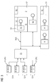
- FIG. 1 shows a fail-safe automation system.
- the fail-safe automation system has a motion controller BS, wherein the motion controller BS is connected to drives A1, A2, A3.
- the connection of the movement control BS with the respective drive A1, A2, A3 is carried out with a data connection BUS, wherein the data connection BUS is advantageously designed as fail-safe data connection BUS.
- the drives A1, A2, A3 are each assigned to a range S1, S2, S3.
- a first drive A1 is assigned to a first area S1.
- a second drive A2 is assigned to a second area S2 and a third drive A3 is assigned to a third area S3.
- the respective area S1, S2, S3 is assigned to a fail-safe processor F-CPU.
- the fail-safe processor F-CPU serves to monitor the respective area S1, S2, S3.
- the fail-safe processors F-CPU can also be used in motion control BS and / or integrated into the respective drive A1, A2, A3.
- FIG. 2 shows another fail-safe automation system.
- the motion controller BS is connected to a drive A1, A2, A3 via a connection An1, An2, An3.
- the data connection BUS is advantageously designed as a fail-safe data connection BUS.
- fail-safe processors F-CPU are connected to the motion controller BS.
- the connection of the fail-safe processors F-CPU and the motion control BS advantageously also takes place with the aid of a data connection BUS, wherein the data connection BUS is designed in particular as (industrial) Ethernet.
- the fail-safe processors F-CPU can be provided for error protection of the respective connection An1, An2, An3 of the motion control BS.
- FIG. 3 shows another fail-safe automation system.
- a motion controller BS is designed to control drives A1, A2, A3.
- the data connection BUS is advantageously designed as a fail-safe data connection BUS.
- the drives A1, A2, A3 are arranged in areas S1, S2, S3 of a room, in particular a production hall or a system.
- the individual drives each include a motor M.
- the respective area S1, S2, S3 is assigned a security level F1, F2, F3.
- the individual areas are optionally separated from each other by boundaries such as light barriers, access doors in connection with partitions (not shown).
- the security level F1, F2, F3 indicates how failsafe the respective drive A1, A2, A3 must be formed or must work.
- the error safety of the individual drive A1, A2, A3 and / or the respective area S1, S2, S3 is indicated by an action time t1, t2, t3.
- the action time t1, t2, t3 serves to determine how fast a drive A1, A2, A3 must be decelerated to a standstill or to a rated speed.
- two first drives A1 are assigned to a first area S1, wherein the first area S1 is assigned to a first security level F1.
- the first area S1 is formed with the highest security level F1.
- the movement control BS further serves to drive a second drive A2, wherein the second drive A2 is assigned to a second area S2 or is located in this.
- the second area S2 is assigned a second security level F2.
- the security level F2 is less than the first security level F1.
- the second monitoring time t2 is advantageously made larger than the first monitoring time t1.
- the motion controller BS further serves to drive a third drive A3, wherein the third drive A3 is associated with a third area S3.
- the third area S3 is assigned to a third security level F3.
- the third area S3 is characterized by a third action time period t3, wherein the action time t3 can be greater than the second monitoring time t2 and can be formed to be greater than the first monitoring time t1.
- the security level F1, F2, F3 is based on the monitoring time t1, t2, t3, wherein a short monitoring time t1, t2, t3 characterizes a high security level F1, F2, F3.
- fail-safe processors F-CPU are assigned to the respective security levels F1, F2, F3 or to the individual areas S1, S2, S3.
- the fail-safe processors F-CPU are advantageously designed as fail-safe HOST modules.
- the safety relevance of the first area S1 is the highest.
- the first fail-safe processor F-CPU is redundant.
- the fail-safe processors F-CPU are designed as fail-safe host modules F-HOST. Numbering 1, 2 and 3 under the corresponding reference numbers (F-HOST) merely indicates that the redundant fail-safe processor may be the same host model. The other two host modules can be configured differently.
- FIG. 4 shows an input system.
- the input system has an input mask EM, the input mask EM listing the individual drives A1, A2, A3 and schematically representing their respective connection to the motion control BS.
- the input mask has the respective security level F1, F2 for the respective drive A1, A2, A3.
- a respective security level F1, F2 can be assigned to the respective area S1, S2, S3.
- the respective drive A1, A2, A3 can likewise be assigned a respective action time t1, t2, t3.
- the input mask is used to enter the security levels F1, F2 or the areas S1, S3 to the individual drives A1, A2, A3.
- the inputted data is transferred from the input system to the movement controller BS, whereby also the movement control BS can advantageously intervene on the basis of the relations entered in the input mask.
- FIG. 5 shows zones Z1, Z2, Z3 of a network of a fail-safe automation system.
- the zones Z1, Z2, Z3 are formed as network levels, wherein a first network level comprises the motion control, the second network environment or the second zone Z2, at least one failsafe processor and a third zone or a third network level the respective drives A1, A2, A3.
- a data connection BUS to connect the individual levels is advantageously a data connection BUS.
- Individual zones Z1, Z2, Z3 can also be distinguished and / or connected by fail-safe data links BUS.
- one aspect of the invention relates to a fail-safe automation system.
- Another aspect of the invention relates to an input system.
- a motion controller BS is connected to a plurality of fail-safe processors F-CPU.
- the fail-safe processors F-CPU are each assigned to a security level S1, S2, S3.
- the motion controller BS is assigned at least one drive A1, A2, A3, wherein the respective drives A1, A2, A3 are respectively assigned to areas S1, S2, S3 and the respective area S1, S2, S3 is assigned a security level F1, F2, F3 ,
- the security level F1, F2, F3 indicates how (error-) sure the respective area S1, S2, S3 must be formed. Due to the fail-safe automation system, individual areas S1, S2, S3 in rooms such as production halls can easily be equipped with the necessary fault tolerance.
Landscapes
- Physics & Mathematics (AREA)
- General Physics & Mathematics (AREA)
- Engineering & Computer Science (AREA)
- Automation & Control Theory (AREA)
- Safety Devices In Control Systems (AREA)
Abstract
Description
- Die Erfindung betrifft ein fehlersicheres Automatisierungssystem nach dem Oberbegriff des Patentanspruchs 1. Weiter betrifft die Erfindung ein Eingabesystem für ein fehlersicheres Automatisierungssystem. Zudem betrifft die Erfindung eine Anlage.
- Fehlersichere Automatisierungssysteme dienen zum Steuern und/oder Regeln von Antrieben in sicherheitsrelevanten Bereichen wie einer industriellen Anlage. Zur Erhöhung der Sicherheit werden bei Automatisierungssystemen beispielhaft sichere Eingabemethoden verwendet, einzelne Elemente des Automatisierungssystems redundant (d.h. mehrfach) ausgeführt und/oder die Übertragung von Signalen zwischen den einzelnen Elementen sicher ausgestaltet.
-
EP 2 192 461 A1 beschreibt hierzu eine Steuervorrichtung und ein System zur fehlersicheren Datenübertragung. - In Anlagen, insbesondere Produktionsmaschinen, gibt es Bereiche, in denen Teile der Anlage unterschiedlichen Standards bezüglich der Fehlersicherheit bedürfen.
- Es ist Aufgabe der Erfindung, ein Automatisierungssystem bereitzustellen, welches flexibel an unterschiedliche Sicherheitsbedürfnisse anpassbar ist.
- Die Aufgabe wird durch ein fehlersicheres Automatisierungssystem nach Anspruch 1 gelöst.
- Die Aufgabe wird weiter durch ein Eingabesystem nach Anspruch 10 und durch eine Anlage nach Anspruch 11 gelöst.
- Vorteilhafte Ausgestaltungen und Weiterentwicklungen sind Gegenstand der abhängigen Patentansprüche.
- Das fehlersichere Automatisierungssystem weist eine Bewegungssteuerung und zumindest einen fehlersicheren Prozessor auf. Das fehlersichere Automatisierungssystem weist optional Antriebe auf. Das fehlersichere Automatisierungssystem dient zur Steuerung und/oder Regelung einer Mehrzahl von Antrieben. Zur Steuerung und/oder Regelung der Antriebe dient vorzugsweise die Bewegungssteuerung. Die Antriebe sind jeweils einem Bereich zugeordnet, wobei dem jeweiligen Bereich jeweils eine Sicherheitsstufe zugewiesen ist und wobei die Bereiche jeweils zueinander benachbart, insbesondere räumlich benachbart, angeordnet sind.
- Der fehlersichere Prozessor kann als separate Hardware-Komponente ausgeführt sein. Der fehlersichere Prozessor kann ebenso in die Bewegungssteuerung und/oder in den Antrieb integriert sein. Der fehlersichere Prozessor ist bevorzugt als ein Software-Baustein oder als zusätzliches Computerprogramm ausgeführt.
- Unter einem Automatisierungssystem wird zumindest ein Teil eines Antriebsystems verstanden. Das Automatisierungssystem weist vorteilhaft Komponenten wie eine Bewegungssteuerung, insbesondere eine SpeicherProgrammierbare Steuerung (SPS), ggf. Prozessoren wie Schaltelemente oder Netzwerkadapter (Proxys, Hosts) sowie optional Antriebe auf. Die Antriebe weisen jeweils einen Stromrichter und einen Motor auf. Ein fehlersicheres Automatisierungssystem weist vorteilhaft eine fehlersichere Bewegungssteuerung und/oder fehlersichere Prozessoren auf, wobei die fehlersicheren Prozessoren beispielhaft die Übertragung von Signalen von der Bewegungssteuerung zu den Antrieben überprüfen. Ein Automatisierungssystem weist vorteilhaft eine Datenverbindung zur Übertragung von Daten und/oder Signalen auf.
- Die Anlage ist insbesondere als Produktionsmaschine, Werkzeugmaschine oder industrielle Anlage ausgebildet, wobei die Anlage ein hier beschriebenes fehlersicheres Automatisierungssystem aufweist.
- Die Antriebe sind vorteilhaft mit der Bewegungssteuerung verbunden. Die Antriebe weisen einen Stromrichter bzw. einen Frequenzumrichter und eine elektrische Maschine, insbesondere einen (Elektro-)Motor, auf. Entsprechend der Sicherheitsstufe umfasst ein Antrieb ggf. eine Bremse und/oder einen Geber. Die Bremse dient vorzugsweise zum schnelleren Abbremsen des Antriebs und/oder zum Sicherstellen des Stillstandes des Antriebs. Vorteilhaft verkürzt eine Bremse die Aktionszeit des jeweiligen Antriebs. Der Geber dient vorzugweise zur Verifikation der Bewegung des Antriebs. Sowohl die Bremse als auch der Geber kann mit der Bewegungssteuerung verbunden sein.
- Unter einer Sicherheitsstufe kann verstanden werden, dass ein Antrieb in einer vorgegebenen Zeit (Aktionszeit) von seiner jeweiligen Bewegungsgeschwindigkeit zum Stillstand kommt. Je höher die Sicherheitsstufe ist, desto geringer ist die vorgegebene Aktionszeit, bis der Antrieb zum Stillstand kommt. Für eine Erhöhung der Sicherheitsstufe kann überdies eine mechanische und/oder elektronische Bremse Einsatz finden.
- Je nach Einsatz des Antriebs kann gemäß gesetzlichen Vorgaben eine bestimmte Sicherheitsstufe vorgegeben sein. Beispielhaft ist in Bereichen einer industriellen Anlage, in denen Menschen hantieren, die Sicherheitsstufe besonders hoch.
- Fehlersicherheit kann hier bedeuten, dass:
- ein Ausfall einzelner Komponenten durch einen redundanten Aufbau kritischer Komponenten wie der Bewegungsteuerung, oder einem Prozessor verhindert wird,
- eine festgelegte maximale Abbremszeit (Aktionszeit) für den jeweiligen Antrieb vorgegeben sein kann,
- eine fehlersichere Datenverbindung für eine sichere Übertragung von Daten und/oder Signalen von einer Komponente zu einer weiteren Komponente ausgebildet ist,
- und/oder weitere Komponenten wie eine Bremse oder ein zusätzlicher Geber eine Fehlfunktion des jeweiligen Antriebs verhindern.
- Unter einem fehlersicheren Automatisierungssystem wird ein Automatisierungssystem verstanden, welches ein oder mehrere der vorstehend genannten Merkmale der Fehlersicherheit aufweist.
- Ein fehlersicheres Automatisierungssystem oder ein fehlersicheres Antriebssystem kann sich jeweils auch durch eine maximale Geschwindigkeit des jeweiligen Antriebs auszeichnen.
- Ein fehlersichereres Automatisierungssystem kann sich zudem oder alternativ durch eine festgelegte Reaktion bei einem (eintreffenden) Signal auszeichnen. So kann beispielsweise festgelegt sein, dass ein Öffnen einer Abdeckung bei einem Signal erst nach einer festgelegten Zeitdauer möglich ist.
- Unter einer Sicherheitsstufe wird hier verstanden, dass dem jeweiligen Antrieb, welcher der Sicherheitsstufe zugeordnet ist, eine Zeitdauer, insbesondere eine (Re-) Aktionszeit zugeordnet ist. Die festgelegte Zeitdauer ist die Zeitdauer, bei dem der Antrieb spätestens zum Stillstand gelangt. Die festgelegte Zeitdauer kann auch die Zeitdauer sein, nach welcher von dem jeweiligen Antrieb kein Drehmoment mehr ausgeht. Die festgelegte Zeitdauer wird hier auch als Aktionszeit bezeichnet.
- Unter einem fehlersicheren Prozessor kann ein Modul verstanden werden, welches eine sichere Übertragung von Daten zwischen der Bewegungssteuerung und dem jeweiligen Antrieb unterstützt oder gewährleistet. Daher ist ein fehlersicherer Prozessor vorzugsweise auch als Kommunikationsmodul ausgestaltet. Beispielhaft ist ein fehlersicherer Prozessor ein fehlersicherer Proxy-Baustein. Fehlersicher heißt auch, dass ein fehlersicheres Zusammenwirken mehrerer Bausteine in einem ansonsten nicht-fehlersicheren Umfeld erfolgen kann. Vorzugsweise ist der Raum, in dem sich die Antriebe befinden, in eine Mehrzahl von Bereiche unterteilt. Vorteilhaft sind die Bereiche räumlich benachbart und optional im Wesentlichen zusammenhängend. Ein Raum ist insbesondere ein Bereich einer Fertigungshalle. Der Raum weist beispielhaft einen ersten Bereich, einen zweiten Bereich und einen dritten Bereich auf. Der erste Bereich kann die eigentliche Anlage oder Produktionsmaschine, insbesondere eine Presse, aufweisen. Dem ersten Bereich ist beispielhaft eine erste, z.B. niedrige, Sicherheitsstufe zugewiesen.
- Um die Anlage herum erstreckt sich beispielhaft der zweite Bereich. In dem zweiten Bereich befinden sich vorteilhaft Vorrichtungen zur Bestückung der Anlage. Hier können ggf. händisch auszuführende Tätigkeiten notwendig sein. Daher kann zum Schutz der Personen in dem zweiten Bereich eine höhere Sicherheitsstufe notwendig sein. Schließlich kann der zweite Bereich an den dritten Bereich angrenzen. Der dritte Bereich kann sich durch regelmäßige händisch auszuführende Tätigkeiten auszeichnen. Daher ist in diesem dritten Bereich eine hohe Sicherheitsstufe notwendig.
- In diesem Beispiel teilt sich der Raum in die drei Bereiche auf, wobei dem jeweiligen Bereich eine eigene Sicherheitsstufe zugeordnet ist. Die Bereiche sind jeweils benachbart im Raum angeordnet, d.h., die zwei Bereiche weisen jeweils eine gemeinsame Grenze auf oder sie liegen zumindest nahe beieinander.
- Die Bereiche können auch durch physikalische Grenzen, wie Zugangsschleusen, Raumteiler, Gänge oder (Licht-)Vorhänge, getrennt sein.
- Durch die Einteilung des Raumes, beispielhaft einer Produktionshalle, in Bereiche mit jeweils einer Sicherheitsstufe, kann dem jeweiligen Antrieb, welcher sich in dem jeweiligen Bereich befindet, eine Sicherheitsstufe zugeordnet werden. Die Zuordnung kann dabei unabhängig von dem Anschluss von dem jeweiligen Antrieb an die Bewegungsteuerung erfolgen. Durch die Zuweisung eines Bereiches bzw. einer Sicherheitsstufe kann die Projektierung einer Anlage vereinfacht erfolgen.
- Somit wird die oben genannte Aufgabe derart gelöst, indem die Projektierung durch die Zuordnung des jeweiligen Antriebs an den Bereich bzw. einer Sicherheitsstufe flexibel projektiert werden kann.
- Bei einer vorteilhaften Ausgestaltung des fehlersicheren Automatisierungssystems ist jeweils einem Bereich ein fehlersicherer Prozessor zugeordnet.
- Vorteilhaft überwacht der fehlersichere Prozessor die Funktion des jeweiligen Antriebs in dem zugeordneten Bereich. Vorteilhaft ist der fehlersichere Prozessor mit der Bewegungssteuerung verbunden.
- Vorteilhaft stellt der fehlersichere Prozessor den Datenaustausch und/oder den Signalaustausch zwischen der Bewegungssteuerung und dem entsprechenden Antriebs sicher.
- Der jeweilige fehlersichere Prozessor ist vorteilhaft dem jeweils entsprechenden Bereich zugeordnet. So kann für jeweils einen Bereich und/oder für jeweils eine Sicherheitsstufe ein fehlersicherer Prozessor mit der Bewegungssteuerung verbunden sein.
- In einer vorteilhaften Ausgestaltung des fehlersicheren Automatisierungssystems ist jeweils einem Bereich ein fehlersicherer Prozessor zugeordnet.
- Durch die Zuordnung eines jeweils eigenen fehlersicheren Prozessors zu einem Bereich kann der jeweilige fehlersichere Prozessor entsprechend der Sicherheitsstufe des jeweiligen Bereichs angepasst sein. So ist es beispielhaft möglich, angepasste fehlersichere Prozessoren für unterschiedliche Sicherheitsstufen einzusetzen. Ein Bereich mit einer Sicherheitsstufe mit geringen Anforderungen kann mithin einem fehlersicheren Prozessor zugeordnet sein. Ein Bereich mit einer hohen Sicherheitsstufe kann, entsprechend der Anforderungen, einem besonders leistungsfähigen fehlersicheren Prozessor zugeordnet sein.
- Zusammenfassend kann also die jeweilige Sicherheitsstufe durch jeweils einen angepassten fehlersicheren Prozessor gewährleistet sein.
- Vorteilhaft können einem Bereich auch mehrere fehlersichere Prozessoren zugeordnet werden.
- Durch die Zuordnung von jeweils (zumindest) einen fehlersicheren Prozessor zu jeweils einem Bereich kann die Fehlersicherheit des Automatisierungssystems erhöht werden.
- In einer weiteren vorteilhaften Ausgestaltung des fehlersicheren Automatisierungssystems sind der jeweilige Antrieb und/oder der jeweilige fehlersichere Prozessor über eine fehlersichere Datenverbindung verbunden.
- Unter einer fehlersicheren Datenverbindung wird eine Datenverbindung verstanden, bei welcher sichergestellt ist, dass die richtigen Signale oder die richtigen Daten zu der vorgesehenen Zeit, mit der vorgesehenen Signalstärke ankommen. Weiter kann, insbesondere durch eine redundante Ausführung die Übertragung der korrekten Daten geprüft werden. Eine fehlersichere Übertragung kann beispielhaft durch eine redundante Übertragung mit anschließendem Vergleich ausgebildet sein.
- Beispielhaft für eine fehlersichere Datenverbindung ist PROFIBUS oder PROFINET der Firma Siemens AG. Eine andere fehlersichere Datenverbindung erfolgt beispielhaft mit Hilfe einer PROFIsafe-Adressierung.
- Durch die sichere Übertragung von Daten und/oder Signalen genügt auch die Verbindung der einzelnen Komponenten vorteilhaft dem gewählten Sicherheitsstandard. Zudem werden Fehler bei der Übertragung von Signalen oder Daten aufgedeckt.
- Bei einer weiteren Ausführung des fehlersicheren Automatisierungssystems ist der jeweiligen Sicherheitsstufe eine Aktionszeit zugewiesen, wobei die Aktionszeit eine Zeitdauer von einem Auslösesignal bis zur Aktion des jeweiligen Antriebs ist.
- Eine Aktionszeit ist beispielhaft die Zeitdauer, welche ein Schalter zur Änderung eines Schaltzustandes benötigt. Die Überwachungszeit kann sich auch aus mehreren Schaltzeiten und/oder Bremszeiten zusammensetzen.
- Durch die Ausführung kann die Einhaltung der sicherheitsrelevanten Standards einfach und fehlerquellenfrei gewährleistet sein.
- Bei einer weiteren vorteilhaften Ausgestaltung ist der jeweilige fehlersichere Prozessor als fehlersicherer IO-Controller (Eingabe/Ausgabe-Controller) ausgebildet.
- Der fehlersichere Prozessor dient insbesondere zur Vermeidung von Fehlern bei der Übertragung von Daten und/oder Signalen. Ein fehlersicherer Prozessor ist daher vorteilhaft als IO-Controller (Input-Output-Controller bzw. Eingabe/Ausgabe-Controller), insbesondere für eine so genannte I-Device Kommunikation, beispielhaft für einen weiteren Prozessor oder eine weitere Komponente, ausgebildet. Somit kann aus einer nicht-fehlersicheren Komponente eine fehlersichere Komponente werden.
- Der fehlersichere Prozessor kann auch als so genannter I-Slave, insbesondere für eine so genannte I-Slave-Kommunikation für einen Prozessor, insbesondere einen nicht-fehlersicheren Prozessor, oder eine entsprechende Komponente ausgebildet sein. Ein nicht-fehlersicherer Prozessor wird auch als Standardprozessor bezeichnet. Die letztgenannte Ausführung kann auch mit fehlersicheren Komponenten, insbesondere weiteren fehlersicheren Prozessoren, kombiniert werden.
- Weiter kann der fehlersichere Prozessor auch zur Datenübertragung und/oder Signalübertragung von und zu einem (weiteren) fehlersicheren Prozessor vorgesehen sein. Dies wird auch als I-Slave zu einem direkten Datenaustausch und/oder Signalaustausch bezeichnet.
- Der fehlersichere Prozessor kann auch als IO-Controller mit einem (weiteren) fehlersicheren Prozessor, insbesondere für eine fehlersichere Übertragung von Signalen und/oder Daten, vorgesehen sein. Dies wird auch als shared-device-Funktionalität bezeichnet.
- Die vorstehend ausgeführten Möglichkeiten können auch in Kombination angewendet werden.
- Durch die Verwendung eines fehlersicheren Prozessors als fehlersicheren IO-Controller kann ein nicht-fehlersicheres Automatisierungssystem zumindest bereichsweise zu einem fehlersicheren Automatisierungssystem aufgerüstet werden.
- Bei einer weiteren vorteilhaften Ausgestaltung des fehlersicheren Automatisierungssystems sind die fehlersicheren Prozessoren jeweils miteinander durch eine Datenverbindung verbunden.
- Vorteilhaft sind auch die fehlersicheren Prozessoren miteinander verbunden. Vorzugsweise dient zur Verbindung der fehlersicheren Prozessoren eine fehlersichere Datenverbindung.
- Durch die Verbindung der fehlersicheren Prozessoren kann der entsprechende Sicherheitsstandard, beispielhaft durch eine Umleitung der Kommunikation oder ein kontrolliertes Herunterfahren der Maschine, eingehalten werden.
- Fehlersichere Prozessoren sind bevorzugt als Software-Module ausgebildet. Eine Verbindung der fehlersicheren Prozessoren erfolgt dann durch einen Datenaustausch der Software-Module.
- Die Verbindung der fehlersicheren Prozessoren untereinander dient vorzugsweise zur Redundanz bei mehreren fehlersicheren Prozessoren. So kann ein fehlersicherer Prozessor im Slave-Modus Daten und/oder Signale zu einem fehlersicheren Prozessor im Master-Modus weiterleiten. In einem redundanten Aufbau dient insbesondere die (direkte) Verbindung der fehlersicheren Prozessoren zum schnellen Austausch von Daten.
- Bei einer weiteren vorteilhaften Ausgestaltung des fehlersicheren Automatisierungssystems sind die Antriebe und/oder die fehlersicheren Prozessoren jeweils einer Zone zugeordnet. Vorteilhaft ist die Zone als jeweils eine Ebene in einem Netzwerk oder einem anderen Verbindungsschema der Datenverbindung ausgebildet. Unterschiedliche Zonen können jeweils unterschiedliche Sichereinheitsstufen aufweisen.
- Als eine Zone kann eine fehlersichere Zone verstanden werden. So können Antriebe, für die keine besonderen Sicherheitsansprüche bestehen, einer ersten Zone zugeordnet werden. Die erste Zone kann sich mithin durch eine geringe bis keine Sicherheitsstufe auszeichnen. In der ersten Zone ist also nur ein einfacher fehlersicherer Prozessor zugeordnet. Gegebenenfalls ist auch gar kein fehlersicherer Prozessor notwendig.
- Unter einem Netzwerk wird hier das Verbindungsschema der einzelnen Komponenten des Automatisierungssystems verstanden.
- Weiter kann ein Netzwerk auch eine zweite und/oder eine dritte Zone mit höheren Sicherheitsstandards aufweisen. Durch das gesteigerte Sicherheitsbedürfnis ist eine höhere Fehlersicherheit notwendig. Eine verbesserte fehlersichere Übertragung von Daten und/oder Signalen in den Zonen des Netzwerks, welches eine fehlersichere Kommunikation in dem Netzwerk sicherstellt, kann durch weitere fehlersichere Prozessoren gewährleistet sein, welche der jeweiligen Zone des Netzwerks zugeordnet sind.
- Durch die Zuordnung von Zonen in einem Netzwerk eines Automatisierungsnetzwerks kann insbesondere die Datenübertragung und/oder Signalübertragung an die Erfordernisse der Fehlersicherheit des einzelnen Antriebs angepasst werden.
- Bei einer weiteren Ausgestaltung des fehlersicheren Automatisierungssystems sind der jeweilige fehlersichere Prozessor, die jeweilige Bewegungssteuerung und/oder der jeweilige Antrieb redundant ausgebildet.
- Eine redundante Ausbildung einer Komponente, wie einer Bewegungssteuerung, eines (fehlersicheren-) Prozessors oder einer (fehlersicheren-) Datenverbindung bedeutet, dass das fehlersichere Automatisierungssystem die jeweilige Komponente mehrfach aufweist. So können zwei Komponenten, beispielweise zwei fehlersichere Prozessoren, derart miteinander wechselwirken, dass in einem gewöhnlichen Betrieb die erste Komponente als Master ausgebildet ist und entsprechende Funktionen ausführt und die zweite Komponente als Slave ausgebildet ist und entsprechende Funktionen ausführt. Falls bei dem ersten fehlersicheren Prozessor eine Fehlfunktion detektiert wird, so tritt der zweite fehlersichere Prozessor (bisher in der Slave-Funktion) an die Stelle des ersten fehlersicheren Prozessors. Der zweite fehlersichere Prozessor kann in der Master-Funktion weiterlaufen, während der erste fehlersichere Prozessor in eine Slave-Funktion überführt wird.
- Bei einer Fehlfunktion des Masters wird also die Master-Slave-Einteilung geändert.
- Bei einer redundanten Ausführung einer Datenübertragung durch eine fehlersichere Datenverbindung werden die Daten und/oder die Signale über die zumindest zwei Datenverbindungen geleitet. Vorteilhaft findet ein Abgleich der übertragenen Daten oder Signale statt.
- Vorteilhaft findet über die Datenverbindung ein Datenvergleich oder ein Signalvergleich zwischen den einzelnen Komponenten des Automatisierungssystems statt.
- Bei einer weiteren vorteilhaften Ausgestaltung des fehlersicheren Automatisierungssystems weist dieses zudem ein Eingabesystem auf, wobei das Eingabesystem zur Bereitstellung von Signalen für das fehlersichere Automatisierungssystem vorgesehen ist, wobei das Eingabesystem zur Zuweisung der jeweiligen Sicherheitsstufe für den jeweiligen Antrieb ausgebildet ist.
- Das Eingabesystem ist vorteilhaft analog zu einem Engineering-Systems ausgebildet. Das Eingabesystem dient vorzugsweise zur Interaktion mit dem Benutzer, wobei der Benutzer Bewegungsabläufe für die einzelnen Antriebe festlegen kann. In der vorteilhaften Ausgestaltung kann der Benutzer auch die Sicherheitsstufe, den jeweiligen fehlersicheren Prozessor und/oder die jeweilige Überwachungszeit dem jeweiligen Antrieb oder einer anderen Komponente zuordnen.
- Die Eingabe findet vorteilhaft mit Hilfe eines Eingabemittels statt. Das Eingabesystem kann in einer vorteilhaften Ausgestaltung in einem Steuerprogramm integriert sein oder mit dem Steuerprogramm datentechnisch wechselwirken.
- Vorteilhaft ist das Eingabesystem als Computerprogramm oder als Computerprogrammpaket ausgebildet. Das Eingabesystem kann daher auf einer Recheneinheit installiert werden und auf der Recheneinheit ausgeführt werden. Hierzu wird das Eingabesystem in den Arbeitsspeicher übertragen und mit einem Prozessor der Recheneinheit ausgeführt. Das Eingabesystem und/oder das Steuerprogramm dienen vorteilhaft zur Bereitstellung von Daten an die Bewegungssteuerung und/oder an die (fehlersicheren) Prozessoren oder Antriebe.
- Das Eingabesystem ist vorteilhaft auch dazu geeignet, die Zone des Netzwerkes anzugeben, in welcher sich der fehlersichere Prozessor, der jeweilige Antrieb und/oder die jeweilige Bewegungssteuerung befinden.
- Im Folgenden wird die Erfindung anhand von Figuren weiter beschrieben und erläutert. Dabei stellen die Figuren schematische oder vorteilhafte Ausführungen der Erfindung dar. Selbstverständlich können einzelne Merkmale der einzelnen Ausführungen zu neuen Ausführungen kombiniert werden, ohne den Bereich der hier vorgestellten Erfindung zu verlassen. Es zeigen
- FIG 1
- ein fehlersicheres Automatisierungssystem,
- FIG 2
- ein weiteres fehlersicheres Automatisierungssystem,
- FIG 3
- ein weiteres fehlersicheres Automatisierungssystem,
- FIG 4
- ein Eingabesystem sowie
- FIG 5
- Zonen eines Netzwerks eines fehlersicheren Automatisierungssystems.
-
FIG 1 zeigt ein fehlersicheres Automatisierungssystem. Das fehlersichere Automatisierungssystem weist eine Bewegungssteuerung BS auf, wobei die Bewegungssteuerung BS mit Antrieben A1, A2, A3 verbunden ist. Die Verbindung der Bewegungssteuerung BS mit dem jeweiligen Antrieb A1, A2, A3 erfolgt mit einer Datenverbindung BUS, wobei die Datenverbindung BUS vorteilhaft als fehlersichere Datenverbindung BUS ausgebildet ist. Die Antriebe A1, A2, A3 sind jeweils einem Bereich S1, S2, S3 zugeordnet. Hierbei ist ein erster Antrieb A1 einem ersten Bereich S1 zugeordnet. Weiter ist ein zweiter Antrieb A2 einem zweiten Bereich S2 zugeordnet und ein dritter Antrieb A3 einem dritten Bereich S3 zugeordnet. Der jeweilige Bereich S1, S2, S3 ist jeweils einem fehlersicheren Prozessor F-CPU zugeordnet. Der fehlersichere Prozessor F-CPU dient zur Überwachung des jeweiligen Bereichs S1, S2, S3. Die fehlersicheren Prozessoren F-CPU können auch in die Bewegungssteuerung BS und/oder in den jeweiligen Antrieb A1, A2, A3 integriert sein. -
FIG 2 zeigt ein weiteres fehlersicheres Automatisierungssystem. Bei dem hier gezeigten fehlersicheren Automatisierungssystem ist die Bewegungssteuerung BS jeweils über einen Anschluss An1, An2, An3 mit einem Antrieb A1, A2, A3 verbunden. Zur Verbindung der Bewegungssteuerung BS mit dem jeweiligen Antrieb A1, A2, A3 dient die Datenverbindung BUS, vorteilhaft als fehlersichere Datenverbindung BUS ausgestaltet. Weiter sind fehlersichere Prozessoren F-CPU mit der Bewegungssteuerung BS verbunden. Die Verbindung der fehlersicheren Prozessoren F-CPU und der Bewegungssteuerung BS erfolgt vorteilhaft ebenso mit Hilfe einer Datenverbindung BUS, wobei die Datenverbindung BUS insbesondere als (industrielles-) Ethernet ausgebildet ist. Die fehlersicheren Prozessoren F-CPU können zur Fehlersicherung des jeweiligen Anschlusses An1, An2, An3 der Bewegungssteuerung BS vorgesehen sein. -
FIG 3 zeigt ein weiteres fehlersicheres Automatisierungssystem. Bei dem hier gezeigten fehlersicheren Automatisierungssystem ist eine Bewegungssteuerung BS zur Steuerung von Antrieben A1, A2, A3 ausgebildet. Zur Verbindung der Bewegungssteuerung BS mit den Antrieben A1, A2, A3 dient eine Datenverbindung BUS, wobei die Datenverbindung BUS vorteilhaft als fehlersichere Datenverbindung BUS ausgebildet ist. Die Antriebe A1, A2, A3 sind in Bereichen S1, S2, S3 eines Raums, insbesondere einer Fertigungshalle oder einer Anlage, angeordnet. Die einzelnen Antriebe umfassen jeweils einen Motor M. - Dem jeweiligen Bereich S1, S2, S3 ist dabei eine Sicherheitsstufe F1, F2, F3 zugeordnet. Die einzelnen Bereiche sind optional durch Begrenzungen wie Lichtschranken, Zugangstüren in Verbindung mit Zwischenwänden voneinander getrennt (nicht gezeigt). Die Sicherheitsstufe F1, F2, F3 gibt dabei an, wie fehlersicher der jeweilige Antrieb A1, A2, A3 ausgebildet sein muss bzw. funktionieren muss. Die Fehlersicherheit des einzelnen Antriebs A1, A2, A3 und/oder des jeweiligen Bereichs S1, S2, S3 ist durch eine Aktionszeit t1, t2, t3 angegeben. Die Aktionszeit t1, t2, t3 dient dabei zur Festlegung, wie schnell ein Antrieb A1, A2, A3 zum Stillstand oder auf eine Nenndrehzahl verzögert werden muss. In dem hier dargestellten Beispiel sind zwei erste Antriebe A1 einem ersten Bereich S1 zugeordnet, wobei der erste Bereich S1 einer ersten Sicherheitsstufe F1 zugeordnet ist. In diesem Beispiel ist der erste Bereich S1 mit der höchsten Sicherheitsstufe F1 ausgebildet. Die Bewegungssteuerung BS dient weiter zum Antrieb eines zweiten Antriebs A2, wobei der zweite Antrieb A2 einem zweiten Bereich S2 zugeordnet ist bzw. sich in diesem befindet. Den zweiten Bereich S2 ist eine zweite Sicherheitsstufe F2 zugeordnet. Die Sicherheitsstufe F2 ist dabei geringer als die erste Sicherheitsstufe F1. Somit ist auch die zweite Überwachungszeit t2 vorteilhaft größer ausgestaltet als die erste Überwachungszeit t1. Die Bewegungssteuerung BS dient weiter zum Antrieb eines dritten Antriebs A3, wobei der dritte Antrieb A3 einem dritten Bereich S3 zugeordnet ist. Der dritte Bereich S3 ist einer dritten Sicherheitsstufe F3 zugeordnet.
- Der dritte Bereich S3 ist durch eine dritte Aktionszeitzeit t3 gekennzeichnet, wobei die Aktionszeit t3 größer als die zweite Überwachungszeit t2 und weiter größer als die erste Überwachungszeit t1 ausgebildet sein kann. Die Sicherheitsstufe F1, F2, F3 orientiert sich hierbei an der Überwachungszeit t1, t2, t3, wobei eine geringe Überwachungszeit t1, t2, t3 eine hohe Sicherheitsstufe F1, F2, F3 charakterisiert. Zur Überwachung der Fehlersicherheit in den einzelnen Bereichen S1, S2, S3 sind fehlersichere Prozessoren F-CPU den jeweiligen Sicherheitsstufen F1, F2, F3 bzw. den einzelnen Bereichen S1, S2, S3 zugeordnet. Die fehlersicheren Prozessoren F-CPU sind hierbei vorteilhaft als fehlersichere HOST-Module ausgebildet. Die Sicherheitsrelevanz des ersten Bereichs S1 ist dabei am Höchsten. Der erste fehlersichere Prozessor F-CPU ist redundant ausgeführt. Die fehlersicheren Prozessoren F-CPU sind als fehlersichere Host-Module F-HOST ausgebildet. Die Nummerierung 1, 2 und 3 unter den entsprechenden Bezugszeichen (F-HOST) gibt lediglich an, dass bei dem redundant ausgeführten fehlersicheren Prozessor um das gleiche Host-Modell handeln kann. Die weiteren beiden Host-Module können unterschiedlich ausgestaltet sein.
-
FIG 4 zeigt ein Eingabesystem. Das Eingabesystem weist eine Eingabemaske EM auf, wobei die Eingabemaske EM die einzelnen Antriebe A1, A2, A3 auflistet und ihre jeweilige Verbindung mit der Bewegungssteuerung BS schematisch darstellt. Als Parameter weist die Eingabemaske die jeweilige Sicherheitsstufe F1, F2 für den jeweiligen Antrieb A1, A2, A3 auf. Dem jeweiligen Bereich S1, S2, S3 ist weiter jeweils eine Sicherheitsstufe F1, F2 zuordenbar. Dem jeweiligen Antrieb A1, A2, A3 kann ebenfalls eine jeweilige Aktionszeit t1, t2, t3 zugeordnet werden. Die Eingabemaske dient zur Eingabe der Sicherheitsstufen F1, F2 bzw. der Bereiche S1, S3 zu den einzelnen Antrieben A1, A2, A3. Die eingegebenen Daten werden von dem Eingabesystem an die Bewegungssteuerung BS überführt, wobei auch die Bewegungssteuerung BS vorteilhaft anhand der in der Eingabemaske eingegebenen Beziehungen prüfend eingreifen kann. Durch die Zuordnung des ersten Antriebs A1 und des zweiten Antriebs A2 zur Sicherheitsstufe S1 und die Zuordnung der Sicherheitsstufen F1 bzw. F2 zu dem Bereich S1 soll angezeigt werden, dass auch mehrere Parameter einander zugeordnet werden können. -
FIG 5 zeigt Zonen Z1, Z2, Z3 eines Netzwerks eines fehlersicheren Automatisierungssystems. Hierbei sind die Zonen Z1, Z2, Z3 als Netzwerkebenen ausgebildet, wobei eine erste Netzwerkebene die Bewegungssteuerung umfasst, die zweite Netzwerkumgebung bzw. die zweite Zone Z2, zumindest einen fehlersicheren Prozessor aufweist und eine dritte Zone bzw. eine dritte Netzwerkebene die jeweiligen Antriebe A1, A2, A3 aufweist. Zur Verbindung der einzelnen Ebenen dient vorteilhaft eine Datenverbindung BUS. Einzelne Zonen Z1, Z2, Z3 können auch durch fehlersichere Datenverbindungen BUS ausgezeichnet und/oder verbunden sein. - Zusammenfassend betrifft ein Aspekt der Erfindung ein fehlersicheres Automatisierungssystem. Ein weiterer Aspekt der Erfindung betrifft ein Eingabesystem. Bei dem fehlersicheren Automatisierungssystem ist eine Bewegungssteuerung BS mit mehreren fehlersicheren Prozessoren F-CPU verbunden. Die fehlersicheren Prozessoren F-CPU sind jeweils einer Sicherheitsstufe S1, S2, S3 zugeordnet. Der Bewegungssteuerung BS ist zumindest ein Antrieb A1, A2, A3 zugeordnet, wobei der jeweilige Antriebe A1, A2, A3 jeweils Bereichen S1, S2, S3 zugeordnet ist und dem jeweiligen Bereich S1, S2, S3 eine Sicherheitsstufe F1, F2, F3 zugeordnet ist. Die Sicherheitsstufe F1, F2, F3 gibt an, wie (fehler-)sicher der jeweilige Bereich S1, S2, S3 ausgebildet sein muss. Durch das fehlersichere Automatisierungssystem können einzelne Bereiche S1, S2, S3 in Räumen wie Fertigungshallen einfach mit der notwendigen Fehlersicherheit ausgestattet sein.
Claims (11)
- Fehlersicheres Automatisierungssystem, aufweisend eine Bewegungssteuerung (BS), zumindest einen fehlersicheren Prozessor (F-CPU), wobei die Bewegungssteuerung zur Steuerung und/ oder Regelung einer Mehrzahl von Antrieben (A1, A2, A3) vorgesehen ist, wobei die Antriebe (A1, A2, A3) jeweils einem Bereich (S1, S2, S3) zugeordnet sind, wobei dem jeweiligen Bereich (S1, S2, S3) jeweils eine Sicherheitsstufe (F1, F2, F3) zugewiesen ist und wobei die Bereiche (S1, S2, S3) jeweils zueinander benachbart, insbesondere räumlich benachbart, angeordnet sind.
- Fehlersicheres Automatisierungssystem nach Anspruch 1, wobei jeweils einem Bereich (S1, S2, S3) ein fehlersicherer Prozessor (F-CPU) zugeordnet ist.
- Fehlersicheres Automatisierungssystem nach einem der Ansprüche 1 oder 2, wobei der jeweilige Antrieb (A1, A2, A3) und/oder der jeweilige fehlersichere Prozessor (F-CPU) über eine fehlersichere Datenverbindung (F-BUS) verbunden sind.
- Fehlersicheres Automatisierungssystem nach einem der vorangehenden Ansprüche, wobei der jeweiligen Sicherheitsstufe (F1, F2, F3) eine Aktionszeit (t1, t2, t3) zugewiesen ist, wobei die Überwachungszeit (t1, t2, t3) eine Zeitdauer von einem Auslösesignal bis zur Aktion des jeweiligen Antriebs (A1, A2, A3) ist.
- Fehlersicheres Automatisierungssystem nach einem der vorangehenden Ansprüche, wobei der jeweilige fehlersichere Prozessor (F-CPU) als fehlersicherer IO-Controller oder als DP-I-Slave ausgebildet ist.
- Fehlersicheres Automatisierungssystem nach einem der vorangehenden Ansprüche, dadurch gekennzeichnet, dass die fehlersicheren Prozessoren (F-CPU) jeweils miteinander durch eine Datenverbindung (BUS) verbunden sind.
- Fehlersicheres Automatisierungssystem nach einem der vorangehenden Ansprüche, wobei die Antriebe (A1, A2, A3) und/ oder die fehlersicheren Prozessoren (F-CPU) jeweils einer Zone (Z1, Z2, Z3) zugeordnet sind.
- Fehlersicheres Automatisierungssystem nach einem der vorangehenden Ansprüche, wobei der jeweilige fehlersichere Prozessor (F-CPU), die jeweilige Bewegungssteuerung (BS) und/ oder der jeweilige Antrieb (A1, A2, A3) redundant ausgebildet sind.
- Fehlersicheres Automatisierungssystem nach einem der vorangehenden Ansprüche, weiter aufweisend ein Eingabesystem, wobei das Eingabesystem zur Bereitstellung von Signalen für das fehlersichere Automatisierungssystem vorgesehen ist, wobei das Eingabesystem zur Zuweisung der jeweiligen Sicherheitsstufe (F1, F2, F3) für den jeweiligen Antrieb (A1, A2, A3) ausgebildet ist.
- Eingabesystem für ein fehlersicheres Automatisierungssystem nach einem der Ansprüche 1 bis 9, wobei mit Hilfe einer Eingabemaske (EM) wenigstens einem Antrieb (A1, A2, A3) eine Sicherheitsstufe (F1, F2, F3), zumindest ein fehlersicherer Prozessor (F-CPU) und/oder eine Überwachungszeit (t1, t2, t3) zuweisbar ist.
- Anlage, insbesondere Produktionsmaschine, Werkzeugmaschine oder industrielle Anlage, aufweisend ein fehlersicheres Automatisierungssystem nach einem der Ansprüche 1 bis 9 oder ein Eingabesystem nach Anspruch 10.
Priority Applications (3)
| Application Number | Priority Date | Filing Date | Title |
|---|---|---|---|
| EP16177938.4A EP3267270B1 (de) | 2016-07-05 | 2016-07-05 | Fehlersicheres automatisierungssystem |
| US15/637,803 US10712724B2 (en) | 2016-07-05 | 2017-06-29 | Failsafe automation system |
| CN201710525165.4A CN107577163B (zh) | 2016-07-05 | 2017-06-30 | 防故障的自动化系统、输入系统和设备 |
Applications Claiming Priority (1)
| Application Number | Priority Date | Filing Date | Title |
|---|---|---|---|
| EP16177938.4A EP3267270B1 (de) | 2016-07-05 | 2016-07-05 | Fehlersicheres automatisierungssystem |
Publications (2)
| Publication Number | Publication Date |
|---|---|
| EP3267270A1 true EP3267270A1 (de) | 2018-01-10 |
| EP3267270B1 EP3267270B1 (de) | 2022-01-19 |
Family
ID=56360253
Family Applications (1)
| Application Number | Title | Priority Date | Filing Date |
|---|---|---|---|
| EP16177938.4A Not-in-force EP3267270B1 (de) | 2016-07-05 | 2016-07-05 | Fehlersicheres automatisierungssystem |
Country Status (3)
| Country | Link |
|---|---|
| US (1) | US10712724B2 (de) |
| EP (1) | EP3267270B1 (de) |
| CN (1) | CN107577163B (de) |
Families Citing this family (1)
| Publication number | Priority date | Publication date | Assignee | Title |
|---|---|---|---|---|
| CN115629531B (zh) * | 2022-11-14 | 2026-04-07 | 江苏科技大学 | 一种支持容错机制的造波机控制系统及控制方法 |
Citations (5)
| Publication number | Priority date | Publication date | Assignee | Title |
|---|---|---|---|---|
| EP1703346A2 (de) * | 2005-03-18 | 2006-09-20 | Rockwell Automation Technologies, Inc. | Universelles I/O-Sicherheitsmodul |
| DE102007028390A1 (de) * | 2007-06-15 | 2008-12-18 | Abb Research Ltd. | Prozesssteuerung, System und Verfahren zur automatisierten Anpassung von Prozessparametern wenigstens einer Handhabungsvorrichtung |
| EP2192461A1 (de) | 2008-12-01 | 2010-06-02 | Siemens Aktiengesellschaft | Steuerungsvorrichtung und System zur fehlersicheren Datenübertragung |
| DE102009054157B3 (de) * | 2009-11-23 | 2011-04-28 | Abb Ag | Steuerungssystem zum Steuern von sicherheitskritischen und nichtsicherheitskritischen Prozessen |
| EP2395274A1 (de) * | 2010-06-08 | 2011-12-14 | Rockwell Automation Technologies, Inc. | Dynamisch anpassbare Sicherheitszonen |
Family Cites Families (7)
| Publication number | Priority date | Publication date | Assignee | Title |
|---|---|---|---|---|
| US7302676B2 (en) * | 2000-08-07 | 2007-11-27 | Siemens Aktiengesselschaft | Method for debugging flowchart programs for industrial controllers |
| WO2003024031A1 (en) * | 2001-09-10 | 2003-03-20 | Nokia Corporation | Method of transmitting time-critical scheduling information between single network devices in a wireless network using slotted point-to point links |
| DE10206903A1 (de) * | 2002-02-19 | 2003-09-04 | Siemens Ag | Softwareapplikation, Softwarearchitektur und Verfahren zur Erstellung von Softwareapplikationen, insbesondere für MES-Systeme |
| US9116531B2 (en) * | 2013-02-27 | 2015-08-25 | General Electric Company | Methods and systems for current output mode configuration of universal input-output modules |
| DE102013104265A1 (de) | 2013-04-26 | 2014-10-30 | Pilz Gmbh & Co. Kg | Vorrichtung und Verfahren zum Absichern einer automatisiert arbeitenden Maschine |
| KR101883086B1 (ko) * | 2014-04-24 | 2018-07-27 | 미쓰비시덴키 가부시키가이샤 | Plc 유닛 및 프로그래머블 로직 컨트롤러 |
| US9632492B2 (en) * | 2015-01-23 | 2017-04-25 | Rockwell Automation Asia Pacific Business Ctr. Pte., Ltd. | Redundant watchdog method and system utilizing safety partner controller |
-
2016
- 2016-07-05 EP EP16177938.4A patent/EP3267270B1/de not_active Not-in-force
-
2017
- 2017-06-29 US US15/637,803 patent/US10712724B2/en not_active Expired - Fee Related
- 2017-06-30 CN CN201710525165.4A patent/CN107577163B/zh not_active Expired - Fee Related
Patent Citations (5)
| Publication number | Priority date | Publication date | Assignee | Title |
|---|---|---|---|---|
| EP1703346A2 (de) * | 2005-03-18 | 2006-09-20 | Rockwell Automation Technologies, Inc. | Universelles I/O-Sicherheitsmodul |
| DE102007028390A1 (de) * | 2007-06-15 | 2008-12-18 | Abb Research Ltd. | Prozesssteuerung, System und Verfahren zur automatisierten Anpassung von Prozessparametern wenigstens einer Handhabungsvorrichtung |
| EP2192461A1 (de) | 2008-12-01 | 2010-06-02 | Siemens Aktiengesellschaft | Steuerungsvorrichtung und System zur fehlersicheren Datenübertragung |
| DE102009054157B3 (de) * | 2009-11-23 | 2011-04-28 | Abb Ag | Steuerungssystem zum Steuern von sicherheitskritischen und nichtsicherheitskritischen Prozessen |
| EP2395274A1 (de) * | 2010-06-08 | 2011-12-14 | Rockwell Automation Technologies, Inc. | Dynamisch anpassbare Sicherheitszonen |
Also Published As
| Publication number | Publication date |
|---|---|
| US20180011470A1 (en) | 2018-01-11 |
| US10712724B2 (en) | 2020-07-14 |
| EP3267270B1 (de) | 2022-01-19 |
| CN107577163A (zh) | 2018-01-12 |
| CN107577163B (zh) | 2021-04-09 |
Similar Documents
| Publication | Publication Date | Title |
|---|---|---|
| DE102009042368B4 (de) | Steuerungssystem zum Steuern von sicherheitskritischen Prozessen | |
| EP0875810B1 (de) | Verfahren und Vorrichtung zum Überwachen einer Anlage mit mehreren Funktionseinheiten | |
| EP2422243B1 (de) | Sicherheitssteuerung zum steuern einer automatisierten anlage und verfahren zum erstellen eines anwenderprogramms für eine sicherheitssteuerung | |
| EP2315088B1 (de) | Sicherheitssteuerung | |
| EP3098673B1 (de) | Verfahren und vorrichtung zur automatischen validierung von sicherheitsfunktionen an einem modular aufgebauten sicherheitssystem | |
| EP1642179B1 (de) | Vorrichtung zum automatisierten steuern eines betriebsablaufs bei einer technischen anlage | |
| EP3100121B1 (de) | Verfahren und vorrichtung zum sicheren abschalten einer elektrischen last | |
| EP1054309B1 (de) | Verfahren und Vorrichtung zur sicheren Übertragung von Datensignalen über ein Bussystem | |
| EP1589386B1 (de) | Prozesssteuerung | |
| EP3420426B1 (de) | Vorrichtung und verfahren zur anpassung einer numerischen steuerung an eine zu steuernde maschine | |
| EP2099164B1 (de) | Sicherheitsvorrichtung zur sicheren Ansteuerung angeschlossener Aktoren | |
| EP2098928A1 (de) | Verfahren und Vorrichtung zum Programmieren und/oder Konfigurieren einer Sicherheitssteuerung | |
| EP2835699B1 (de) | Vorrichtung und Verfahren zum Konfigurieren und/oder Programmieren einer Sicherheitssteuerung | |
| EP3082002B1 (de) | Sicherheitssteuerung und verfahren zum steuern einer automatisierten anlage | |
| EP1769293B1 (de) | Automatisierungssystem und ein-/ausgabebaugruppe für dasselbe | |
| EP1969435B1 (de) | Vorrichtung zum steuern mindestens einer maschine | |
| EP3267270B1 (de) | Fehlersicheres automatisierungssystem | |
| DE102008038131A1 (de) | Redundantes Steuerungssystem und Verfahren zur sicherheitsgerichteten Ansteuerung von Aktoren | |
| EP1353246B1 (de) | Sicherheitsschalteranordnung | |
| EP1327922B1 (de) | Sicherheitsschalteranordnung | |
| EP2312408B1 (de) | Modulare Sicherheitssteuerung | |
| DE102004061013A1 (de) | Sichere Eingabe-/Ausgabe-Baugruppe für eine Steuerung | |
| DE102019109753A1 (de) | Industrieanlage | |
| DE102010038484A1 (de) | Verfahren und Vorrichtung zum Steuern einer Anlage | |
| EP1455251A1 (de) | Konfigurierbares Sicherheitsschaltgerät |
Legal Events
| Date | Code | Title | Description |
|---|---|---|---|
| PUAI | Public reference made under article 153(3) epc to a published international application that has entered the european phase |
Free format text: ORIGINAL CODE: 0009012 |
|
| STAA | Information on the status of an ep patent application or granted ep patent |
Free format text: STATUS: THE APPLICATION HAS BEEN PUBLISHED |
|
| AK | Designated contracting states |
Kind code of ref document: A1 Designated state(s): AL AT BE BG CH CY CZ DE DK EE ES FI FR GB GR HR HU IE IS IT LI LT LU LV MC MK MT NL NO PL PT RO RS SE SI SK SM TR |
|
| AX | Request for extension of the european patent |
Extension state: BA ME |
|
| STAA | Information on the status of an ep patent application or granted ep patent |
Free format text: STATUS: REQUEST FOR EXAMINATION WAS MADE |
|
| 17P | Request for examination filed |
Effective date: 20180705 |
|
| RBV | Designated contracting states (corrected) |
Designated state(s): AL AT BE BG CH CY CZ DE DK EE ES FI FR GB GR HR HU IE IS IT LI LT LU LV MC MK MT NL NO PL PT RO RS SE SI SK SM TR |
|
| STAA | Information on the status of an ep patent application or granted ep patent |
Free format text: STATUS: EXAMINATION IS IN PROGRESS |
|
| 17Q | First examination report despatched |
Effective date: 20200325 |
|
| GRAP | Despatch of communication of intention to grant a patent |
Free format text: ORIGINAL CODE: EPIDOSNIGR1 |
|
| STAA | Information on the status of an ep patent application or granted ep patent |
Free format text: STATUS: GRANT OF PATENT IS INTENDED |
|
| INTG | Intention to grant announced |
Effective date: 20210914 |
|
| GRAS | Grant fee paid |
Free format text: ORIGINAL CODE: EPIDOSNIGR3 |
|
| GRAA | (expected) grant |
Free format text: ORIGINAL CODE: 0009210 |
|
| STAA | Information on the status of an ep patent application or granted ep patent |
Free format text: STATUS: THE PATENT HAS BEEN GRANTED |
|
| AK | Designated contracting states |
Kind code of ref document: B1 Designated state(s): AL AT BE BG CH CY CZ DE DK EE ES FI FR GB GR HR HU IE IS IT LI LT LU LV MC MK MT NL NO PL PT RO RS SE SI SK SM TR |
|
| REG | Reference to a national code |
Ref country code: GB Ref legal event code: FG4D Free format text: NOT ENGLISH |
|
| REG | Reference to a national code |
Ref country code: CH Ref legal event code: EP |
|
| REG | Reference to a national code |
Ref country code: DE Ref legal event code: R096 Ref document number: 502016014416 Country of ref document: DE |
|
| REG | Reference to a national code |
Ref country code: AT Ref legal event code: REF Ref document number: 1464152 Country of ref document: AT Kind code of ref document: T Effective date: 20220215 |
|
| REG | Reference to a national code |
Ref country code: IE Ref legal event code: FG4D Free format text: LANGUAGE OF EP DOCUMENT: GERMAN |
|
| REG | Reference to a national code |
Ref country code: LT Ref legal event code: MG9D |
|
| REG | Reference to a national code |
Ref country code: NL Ref legal event code: MP Effective date: 20220119 |
|
| PG25 | Lapsed in a contracting state [announced via postgrant information from national office to epo] |
Ref country code: NL Free format text: LAPSE BECAUSE OF FAILURE TO SUBMIT A TRANSLATION OF THE DESCRIPTION OR TO PAY THE FEE WITHIN THE PRESCRIBED TIME-LIMIT Effective date: 20220119 |
|
| PG25 | Lapsed in a contracting state [announced via postgrant information from national office to epo] |
Ref country code: SE Free format text: LAPSE BECAUSE OF FAILURE TO SUBMIT A TRANSLATION OF THE DESCRIPTION OR TO PAY THE FEE WITHIN THE PRESCRIBED TIME-LIMIT Effective date: 20220119 Ref country code: RS Free format text: LAPSE BECAUSE OF FAILURE TO SUBMIT A TRANSLATION OF THE DESCRIPTION OR TO PAY THE FEE WITHIN THE PRESCRIBED TIME-LIMIT Effective date: 20220119 Ref country code: PT Free format text: LAPSE BECAUSE OF FAILURE TO SUBMIT A TRANSLATION OF THE DESCRIPTION OR TO PAY THE FEE WITHIN THE PRESCRIBED TIME-LIMIT Effective date: 20220519 Ref country code: NO Free format text: LAPSE BECAUSE OF FAILURE TO SUBMIT A TRANSLATION OF THE DESCRIPTION OR TO PAY THE FEE WITHIN THE PRESCRIBED TIME-LIMIT Effective date: 20220419 Ref country code: LT Free format text: LAPSE BECAUSE OF FAILURE TO SUBMIT A TRANSLATION OF THE DESCRIPTION OR TO PAY THE FEE WITHIN THE PRESCRIBED TIME-LIMIT Effective date: 20220119 Ref country code: HR Free format text: LAPSE BECAUSE OF FAILURE TO SUBMIT A TRANSLATION OF THE DESCRIPTION OR TO PAY THE FEE WITHIN THE PRESCRIBED TIME-LIMIT Effective date: 20220119 Ref country code: ES Free format text: LAPSE BECAUSE OF FAILURE TO SUBMIT A TRANSLATION OF THE DESCRIPTION OR TO PAY THE FEE WITHIN THE PRESCRIBED TIME-LIMIT Effective date: 20220119 Ref country code: BG Free format text: LAPSE BECAUSE OF FAILURE TO SUBMIT A TRANSLATION OF THE DESCRIPTION OR TO PAY THE FEE WITHIN THE PRESCRIBED TIME-LIMIT Effective date: 20220419 |
|
| PG25 | Lapsed in a contracting state [announced via postgrant information from national office to epo] |
Ref country code: PL Free format text: LAPSE BECAUSE OF FAILURE TO SUBMIT A TRANSLATION OF THE DESCRIPTION OR TO PAY THE FEE WITHIN THE PRESCRIBED TIME-LIMIT Effective date: 20220119 Ref country code: LV Free format text: LAPSE BECAUSE OF FAILURE TO SUBMIT A TRANSLATION OF THE DESCRIPTION OR TO PAY THE FEE WITHIN THE PRESCRIBED TIME-LIMIT Effective date: 20220119 Ref country code: GR Free format text: LAPSE BECAUSE OF FAILURE TO SUBMIT A TRANSLATION OF THE DESCRIPTION OR TO PAY THE FEE WITHIN THE PRESCRIBED TIME-LIMIT Effective date: 20220420 Ref country code: FI Free format text: LAPSE BECAUSE OF FAILURE TO SUBMIT A TRANSLATION OF THE DESCRIPTION OR TO PAY THE FEE WITHIN THE PRESCRIBED TIME-LIMIT Effective date: 20220119 |
|
| PG25 | Lapsed in a contracting state [announced via postgrant information from national office to epo] |
Ref country code: IS Free format text: LAPSE BECAUSE OF FAILURE TO SUBMIT A TRANSLATION OF THE DESCRIPTION OR TO PAY THE FEE WITHIN THE PRESCRIBED TIME-LIMIT Effective date: 20220519 |
|
| REG | Reference to a national code |
Ref country code: DE Ref legal event code: R097 Ref document number: 502016014416 Country of ref document: DE |
|
| PG25 | Lapsed in a contracting state [announced via postgrant information from national office to epo] |
Ref country code: SM Free format text: LAPSE BECAUSE OF FAILURE TO SUBMIT A TRANSLATION OF THE DESCRIPTION OR TO PAY THE FEE WITHIN THE PRESCRIBED TIME-LIMIT Effective date: 20220119 Ref country code: SK Free format text: LAPSE BECAUSE OF FAILURE TO SUBMIT A TRANSLATION OF THE DESCRIPTION OR TO PAY THE FEE WITHIN THE PRESCRIBED TIME-LIMIT Effective date: 20220119 Ref country code: RO Free format text: LAPSE BECAUSE OF FAILURE TO SUBMIT A TRANSLATION OF THE DESCRIPTION OR TO PAY THE FEE WITHIN THE PRESCRIBED TIME-LIMIT Effective date: 20220119 Ref country code: EE Free format text: LAPSE BECAUSE OF FAILURE TO SUBMIT A TRANSLATION OF THE DESCRIPTION OR TO PAY THE FEE WITHIN THE PRESCRIBED TIME-LIMIT Effective date: 20220119 Ref country code: DK Free format text: LAPSE BECAUSE OF FAILURE TO SUBMIT A TRANSLATION OF THE DESCRIPTION OR TO PAY THE FEE WITHIN THE PRESCRIBED TIME-LIMIT Effective date: 20220119 Ref country code: CZ Free format text: LAPSE BECAUSE OF FAILURE TO SUBMIT A TRANSLATION OF THE DESCRIPTION OR TO PAY THE FEE WITHIN THE PRESCRIBED TIME-LIMIT Effective date: 20220119 |
|
| PGFP | Annual fee paid to national office [announced via postgrant information from national office to epo] |
Ref country code: IT Payment date: 20220720 Year of fee payment: 7 Ref country code: DE Payment date: 20220620 Year of fee payment: 7 |
|
| PLBE | No opposition filed within time limit |
Free format text: ORIGINAL CODE: 0009261 |
|
| STAA | Information on the status of an ep patent application or granted ep patent |
Free format text: STATUS: NO OPPOSITION FILED WITHIN TIME LIMIT |
|
| PG25 | Lapsed in a contracting state [announced via postgrant information from national office to epo] |
Ref country code: AL Free format text: LAPSE BECAUSE OF FAILURE TO SUBMIT A TRANSLATION OF THE DESCRIPTION OR TO PAY THE FEE WITHIN THE PRESCRIBED TIME-LIMIT Effective date: 20220119 |
|
| 26N | No opposition filed |
Effective date: 20221020 |
|
| PG25 | Lapsed in a contracting state [announced via postgrant information from national office to epo] |
Ref country code: SI Free format text: LAPSE BECAUSE OF FAILURE TO SUBMIT A TRANSLATION OF THE DESCRIPTION OR TO PAY THE FEE WITHIN THE PRESCRIBED TIME-LIMIT Effective date: 20220119 Ref country code: MC Free format text: LAPSE BECAUSE OF FAILURE TO SUBMIT A TRANSLATION OF THE DESCRIPTION OR TO PAY THE FEE WITHIN THE PRESCRIBED TIME-LIMIT Effective date: 20220119 |
|
| REG | Reference to a national code |
Ref country code: CH Ref legal event code: PL |
|
| GBPC | Gb: european patent ceased through non-payment of renewal fee |
Effective date: 20220705 |
|
| REG | Reference to a national code |
Ref country code: BE Ref legal event code: MM Effective date: 20220731 |
|
| PG25 | Lapsed in a contracting state [announced via postgrant information from national office to epo] |
Ref country code: LU Free format text: LAPSE BECAUSE OF NON-PAYMENT OF DUE FEES Effective date: 20220705 Ref country code: LI Free format text: LAPSE BECAUSE OF NON-PAYMENT OF DUE FEES Effective date: 20220731 Ref country code: FR Free format text: LAPSE BECAUSE OF NON-PAYMENT OF DUE FEES Effective date: 20220731 Ref country code: CH Free format text: LAPSE BECAUSE OF NON-PAYMENT OF DUE FEES Effective date: 20220731 |
|
| PG25 | Lapsed in a contracting state [announced via postgrant information from national office to epo] |
Ref country code: GB Free format text: LAPSE BECAUSE OF NON-PAYMENT OF DUE FEES Effective date: 20220705 Ref country code: BE Free format text: LAPSE BECAUSE OF NON-PAYMENT OF DUE FEES Effective date: 20220731 |
|
| PG25 | Lapsed in a contracting state [announced via postgrant information from national office to epo] |
Ref country code: IE Free format text: LAPSE BECAUSE OF NON-PAYMENT OF DUE FEES Effective date: 20220705 |
|
| REG | Reference to a national code |
Ref country code: AT Ref legal event code: MM01 Ref document number: 1464152 Country of ref document: AT Kind code of ref document: T Effective date: 20220705 |
|
| PG25 | Lapsed in a contracting state [announced via postgrant information from national office to epo] |
Ref country code: AT Free format text: LAPSE BECAUSE OF NON-PAYMENT OF DUE FEES Effective date: 20220705 |
|
| REG | Reference to a national code |
Ref country code: DE Ref legal event code: R119 Ref document number: 502016014416 Country of ref document: DE |
|
| PG25 | Lapsed in a contracting state [announced via postgrant information from national office to epo] |
Ref country code: HU Free format text: LAPSE BECAUSE OF FAILURE TO SUBMIT A TRANSLATION OF THE DESCRIPTION OR TO PAY THE FEE WITHIN THE PRESCRIBED TIME-LIMIT; INVALID AB INITIO Effective date: 20160705 |
|
| PG25 | Lapsed in a contracting state [announced via postgrant information from national office to epo] |
Ref country code: MK Free format text: LAPSE BECAUSE OF FAILURE TO SUBMIT A TRANSLATION OF THE DESCRIPTION OR TO PAY THE FEE WITHIN THE PRESCRIBED TIME-LIMIT Effective date: 20220119 Ref country code: DE Free format text: LAPSE BECAUSE OF NON-PAYMENT OF DUE FEES Effective date: 20240201 Ref country code: CY Free format text: LAPSE BECAUSE OF FAILURE TO SUBMIT A TRANSLATION OF THE DESCRIPTION OR TO PAY THE FEE WITHIN THE PRESCRIBED TIME-LIMIT Effective date: 20220119 |
|
| PG25 | Lapsed in a contracting state [announced via postgrant information from national office to epo] |
Ref country code: TR Free format text: LAPSE BECAUSE OF FAILURE TO SUBMIT A TRANSLATION OF THE DESCRIPTION OR TO PAY THE FEE WITHIN THE PRESCRIBED TIME-LIMIT Effective date: 20220119 |
|
| PG25 | Lapsed in a contracting state [announced via postgrant information from national office to epo] |
Ref country code: IT Free format text: LAPSE BECAUSE OF NON-PAYMENT OF DUE FEES Effective date: 20230705 |
|
| PG25 | Lapsed in a contracting state [announced via postgrant information from national office to epo] |
Ref country code: MT Free format text: LAPSE BECAUSE OF FAILURE TO SUBMIT A TRANSLATION OF THE DESCRIPTION OR TO PAY THE FEE WITHIN THE PRESCRIBED TIME-LIMIT Effective date: 20220119 |