EP3267457A1 - Système de sécurité - Google Patents
Système de sécurité Download PDFInfo
- Publication number
- EP3267457A1 EP3267457A1 EP17179424.1A EP17179424A EP3267457A1 EP 3267457 A1 EP3267457 A1 EP 3267457A1 EP 17179424 A EP17179424 A EP 17179424A EP 3267457 A1 EP3267457 A1 EP 3267457A1
- Authority
- EP
- European Patent Office
- Prior art keywords
- emergency button
- door
- actuation
- emergency
- door lock
- Prior art date
- Legal status (The legal status is an assumption and is not a legal conclusion. Google has not performed a legal analysis and makes no representation as to the accuracy of the status listed.)
- Granted
Links
Images


Classifications
-
- H—ELECTRICITY
- H01—ELECTRIC ELEMENTS
- H01H—ELECTRIC SWITCHES; RELAYS; SELECTORS; EMERGENCY PROTECTIVE DEVICES
- H01H3/00—Mechanisms for operating contacts
- H01H3/02—Operating parts, i.e. for operating driving mechanism by a mechanical force external to the switch
- H01H3/022—Emergency operating parts, e.g. for stop-switch in dangerous conditions
-
- E—FIXED CONSTRUCTIONS
- E05—LOCKS; KEYS; WINDOW OR DOOR FITTINGS; SAFES
- E05B—LOCKS; ACCESSORIES THEREFOR; HANDCUFFS
- E05B65/00—Locks or fastenings for special use
- E05B65/10—Locks or fastenings for special use for panic or emergency doors
- E05B65/108—Electronically controlled emergency exits
Definitions
- the invention relates to a security system, in particular for escape route security, with at least one triggering element, in particular an emergency button, wherein the triggering element can be converted into a deactivated state, wherein in the deactivated state upon actuation of the triggering element actuation of a locking mechanism for unlocking is omitted, and the triggering element can be converted into an activated state, wherein in the activated state upon actuation of the triggering element takes place an activation of the locking mechanism for unlocking.
- the triggering element can in particular be converted into the deactivated and / or activated state by a central escape route control.
- the invention relates to a use of the security system according to the invention.
- the safety systems include at least one emergency button and a door lock with a locking mechanism. If the actuating element of the emergency button is actuated, the door lock is unlocked and the escape route is released. As a concept, it is known to deactivate the emergency button, so that an actuation of the emergency button does not cause unlocking. This is z. B. at night in a department store conceivable. Unresolved here is the problem of how the transition to the activated state should proceed.
- the previously derived and indicated object is achieved on the basis of the safety system described above in that, in the activated state of the triggering element, a previous actuation of the triggering element in the deactivated state has no effect on the activation of the locking mechanism.
- the door lock always remains locked, unless the trigger element is in the activated state of the Triggering element actuated.
- a security gap that would allow escape during activation, even if there is no danger, prevented.
- it is prevented that the door lock is unlocked immediately upon or after the transfer to the activated state, although the trigger element was actuated hours or days before, when the trigger element was in the deactivated state.
- the security of the security system is always guaranteed.
- a user can be any person using the security system.
- a user can, for. B. be a guest who wants to escape through the door secured by the security system.
- An operator serves to operate the security system. The operator has access to a security system of the security system and / or can authenticate himself to the security system, in particular to operate the security system.
- the watch device may be configured as a PC or a monitor.
- the deactivation and / or the activation can be made or initiated by a central office.
- the central may be the central escape route control or the watch.
- the central escape route control may include a central emergency button.
- the locking mechanism can be controlled for unlocking.
- the security system comprises a plurality of locking mechanisms or if the security system can be connected to a plurality of locking mechanisms, the locking mechanisms, in particular all locking mechanisms, can be unlocked by the central emergency button.
- a deactivation by the central office has the advantage that running distances are saved.
- the deactivation and / or activation can be made or initiated on a control device of the security system or on the triggering element. This can be the case in particular if the security system has no central office, in particular no central escape route control.
- the deactivation is reserved for an operator. This requires the operator to authenticate himself. The deactivation and / or activation can be carried out in particular by the operator, without the operator himself having to carry out an action on the triggering element.
- the trigger element and the door lock remain connected in the deactivated state of the trigger element.
- the transfer of the door lock in particular the locking mechanism, understood in the locked state.
- the locking mechanism is understood in the unlocked state.
- the security system may include the locking mechanism.
- the locking mechanism may, for. B. electromechanical or purely electromagnetic.
- the locking mechanism includes z. B. at least one coil.
- a control of the locking mechanism for locking or unlocking can be realized in particular in a switching off or on an electrical power supply.
- the electrical power supply can be used to supply the coil with electric current.
- An electromagnetic locking mechanism is exemplary in the DE100 50 111 C1 described.
- An electromechanical locking mechanism has a mechanical connection to the door in the locked state. In the unlocked state, the mechanical connection can be canceled or canceled.
- the electromechanical locking mechanism z. B. a locking element, d. H. a latch or a door latch, which is in the unlocked state of the door latch in a retracted position. In the retracted position, the locking element is disengaged from the door. In the locked state, the locking element is engaged with the door.
- the locking mechanism is constructed in the manner of a door opener. Ie. the locking mechanism comprises a latch element. In the locked state of the door lock is a door latch of the door engaged with the locking mechanism. In the unlocked state, the latch element releases the door latch so that the door latch, in particular by pressure on the door, can disengage from the locking mechanism.
- Switching off the electrical power supply preferably leads to an unlocked state of the door lock.
- the activation of the locking mechanism for unlocking the door lock is realized by switching off the electrical power supply.
- switching on the electrical power supply leads to a locked state of the door lock.
- the driving of the locking mechanism for locking is realized by turning on the electric power supply.
- the security system may alternatively be configured without the locking mechanism.
- the security system merely actuates the locking mechanism.
- the security system turns on or off the electrical power to the locking mechanism, or causes the electrical power to be turned on or off.
- a “locking or unlocking control” is also present when the security system receives feedback about the state of the locking mechanism.
- a “lock or unlock control” is also present when, as detected by the feedback, the lock mechanism does not conform to the desired condition and therefore an alarm is issued and / or a retry attempt is made to reach the desired condition ,
- the security system may include a door lock control. If a door lock control is provided, the door lock control preferably controls the lock mechanism.
- the security system may include the door lock control but not the lock mechanism.
- the Mosverrieglungs tortureung is formed in this case as a door lock adapter.
- the door locking adapter serves to use the security system according to the invention already mounted locking mechanisms.
- the door lock comprises the locking mechanism and, if present, the door lock control.
- the security system comprises the door lock.
- the door lock or the locking mechanism may be integrated in a mechanical lock.
- the security system is used in particular for escape route security.
- the security system thus serves to release the escape route. Ie. the actuation of the trigger element leads to an unlocking without an authentication of the user.
- the unlocking can be immediate or delayed.
- the triggering element preferably comprises an actuating element.
- the actuating element is actuated manually.
- at least one actuating signal is generated.
- the triggering element is preferably an emergency button.
- the actuating element corresponds to the actuating element of the emergency button.
- the triggering element may be formed as a panic bar assembly.
- the actuator is designed as a panic bar in this case.
- the triggering element can be designed as a fitting assembly.
- the actuator z. B. formed as a door handle.
- the door lock control and the trigger element are connected to a first bus system.
- a connection to a bus system is understood below to mean an immediate connection, so that a component connected to the bus system is to be regarded as a subscriber of the bus system with its own bus address.
- the door lock control and the trigger element are connected to each other via the first bus system.
- the trigger element can directly control the locking mechanism for unlocking.
- the triggering element causes a triggering of the locking mechanism for unlocking.
- the sending of a message e.g. B. via the first bus system understood, containing an information and / or a command that causes the immediate or indirect recipient of the message to make the drive.
- the sender of the message initiates the activation.
- an indirect drive is understood. So z. B. the trigger element send a message via the first bus system to the door lock control, whereupon the door lock control drives the locking mechanism for unlocking.
- the triggering element can initiate the unlocking of the locking mechanism in a time-delayed manner.
- the security system may include the control device.
- the trigger element or the door lock may comprise the control device. Ie. the control device may be integrated in the trigger element or the door lock. Alternatively, the control device may be formed separately from the door lock and / or the trigger element. Preferably, the control device is connected to the first bus system.
- the control device may be designed to make or cause a non-safety-relevant activation of the locking mechanism for unlocking or locking.
- the actuating element can assume at least one starting position.
- the actuation of the actuating element can be carried out in such a way that the actuating element can be moved from an initial position into an actuating position.
- the actuating element is mechanically movable. Is preferred in the actuation position generates the actuation signal for unlocking the locking mechanism. This allows the actuator to give the user in a simple way a feedback on the operation.
- the actuating element is transferred from the actuation position to the starting position.
- the actuating element can be designed latching. That is, the operating member initially remains in the operating position. This ensures that remains in the activated state after actuation of the actuating element, the locking mechanism in the unlocked state, so that the escape route is released.
- a transfer of the locking mechanism in the locked state is z. B. by a repeal action of an operator possible in which the locking is canceled.
- a control signal can be generated, as a result of which the transfer of the actuating element into the starting position is effected.
- the transfer can z. B. by a drive, such as. As an electromechanical drive, such as a motor or a solenoid can be effected.
- the transfer of the actuating element into the starting position may preferably be automatic, d. H. without manual action of the operator, done.
- the transfer to the starting position may be part of an automatic process, in which the trigger element is transferred to the activated state.
- the control signal can be generated.
- the transfer to the activated state itself can, as described above, be initiated by an operator, in particular at the control center. "In the context of the transfer of the trigger element in the activated state" is preferably to be understood that before the completion of the production of the activated state, the actuating element is in the starting position.
- the actuating element in the deactivated state upon actuation of the trigger element, the actuating element remains in the actuation of the actuating element in the starting position.
- movement of the actuating element into the actuating position may be omitted.
- a movement of the actuating element can be locked in the operating position.
- the blocking can be canceled.
- the actuating element in the activated state, the actuating element remains in the initial position during the actuation of the actuating element.
- the actuating element in the deactivated state, is mechanically non-latching in the actuation position.
- the Actuator can, for. B. be moved from the operating position to the starting position immediately after the operation and / or without manual intervention, in particular by a return means.
- the actuating element in the activated state after the operation without manual action, preferably by a return means, and / or immediately after the operation of the actuating position is movable to the starting position.
- the actuator is in both the deactivated and in the activated state by the return means, for. B. immediately after the operation, movable to the starting position.
- the return means may be a spring.
- the movement of the actuator in the deactivated state and the activated state is identical.
- the safety system comprises an electronic device and is electronically prevented by the electronic device as a result of the actuation signal, that a locking mechanism of the door lock for locking can be controlled without the presence of a cancellation condition.
- driving of the locking mechanism for locking is inhibited, even in the case of a non-latching operation member.
- This ensures that after actuation of the actuating element for unlocking the door lock a locking of the door lock is reliably prevented. This leaves the escape route free.
- the safety of the safety system can be ensured.
- a first program code is stored in the electronic device, wherein the first program code as a result of the generation of the actuation signal prevents that without the presence of the cancellation condition, the locking mechanism can be actuated for locking.
- the object of the invention can be achieved particularly easily.
- the first program code is stored in a first digital processing means of the electronic device.
- a second program code can be stored redundantly in a second processing means of the electronic device. Due to the first program code and the second program code, it is possible, in each case as a consequence of the generation of the actuation signal, to prevent the absence of the cancellation condition from occurring Locking mechanism for locking is controlled. This achieves one-fault security.
- the first and / or the second processing means may each comprise a processor.
- the first and / or the second processing means may, for. B. each be designed as microprocessors - or microcontroller.
- the first and / or the second processing means may each comprise a non-volatile memory.
- the electronic device may, for. B. in the triggering element, in particular in the emergency button, are.
- door lock in particular in the door lock control, comprises the electronic device.
- the door lock controller may include the first and second digital processing means.
- the first and second processing means serve to independently drive the locking mechanism. This achieves redundancy.
- the triggering element in particular the emergency button, may comprise an electronic unit.
- the electronics unit serves as a trigger element control.
- the electronic unit may comprise a first and a second digital trigger element processing unit, in particular a first and a second emergency button processing unit.
- the first and / or the second trigger element processing unit in particular the first and / or the second emergency button processing unit, may each comprise a processor.
- the first and / or the second trigger element processing unit, in particular the first and / or the second emergency button processing unit can be designed as a microprocessor or microcontroller.
- the first and second trigger element processing units may each comprise a non-volatile memory.
- the electronics unit may include a third digital trigger element processing unit.
- the first and second triggering element processing units may each independently detect an actuating signal.
- the first trigger element processing unit detects a first actuation signal and the second trigger element processing unit detects a second actuation signal.
- the first and the second trigger element processing unit can then each independently cause the activation of the door locking mechanism for unlocking via the first bus system.
- the first triggering element processing unit informs the first processing means and the second triggering element processing unit informs the second processing means.
- both the first and the second processing means control the locking mechanism for unlocking, so turn off the electrical power supply.
- a sign of life signal of the first and second trigger element processing units is preferably sent to the door lock controller on a regular basis.
- the first and the second triggering element processing unit in each case emit their own sign of life signal.
- the life sign signals can be contained in a message.
- the first processing means checks the sign of life of the first trigger element processing unit and the second processing means checks the sign of life of the second trigger element processing unit. If one of the sign of life signals fails once or several times, then the locking mechanism is actuated for unlocking by the first and the second processing means.
- the one processing means may inform the other processing means of the absence of the sign of life.
- the triggering element can store electronically until the presence of the cancellation condition that an actuation signal, in particular the first and the second actuation signal, has been generated.
- the trigger element in the first trigger element processing unit and redundantly in the second trigger element processing unit electronically stores that an actuation signal has been generated.
- the storage may be in the non-volatile memories of the first and second trigger element processing units.
- the first triggering element processing unit stores that the first actuating signal has been generated and the second triggering element processing unit stores that the second actuating signal has been generated. This ensures that the safety system does not forget the actuation of the actuating element.
- the door lock controller may electronically store until the suspend condition is present that an actuation signal has been generated. Specifically, the door lock controller in the first processing means and redundantly stores in the second processing means electronically that an operation signal has been generated.
- the storage may be in the nonvolatile memories of the first and second processing means.
- the triggering element repeatedly sends a signal that an actuation signal has previously been generated to the door lock control until the condition for cancellation is present.
- the signal is always sent until the presence of the cancellation condition together with a sign of life signal.
- the first triggering element processing unit may repeatedly inform the first processing means of the generation of the operation signal until the cancellation condition is established, and the second triggering element processing unit may inform the second processing means accordingly.
- the information may be included in a message sent over the first bus system.
- the first trigger element processing unit the security-related message, for.
- the message about the presence of an actuation signal, the vital signs, or the signal that the actuation signal has previously been generated is sent to the door lock control.
- the message includes the information of the first and second trigger element processing units.
- the electronic device comprises an electronic detection, wherein the electronic detection can be converted into an operating state as a result of the actuation signal.
- the electronic detection may be convertible to an initial state.
- the electronic determination prevents the locking mechanism from being activated for locking.
- the electronic determination allows the locking mechanism to be triggered for locking.
- the electronic detection is transferred to the initial state. The electronic detection is achieved in a particularly safe and simple way, the prevention of the lock after generating the actuation signal.
- the electronic determination may include a first variable in addition to the first program code.
- the first program code includes the first variable or has access to the first variable. In an initial state of the electronic determination, the first variable is set to an initial value. In the actuated state, the first variable is set to an actuation value by which the locking of the door lock is prevented.
- the first variable can be binary. When the cancellation condition is reached, the value of the first variable is set to the initial value.
- the first program code detects the value of the first variable and allows locking the door lock when the value of the first variable corresponds to the output value, and prevents locking of the door lock when the value of the first variable corresponds to the actuation value.
- the first variable is stored in the non-volatile memory of the first processing means.
- the second program code correspondingly handles the first variable redundantly stored in the nonvolatile memory of the second processing means.
- the first variable may be stored in the first and second trigger element processing units.
- the first variable may be repetitively transmitted from the trigger element to the door lock controller.
- the first and the second processing means communicate with each other.
- the electronic detection in the deactivated state it is conceivable that in the deactivated state, the electronic detection always remains in the initial state. Alternatively, it is conceivable that the electronic detection in the deactivated state by the actuation signal, the electronic detection in the actuated state is transferable and in the transfer of the trigger element from the deactivated state to the activated state, the electronic detection is transferred from the actuation state to the initial state.
- the triggering element itself can be converted into the activated state.
- the activated state and the deactivated state of the trigger element is stored in the trigger element electronically.
- z. B. be deposited a second variable in the electronics unit.
- the second variable is stored in the first trigger element processing unit and redundantly stored in the second trigger element processing unit.
- the second variable may each be stored in the non-volatile memory of the first and second trigger element processing units.
- the second variable can be binary. If the trigger element is in the deactivated state, then the second variable is set to a deactivation value. If the trigger element is in the activated state, the second variable is set to an activation value. If the trigger element itself changes to the activated state, the trigger element can set the variable to the activation value.
- the central escape route control and / or the connection of the central escape route control with the triggering element can be monitored for errors especially in the deactivated state of the triggering element.
- the connection between the central escape route control and the triggering element can be at least one bus system, in particular at least a second bus system.
- the central escape route control may be connected to the second bus system.
- the triggering element can be connected to the first bus system and optionally to the second bus system.
- the connection between the central escape route control can thus comprise the second bus system or the first and the second bus system.
- the triggering element is transferred to the activated state.
- the error may in particular be a malfunction or failure of the central emergency button and / or a malfunction or interruption of the connection, in particular the bus system or at least one of the bus systems.
- the central escape route security in particular the central emergency button, may comprise a first emergency processing unit and a second emergency processing unit.
- a life sign signal of the first emergency processing unit and the second emergency processing unit may be repetitively sent via the connection to the trigger element.
- the trigger element can check the reception of the sign of life signals. In the event of a single or multiple failure of at least the sign of life signal of the first emergency processing unit or of the second emergency processing unit, the triggering element itself transfers into the activated state.
- the electronic unit is functional.
- the trigger element can be supplied with electrical current.
- the deactivated state can be visually represented by the trigger element.
- the trigger element in the deactivated state of the trigger element is omitted, that the trigger element causes due to an actuation of the trigger element that the door lock control drives the locking mechanism for unlocking. It is preferably omitted that the trigger element sends a message about the operation of the trigger element to the door lock control.
- the triggering element can always first check, as a result of an actuation, whether the triggering element is deactivated and, on deactivation, fails to send a message to the door-locking control.
- the trigger element causes the locking mechanism to be triggered for unlocking.
- the door lock control receives a message about the generation of the actuation signal. As a result, there is no transfer of the electronic device into the operating state. It is particularly preferable to omit sending the actuation value of the first variable to the electronic device.
- the trigger element in the deactivated state of the trigger element is omitted, that the trigger element stores in response to an actuation of the trigger element, that the trigger element has been actuated.
- the trigger element in the deactivated state of the trigger element, the trigger element fails due to a generation of an actuating signal to set the first variable to the actuation value.
- the safety system is preferably designed to indicate an actuation of the actuation element in the deactivated state of the actuation element at the center, in particular at the central escape route control, a multi-door display device and / or the monitoring device. This allows an operator to identify a hazard to the user and act accordingly. The operator can bring the trigger element in the activated state or unlock the door lock.
- the security system may include a video and / or audio module for monitoring an environment of the triggering element.
- a transfer into the deactivated state can preferably only take place if the video element and / or audio module assigned to the triggering element can be unlocked, in particular unlocked. As a result, a danger can always be perceived on the spot for the operator.
- the audio and / or video module is part of the security system according to the invention, then a deactivation can be omitted if the audio and video module z. B. is not functional and / or the connection to the audio and video module is disturbed. This does not apply if the security system does not comprise an audio and video module, but a monitoring system separate from the security system is provided in the building.
- the actuated and deactivated triggering element can enable or release the video and / or audio module assigned to the triggering element.
- the central escape route control may comprise a first operating element.
- the first control element is used to deactivate the trigger element.
- the triggering element can be transferred by an actuation of the first operating element in the deactivated state, provided that the triggering element is in the activated state.
- An actuation of the first control element may comprise an authentication, in particular an input of a code, a wireless or wired transmission of a code, a recognition of a key by rotation, a recognition of personal characteristics, such as fingerprint or iris.
- the first control element can be designed, for example, as a keypad, as a key switch, as a fingerprint sensor or as a reader.
- the central escape route control may include a second control element.
- the triggering element can be brought into the activated state by an actuation of the second operating element, provided that the triggering element is in the deactivated state. To operate the second control, it may not be necessary for authentication to occur.
- the second control z. B. be designed as a button.
- the trigger element in particular in the trigger element, can be deposited electronically, whether a deactivation is approved for the trigger element. If the deactivation is not permitted for the triggering element, an action by the operator to deactivate the triggering element does not result in the triggering element being transferred to the deactivated state. On the other hand, if the deactivation is permitted, an action of the operator, in particular the actuation of the first operating element, leads to the deactivation of the triggering element.
- an action for activating the triggering element in particular the actuation of the second operating element, always leads to the activation of the triggering element.
- the safety system may include multiple tripping elements.
- the triggering elements By actuating the first operating element, the triggering elements can be transferred into the deactivated state.
- the triggering elements By actuating the second operating element, the triggering elements can be transferred into the activated state.
- the deactivation and / or the activation of a plurality of triggering elements take place.
- the triggering elements may be selectively convertible to the activated state and / or the deactivated state. As a result, it is possible to individually address different areas of the building. Thus, for each triggering element or groups of triggering elements can be individually stored in the security system, whether for the respective Trigger element or for the group of trigger elements deactivation is allowed.
- the filing of the authorization for deactivation can be carried out with the help of a communication device, eg. As a personal computer or a portable computer, executable parameterization program.
- a communication device eg. As a personal computer or a portable computer, executable parameterization program.
- an operator for the trigger element in particular for each trigger element or groups of trigger elements, set whether the deactivation is allowed or not.
- a deactivation is stored as approved and the deactivation is not permitted for at least one further triggering element, then upon actuation of the first operating element only the at least one triggering element is deactivated and the at least one further triggering element remains in the activated state.
- a single control element selectively deactivation can be caused.
- the approval of the deactivation is stored in the trigger element.
- the security system may include several central escape route controllers. In this case, it may be stored electronically in the security system, in particular in the triggering element, for which central escape route control upon actuation of the first operating element the deactivation is permitted. So z. For example, upon actuation of the first operating element of a first central escape route control, the deactivation may be permitted and / or deactivation may not be permitted upon actuation of the first operating element of a second central escape route control. If a plurality of triggering elements are present, it can be deposited individually for each triggering element or for groups of triggering elements for which central escape route control during an actuation of the first operating element the deactivation is permitted.
- a cancellation signal can serve, wherein the cancellation signal can be generated by a cancellation action taken directly on the trigger element.
- the cancellation action may be at least by touching the triggering element or by near field communication.
- the cancellation action which is performed directly on the trigger element, can be generated by the actuation of the actuating element. It may be that the cancellation condition is achievable without a rotational movement of the actuator.
- the cancellation act on the trigger element can be done without rotation of the actuator.
- the actuating element is only translationally movable. In particular, the actuating element is movable only between the starting position and the actuating position.
- the cancellation signal corresponds to the actuation signal.
- the electronic device In order for the electronic device to recognize that actuation of the actuating element to achieve the cancellation condition and not to generate the actuation signal to enable the escape route, the electronic device must have a further information.
- the security system comprises an activation device assigned to the triggering element or is in communication connection with the authentication device assigned to the triggering element.
- the communication can be wired or wireless.
- Authentication to the authentication device can be done, for example, by entering a code, wireless or wired transmission of a code, recognition of a key by rotation, recognition of personal characteristics, such as fingerprint or iris.
- the authentication device can be designed, for example, as a keypad, as a key switch, as a fingerprint sensor or as a reader.
- the electronic device Upon successful authentication, the electronic device receives a positive identification signal via the authentication at the authentication device.
- a positive identification signal In order to achieve the cancellation condition, it may be that both the cancellation signal has been generated and the authentication at the authentication device, in particular the reception of the positive identification signal, has taken place.
- a predetermined time sequence in the generation of the cancellation signal and the authentication in particular the reception of the positive identification signal, must be observed. Additionally or alternatively, to achieve the cancellation condition, it may be necessary to adhere to a predetermined order in the generation of the cancellation signal and the authentication, in particular the reception of the positive identification signal.
- the generation of the cancellation signal and the authentication in particular the generation of the Cancellation signal and the completed authentication, in which the time sequence and / or the sequence is met, may be sufficient to achieve the cancellation condition and thus at least allow the locking of the Matverrieglung.
- the cancellation signal and the authentication in particular the reception of the positive identification signal, must be present at least partially simultaneously.
- the authentication in particular the reception of the positive identification signal, must preferably last longer than the generation of the cancellation signal.
- a signal of at least one door condition monitoring device can be present to the security system, in particular the electronic device. Under a door can also be understood a door leaf.
- the electronic device may include a timer for determining the time interval.
- conditions a.) And b.) Or a.) To c.) are sufficient to achieve the cancellation condition.
- conditions a.) And b.) or a.) To c.) May not be sufficient to achieve the cancellation condition and thus allow door lock latching. Rather, it may be that the cancellation condition is only reached if in addition the electronic security system, in particular electronically deposited, that the existence of the conditions a.) And b.) To achieve the cancellation condition is permitted and / or is deposited in the security system that the conditions a.) to c.) for reaching the cancellation condition is permissible.
- the security system according to the invention is particularly suitable for use in a building in which people live with an impaired state of mind, in particular a psychiatry, a dementia ward or the like.
- a psychiatry in particular a psychiatry, a dementia ward or the like.
- the possibility of deactivation, monitoring and possibly activation thereby the safety of the occupants may be increased.
- a user can be any person who uses the security system 1.
- a user can, for. B. be a guest who wants to escape through the secured by the security system 1 door.
- An operator serves to operate the safety system.
- B. authenticate to the security system.
- the operator can z. B. be a member of a security guard. Particularly preferably, the operator can set the security system 1.
- actuation of the emergency button is understood to mean “actuation of the actuating element of the emergency button”.
- a connection to a bus system is understood below to mean an immediate connection, so that a component connected to the bus system is to be regarded as a subscriber of the bus system with its own bus address.
- the transmission of a message via a first or / and second bus system is understood to mean the triggering of an activation, which information and / or contains a command that causes the immediate or indirect recipient of the message to make the call.
- the sender of the message initiates the activation.
- an indirect drive is understood.
- the message can in particular correspond to a bus telegram.
- FIGS. 1 and 2 a first embodiment of a security system 1 according to the invention for a door 2 is shown.
- the door 2 is not part of the security system 1 according to the invention.
- the security system 1 according to the invention comprises a door lock 200 and an emergency button 10.
- the emergency button 10 comprises a control device 100.
- the emergency button 10 is assigned a key switch 500.
- the security system 1 may include the key switch 500.
- the security system 1, in particular the emergency button 10 have a key-operated door, via which a connection with the key switch 500 can be produced.
- the key switch 500 is electrically connected or connectable to the emergency button 10 via a connection 402.
- the connection 402 is shown as a dashed arrow to indicate that signals are applied via a position of a key inserted into the key switch 500 to an electronic unit 24 of the emergency button 10.
- the key switch 500 may also be connected to the first bus system 400 (not shown). This alternative applies to all embodiments.
- the emergency button 10 is adapted to send to the door lock 200 as a result of an operation of the emergency button 10, a message on the first bus system 400 and thereby cause an unlocking of the door lock.
- the message as a result of pressing the emergency button 10 can be delayed.
- the security system 1 in particular the emergency button 10, can be connectable to a fire detector (not shown). In the presence of a fire alarm signal, the security system 1 also causes an unlocking of the door lock 200.
- the control device 100 does not perform safety-relevant functions: Thus, the control device 100 can cause an unlocking of the door lock 200 for authorized persons.
- the control device 100 can be connectable to an access control system, not shown.
- the access control system can in particular be connected or connectable to the first bus system 400.
- the control device 100 receives from the access control system, in particular via the bus system 400, a positive authentication signal via the authentication that has taken place. Thereafter, the control device 100 causes a release of the door lock 200.
- the access control system can, for. Example, a reader, a key switch, a keyboard for entering a code or a lock cylinder of a mechanical lock, in particular a self-locking panic lock, include or be designed.
- control device 100 may automatically cause a release of the door lock 200 at a predetermined time or after a predetermined period of time, z. B. if in a time window per day the door should be unlocked.
- the control device 100 can automatically initiate re-locking after a predetermined period of time has elapsed.
- the control device 100 can also receive an access signal of the access control system and / or measure the length of the positive authentication signal. By the access signal or the length of the authentication signal, the control device 100 can adjust the length of the predetermined time period. So a person z. For example, hold an ID card long in front of the reader or turn the key for a long time. This signals that the predetermined period of time should correspond to a long time previously stored in the control device 100. If the person holds the ID card shortly in front of the reader or if the user turns the key briefly, it is signaled that the predetermined period of time should correspond to a short time previously stored in the control device 100.
- a first door condition monitor 204 and a second door condition monitor 206 detect whether the door 2 is open or closed.
- the control device 100 at least indirectly receives a signal from the door condition monitoring devices 204, 206. If the door lock 200 has been unlocked due to a positive authentication signal, the control device 100 can immediately and automatically re-lock the door lock 200 as soon as the control device 100 uses the door condition monitoring devices 204, 206 is the information that the door is initially opened and now closed again.
- the emergency button 10 comprises an acoustic alarm transmitter 23 and lighting means 41 (see also FIG FIG. 13 ).
- the lighting means 41 serve to represent the locking or unlocking state of the door lock 200 and thus serve as a display device.
- the bulbs 41 are used for optical representation of a time-delayed release of Door lock 200 as a result of an operation of the emergency button 10 and thus serve as a display device.
- the bulbs 41 are used for optical representation of an alarm condition after receiving the fire alarm or as a result of an operation of the emergency button 10 and thus serve as a display.
- the bulbs 41 are used for visual display when a previously described re-locking fails.
- the control device 100 controls the audible alarm 23 to issue an audible alarm when a hazard is present, i. H. if a fire alarm signal was received or the emergency button 10 was pressed.
- the controller 100 controls the audible alarm 23 to issue an audible alarm when a re-lock fails.
- the controller 100 controls the bulbs 41 to indicate the latch state of the door latch 200 to optically display a time-delayed release and / or to issue an optical alarm when a fire alarm signal is received or the emergency button 10 is actuated or when re-interlocked fails.
- the control device 100 in the unlocked state of the door latch 200, can monitor the opening of the door by means of the door state monitors 204, 206.
- the controller 100 may, if desired, issue an audible alarm if the door 2 has been opened during the unlocked state of the door lock 200, at least if there is no positive authentication signal. This can be monitored when someone opens the door, even if the door is unlocked.
- Emergency button 10 may include at least one additional output.
- the control device 100 can control via the output other components that are connectable to the security system 1 according to the invention, for. B. a room lamp.
- the parameters for executing said functions of the control device 100 are stored. So z.
- the parameters for the lighting means may include flashing frequencies, colors to be emitted, color intensities and / or light patterns.
- the control device 100 can communicate via a radio module 64 with a mobile communication device. Alternatively, the parameterization with help a watch device 301 via a second bus system 401 done (s. FIGS. 9 and 10 ).
- a parameterization program is provided which can be used on a communication device, eg. As a personal computer, a mobile phone and / or a tablet, is executable. The operator can set the parameters using the parameterization program.
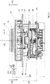
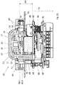
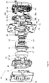
- FIG. 2 the structure of the door lock 200 and the emergency button 10 is shown in more detail.
- the emergency button 10 has a first emergency button processing unit 20, a second emergency button processing unit 21, and a third emergency button processing unit 22.
- the first, second and third emergency button processing units 20, 21, 22 are each designed as microprocessors or microcontrollers.
- the first and second emergency button processing units 20, 21 comprise nonvolatile memory.
- the third emergency button processing unit 22 includes a non-volatile memory and / or has access to a non-volatile memory.
- the first, second and third emergency button processing units 20, 21, 22 are collectively referred to as the electronic unit 24 of the emergency button 10.
- the first emergency button processing unit 20 serves as the first processing unit 103 of the control device 100.
- the second emergency button processing unit 21 serves as the second processing unit 104 of the control device 100.
- the third emergency button processing unit 22 serves as the third processing unit 105 of the control device 100.
- the first and second emergency button processing units 20, 21 serve to execute the safety-related functions of the emergency button.
- the third emergency button processing unit 22 or processing unit 105 is used to execute the non-safety-relevant functions.
- the safety-relevant functions include the cause of unlocking in case of danger.
- Non-safety-related functions include the remaining functions listed above.
- an actuating element 11 Upon actuation of the emergency button 10, an actuating element 11 is moved from an initial position 11.I to an actuation position 11.II, as a result of which a switch 63 is actuated (see also FIG Figures 12 . 13 ). As a result, a first and a second actuation signal are generated. Thereby, a first and a second circuit (not shown) are opened. A signal about the opening of the first circuit is detected by the first emergency button processing unit 20. A signal on the opening of the second circuit is detected by the second emergency button processing unit 21.
- the actuating signal is understood to be the signal generated by the user by the actuation of the actuating element in order to unlock the door lock and to enable the escape route.
- the first emergency button processing unit 20 and the second emergency button processing unit 21 each independently trigger unlocking of the door latch 200 after detecting the operation signal via the first bus system 400.
- the second emergency button processing unit 21 thus acts redundantly to the first emergency button processing unit 20.
- the door lock 200 includes a door lock controller 201.
- the door lock controller 201 includes a first processing means 202 and a second processing means 203.
- the first and second processing means 202, 203 are collectively referred to as an electronic device 207.
- the first and the second processing means 202, 203 are each designed as a microprocessor or microcontroller.
- the first and the second processing means 202, 203 may each control a locking mechanism 205 of the door lock 200 for unlocking.
- d. H As a result of the operation of the emergency button 10 or upon receipt of a fire alarm signal, both the first processing means 202 and the second processing means 203 control the locking mechanism 205 for unlocking.
- the second processing means 203 is thus redundant to the first processing means 202. By this construction, one-error security is achieved.
- the locking mechanism 205 is electromechanically formed.
- the locking mechanism 205 includes z. B. an electromechanically actuated latch member (not shown) which locks a door latch of the door 2 in the locked state of the door lock 200 and releases in the unlocked state of the door lock 200.
- the first and second processing means 202, 203 turn on an electric current to the interlock mechanism 205.
- the first and the second processing means 202, 203 switch off an electric current for the locking mechanism 205.
- a processing means 202, 203 for this purpose a separate switch is assigned. Opening only one of the switches will turn off the power to the latching mechanism 205.
- the door lock controller 201 receives feedback about the state of the lock mechanism 205 via a lock mechanism state monitor, not shown. Specifically, a position of an armature a coil of the locking mechanism 205 monitored. If the state of the door lock 205 does not correspond to the desired state, an alarm is output. Additionally or alternatively, this case can be made a renewed attempt to reach the target state.
- the first and second emergency button processing units 20, 21 communicate with the first and second processing means 202, 203 via the first bus system 400 by means of a message.
- the message may include the message about being actuated or a control command for unlocking.
- the first emergency button processing unit 20 informs the first processing means 202 and the second emergency button processing unit 21 of the second processing means 203.
- the first and second emergency button processing units 20, 21 cause both the first and second processing means 202, 203 to set the lock mechanism 205 to unlock, so turn off the electrical power.
- the presence of a fire alarm signal is detected by the first and second emergency button processing units 20, 21.
- the first and second emergency button processing units 20, 21 cause the locking mechanism 205 to be triggered by the door lock controller 201 by a message to the first and second processing means 202, 203.
- the first emergency button processing unit 20 informs the first processing means 202 and the second emergency button processing unit 21 of the second processing means 203.
- the first and second emergency button processing units 20, 21 cause both the first and second processing means 202, 203 to set the lock mechanism 205 to unlock, so turn off the electrical power.
- the actuation of the emergency button 10 or the presence of a fire alarm signal can be sent in a message from one of the two emergency button processing units 20, 21, the first emergency button processing unit 20 writing a first part of the message and the second emergency button processing unit 21 writing a second part of the message.
- the first and the second processing means 202, 203 are responsible for at least a part of the message.
- the emergency button processing units 20, 21, 22 and the first and second processing means 202, 203 may receive messages via the first bus system 400, respectively.
- the electronic unit 24 and the door lock controller 201 may each be assigned a bus address.
- the first and second emergency button processing units 20, 21 monitor each other. If an error is detected, the electronic unit 24, in particular the intact emergency button processing unit 20, 21, causes the first and the second Processing means 202, 203 control the door lock mechanism 205 for unlocking. The first and second processing means 202, 203 monitor each other. If an error is detected, at least the intact processing means 202, 203 actuates the locking mechanism 205 for unlocking. Also, in case of a failure of the bus system 400, the locking mechanism 205 is driven to release from the door lock controller 201. For this purpose, and for checking the first and second emergency button processing units 20, 21, a sign-of-life signal of the first and second emergency button processing units 20, 21 is regularly sent to the door lock controller 201.
- the locking mechanism 205 is activated for unlocking by the first and the second processing means 202, 203.
- the first and second processing means 202, 203 communicate with each other when the door lock controller 201 has received a message about the operation of the emergency button 10 and / or the presence of a fire alarm signal. If only the first processing means 202 or the second processing means 203 determines that the emergency button 10 has been actuated or a fire alarm signal is present, the determining processing means 202, 203 actuates the door lock mechanism 205 for unlocking and initiates that the other processing means 202, 203 also control the Door lock mechanism 205 activates for unlocking. An error and a fault always include a failure of the respective component.
- the locking mechanism 205 automatically transitions to the unlocked state.
- the security system 1 emits an audible and / or visual alarm, in particular by means of the control device 100.
- the actuation signal When the actuation signal has been generated, it is electronically prevented that the door lock 200 is transferred into the locked state without the presence of a cancellation condition. This prevents the door from being locked while a hazardous condition persists.
- an electronic detection is integrated in the electronic device 207. The electronic detection is converted into an operating state as a result of the actuation of the actuating element 11, which serves to release the escape route. In the operating state, the control of the door lock 200 is prevented for locking.
- the electronic determination comprises a first program code.
- the first program code includes a first variable or has access to a first variable. In an initial state of the electronic determination, the first variable is set to an initial value. In the actuation state, the first variable is set to an actuation value by which the activation of the door lock 200 for Lock is prevented.
- the first variable can be binary.
- the electronic determination is returned to an initial state. For this purpose, the value of the first variable is set to the initial value.
- a control of the door lock 200 is allowed for locking.
- the first program code detects the first value of the first variable and allows latching of the door latch 200 when the value of the first variable is equal to the output value and prevents latching of the door latch 200 when the value of the first variable corresponds to the actuation value.
- the electronic determination is stored both in the first processing means 202 and redundantly in the second processing means 203.
- the first program code is stored in the first processing means 202.
- the first variable is stored in the nonvolatile memory of the first processing means 202.
- a second program code with the same functionality as the first program code is stored in the second processing means 203.
- the first variable is redundantly stored in the nonvolatile memory of the second processing means 203.
- the first variable is additionally stored in the first emergency button processing unit 20 and the second emergency button processing unit 21, respectively, in the non-volatile memories.
- the first variable in the first and second emergency button processing units 20, 21 is transferred from the initial value to the operation value.
- the changed value of the first variable is transmitted to the electronic device 207 via the bus system 400.
- the emergency button 10 repeatedly sends the actuation value of the first variable to the electronic device 207.
- the transmission can take place at regular time intervals, in particular together with the sign of life signal.
- the actuating element 11 is designed non-latching.
- the actuating element 11 is transferred in the actuation of the starting position 11.I in the operating position 11.II (s. FIG. 11 ).
- the actuator 11 moves back to the starting position 11.I by the force of a return spring 12 formed as a spring back (s. FIG. 12 . 13 ).
- the actuation of the actuating element 11 is translational.
- the cancellation action at the emergency button 10 is performed by operating the operation member 11. As a result, a cancellation signal is generated, which corresponds to the actuation signal.
- a further signal must be generated at the same time to achieve the cancellation condition.
- An operator authenticates for this purpose. The authentication is done by inserting and turning a key in the key switch 500. The operation of the actuator 11 and the authentication must overlap in time. Ie. the operator must hold the key in the rotated state while the actuator 11 is in the operating position 11.II. The actuator 11 must return to the home position 11.I while the key is in the rotated state. The course of action is sufficient to achieve the cancellation condition.
- the cancellation condition can be achieved in at least one further manner, namely by elapse of a predetermined time interval. So z. B. after 60 seconds after the last generation of the actuation signal, the cancellation condition be achieved, if the door 2 has remained closed. An authentication on the key switch 500 and a cancellation action on the emergency button 10 are not necessary in this case.
- the first and second door condition monitoring devices 204, 206 are provided to detect, with one-shot security, that the door 2 has remained permanently closed due to the operation of the emergency button 10.
- the door condition monitoring devices 204, 206 are preferably designed differently.
- the first door condition monitor 204 may be e.g. B. be designed as a door contact.
- the second door condition monitor 206 may be e.g. B. be designed as a case contact.
- z. B. at least one of the door condition monitoring magnetically, z. B. as a reed switch, monitor the state of the door 2.
- the door lock controller 201 receives a signal from each of the first and second door condition monitors 204, 206 as to whether the door 2 is open or closed. Only if during the predetermined time interval, neither of the first door condition monitor 204 nor the second door condition monitor 206 has sent a signal on the opening of the door, the cancellation condition can be achieved by elapse of the predetermined time interval.
- the door lock controller 201 includes a timer to measure the predetermined time interval.
- the door lock controller 201 starts the timer in response to the operation of the emergency button 10. If the door lock controller 201 receives a signal from the first or second door condition monitoring device 204, 206 that the door has been opened during the predetermined time interval, a cancellation action must be performed at the emergency button 10. In this case, the elapse of the predetermined time interval is insufficient.
- the length of the predetermined time interval is stored in the door lock controller 201.
- the door lock controller 201 checks whether reaching the cancellation condition by lapse of the predetermined time interval is allowed before the door lock controller 201 drives the lock mechanism 205 to lock.
- an operator during commissioning of the security system d. H. before starting the operation of the security system 1, deposit whether an elapse of the predetermined time interval without opening the door 2 is permissible as a cancellation condition and thus leads to a re-locking of the door 2.
- the deposit can be made in the emergency button 10.
- a check of the permissibility, a lapse of the predetermined time interval, and a lack of a signal from the first and second door state monitors 204, 206 about opening the door 2 is sufficient to achieve the cancellation condition.
- the door lock controller 201 communicates the open or closed state of the door via the bus 400 to the emergency button 10 and / or to the control device 100.
- the electronics unit 24 includes a timer. In the electronics unit 24, a first delay period can be stored. If the door lock 200 is to be unlocked in a time-delayed manner, the electronic unit 24 waits for the first delay time after the generation of the actuation signal before the first and second emergency button processing units 20, 21 communicate with the door lock control 201 via the first bus system 400 to initiate unlocking ,
- the third processing unit 105 causes the FIG. 1 and 2 described non-safety unlocking and locking the door lock 200, z. B. unlocking after receiving the authentication signal, at a predetermined time or after a predetermined period of time or a lock after a predetermined period of time or immediately after closing the door 2.
- the third processing unit 105 via the first bus system 400 with the door lock control 201.
- the communication may, for. B. information or a control command that causes the door lock control 201 to control the locking mechanism for unlocking or locking. If the control device 100 is connected to the second bus system (see FIG. Fig. 7 ), so serves the third processing unit 105 for forwarding messages from and / or to a central escape route control 300.
- the third emergency button processing unit 22 controls the audible alarm generator 23 and the lighting means 41.
- the processing means 202, 203 If at least one of the processing means 202, 203 provides that the locking mechanism 205 has assumed the unlocked state, the processing means 202, 203 sends a corresponding signal via the bus 400 to the electronic unit 24.
- the electronic device 207 is connected to the door condition monitoring device 204, 206 or connectable and receive signals about an open or closed state of the door from the door condition monitors 204, 206.
- control device 100 the door lock control 2021 and / or the emergency button 10 execute are executable with the aid of software modules.
- program codes are stored, by means of which the functions are executable.
- FIG. 3 represents a variant of the in the FIGS. 1 and 2
- the control device 100 is formed separately from the emergency button 10 and the door lock 200.
- the control device 100 may, for. B. in a hat rail housing (not shown) may be arranged.
- the control device 100 is not integrated in an emergency button 10 or in a door lock 200.
- the control device 100 may be provided for placement in a technical room.
- the first bus system 400 connects the control device 100, the door lock 200 and the emergency button 10 with each other.
- the key switch 500 is electrically connected or connectable to the emergency button 10 via a connection 402.
- the structure and the function correspond to the first embodiment, wherein the functions associated with the FIGS. 1 and 2 are described with the aid of the control device 100 or the processing units 103, 104, 105, of the control device 100 of the FIG. 3 be executed and the functions that to the FIGS. 1 and 2 are executed by the emergency button 10.
- the first and second emergency button processing units 20, 21 detect the operation signal, communicate with the first and second buttons as a result of an operation of the emergency button 10 second processing means 202, 203 via the first bus system 400 and thus cause an activation of the locking mechanism 205 by the door lock control 201.
- the measures to achieve on-fail safety and redundancy, respectively, are performed by means of the first and second emergency button processing units 20, 21.
- the first variable is stored in the first and second emergency button processing units 20, 21 and is transmitted from there to the door lock controller 201.
- the emergency button 10 includes the timer for determining the first delay time period.
- the control device 100 is connected or connectable to the second bus system 401.
- the third processing unit 105 causes the FIG. 1 and 2 described non-safety unlocking and locking the door lock 200, z. B. unlocking after receiving the authentication signal, at a predetermined time or after a predetermined period of time or an automatic re-locking after a predetermined period of time or immediately after closing the door. 2
- the first, second and third processing units 103, 104, 105 are each designed as a microprocessor or microcontroller.
- the first, second, and third processing units 103, 104, 105 together constitute processing electronics 101.
- the first and second processing units 103, 104 comprise nonvolatile memory.
- the third processing unit 105 comprises a non-volatile memory and / or has access to a non-volatile memory.
- a fire alarm signal can be received by both the control device 100 and the emergency button 10.
- the presence of a fire alarm signal is detected by the first and the second emergency button processing unit 20, 21 for the emergency button 10 or by the first and the second processing unit 103, 104 for the control device 100.
- both the control device 100 with the aid of the first and the second processing unit 103, 104 and the emergency button 10 with the aid of the first and the second emergency button processing unit 20, 21 can cause an unlocking of the door lock 200.
- communication takes place via the first bus system 400 with the door lock control 201.
- the control device 100 is informed via the first bus system 400 when the emergency button 10 causes an unlocking of the door lock 200, that is, as a result of an actuation of the emergency button 10 or after receiving a fire alarm signal.
- the control device 100 is also informed about a time-delayed unlocking of the door lock 200 as a result of the operation of the emergency button 10.
- the control device 100 is informed of the locking and unlocking state of the door latch 200.
- the control device 100 is informed of the open or closed state of the door 2.
- the control device 100 causes a triggering of the alarm transmitter 23 and the lighting means 41 for the to FIGS. 1 and 2 described acoustic alarms and optical representations.
- the control device 100 can communicate with the electronic unit 24, in particular with the third emergency button processing unit 22, via the first bus system 400.
- the third emergency button processing unit 22 then controls the alarm transmitter 23 or the lighting means 41.
- the parameters for the alarm transmitter 23 and the lighting means 41 are stored in the control device 100.
- Door lock 200 includes door status monitors 204, 206.
- door status monitors 204, 206 may be connected to first bus system 400 or directly to emergency button 10 and / or controller 100.
- At least one further emergency button may be connected to the first bus system 400, which is designed without the control device 100.
- the other emergency button is like the emergency button 10 in FIG. 3 trained and can cause the unlocking of the door lock 200 when actuated.
- the further emergency button corresponds in structure and functionality to the emergency button 10 of the FIG. 3 ,
- At least one further door lock may be connected to the first bus system 400.
- the further door lock is like the door lock 200 in FIG. 2 or 3 trained and can also be unlocked upon actuation of the emergency button 10.
- the further door lock corresponds in structure and in the functionality of the door locks 200 of FIGS. 1 to 3 ,
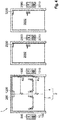
- FIG. 4 a third embodiment of a security system 1 according to the invention with multiple emergency buttons 10, 1010, 2010, 3010 is shown.
- the security system 1 comprises a plurality of door locks 200, 1200, 2200, 3200.
- Each emergency button 10, 1010, 2010, 3010 is assigned a key switch 500, 1500, 2500, 3500.
- the safety system 1 serves to arrange the emergency buttons 10, 1010, 2010, 3010 and door locks 200, 1200, 2200, 3200 on different doors 2, 2002, 3002.
- the doors 2, 2002, 3002 are not part of the security system 1 according to the invention
- Emergency buttons 10, 1010, 2010, 3010 are connected to the first bus system 400 and thus correspond to a number of emergency buttons 10, 1010, 2010, 3010.
- the door locks 200, 1200, 2200, 3200 are connected to the first bus system 400 and correspond to one Number of door locks 200, 1200, 2200, 3200.
- the emergency buttons 10, 1010 are associated with the door locks 200, 1200.
- the emergency button 2010 is assigned to the door lock 2200.
- Emergency button 3010 is associated with door lock 3200.
- the two door locks 200, 1200 unlocked, but not the door locks 2200, 3200. If the emergency button is pressed in 2010, only the door lock 2200 is unlocked. Accordingly, when the emergency button 3010 is operated, only the door latch 3200 is unlocked.
- the door locks 200, 1200, 2200, 3200 are selectively unlocked.
- the emergency buttons 10, 1010 may be provided for placement on a two-leaf door 2.
- a door lock 200, 1200 is to be arranged in each case on a door leaf 3, 4 of the door 2.
- the emergency button 2010 and the door lock 2200 are provided to be arranged on another door 2002.
- the emergency button 3020 and the door latch 3200 are to be arranged on a door 3002 as in FIG FIG. 4 shown.
- the security system 1 off FIG. 4 can also for from FIG. 4 deviating selective unlocking be adjustable.
- At one too FIG. 4 deviating example setting is only one associated door lock 200, 1200, 2200, 3200 unlocked upon actuation of one of the emergency button 10,1010, 2010, 3010 respectively.
- one emergency button 10, 1010, 2010, 3010 is assigned in each case only one door lock 200, 1200, 2200, 3200.
- the security system 1 is suitable for two double-leaf doors, each with a door lock 200, 1200, 2200, 3200 per door leaf.
- the security system 1 can be set so that upon actuation of an emergency button 10, 1010, 2010, 3010 all door locks 200, 1200, 2200, 3200 are unlocked.
- a security system 1 may comprise a number of emergency buttons 10, 1010, 2010, 3010, which does not coincide with the number of door locks 200, 1200, 2200, 3200.
- the door 2 is designed to be single-winged and one of the emergency buttons 10, 1010 or one of the door locks 200, 1200 is missing.
- FIG. 5 It is shown that the emergency buttons 10, 1010, 2010, 3010 and the door locks 200, 1200, 2200, 3200 are connected to each other via the first bus system 400.
- Each an emergency button 10, 1010, 2010, 3010 is electrically connected or connectable to a key switch 500, 1500, 2500, 3500 assigned to the respective emergency button 10, 1010, 2010, 3010 via a connection 402, 1402, 2402 or 3402.
- the key switches 500, 1500, 2500, 3500 are connected to the first bus system 400 (not shown).
- the first bus system 400 is connected to only a single controller 100.
- the structure and functions of the door locks 200, 1200, 2200, 3200 correspond to the structure and functions of the door lock 200 of Figures 2 and 3
- the structure and functions of the emergency button 10 the construction and functions of the emergency button 10 of FIG. 2 and the structure and functions of the emergency button 1010, 2010, 3010 the structure and functions of the emergency button 10 of FIG. 3
- the reference numerals from the Figures 2 and 3 are used. It is understood that each of the door locks 200, 1200, 2200, 3200 include its own door locking mechanism, own processing means, etc. and the emergency buttons 10, 1010, 2010, 3010 each own emergency button processing units, alarm, bulbs, switches and actuators.
- the assignment of emergency buttons 10, 1010, 2010, 3010 can be done to the door locks 200, 1200, 2200, 3200, when commissioning the security system 1, ie before the start of operation of the security system 1, an assignment of emergency buttons 10, 1010 , 2010, 3010 made to the door locks 200, 1200, 2200, 3200.
- one of the door locks 200, 1200, 2200, 3200 is in each case transferred to an assignment mode.
- a deliberate action is taken at the emergency buttons 10, 1010, 2010, 3010.
- the conscious action may be carried out as an actuation of the actuating element 11 of the respective emergency button 10, 1010, 2010, 3010.
- the interlocking mode of the door interlock 200, 1200, 2200, 3200 is ended.
- z. B first transferred the door lock 200 in the assignment mode and then the emergency button 10, 1010 operated, whereby the assignment of the emergency button 10, 1010 to the door lock 200 is carried out. Then, the assignment mode of the door lock 200 is ended. Subsequently, z. B. the door lock 1200 transferred to the assignment mode and then the emergency button 10, 1010 operated, whereby the assignment of the emergency button 10, 1010 to the door lock 1200 is carried out. Then, the assignment mode of the door lock 1200 is ended. Now the door lock 2200 is transferred to the assignment mode and then the emergency button 2010 is actuated, whereby the assignment of the emergency button 2010 to the door lock 2200 takes place.
- the assignment mode of the door lock 2200 is ended. Accordingly, it can then be moved with the door lock 3200 and the emergency button 3010.
- the assignment of the assignment in the respective door interlocks 200, 1200, 2200, 3200 takes place respectively in the first digital processing means 202 and redundantly in the second digital processing means 203, in particular in the non-volatile memories of the processing means 202, 203.
- the emergency button 10 communicates with all door locks 200, 1200, 2200, 3200 of the first bus system 400.
- the door locks 200, 1200, 2200, 3200 check each based on the deposit, whether the respective door lock 200, 1200, 2200, 3200 has been assigned to the actuated emergency button 10. Only in the case of the assignment then control the associated door locks 200, 1200 to the respective door lock mechanism 205.
- the door locks 200, 1200, 2200, 3200 which are assigned to the fire alarm signal receiving emergency button 10, 1010, 2010, 3010, unlocked.
- a first delay time period is stored in that emergency button 10, 1010, 2010, 3010.
- the deposit takes place when the safety system 1 is commissioned by the parameterization program.
- a different first delay time period can be stored by the operator.
- the emergency button 10 stores a first delay time period, which differs from the first delay time duration, which is stored in the emergency button 2010.
- the emergency buttons 1010, 3010 are to initiate a release of the associated door locks 2200 and 3200 without delay, so that in the emergency buttons 1010, 3010 no first delay period or a first delay period of 0 s is stored.
- the security system 1 may be designed such that in the emergency buttons 10, 1010, 2010, 3010, the same door lock 200, 1200, 2200, 3200 are assigned, always the same first delay time period is stored.
- the parameterization program allows the operator only a common setting.
- the control device 100 takes over the non-safety-relevant functions for unlocking and locking all door locks 200, 1200, 2200, 3200, as previously FIG. 1 and 2 described.
- the control device 100 with the door locks 200, 1200, 2200, 3200 selectively communicate.
- the control device 100 is deposited, which access control system which door lock 200, 1200, 2200, 3200 is assigned, so that when a positive authentication signal of an access control system only the associated (s) door lock (s) 200, 1200, 2200, 3200 are unlocked. It is also stored in the control device 100, if and when yes, which door lock 200, 1200, 2200, 3200 is to be unlocked at what predetermined time.
- the deposits may be made differently for each door latch 200, 1200, 2200, 3200 or for the groups of door locks 200, 1200, 2200, 3200 to be arranged on a door 2, 2002, 3002.
- the deposit is made with the aid of the parameterization program by the operator during commissioning.
- the control device 100 causes an acoustic and visual alarm as a result of the operation of a emergency button 10, 1010, 2010, 3010 is also output in the at least one further emergency button 10, 1010, 2010, 3010, the same door lock 200, 1200, 2200, 3200 as the actuated emergency button 10, 1010, 2010, 3010 is assigned. Is in the embodiment of FIGS. 4 and 5 z. B. the emergency button 10 is actuated, the control device 100 causes by communication with the electronics unit 24 of the emergency button 1010 that the acoustic alarm generator 23 and the bulbs 41 of the emergency button 1010 issue an audible or visual alarm.
- the control device 100 causes the first delay period with which the unlocking is initiated to occur in the at least one further emergency button 10, 1010, 2010, 3010 which is associated with the same door lock 200, 1200, 2200, 3200 as the operated emergency button 10, 1010, 2010, 3010.
- the control device 100 communicates with the electronics unit 24 of the at least one further emergency button 1010, 2010, 3010 or controls the lighting means 41 of the emergency button 10, in which the control device 100 is integrated.
- the control device 100 may be the non-safety-related assignment for selective communication, for. B. the assignment of an access control system to a door lock 200, 1200, 2200, 3200 make a bus address.
- the subscribers of the first bus system 400 each have an adjustment device for the manual setting of a bus address.
- the adjustment device may include DIP switches. At least the users of the first bus system 400 who have the same setting on the setting device are automatically assigned to each other. In order to be able to assign different bus addresses to subscribers with the same setting, subscribers of the first bus system 400 have different key figures from which different bus addresses are configured with the aid of the setting made.
- the bus address detected by means of the setting is for the emergency buttons 10, 1010, 2010, 3010 and for the door locks 200, 1200, 2200, 3200, only one more bus address which the emergency buttons 10, 1010, 2010, 3010 and Use the door interlocks 200, 1200, 2200, 3200 next to the bus address used in safety-related communication.
- the control device 100 can prevent an unlocking of a further door lock 200, 1200, 2200, 3200 until a condition is present, provided that no danger exists. If the condition is met, the control device 100 causes the unlocking of the further door lock 200, 1200, 2200, 3200. In this way, the control device 100 with a plurality of door locks 200, 1200, 2200, 3200 communicate so that a lock is formed.
- the door 2002 may be located at an entrance to a room and the door 3002 may be located at an exit of the same room.
- the controller 100 may cause the door latch 2200 to unlock upon the presence of a positive door latch 2200 authentication signal.
- the control device 100 can prevent the unlocking of the door lock 3200 until a condition exists. If the condition is present, then the control device 100 causes an unlocking of the door lock 3200.
- the condition may be, for. B. at a lock time interval or Reaching a measured variable, such as room temperature, air humidity, air purity or number of people in the room, act.
- the control device 100 can be connected to a measuring device or connectable.
- the condition may include closing the first opened door 2002, which is measurable by the door condition monitors 204, 206.
- the condition and the door locks 2200, 3200 involved in the lock can be stored in the control device 100. The deposit can be made by the operator using the parameterization program.
- FIG. 6 is a variant of the in the FIGS. 4 and 5 shown security system 1 shown.
- the control device 100 is formed separately from the emergency buttons 10, 1010, 2010, 3010 and the door locks 200, 1200, 2200, 3200.
- the first bus system 400 connects the control device 100 to the door locks 200, 1200, 2200, 3200 and the emergency buttons 10, 1010, 2010, 3010.
- the control device 100 of FIG. 6 corresponds in structure to the control device 100 of FIG. 3
- the emergency button 10 of the FIG. 6 corresponds in construction to the emergency button 10 of the FIG. 3
- the structure and the functionalities previously agreed FIG. 5 are described, the structure and the functionalities of the security system 1 of FIG. 6 ,
- the door locks 200, 1200, 2200, 3200, the emergency buttons 10, 1010, 2010, 3010 and possibly the control device 100 act as subscribers of a single first bus system 400, only the cables of the bus system 400 are necessary so that the participants can communicate with each other.
- the security system 1 has only a few cables.
- the bus system 400 may include at least two cables for communication and at least two cables for power.
- the bus system 400 has exactly two cables for communication and two cables for the power supply.
- a power supply can be integrated as a connection to a power grid at any point of the bus system 400.
- the power supply can be provided as an independent component of the security system 1 outside the emergency button 10 or the emergency button 10, 1010, 2010, 3010 and the door lock 200 and the door locks 200, 1200, 2200, 3200.
- the security system 1 in the physical structure is flexible.
- the electronic button only prevents the electronic button 10 from being actuated. 1010, 2010, 3010 associated door locks 200, 1200, 2200, 3200 are locked. Achieving the cancellation condition allows the locking of the door lock (s) 200 associated with the actuated emergency button 10, 1010, 2010, 3010, 1200, 2200, 3200. To achieve the cancellation condition, the time-overlapping operation of the actuator 11 of the emergency button 10, 1010, 2010, 3010, which was previously operated, and the authentication on the key button associated with the actuated emergency button 10, 1010, 2010, 3010 500, 1500, 2500, 3500 necessary.
- At least this action sequence is necessary for the door lock 200, 1200, 2200, 3200 associated with the actuated emergency button 10, 1010, 2010, 3010, in which at least one of the door condition monitoring devices 204, 206 has detected that the door 2 or one of the door leaves 3, 4 was opened after pressing the emergency button 10.
- the cancellation condition can be achieved by the lapse of the predetermined time interval.
- the cancellation condition z. B. be reached after 60 seconds after the last operation of the emergency button 10.
- the deposit can z. B. in the emergency windows 10, 1010, 2010, 3010 done.
- the length of the predetermined time interval can be individually adjustable. This can be a minimum length, z. B. 60 s, be predetermined for the predetermined time interval.
- the deposit is made by the parameterization program.
- FIG. 7 a fifth embodiment of the security system 1 according to the invention is shown.
- the fifth embodiment includes the security system 1 according to the first embodiment of the FIGS. 1 and 2 , That is, the emergency button 10 including the control device 100 is connected to the door latch 200 via the bus system 400.
- the key switch 500 is connected via a connection 402 with the emergency button 10 or connectable.
- further components 300, 301, 510 are provided in comparison with the first exemplary embodiment.
- the security system 1 includes the central escape route controller 300.
- the central escape route controller 300 is provided to be located remotely from the door 2.
- the central escape route control 300 z. B. together with a watch device 301, which may be configured as a monitor or personal computer, and / or a Multi-door indicator 350 (s. Fig. 10 ) to be arranged in a guardroom.
- the watch device 301 is optionally part of the security system 1 according to the invention.
- the watch device 301 can be connectable to the security system 1 according to the invention.
- the central escape route control 300 has a modular structure.
- An emergency module 310 includes a first attachment plate 311.
- the first attachment plate 311 receives a central emergency button 302 and an identification device 312 exemplified as a key switch.
- the central emergency pushbutton 302 and the identification device 312 are mechanically rigidly connected to one another.
- the central emergency button 302 serves to unlock the door lock 200 as a result of actuation of the central emergency button 302.
- the central emergency button 302 away from the door 2 the door latch 200 can be unlocked.
- the unlocking as a result of the operation of the central emergency button 302 is done with a one-fault security.
- the operation of the central emergency button 302 is thus suitable for the danger.
- a deactivation module 320 comprises a first control element 322 embodied as a key pushbutton and a second control element 323 configured as a pushbutton.
- the first control element 322 serves to deactivate the emergency pushbutton 10.
- the emergency pushbutton 10 is deactivated Condition convicted. If the emergency button 10 is in a deactivated state, an unlocking of the door lock 200 is omitted as a result of an actuation of the emergency button 10.
- the second operating element 323 serves to activate the emergency button 10.
- the emergency button 10 is in the deactivated state and becomes the second operating element Pressed 323, the emergency button 10 is transferred to an activated state.
- the deactivation module comprises a second mounting plate 321.
- the second mounting plate 321 serves to receive the first and the second operating element 322, 323.
- the second mounting plate 321 connects the first and the second operating element 322, 323 mechanically rigidly together.
- a retardation module 330 includes a third attachment plate 331.
- the third attachment plate 331 receives a retardation element 332.
- the delay element 332 is exemplified as a key switch.
- the delay element 332 serves to further delay the unlocking of the door lock 200 within the first delay duration.
- the delay module 330 includes a termination element 333, which is designed as a button.
- the termination member 333 is attached to the third attachment plate 331.
- the termination element 333 is by means of the third Fixing plate 331 mechanically rigidly connected to the delay element 332.
- the central escape route controller 300 includes a one-way open escape route control housing 340 in which the emergency module 310, the deactivation module 320, and the delay module 330 are disposed.
- the deactivation module 320 and the delay module 330 are optional components of the central escape route safety device 300.
- the multi-door display device 350 can also be arranged.
- the escape route control enclosure 340 may mechanically secure the emergency module 310, the deactivation module 320, and the delay module 330.
- the emergency module 310, the deactivation module 320 and the delay module 330 are each individually secured to the escape route control housing 340, in particular screwed.
- For attachment to the escape route control housing 340 serve the first mounting plate 311 for the emergency module 310, the second mounting plate 321 for the deactivation module 320 and / or the third mounting plate 331 for the delay module 330.
- the escape route control housing 340 and the modules 310, 320, 330 are configured such that various sequences in which the modules 310, 320, 330 can be arranged next to one another are possible. So z. B.
- a central emergency exit device 300 not shown, for.
- the emergency module 310 may be located between the deactivation module 320 and the delay module 330.
- exemplary central escape route control 300 a free space, delay module 330 in the middle and emergency module 310 on the right can be arranged on the left. The clearance is due to the absence of the deactivation module 320 and is hidden by a plate.
- the escape route control housing 340 may include rails for inserting the modules 310, 320, 330.
- the escape route control housing 340 may have attachment options, e.g. As perforated strips or slots, for variable attachment of the module 310, 320, 330 have.
- a purely schematically illustrated display area 314, 324 and 334 is provided on the first mounting plate 311, on the second mounting plate 321 and on the third mounting plate 331.
- optical lights for indicating states of the security system 1 in the display areas 314, 324, 334 may be provided.
- the security system 1 further includes an audio and video module 510.
- the audio and video module 510 is located near the door for placement 2, which can be locked by the door latch 200 provided. If the audio and video module 510 is unlocked, an operator in the guardroom can speak with the user in front of the door 2 and view the room near the door 2.
- the central emergency button 302 similar to the emergency button 10 is constructed.
- the central emergency button 302 includes an emergency button electronics unit 308.
- the emergency button electronics unit 308 includes a first emergency processing unit 303, a second emergency processing unit 304 and a third emergency processing unit 305.
- the first, second and third emergency processing units 303, 304, 305 are each configured as a microprocessor or microcontroller.
- the first and second emergency processing units 303, 304 comprise nonvolatile memory.
- the third emergency processing unit 305 has a non-volatile memory and / or has access to a non-volatile memory.
- the central emergency button 302 is actuated by actuating an emergency button actuator 306.
- a Notfalltasterschalter 307 is actuated.
- a first and a second signal are generated.
- a first and a second circuit (not shown) are opened.
- a signal on the opening of the first circuit is detected by the first emergency processing unit 303.
- a signal on the opening of the second circuit is detected by the second emergency processing unit 304.
- the central emergency button 302 is connected to a second bus system 401. As in FIG. 9 As shown, the control device 100 is also connected to the second bus system 401.
- the second bus system 401 is a different type of bus system than the first bus system 400.
- the second bus system 401 may be configured as a LON or LAN bus and the first bus system 400 as a CAN or DCW bus.
- the emergency button 10 comprises the control device 100.
- the emergency button 10 and the door latch 200, which in FIG. 9 are mapped correspond to the emergency button 10 and the door lock 200 of FIG. 2 ,
- control device 100, the emergency button 10 and the door lock 200 according to the FIG. 3 educated.
- control device 100, the emergency button 10 and the door lock 200 are connected to each other via the first bus system 400, wherein the control device 100 is connected to the second bus system 401.
- the control device 100 receives messages from the central escape route safety device 300 via the second bus system 401.
- the control device 100 forwards the messages to other subscribers of the first bus system 400 via the first bus system.
- the message may contain information relating to an actuation of the central Emergency button 302, the key switch 312, the first control element 322, the second control element 323, the delay element 332 and / or the termination element 333 or a control command in response to an actuation of one of the aforementioned elements 302, 312, 322, 323, 332, 333 , If the control device 100 is integrated in the emergency button 10, a forwarding to the emergency button 10, in which the control device 100 is integrated, is dispensed with. For example, conducts according to the FIG.
- the controller 100 forwards the message to the door latch 200. If the control device 100 and the emergency button 10 are connected via the first bus system 400, then the control device 100 forwards the message to the emergency button 10 and / or the door lock 200. The controller 100 adapts the message to the format of the first bus system 400. Security-relevant messages are otherwise left untouched.
- the central emergency button 302 If the central emergency button 302 has been actuated, then the first emergency processing unit 303 and redundantly the second emergency processing unit 304 unlock the door lock 200. In this case, the central emergency button 302 communicates with the door lock control 201, in particular the first and the second processing means 202, via the control device 100. 203. The first and second processing means 202, 203 then control the locking mechanism 205. Previously, the first and second processing units 103, 104 forwarded the message. Here, the control device 100 has left the content of the message untouched.
- the central emergency button 302 has an input for receiving a fire alarm signal. When the fire alarm signal is received, the central emergency push button 302 causes the door lock 200 to be unlocked.
- the first and second emergency processing units 303, 304 communicate with the door lock control 201 via the control device 100, namely via the first and second processing units 103, 104. Like previously described.
- a signal via an actuation of the key switch 312 of the first module 310 is received by the emergency button electronics unit 308, in particular the third emergency processing unit 305.
- the emergency button electronics unit 308 sends a message regarding the operation of the key switch 312 via the second bus system 401 to the control device 100.
- the control device 100 forwards the message to the first bus system 400.
- the emergency button actuator 306 is non-latching.
- the emergency button actuating element 306 is identical to the actuating element 11 of the emergency button 10 (see FIG. FIGS. 13 to 15 ).
- the emergency operating member 306 becomes on actuation from an initial position to an actuated position (analog FIG. 11 ).
- the emergency operating member 306 moves back to the initial position by the force of a return means formed as a spring (analog FIG. 11 ).
- the actuation of the emergency operating element 306 is translational. If, as a result of actuation of the central emergency button 302, the door lock 200 is transferred into the unlocked state, the electronic device 207 prevents the door lock 200 from being returned to the locked state without the existence of a cancellation condition.
- the cancellation condition after actuation of the central emergency button 302 can be achieved by operating the key switch 312. In particular, an actuation of the key switch 312 is sufficient to achieve the cancellation condition.
- the cancellation condition can be reached in a further manner as a result of an actuation of the emergency button 10. If the door state monitoring devices 204, 206 have detected that the door 2 has remained permanently closed after the emergency button 10 has been actuated is, the cancellation condition can be achieved by elapse of a predetermined time interval and a cancellation treatment at the central escape route controller 300 after the predetermined time interval.
- the cancellation treatment may correspond to an authentication at the central escape route controller 300, in particular an actuation of the key switch 312. By the Aufhe abstraction, z. As the operation of the key switch 312, a Aufhebesignal is generated.
- the cancel signal is forwarded to the door lock controller 201 via the control device 100. An authentication on the key switch 500 and a cancellation action on the emergency button 10 are not necessary in this case.
- the door lock controller 201 checks whether reaching the canceling condition by passing the predetermined time interval and authenticating to the central escape route controller 300 with the door 2 kept closed is allowed before the door lock controller 201 drives the lock mechanism 205 to lock. Thus, an operator during the commissioning of the security system 1 deposit whether a lapse of the predetermined time interval without opening the door 2 and the additional operation of the key switch 312 is permitted as a cancellation condition and thus leads to a re-locking of the door 2.
- This variant can z. B. be selected by the operator, if only the lapse of the predetermined time interval remains closed with the door 2 the operator not sure enough. The operator can select and save this variant by means of the parameterization program.
- the elapse of the predetermined time interval with the door 2 closed is visually displayed on the central escape route controller 300.
- the lighting means 313 are for indicating that the predetermined time interval has elapsed without receiving a signal on the opening of the door 2 within the predetermined time interval.
- the visual display tells the operator that the door 2 can be locked by authentication to the central escape route controller 300.
- the door lock 200 can also be locked by the same operation of the key switch 312. Also, the possibility to achieve locking of the door lock 200 by actuating the key switch 312 after termination of the fire alarm signal is optically indicated by the lighting means 313.
- the control device 100 forwards messages from the emergency button 10 and / or the door lock 200 via the second bus system 401.
- the control device 100 adjusts the message to the format of the second bus system 401.
- the control device 100 sends information about the state of the emergency button 10 and / or the door lock 200 via the second bus system 401.
- the central escape route controller 300 and the multi-door display device 350 may be connected to a third bus system 403 (see FIG. Fig. 10 ).
- the multi-door indicator 350 can visually indicate the locking and unlocking state of the door lock 200.
- one of the door locks 200, 200 ', 1200', 2200 'of the security system 1 are unlocked. Unlocking with the help of the multi-door indicator 350 is not one-error-safe.
- the third bus system 403 may be the same type of bus system as in the first bus system 400, z. B. to a CAN or DCW bus.
- the control device 100 forwards via the second bus system 401 to the central escape route controller 300 when the emergency button 10 waits a first delay period before the emergency button 10 causes the door lock controller 201 to actuate the lock mechanism 205 for unlocking.
- the first delay time period is visually displayed at the central escape route controller 300.
- the central emergency button 302 is constructed according to the emergency button 10, as it is the Figures 13 . 16, 17 is described.
- the lighting means 313 of the central emergency button 302 are actuated by the emergency button electronic unit 308. With the progress of the first delay period, less bulbs 313 in the same color light up. For example, fewer bulbs 313 in a first color and increasingly many bulbs 313 in a second color may shine.
- the lighting means 41 of the emergency button 10 are driven in an identical manner to optically represent the first delay time period.
- the operator can actuate the delay element 332.
- the operator turns a key in the key switch, which serves as a delay element 332.
- An actuation of the delay element 332 is detected by the emergency button electronics unit 308, in particular the third emergency processing unit 305.
- a corresponding message is sent via the second bus system 401 and possibly the first bus system 400.
- the emergency button 10 receives the message.
- the emergency button 10 terminates the first delay time period and starts with a second delay time period.
- the second delay period e.g. B. 180 s, is longer than the first delay period.
- the emergency button 10 initiates the unlocking of the door lock 200.
- the second delay time period is determined in the emergency button 10 by means of the same timer used to determine the first delay time period.
- the key of the delay element 322 need not remain rotated. Rather, a single turn of the key is sufficient to start the second delay period.
- the second delay time period is visualized at the central escape route controller 300 and at the emergency button 10.
- the visual representation at the central escape route control 300 is similar to the visual display at the emergency button 10.
- fewer bulbs 41, 313 are illuminated in the same color.
- fewer lamps 41, 313 in a first color and increasingly many lamps 41, 313 are illuminated in a second color.
- a time lapse pattern may be repetitively added within the second delay time period, e.g. B. a circumferential color point or a circumferential color window (see description to FIG. 16, 17 ) are visually displayed.
- the emergency electronics unit 308 detects the actuation of the termination element 333 and sends a message regarding the actuation of the termination element 333 via the second bus system 401. This causes the emergency electronics unit to initiate 308 the emergency button 10 not to delay the unlocking, but to cause immediate unlocking the Matverrieglung 200.
- the termination element 333 is non-latching. A single actuation of the termination element 333 is sufficient to complete the delay of the initiation of the unlocking.
- the emergency button 10 can be transferred by an operation of the first control element 322 in the deactivated state.
- the operator turns a key in the key switch, which serves as a first operating element 322.
- Actuation of the first operating element 322 is detected by the emergency button electronics unit 308.
- a first and a second deactivation circuit are opened or closed.
- the opening or closing of the first deactivation circuit is detected by the first emergency processing unit 303.
- the opening or closing of the second deactivation circuit is detected by the second emergency processing unit 304.
- the first and the second emergency processing units 303, 304 communicate with the emergency button 10 via the second bus system 401. If the first bus system 400 is located between the emergency button 10 and the central emergency button 302, the control device 100 sends the message to the first and the second emergency processing unit 303 , 304 continue. When forwarding, the format is changed, but the content remains unchanged.
- the activated state and the deactivated state are stored electronically in the emergency button 10.
- the key in the first control 322 need not remain rotated during the disabled state. Rather, a single turn of the key is sufficient to disable the emergency button 10.
- the deactivation remains until the second operating element 323 is actuated.
- the actuation of the second operating element 323 can be detected by the emergency button electronic unit 308, in particular the third emergency processing unit 305.
- the emergency electronics unit 308 sends a message regarding the actuation of the second operating element 323 via the second bus system 401 and optionally via the first bus system 400 to the emergency button 10, whereupon the emergency button 10 is transferred to the activated state.
- the second control 323 is not latching. Characterized in that the activated and the deactivated state is stored in the emergency button 10, a single actuation of the second operating element 323 is sufficient to bring the emergency button 10 in the activated state.
- the central escape route control 300 comprises a bus 341, via which the emergency electronics unit 308, in particular the third emergency processing unit 305, can detect signals of the second operating element 323, the delay element 332 and the termination element 333.
- the emergency electronic unit 308 serves as the intelligence of the entire central escape route controller 300. Only the emergency electronic unit 308 includes microprocessors.
- the deactivation module 320 and / or the delay module 322 may be configured processor-free.
- the bus 341 may be configured as an I 2 C bus.
- a second variable can be stored in the first emergency button processing unit 20 and redundantly in the second emergency button processing unit 21, in particular in the non-volatile memories.
- the second variable can be binary. If the emergency button 10 is in the deactivated state, then the second variable is set to a deactivation value. If the emergency button 10 is in the activated state, the second variable is set to an activation value. As a result of an actuation of the first operating element 322, the second variable is set to the deactivation value. As a result of an actuation of the second operating element 323, the second variable is set to the activation value.
- the emergency button 10 checks the value of the second variable. If the emergency button detects that the emergency button 10 is deactivated, a communication of the emergency button 10 with the door lock control 201 is prevented in order to cause an unlocking 200.
- the first emergency processing unit 303 and the second emergency processing unit 304 mutually monitor for errors. If an error is detected, a message is sent via the second bus system 401.
- the emergency button 10 receives the message and then transfers itself to the activated state if the emergency button 10 is in the disabled state is located. For this purpose, the emergency button 10 changes the value of the second variable to the activation value.
- the first emergency processing unit 303 and the second emergency processing unit 304 repeatedly, in particular at regular intervals, send a sign of life signal via the second bus system 401.
- the emergency button 10 receives the sign of life signals. Leaves a sign of life signal once or several times, then the emergency button 10 is transferred to the activated state, if the emergency button 10 is in the deactivated state.
- the emergency button 10 transfers to the activated state if the emergency button 10 is in the deactivated state.
- the operation of the emergency button 10 in the deactivated state is displayed on the central escape route controller 300, on the watch device 301 and / or on the multi-door display device 350. If a danger situation actually exists, then the emergency button 10 can be converted by the operator into the activated state by the operator actuating the second operating element 323, or the door lock can be directly actuated by the operator for unlocking. For this purpose, the operator can actuate the central emergency button 302. Whether a hazard exists, the operator z. B. perceive via the audio and video module 510. As a result, increased security is achieved.
- the deactivation can z. B. be made at night in a department store. Furthermore, it is conceivable to use the deactivatable emergency button 10 in a building in which people with an impaired state of mind live. Emergency buttons 10 can also be used on doors accessible to people with impaired mental state, eg. On a psychiatry or dementia ward.
- the emergency button 10 If the emergency button 10 is actuated in the deactivated state and then the emergency button 10 is transferred to the activated state, the emergency button 10 which has been actuated in the deactivated state does not lead to unlocking of the door lock 200 even after the transfer to the activated state deactivated state, operation of the emergency button 10 remains ineffective. This is due, on the one hand, to the fact that the actuating element 11 and the switch 63 are non-latching. On the other hand, the operation of the emergency button 10 was not stored in the disabled state 10 in the disabled state. The door lock controller 201 receives no message regarding the operation of the emergency button 10 in the deactivated state. The electronic detection was therefore not transferred to the operating state. This ensures that not directly with the activation of the emergency button 10, the door lock 100 is unlocked, z. B. because long before the emergency button 10 was pressed. As a result, an increased building security is achieved.
- the audio and video module 510 In order to achieve a particularly high level of security, provision can be made for the audio and video module 510 to be switched on during the first and / or the second delay time period.
- the emergency button 10 releases the audio and video module 510 at the beginning of the first and / or second delay period.
- the audio and video module 510 is enabled by the emergency button 10 when the emergency button 10 is operated in the disabled state.
- the emergency button 10 communicates via the second bus system 401 and optionally via the first bus system 400 with the audio and video module 510.
- the emergency button 10 is only deactivated when the audio and video module 510 is unlockable. If the audio and video module 510 part of the security system 1 according to the invention, then a deactivation can be omitted if the audio and video module 510 z. B. is not functional and / or the connection to the audio and video module 510 is disturbed. This does not apply if the security system 1 does not comprise an audio and video module 510, but a monitoring system separate from the security system 1 is provided in the building.
- the emergency button 10 delays the cause of the unlocking only by the first and / or second delay time period when the audio and video module 510 is unlockable. If the audio and video module 510 part of the security system 1 according to the invention, then a delay can be omitted if the audio and video module 510 z. B. is not functional and / or the connection to the audio and video module is disturbed. This does not apply if the security system 1 does not comprise an audio and video module 510, but a monitoring system separate from the security system 1 is provided in the building.
- FIG. 10 a further embodiment of a security system 1 according to the invention is shown.
- the security system 1 comprises a central escape route controller 300, which operates according to the FIGS. 7 and 8th is constructed. Key buttons 500, 500 ', 1500, 1500', 2500 associated with the respective emergency buttons 10, 10 ', 1010, 1010', 2010 are not shown for the sake of clarity.
- the central escape route controller 300 is connected to the second bus system 401. To the second bus system 401, a first subsystem 5 and a second subsystem 6 are connected.
- the two subsystems 5, 6 each comprise a first bus system 400, 400 '.
- Emergency buttons 10, 1010 and 10 ', 1010', 2010 'and door locks 200 and 200', 1200 ', 2200' are respectively connected to the respective first bus system 400, 400 '.
- the first bus systems 400, 400 ' are the same bus system type, eg. B. order a CAN or a DCW bus.
- the second bus system 401 is another type of bus system, e.g. B. a LON or LAN bus.
- the security system 1 comprises the multi-door display device 350.
- the multi-door display device 350 may e.g. B. visually indicate which door lock 200 or 200 ', 1200', 2200 'is in the unlocked state and which door lock is in the unlocked state. With the aid of the multi-door display device 350, an operator can perform a non-safety-relevant locking and unlocking of individual door locks 200 or 200 ', 1200', 2200 'of the security system 1.
- Each subsystem 5, 6 comprises only one control device 100, 100 '.
- the control device 100, 100 'of the respective subsystem 5, 6 is connected to the second bus system 401.
- the control device 100 of the first subsystem 5 is connected to the emergency buttons 10, 1010 and the door lock 200 of the first subsystem 5 via the first bus system 400.
- the control device 100 'of the second subsystem 6 is integrated in an emergency button 10' of the second subsystem 6 and connected to the remaining emergency buttons 1010 ', 2010' and the door locks 200 ', 1200', 2200 'of the further first bus system 400'.
- a first emergency button 10 and a second emergency button 1010 are provided. If one of the emergency buttons 10, 1010 is actuated, then the actuated emergency button 10, 1010 respectively causes an unlocking of the door lock 200.
- a first emergency button 10 ', a second emergency button 1010' and a third emergency button 2010 ' are provided.
- the first emergency button 10 ' is actuated, only one unlocking of the first door lock 200' is initiated.
- the second emergency button 1010 'only one unlocking of the second door lock 1200' and upon actuation of the third emergency button 2010 'only one unlocking of the third door lock 2200' causes.
- an inventive security system 1 z. B. without the first or the second subsystem 5, 6 be configured.
- the only or additional subsystem z. B. one of the in the FIGS. 1 to 6 be provided described safety systems 1 according to the invention.
- the design and functions of the emergency buttons 10, 10 ', 1010, 1010', 2010 'and the door locks 200, 200', 1200 ', 2200' are formed according to the preceding embodiments, as far as not described below in addition or deviating.
- each of the door locks 200, 200 ', 1200', 2200 'of the security system 1 is deposited, whether an actuation of the central emergency button 302 unlocking the respective door lock 200, 200'1200', 2200 'takes place. So z. B. the door locks 200, 200 ', 2200' allow unlocking as a result of actuation of the central emergency button 302, the door lock 1200 ', however, not.
- the central emergency button 302 is operated, the door lock controls 201 of the door locks 200, 200 ', 2200' control the respective lock mechanism 205 for unlocking. On the other hand, such a control is omitted in the door lock 1200 '.
- the deposit as to whether the door lock 200, 200'1200 ', 2200' is unlocked as a result of actuation of the central emergency button 302 takes place when the safety system 1 is put into operation by the operator.
- the deposit is made by the parameterization program.
- each of the emergency buttons 10, 1010, 10 '. 1010 ', 2010' is deposited, whether upon actuation of the first operating element 322 a transfer to the deactivated state for the respective emergency button 10, 1010, 10 '. 1010 ', 2010' is allowed or not.
- the emergency button 10, 10 ', 2010' be transferred in response to an actuation of the first control element 322 in the deactivated state, the emergency button 1010, 1010 ', however, not.
- the emergency buttons 10, 1010, 10 '. 1010 ', 2010' of the security system 1 decide based on the deposit on the authorization for deactivation, whether the respective emergency button 10, 1010, 10 ', 1010', 2010 'transferred itself as a result of the operation of the first control element 322 in the deactivated state or Not.
- this may be a third variable.
- the third variable may be binary.
- the third variable is stored in the non-volatile memory of the respective first and second emergency button processing units 20, 21 of each emergency button 10, 1010, 10 ', 1010', 2010 '. If deactivation is permitted for the respective emergency button 10, 1010, 10 ', 1010', 2010 ', the third variable assumes a first value. If deactivation is prohibited for the respective emergency button 10, 1010, 10 ', 1010', 2010 ', the third variable assumes a second value.
- the emergency button 10, 1010, 10 ', 1010', 2010 ' checks the value of the third variable before the emergency button 10, 1010, 10', 1010 ', 2010' deactivates and deactivates only if the third variable is the first value Has.
- the deposit whether the emergency button 10, 1010, 10 ', 1010', 2010 'should be deactivated, takes place at startup of the security system 1 by the operator. This is stored with the aid of a parameterization program.
- each of the emergency buttons 10, 1010, 10 '. 1010 ', 2010' is deposited, whether on actuation of the delay element 332 of the respective emergency button 10, 1010, 10 '. 1010 ', 2010' the release of the emergency button 10, 1010, 10 '. 1010 ', 2010' associated door locks 200, 200 ', 1200', 2200 'delayed by a second delay period or not.
- the second delay time is for the respective emergency buttons 10, 1010, 10 '. 1010 ', 2010' different lengths adjustable and in the security system 1, in particular in the emergency buttons 10, 1010, 10 ', 1010', 2010 ', deposited.
- the admission of the delay by the second delay time period and, if necessary, the length of the second delay time duration can only be used for groups of emergency buttons 10, 1010, 10 '. 1010 ', 2010', which are associated with a door lock 200, 200 ', 1200', 2200 'or a door 2, 2002, 3002, be individually adjustable.
- the setting and the deposit are made by the operator using the parameterization program.
- the emergency button 1010, 10 ', 1010' As the emergency button 10, 2010 'in response to an actuation of the delay element 332, the release of the door locks 200 and 2200' further delay, the emergency button 1010, 10 ', 1010', however, not.
- the length of the second delay time period for the emergency button 10 is different from the length of the second delay time period for the emergency button 2010 'selected.
- the emergency button 10 delays from the actuation of the delay element 332 the release by that second delay time period, which is stored in the emergency button 10 . If the emergency button is' actuated in 2010 and the delay element 332 is actuated within the first delay period, which is stored for the emergency button 2010 ', then the emergency button 2010' delays from the actuation of the emergency button Delay element 332 the release by the second delay time, which is deposited in the emergency button 2010 'and which differs from the second delay time for the emergency button 10.
- the emergency button 1010 delays the release by the first delay time period stored for the emergency button 1010. If the delay element 332 is actuated during the first delay time period of the emergency button 1010, then the unlocking is not delayed by a second delay time since this delay is not permitted for the emergency button 1010, but the emergency button 1010 immediately becomes unlocked after the first delay time 200 cause.
- the emergency buttons 10 ', 1010' delay the unlocking of the associated door lock 200 'or 1200' not at all. For emergency buttons 10 ', 1010', neither a first delay time nor a second delay time is allowed. Instead of a non-admission of a delay by the first and / or the second delay time period, a time duration of 0 s can also be stored.
- An actuation of the termination element 333 stops any delay of the unlocking.
- the emergency buttons 10, 1010, 10 '. 1010 ', 2010' of the security system 1 decide on the basis of the deposit as to how to proceed.
- the first and / or the second delay time period can only be selected up to a maximum, permanently predetermined time duration.
- the operator can selectively store for which emergency button 10, 1010, 1010 ', 2010' which release condition is permitted.
- the cancellation condition for the on-site termination is always allowed.
- reaching the cancellation condition selectively by lapse of the predetermined time interval or reaching the cancellation condition by lapse of the predetermined time interval and subsequent operation of the identification device 312 with the door 2 closed may be selectively allowed or not.
- the deposit as to whether the emergency button 10 can be deactivated upon actuation of the first operating element 322 determines whether the emergency button 10 should delay the release by a second delay period when the delay element 332 is actuated, the length of the first and second delay periods, the deposit of the cancellation condition, and / or the deposit, whether the door lock 200 is to be unlocked upon actuation of the central emergency button 302, can also for the security system 1 according to the embodiment of FIGS. 7 to 9 be made.
- central escape route controllers 300, 300 ' can also be connected to the second bus system 401.
- a central escape route control 300 may be provided for placement in a guardroom, and another central escape route control 300 'may be provided for placement in a nursing room.
- the first to fourth embodiments of the security system 1 according to the invention have no second bus system 401, no central escape route control 300, no security device 301 and no audio and video module 510.
- exemplary embodiments of the safety system 1 according to the invention are conceivable in which the first to fourth exemplary embodiments additionally comprise at least partially the missing components 401, 301, 300 and 510. If the security system 1 is designed for a plurality of doors, each door can be assigned an audio and video module 510.
- the emergency buttons 1010, 2010, 3010, which do not include the control device 100, and the door locks 200, 1200, 2200, 3200 are not connected to the second bus system 401.
- FIGS. 1 to 10 are the door locks 200, 200 ', 1200, 1200', 2200, 2200 ', 3200 part of the security system according to the invention 1.
- the door lock controls 201 are respectively connectable to the lock mechanism 205 and possibly to the door condition monitors 204, 206.
- Unlocking the door lock 200 does not take place in this case Security system 1 instead, but is part of the security system 1, that the door lock controller 201 controls the locking mechanism 205, that is, the door lock controller 201 turns on or off the electric current for the locking mechanism 205.
- each "activation of the locking mechanism for locking or unlocking” are used.
- FIGS. 11 to 13 an emergency button 10 is shown.
- the in FIG. 11 Emergency button 10 shown is as emergency button 10, 10 ', 1010, 1010', 2010, 3010 in one of the security systems 1 of the invention FIGS. 1 to 10 can be used or used.
- the emergency button 10 comprises the actuating element 11.
- the actuating element 11 can move from the starting position 11 FIG. 11 is moved to the operating position 11.II, which in FIG. 11 is indicated. In FIG. 12 the actuator 11 is also in the starting position 11.I.
- the switch 63 In the operating position 11.II, the switch 63 is actuated.
- the switch 63 likewise changes from a first 63.I to a second position 63.II, as in FIG FIG. 12 indicated.
- the actuator 11 After actuation, the actuator 11 returns immediately and without manual intervention in the starting position 11.I back.
- a return means 12 designed as a spring is provided in the emergency button 10. Also, the switch 63 returns after the operation immediately and without manual intervention in the first position 63.I back.
- the emergency button 10 comprises at least a first circuit board 60. This makes it possible to design the emergency button 10 in a compact and reliable manner.
- the emergency button 10 has from a top 32 of a front surface 19 of the actuating element 11 in the installation direction a mounting height AH of less than 48 mm, preferably less than 45 mm, more preferably less than 43 mm.
- the switch 63 is mounted on the first board 60.
- the first and second circuits are interrupted on the first board 60 by the operation of the switch 63.
- the emergency button 10 also includes a second board 61. On the second board 61, the first, the second and the third emergency button processing unit 20, 21, 22 are arranged. The arrangement of the first, second and third emergency button processing units 20, 21, 22 is independent of whether the first, second and third emergency button processing units 20, 21, 22 serve as the processing unit 103, 104, 105 of the control apparatus 100.
- the opening of the first and second electric circuit can be detected by the first and second emergency button processing units 20, 21, respectively.
- the first and second circuit boards 60, 61 are connected to one another via plugs 68.
- the first and second boards 60, 61 are arranged at a fixed distance from each other.
- bolts 69 are provided, which fastened by means of screws 70, the first and the second board 60, 61 with each other at a fixed distance from each other (s. FIG. 13 ).
- the first and second boards 60, 61 are arranged parallel to each other.
- the emergency button 10 includes a mounting plate 62.
- the mounting plate 62 is also disposed at a fixed distance from the first and second circuit boards 60, 61.
- bolts 71 are provided which connect the mounting plate 62 to the first circuit board 61 via screws 72.
- the mounting plate 62 is used for attachment to a flush-mounted box.
- the flush-mounted box can have a diameter of 60 mm and a depth of 41 mm.
- the part of the emergency button 10 extending from the mounting plate 62 in the installation direction is referred to as the mounting part 73.
- the built-in part 73 has a diameter of less than 60 mm and a depth of less than 33 mm, preferably less than 31 mm, particularly preferably less than 29 mm. This provides enough space for cables in the flush-mounted box.
- the distance MP from a lower side of the mounting plate 62 to an upper side of the second board 62 is less than 22 mm, preferably less than 20 mm, particularly preferably less than 17 mm.
- the mounting plate 62 can also be used for attachment to a cover element of a surface-mounted housing (not shown).
- the abovementioned distances apply in particular to an emergency button, in which the Bluetooth module 64, unlike the representation in the figures, is fastened on an underside of the second circuit board 61.
- the canceling action performed immediately at the emergency button 10 is performed without rotational movement of the operating member 11 and the switch 63.
- the switch 63 is formed such that the switch 63 is free of rotation.
- the switch 63 has a height SH of less than 20 mm, preferably less than 17 mm, particularly preferably less than 15 mm.
- the actuating element 11 has rod-shaped guide means 35.
- the guide means 35 are guided in guide sleeves 65.
- the guide sleeves 65 are connected to the mounting plate 62. To achieve good guidance, one of the guide sleeves 65 extends through the first board 60.
- the guide means 35 are arranged parallel to the switch 63.
- the guide means 35 prevent a rotational movement of the actuating element 11 about an imaginary axis 701, which extends in the actuating direction 700.
- the actuating element 11 is only translationally movable.
- the actuating element 11 has an actuating means 36.
- the actuating means 36 is in the form of a circular cylinder. This ensures that always the actuating means 36 actuates the switch 63.
- a first and a second switching element 74, 75 of the switch are always actuated simultaneously (s. FIG. 13 ). By the first switching element 74 of the first circuit and the second switching element 75, the second circuit is opened.
- the actuating means 36 is formed with a hollow interior 38.
- a light source (not shown) is arranged in the switch 63. The light emitted by the light source is directed through the hollow interior 38 to the top 32 of the front surface 19 of the actuator 11 where the light passes through the actuator 11.
- the dome 32 thus serves as Illuminier Scheme 32 of the actuating element eleventh
- the actuating element 11 may comprise an opaque base body 33.
- the main body 33 may be provided with an opening deviating from the illustration in the figures.
- an unillustrated translucent, in particular translucent insert can be arranged in the opening.
- the insert can be fixed in the opening, in particular pressed. As a result, the actuating element 11 can be produced particularly easily.
- the front surface 19 is partially conical.
- the Illuminier Scheme 32 forms the top of the truncated cone.
- the Illuminier Scheme 32 projects against the actuating direction 700 from a cover 14 of the emergency button 10 out. As a result, the light leaving the illuminating area 32 is clearly visible laterally from the emergency button 10.
- the return means 12 has a cavity 37.
- the actuating means 36 of the actuating element 11 and the switch 36 protrude with the first and the second switching element 74, 75. This results in a space-saving arrangement.
- the Bluetooth module 64 is disposed between the first and second boards 60, 61.
- the Bluetooth module 64 is used for parameterization.
- the Bluetooth module 64 is attached to a side facing away from the actuating element 11 of the second board 61. As a result, the distance of the first and the second circuit board 60, 61 can be further reduced.
- a sabotage switch 66 is disposed on the first board 60. Due to the low construction height, an actuating extension 67 of the sabotage switch 66 is passed through the mounting plate 62. The actuating extension 67 rests directly against the cover 14 of the emergency button 10.
- the emergency button 10 can, despite the low construction height AH, comprise the functions described above and thus be designed intelligently.
- the above-described functions are executed by means of a program code stored in at least one of the processing units 103, 104, 105.
- the emergency button 10 has a covering means 13.
- the cover 13 is transparent and covers the front surface 19 of the actuator 11 from. As a result, the covering means 13 prevents the direct contact of the operating member 11 by a user.
- the cover 13 serves as a mental obstacle for the user.
- the cover 13 remains nondestructive in an operation of the emergency button 10.
- the cover 13 moves at an operation of the emergency button 10 from a starting position 13.1 in an operating position 13.II.
- the actuator 11 is actuated only indirectly via the cover 13 by the user.
- the covering means 13 is arranged undetachably in the emergency button 10. This ensures that a user can not abusive remove the cover 13.
- the covering means 13 is firmly connected to the actuating element 11.
- the covering means 13 extensions 27, which in FIG. 13 are shown.
- the actuating element 11 has holes 28 through which the extensions 27 are guided and materially connected to the actuating element 11.
- the actuating element 11 has a flange-like section 31, on which the covering means 13 is fastened.
- the flange-like portion 31 has the holes 28.
- the flange-like portion 31 serves as a stop of the actuating element 11 in the actuating direction 700.
- the actuating element 11 reaches the actuating position 11.II, when the flange-like portion 31 abuts against the mounting plate 62 or on the guide sleeves 65.
- the flange-like portion 31 serves as a stop of the actuating element 11 against the actuating direction 700.
- the actuating element 11 reaches the starting position 11.I, when the flange-like portion 31 rests against a light guide 40.
- the light guide 40 holds the actuator 11 against the force of the return means 12.
- the light guide 40 has a contact surface 51.
- the light guide 40 is fixed to the mounting plate 62. As a result, the actuator 11 is held against the force of the return means 12 even when the lid 14 is removed.
- the light guide 40 has a flange 52, with which the light guide 40 is fixed to the mounting plate 62 (s. Fig. 17 ).
- the light guide 40 is fixed to the mounting plate 62 by the same screws 72, by which the mounting plate 62 is fixed to the first board 60.
- the covering means 13 may be formed as an elastic film which spans the actuating element 11.
- the distance between the actuation position 11.II and the starting position 11.I and the distance between the actuation position 13.II and the starting position 13.I correspond to each other.
- the cover 13 is moved back to the starting position 13.I.
- the return means 12 transfers the covering means 13 indirectly via the actuating element 11 into the starting position 13.I.
- the covering means 13 and the actuating element 11 each have a circular cross-section.
- the lid 14 has a circular recess 15.
- the covering means 13 protrudes counter to the actuating direction 700 through the recess 15.
- the actuating element 11 protrudes through the recess 15th
- the recess 15, the actuating element 11 and the covering means 13 have a common imaginary axis 701.
- the recess 15, the actuator 11 and the cover 13 are arranged concentrically.
- the covering means 13 has an actuating surface 17, which is spaced from the front surface 19 of the actuating element 11. Also, the covering means 13 has a side surface 16 which is formed spaced from the side surface 18 of the actuating element 11.
- the transparent cover 13 can protrude far from the lid 14, while the partially opaque actuator 11 protrudes from the lid 14 only to a small extent.
- the light guide 40 which terminates substantially flush with the lid 14, even for obliquely standing in front of the emergency button 10 user remains clearly visible.
- the Optical fiber deviates a maximum of ⁇ 3 mm, preferably a maximum of ⁇ 2 mm, more preferably ⁇ 1 mm from a plan conclusion with the lid 14 from.
- the emergency button 10 is operable for the user with the flat hand.
- the cover 13 in the operating position 13.II plan with the cover 14 or the cover 13 is in the operating position 13.II against the operating direction 700 of the cover 14 out.
- the distance ABS corresponds to the starting position 13.1 and the operating position 13.II at most the distance DF of a projection 30 of the actuating surface 17 to the cover 14.
- the amount of the distance AB of the operating position 11.II and the starting position 11.I corresponds at most to Distance DF.
- the distance ABS and the amount of the distance AB correspond to the distance DF.
- the emergency button 10 comprises lighting means 41.
- the lighting means 41 serve to indicate the unlocked and locked state of the door lock 200.
- the bulbs 41 indicate the unlocked and locked state of the associated door latch or door locks 200, 1200, 2200, 3200.
- the lighting means 41 are arranged concentrically around the actuating element 11. For example, the unlocked state is indicated by the green light and the locked state by the red light. In particular, all bulbs 41 emit the same light to indicate the locked and unlocked states, at least if there is no danger.
- the lighting means 41 can be controlled in at least two groups. Due to the different control z. Example, possible by the user more states of the security system 1 are displayed. Due to the additional display options, the user and / or the operator in a compact and simple way without additional display means a variety of states can be displayed. As a result, the security of the security system 1 is increased.
- FIG. 13 are shown by the exemplary existing eight individual light sources 41 six individual light sources, of which three bulbs are provided with the reference numerals 41 a, 41 b, 41 c.
- the individual lamps are referred to below as 41a, 41b, 41c, etc.
- Each of the individually activatable groups of lighting means 41 may comprise only a single lighting means 41a, 41b, 41c, etc.
- each illuminant 41a, 41b, 41c, etc. is individually controllable.
- Each lamp 41a, 41b, 41c, etc. is formed as an RGB LED, respectively.
- the lighting means 41a, 41b, 41c, etc. are controllable such that each lighting means 41a, 41b, 41c, etc. at least four different, preferably at least five different colors can emit. This may be z. B. to red, blue, yellow, green and pink light act.
- the lighting means 41 are driven by the third emergency button processing unit 22.
- the emergency button processing unit 22 and the lighting means 41 are connected to a ring bus (not shown).
- the lighting means 41 are arranged on the first circuit board 60.
- the acoustic alarm transmitter 23 is arranged on the first circuit board 60.
- the acoustic alarm generator 23 is controlled by the third emergency button processing unit 22.
- the emergency button 10 can not indicate the unlocked state until all the emergency button 10 associated door locks 200, 1200 are in the unlocked state.
- the unlocked state is displayed only when the entire escape door width of the two leaves 3, 4 is available for escape.
- the emergency button 10 indicates the unlocked state already when one of the door locks 200, 1200 or all door locks of a door leaf 3, 4 are in the unlocked state.
- the possibility of escape is displayed as early as possible when one of the door leaves 3, 4 is unlocked.
- the options can be selected by the operator.
- z. B. a switch (not shown) may be provided in the security system 1.
- the lighting means 41 can indicate whether a fire alarm signal is present or whether an actuation signal has been generated.
- the lighting means 41 can be controlled in such a way that the progression of the time delay of the unlocking is indicated by the lighting means 41 after the generation of the actuating signal. This emit z. B. increasingly less bulbs 41 light a color, especially red light.
- an error can be represented by the lighting means 41.
- the thus representable error may be an error of the security system 1.
- the control device 100, the door lock control 200 or the first or the second emergency button processing unit 20, 21 of the security system 1 has been inoperable, defective, failed, deliberately switched off or removed.
- the fault may be an error of the alarm system connected to the safety system 1 which is not ready, defective, failed, deliberately switched off or removed.
- the optical fiber 40 includes a plurality of optical fiber portions 44 (see FIGS FIGS. 16 and 17 ). Each of the lighting means 41a, 41b, 41c, etc. is assigned an optical waveguide area 44 in each case.
- the light guide 40 can be thoughtfully divided into the light guide regions 44. Recesses 46 are provided between the light guide regions 44. Through the recesses 46, the light essentially remains in the light guide regions 44.
- Each optical waveguide region 44 has a forwarding section 48.
- the forwarding section 48 is arranged in the transmission direction 702 above the lighting means 41.
- the transmission direction 702 takes place counter to the actuation direction 700.
- the forwarding section 48 serves for light conduction up to an expanding section 45 of the light guide region 44.
- the expanding section 45 spreads in the transmission direction 702.
- the expanding section 45 adjoins the forwarding section 48 in the transmission direction 702.
- the expanding portion 45 serves to broaden the light beam of the emitted light.
- the relaying section 48 widens less than the spreading section 45.
- the light guide 40 is integrally formed.
- the light guide 40 is of the same material, in particular monolithic, formed.
- the light guide 40 is formed of translucent material.
- the light guide regions 44 have a connection section 49.
- the connecting section 49 adjoins the expanding section 45 in the transmission direction 702.
- the connecting sections 49 of the optical waveguide regions 44 are integrally connected to one another in such a way that the one-piece and material-uniform optical waveguide 40 results.
- the connecting portions may have a depth of 2 mm to 6 mm, preferably 3 mm to 5 mm, particularly preferably 3.5 mm to 4.5 mm.
- the light of one of the lighting means 41a, 41b, 41c, etc. is almost limited to a luminous area 50a, 50b, 50c, 50d, 50e, 50f, 50g, 50h on the user-facing surface 47 of the light guide 40.
- each optical waveguide region 44 comprises a luminous region 50a, 50b, 50c, 50d, 50e, 50f, 50g, 50h.
- the surface 47 of the light guide 40 corresponds to a circular ring.
- the luminous areas 50a, 50b, 50c, 50d, 50e, 50f, 50g, 50h are configured as sectors of the circular ring.
- the associated luminous area 50a, 50b, 50c, 50d, 50e, 50f, 50g, 50h is illuminated.
- the circular ring encloses the actuating element 11.
- the lighting means 41 can be controlled in such a way that at least one lighting means 41a, 41b, 41c, etc., the light of one color and at least one further lighting means 41a, 41b, 41c, etc. simultaneously emits the light of a different color.
- the luminous regions 50a, 50b, 50e, 50f can indicate light of one color
- the luminous regions 50c, 50d, 50g and 50h indicate light of a further color.
- the luminous areas 50a, 50b, 50e, 50f z. B. are continuously lit, the luminous areas 50c, 50d, 50g and 50h of bulbs 41 that emit flashing light, be illuminated.
- the luminous areas 50a, 50b, 50e, 50f are illuminated by the light of a first color and the luminous areas 50c, 50d, 50g and 50h are illuminated by the light of a second color; then illuminating the luminous regions 50a, 50h, 50d, 50e from the light of the first color and the luminous regions 50b, 50c, 50f and 50g from the light of the second color; Subsequently, the luminous areas 50h, 50g, 50d, 50c illuminated by the light of the first color and the luminous areas 50a, 50b, 50e and 50f from the light of the second color, the impression of a circumferential color window arises.
- the opposing luminous regions 50 ie the luminous regions 50, which lie on a straight line passing through the imaginary axis 701, in FIG. 14 namely 50a and 50e or 50b and 50f or 50c and 50g or 50d and 50h, are preferably illuminated in the same way, ie in the same color and the same blinking frequency.
- the pattern is also for diagonally before the emergency button 10 standing user to imagine, even if obscured by the actuator 11, at least one of the opposing light emitting areas 50.
- the illumination area 32 protrudes at most 10 mm, preferably at most 7 mm, particularly preferably at most 5 mm above the light guide 40.
- the emergency button 10 may include a brightness sensor (not shown).
- the brightness sensor measures the ambient brightness of the emergency button 10. If the ambient brightness decreases, the light intensity of the light emitted by the lighting means 41 is also reduced.
- the Bluetooth module 64 parameters can be set via a mobile communication device, for. B. in which way the bulbs are to be controlled in which state of the security system 1.
- the parameters include the flashing frequencies of the lighting means 41, whether a continuous or a flashing light is to be emitted, which state is to be displayed by which color.
- the settings are stored after the parameterization in an electronic memory of the security system 1, in particular the control device 100. Also, displaying certain For safety reasons, states can not be selected by the operator and must always be stored in the electronic memory.
- the operator may himself select conditions of the security system 1 that the operator wishes to display through the bulbs 41. For this purpose, colors and / or patterns can be emitted by the lighting means 41, which are not assigned to a predetermined state. For example, the operator may choose which condition the operator would like to see through blue light.
- the parameterization via the monitoring device 301 is possible.
- the change in the state of the door lock 200 is then displayed after the door lock controller 201 has communicated the state change to the control device 100.
- the control device 100 then controls the lighting means 41 or causes a control of the lighting means 41.
- a plurality of initialization views are generated in succession at fixed time intervals by the lighting means 41.
- possible enabled functions of the control device 100 are displayed.
- the emergency buttons 10, 1010, 2010, 3010 and door locks 200, 1200, 2200, 3200 which can be integrated into the security system 1 are displayed, the status being displayed as faultless / faulty / non-existent.
- a third initialization view displays the status of inputs and outputs.
- the central emergency button 302 is constructed almost identical to the emergency button 10.
- the actuating element 11 corresponds in function and structure to the emergency button actuating element 306.
- the switch 63 corresponds to the emergency button switch 307.
- the central emergency button 302 likewise comprises a return means corresponding to the return means 12.
- the central emergency button 302 comprises a first and a second board and / or a mounting plate, which are constructed according to the first board 60, the second board 61 and the mounting plate 62 and interconnected.
- the alarm device 309 and the lighting means 313 are arranged corresponding to the alarm transmitter 23 and the lighting means 41.
- the first to third emergency processing units 303, 304, 305 are arranged.
- the emergency button switch 307 terminates on the first board of the central emergency button 302. Upon actuation of the emergency button switch 307, a first and a second circuit are opened on the first board, which is wirelessly detectable by the first and the second emergency processing unit 303, 304. For this purpose, the first and the second board are connected via connectors.
- the light guide of the central emergency button 302 corresponds in structure and function to the light guide 40.
- the light sources 313 can be controlled in accordance with the light sources 41.
- a covering means 13 corresponding to the covering means 13 is configured differently or is missing.
- the lighting means 313 are not used in particular for the optical representation of a locking state of a emergency button 10.
- the lighting means 313 are used for optical representation of the first and the second delay time period and / or for optical representation that a Aufhe abstraction is possible.
- the safety system 1 does not necessarily have to have all the functions described in the description of at least one of the FIGS. 1 to 10 is mentioned, can perform. Rather, although in the security system 1, the functions that in the description of at least one of FIGS. 1 to 10 are mentioned, deposited. However, to be able to perform the functions, the functions must be enabled. This is done by the control device 100 communicating with a communication module 801.
- the communication module 801 is implemented as a smart card.
- the communication module 801 comprises a memory in which at least one code for activating at least one function is stored.
- the communication module 801 includes a microprocessor that serves only to encrypt the code.
- the communication module 801 is inserted into a receptacle 77 of the control device 100 (s. Fig.
- the communication module 801 is held mechanically and / or non-positively mechanically in the receptacle 77.
- the communication module 801 is electrically contacted by the arrangement in the receptacle 77, so that the control device 100 can read the at least one code from the communication module 801.
- the control device 100 and the communication module 801 are in this case wired (not shown).
- control device 100 To read the code, the control device 100 first has to obtain access to the communication module 801 with the aid of a password. The controller 100 must decrypt the at least one code before the function can be enabled. By activating the function, the program code, with the aid of which the function is executable, is released.
- the program code With the aid of which the function is executable, is released. If the program code is stored on the emergency button 10 and the control device 100 and the emergency button 10 are connected to each other by the first bus system 400, then the control device 100 initiates a release in the emergency button 10 via the first bus system 400 after reading the code of the communication module 801 the program code in the door lock controller 201 stored, the control device 100 causes after reading the code of the communication module 801 an activation in the door lock control 201 via the first bus system 801st
- a code can unlock one function or several functions, in particular function blocks.
- the parameterization program can only set parameters for the functions that were previously enabled. Only these parameters are displayed on the screen.
- the function remains unlocked only when the code is read again from the communication module 801 repeatedly, in particular at regular time intervals.
- predetermined, non-adjustable time intervals can be stored in the control device 100. After expiration of the predetermined time interval, the control device 100 blocks the function if the associated code could not be read out of the communication module 801. If the function is performed by the emergency button 10, which is connected to the control device 100 via the first bus system 400, the control device 100 causes the function to be disabled via the first bus system 400. When the function is performed by the door lock controller 201 connected to the controller 100 via the first bus system 400, the controller 100 causes the function to be disabled via the first bus system 400.
- the communication module 801 is referred to below as the mother module 801.
- the further communication module 802 is referred to below as an auxiliary module.
- the auxiliary module 802 is designed as a chip card.
- the auxiliary module 802 comprises a memory in which at least one code for activating the additional function is stored.
- the auxiliary module 802 includes a microprocessor that serves only to encrypt the code.
- the code Code3, which is stored on the auxiliary module 802, is read out by the control device 100 (see FIG. Fig. 18b ).
- the control device 100 first has to obtain access to the auxiliary module 802 by means of a password.
- the controller 100 must decrypt the at least one code before the function can be enabled.
- Code3 of the Auxiliary module 802 is stored in a memory 107 of the controller 100 (see FIG. Fig. 18c ). Thereafter, the code of the auxiliary module 802 is deleted on the auxiliary module 802 (s. Fig. 18c ).
- the auxiliary module 802 is removed from the receptacle 77. Thereafter, the mother module 801 is inserted into the receptacle 77 (s. Fig. 18d ).
- the code of the auxiliary module 802 is stored on the mother module 801 (see FIG. Fig. 18d ).
- the code is deleted from the memory of the controller 100 (see FIG. Fig. 18d ). The additional function will be unlocked.
- a mother module 801 the code is not stored in the control device 100 (see FIG. Fig. 18a, d ).
- the code is not deleted. Rather, the mother module 801 serves for permanent placement in the receptacle 77.
- the codes Code1, Code2, Code3 stored on the mother module 801 are read out repetitively.
- the control device 100 decides on the basis of an identifier K801, K802 of the communication module 801, 802, whether it is a mother module 801 or an auxiliary module 802.
- the identifier K801, K802 is electronically stored in particular on the mother module 801 and the auxiliary module 802.
- the identifier K801 of the mother module 801 differs from the identifier K802 of the auxiliary module 802.
- the insertion and removal from the receptacle 77 takes place manually.
- the remaining processes are automatic.
- the insertion and removal from the receptacle 77 may be reserved to an operator.
- the receptacle 77 is arranged inaccessible to an unauthorized user.
- the sabotage switch 66 is actuated in an unauthorized attempt to get to the recording.
- the recording can between the first board 60 and the second board 61, z. B. on an underside of the first board 60 may be arranged.
- a mother module 801 In order for the security system 1 to function, a mother module 801 must be arranged in a receptacle 77 of the security system 1. So that the security system 1 remains functional for longer than the predetermined time interval, the mother module 801 must remain in the receptacle 77.
- Each emergency button 10, 10 ', 1010, 1010', 2010, 2010 ', 3010 comprises a receptacle 77. Exactly one parent module 801 is necessary and provided for each first bus system 400, 400' of the security system 1. Only when the mother module 801 is inserted into the receptacle of a emergency button 10, 10 ', 1010, 1010', 2010, 2010 ', 3010, the emergency button 10, 10', 1010, 1010 ', 2010, 2010', 3010 simultaneously serves as control device 100 for the corresponding first bus system 400, 400 '.
- the other emergency buttons 10, 10 ', 1010, 1010', 2010, 2010 ', 3010 of the security system 1, in whose reception there is no mother module 801, are indeed the same program codes as in the control device 100 deposited. Without mother module 801, however, the program codes are not enabled, so that the remaining emergency buttons 10, 10 ', 1010, 1010', 2010, 2010 ', 3010 can not serve as a control device 100. Characterized in that the mother module 801 is in the receptacle 77, the emergency button 10, 10 ', 1010, 1010', 2010, 2010 ', 3010 serves as a control device 100th
- control device 100 is to be formed separately from the emergency buttons 10, 10 ', 1010, 1010', 2010, 2010 ', 3010 and the door locks 200, 200', 1200, 1200 ', 2200, 2200', 3200, then a mother module is formed 801 inserted into a receptacle 77 of the processing electronics 101.
- the processing electronics 101 are able to perform the functions of the control device 100.
- the security system 1 comprises a plurality of subsystems 5, 6 and thus a plurality of first bus systems 400, 400 ', the security system 1 comprises exactly the same number of parent modules 801, 801' as there are subsystems 5, 6 (see FIG. FIG. 10 ).
- the emergency button 10 ' which communicates with the mother module 801', and the processing electronics 101 of the control device 100 FIG. 10 that communicates with the mother module 801 are also provided to be connected to the second bus system 401.
- the parent module 801 'of the second subsystem 6 may include a code for selectively associating the door locks 200', 1200 ', 2200' with the emergency buttons 10 ', 1010', 2010 '.
- the code for selective assignment of door locks to emergency buttons on the mother module 801 for the subsystem 5 is not necessary.
- the communication module 801, 801 ', 802 may have a gap 803, through which a particular self-adhesive tape is guided.
- the self-adhesive tape is used for manual removal of the communication module 801, 801 ', 802 from the receptacle 77.
- the self-adhesive tape comprises information about the functions that can be unlocked by the codes stored on the respective communication module 801, 801', 802.
- the information may be a color code, a QR code and / or a bar code.
- the communication module 801, 801 ', 802 may be formed as a smart card with a flexible portion. Part of the exception 77 outstanding part of the chip card may be provided with the information, ie the color code, the QR code and / or the bar code.
- mother module 801 can be used again in a receptacle 77 of another security system 1 according to the invention.
Landscapes
- Business, Economics & Management (AREA)
- Emergency Management (AREA)
- Lock And Its Accessories (AREA)
Applications Claiming Priority (1)
| Application Number | Priority Date | Filing Date | Title |
|---|---|---|---|
| DE102016112216 | 2016-07-04 |
Publications (2)
| Publication Number | Publication Date |
|---|---|
| EP3267457A1 true EP3267457A1 (fr) | 2018-01-10 |
| EP3267457B1 EP3267457B1 (fr) | 2022-11-09 |
Family
ID=59276624
Family Applications (1)
| Application Number | Title | Priority Date | Filing Date |
|---|---|---|---|
| EP17179424.1A Active EP3267457B1 (fr) | 2016-07-04 | 2017-07-03 | Système de sécurité |
Country Status (3)
| Country | Link |
|---|---|
| EP (1) | EP3267457B1 (fr) |
| DE (1) | DE102017114788A1 (fr) |
| ES (1) | ES2932824T3 (fr) |
Citations (4)
| Publication number | Priority date | Publication date | Assignee | Title |
|---|---|---|---|---|
| DE10050111C1 (de) | 2000-10-09 | 2002-08-08 | Dorma Gmbh & Co Kg | Verriegelungsvorrichtung |
| EP2568100A2 (fr) * | 2011-09-07 | 2013-03-13 | Dorma GmbH&Co. Kg | Système pour une porte |
| EP2725172A2 (fr) * | 2012-10-25 | 2014-04-30 | ASSA ABLOY Sicherheitstechnik GmbH | Procédé de fonctionnement d'un dispositif de voie de sauvetage et agencement de voie de sauvetage |
| DE102014113647A1 (de) * | 2014-09-22 | 2016-03-24 | Assa Abloy Sicherheitstechnik Gmbh | Fluchtwegsicherungseinrichtung |
Family Cites Families (2)
| Publication number | Priority date | Publication date | Assignee | Title |
|---|---|---|---|---|
| DE102010002870B4 (de) | 2010-03-15 | 2013-08-29 | Geze Gmbh | Schiebetüranlage sowie Verfahren zum Betrieb einer Schiebetüranlage |
| DE102014113135A1 (de) * | 2014-09-11 | 2016-03-17 | Pilz Gmbh & Co. Kg | Überwachter adaptierbarer Notausschalter |
-
2017
- 2017-07-03 EP EP17179424.1A patent/EP3267457B1/fr active Active
- 2017-07-03 DE DE102017114788.8A patent/DE102017114788A1/de active Pending
- 2017-07-03 ES ES17179424T patent/ES2932824T3/es active Active
Patent Citations (4)
| Publication number | Priority date | Publication date | Assignee | Title |
|---|---|---|---|---|
| DE10050111C1 (de) | 2000-10-09 | 2002-08-08 | Dorma Gmbh & Co Kg | Verriegelungsvorrichtung |
| EP2568100A2 (fr) * | 2011-09-07 | 2013-03-13 | Dorma GmbH&Co. Kg | Système pour une porte |
| EP2725172A2 (fr) * | 2012-10-25 | 2014-04-30 | ASSA ABLOY Sicherheitstechnik GmbH | Procédé de fonctionnement d'un dispositif de voie de sauvetage et agencement de voie de sauvetage |
| DE102014113647A1 (de) * | 2014-09-22 | 2016-03-24 | Assa Abloy Sicherheitstechnik Gmbh | Fluchtwegsicherungseinrichtung |
Also Published As
| Publication number | Publication date |
|---|---|
| ES2932824T3 (es) | 2023-01-26 |
| EP3267457B1 (fr) | 2022-11-09 |
| DE102017114788A1 (de) | 2018-01-04 |
Similar Documents
| Publication | Publication Date | Title |
|---|---|---|
| EP3267451B1 (fr) | Système de sécurité | |
| EP4138104B1 (fr) | Système de sécurité | |
| DE4138078A1 (de) | Tuersicherheitssystem | |
| EP3267456B1 (fr) | Bouton d'urgence | |
| EP3267452B1 (fr) | Système de sécurité | |
| EP3267455B1 (fr) | Système de sécurité | |
| EP3267454B1 (fr) | Système de sécurité | |
| DE102017114782A1 (de) | Nottaster | |
| EP1400936B1 (fr) | Dispositif de surveillance et de sécurité pour portes, fenêtres et similaires | |
| EP1065577B1 (fr) | Dispositif de sécurité pour au moins une porte, de préférence pour sorties de secours | |
| EP3267457B1 (fr) | Système de sécurité | |
| EP3267449B1 (fr) | Système de sécurité | |
| DE102017114783A1 (de) | Sicherheitssystem | |
| DE102017114781A1 (de) | Auslöseelement | |
| EP3267453B1 (fr) | Système de sécurité | |
| DE102017100471A1 (de) | Sicherheitssystem | |
| DE10118120C1 (de) | Beleuchtungssystem für Handhaben | |
| DE19963022A1 (de) | Sicherheitsvorrichtung für mindestens eine Tür, vorzugsweise in Flucht- und Rettungswegen | |
| EP2998491B1 (fr) | Dispositif de sécurité d'issue de secours | |
| EP2998488B1 (fr) | Dispositif de sécurité d'issue de secours | |
| DE10011763A1 (de) | Verriegelungseinrichtung für mindestens eine Tür, vorzugsweise in Flucht- und Rettungswegen |
Legal Events
| Date | Code | Title | Description |
|---|---|---|---|
| PUAI | Public reference made under article 153(3) epc to a published international application that has entered the european phase |
Free format text: ORIGINAL CODE: 0009012 |
|
| STAA | Information on the status of an ep patent application or granted ep patent |
Free format text: STATUS: THE APPLICATION HAS BEEN PUBLISHED |
|
| AK | Designated contracting states |
Kind code of ref document: A1 Designated state(s): AL AT BE BG CH CY CZ DE DK EE ES FI FR GB GR HR HU IE IS IT LI LT LU LV MC MK MT NL NO PL PT RO RS SE SI SK SM TR |
|
| AX | Request for extension of the european patent |
Extension state: BA ME |
|
| STAA | Information on the status of an ep patent application or granted ep patent |
Free format text: STATUS: REQUEST FOR EXAMINATION WAS MADE |
|
| 17P | Request for examination filed |
Effective date: 20180709 |
|
| RBV | Designated contracting states (corrected) |
Designated state(s): AL AT BE BG CH CY CZ DE DK EE ES FI FR GB GR HR HU IE IS IT LI LT LU LV MC MK MT NL NO PL PT RO RS SE SI SK SM TR |
|
| STAA | Information on the status of an ep patent application or granted ep patent |
Free format text: STATUS: EXAMINATION IS IN PROGRESS |
|
| 17Q | First examination report despatched |
Effective date: 20200903 |
|
| GRAP | Despatch of communication of intention to grant a patent |
Free format text: ORIGINAL CODE: EPIDOSNIGR1 |
|
| STAA | Information on the status of an ep patent application or granted ep patent |
Free format text: STATUS: GRANT OF PATENT IS INTENDED |
|
| INTG | Intention to grant announced |
Effective date: 20220714 |
|
| GRAS | Grant fee paid |
Free format text: ORIGINAL CODE: EPIDOSNIGR3 |
|
| GRAA | (expected) grant |
Free format text: ORIGINAL CODE: 0009210 |
|
| STAA | Information on the status of an ep patent application or granted ep patent |
Free format text: STATUS: THE PATENT HAS BEEN GRANTED |
|
| AK | Designated contracting states |
Kind code of ref document: B1 Designated state(s): AL AT BE BG CH CY CZ DE DK EE ES FI FR GB GR HR HU IE IS IT LI LT LU LV MC MK MT NL NO PL PT RO RS SE SI SK SM TR |
|
| REG | Reference to a national code |
Ref country code: GB Ref legal event code: FG4D Free format text: NOT ENGLISH |
|
| REG | Reference to a national code |
Ref country code: CH Ref legal event code: EP Ref country code: AT Ref legal event code: REF Ref document number: 1530925 Country of ref document: AT Kind code of ref document: T Effective date: 20221115 |
|
| REG | Reference to a national code |
Ref country code: DE Ref legal event code: R096 Ref document number: 502017014059 Country of ref document: DE |
|
| REG | Reference to a national code |
Ref country code: IE Ref legal event code: FG4D Free format text: LANGUAGE OF EP DOCUMENT: GERMAN |
|
| REG | Reference to a national code |
Ref country code: ES Ref legal event code: FG2A Ref document number: 2932824 Country of ref document: ES Kind code of ref document: T3 Effective date: 20230126 |
|
| REG | Reference to a national code |
Ref country code: LT Ref legal event code: MG9D |
|
| REG | Reference to a national code |
Ref country code: NL Ref legal event code: MP Effective date: 20221109 |
|
| PG25 | Lapsed in a contracting state [announced via postgrant information from national office to epo] |
Ref country code: SE Free format text: LAPSE BECAUSE OF FAILURE TO SUBMIT A TRANSLATION OF THE DESCRIPTION OR TO PAY THE FEE WITHIN THE PRESCRIBED TIME-LIMIT Effective date: 20221109 Ref country code: PT Free format text: LAPSE BECAUSE OF FAILURE TO SUBMIT A TRANSLATION OF THE DESCRIPTION OR TO PAY THE FEE WITHIN THE PRESCRIBED TIME-LIMIT Effective date: 20230309 Ref country code: NO Free format text: LAPSE BECAUSE OF FAILURE TO SUBMIT A TRANSLATION OF THE DESCRIPTION OR TO PAY THE FEE WITHIN THE PRESCRIBED TIME-LIMIT Effective date: 20230209 Ref country code: LT Free format text: LAPSE BECAUSE OF FAILURE TO SUBMIT A TRANSLATION OF THE DESCRIPTION OR TO PAY THE FEE WITHIN THE PRESCRIBED TIME-LIMIT Effective date: 20221109 Ref country code: FI Free format text: LAPSE BECAUSE OF FAILURE TO SUBMIT A TRANSLATION OF THE DESCRIPTION OR TO PAY THE FEE WITHIN THE PRESCRIBED TIME-LIMIT Effective date: 20221109 |
|
| PG25 | Lapsed in a contracting state [announced via postgrant information from national office to epo] |
Ref country code: RS Free format text: LAPSE BECAUSE OF FAILURE TO SUBMIT A TRANSLATION OF THE DESCRIPTION OR TO PAY THE FEE WITHIN THE PRESCRIBED TIME-LIMIT Effective date: 20221109 Ref country code: PL Free format text: LAPSE BECAUSE OF FAILURE TO SUBMIT A TRANSLATION OF THE DESCRIPTION OR TO PAY THE FEE WITHIN THE PRESCRIBED TIME-LIMIT Effective date: 20221109 Ref country code: LV Free format text: LAPSE BECAUSE OF FAILURE TO SUBMIT A TRANSLATION OF THE DESCRIPTION OR TO PAY THE FEE WITHIN THE PRESCRIBED TIME-LIMIT Effective date: 20221109 Ref country code: IS Free format text: LAPSE BECAUSE OF FAILURE TO SUBMIT A TRANSLATION OF THE DESCRIPTION OR TO PAY THE FEE WITHIN THE PRESCRIBED TIME-LIMIT Effective date: 20230309 Ref country code: HR Free format text: LAPSE BECAUSE OF FAILURE TO SUBMIT A TRANSLATION OF THE DESCRIPTION OR TO PAY THE FEE WITHIN THE PRESCRIBED TIME-LIMIT Effective date: 20221109 Ref country code: GR Free format text: LAPSE BECAUSE OF FAILURE TO SUBMIT A TRANSLATION OF THE DESCRIPTION OR TO PAY THE FEE WITHIN THE PRESCRIBED TIME-LIMIT Effective date: 20230210 |
|
| PG25 | Lapsed in a contracting state [announced via postgrant information from national office to epo] |
Ref country code: NL Free format text: LAPSE BECAUSE OF FAILURE TO SUBMIT A TRANSLATION OF THE DESCRIPTION OR TO PAY THE FEE WITHIN THE PRESCRIBED TIME-LIMIT Effective date: 20221109 |
|
| PG25 | Lapsed in a contracting state [announced via postgrant information from national office to epo] |
Ref country code: SM Free format text: LAPSE BECAUSE OF FAILURE TO SUBMIT A TRANSLATION OF THE DESCRIPTION OR TO PAY THE FEE WITHIN THE PRESCRIBED TIME-LIMIT Effective date: 20221109 Ref country code: RO Free format text: LAPSE BECAUSE OF FAILURE TO SUBMIT A TRANSLATION OF THE DESCRIPTION OR TO PAY THE FEE WITHIN THE PRESCRIBED TIME-LIMIT Effective date: 20221109 Ref country code: EE Free format text: LAPSE BECAUSE OF FAILURE TO SUBMIT A TRANSLATION OF THE DESCRIPTION OR TO PAY THE FEE WITHIN THE PRESCRIBED TIME-LIMIT Effective date: 20221109 Ref country code: DK Free format text: LAPSE BECAUSE OF FAILURE TO SUBMIT A TRANSLATION OF THE DESCRIPTION OR TO PAY THE FEE WITHIN THE PRESCRIBED TIME-LIMIT Effective date: 20221109 Ref country code: CZ Free format text: LAPSE BECAUSE OF FAILURE TO SUBMIT A TRANSLATION OF THE DESCRIPTION OR TO PAY THE FEE WITHIN THE PRESCRIBED TIME-LIMIT Effective date: 20221109 |
|
| REG | Reference to a national code |
Ref country code: DE Ref legal event code: R026 Ref document number: 502017014059 Country of ref document: DE |
|
| PLBI | Opposition filed |
Free format text: ORIGINAL CODE: 0009260 |
|
| PLAX | Notice of opposition and request to file observation + time limit sent |
Free format text: ORIGINAL CODE: EPIDOSNOBS2 |
|
| PG25 | Lapsed in a contracting state [announced via postgrant information from national office to epo] |
Ref country code: SK Free format text: LAPSE BECAUSE OF FAILURE TO SUBMIT A TRANSLATION OF THE DESCRIPTION OR TO PAY THE FEE WITHIN THE PRESCRIBED TIME-LIMIT Effective date: 20221109 Ref country code: AL Free format text: LAPSE BECAUSE OF FAILURE TO SUBMIT A TRANSLATION OF THE DESCRIPTION OR TO PAY THE FEE WITHIN THE PRESCRIBED TIME-LIMIT Effective date: 20221109 |
|
| 26 | Opposition filed |
Opponent name: ASSA ABLOY SICHERHEITSTECHNIK GMBH Effective date: 20230804 |
|
| PG25 | Lapsed in a contracting state [announced via postgrant information from national office to epo] |
Ref country code: SI Free format text: LAPSE BECAUSE OF FAILURE TO SUBMIT A TRANSLATION OF THE DESCRIPTION OR TO PAY THE FEE WITHIN THE PRESCRIBED TIME-LIMIT Effective date: 20221109 |
|
| PLBB | Reply of patent proprietor to notice(s) of opposition received |
Free format text: ORIGINAL CODE: EPIDOSNOBS3 |
|
| PG25 | Lapsed in a contracting state [announced via postgrant information from national office to epo] |
Ref country code: MC Free format text: LAPSE BECAUSE OF FAILURE TO SUBMIT A TRANSLATION OF THE DESCRIPTION OR TO PAY THE FEE WITHIN THE PRESCRIBED TIME-LIMIT Effective date: 20221109 |
|
| PG25 | Lapsed in a contracting state [announced via postgrant information from national office to epo] |
Ref country code: MC Free format text: LAPSE BECAUSE OF FAILURE TO SUBMIT A TRANSLATION OF THE DESCRIPTION OR TO PAY THE FEE WITHIN THE PRESCRIBED TIME-LIMIT Effective date: 20221109 |
|
| REG | Reference to a national code |
Ref country code: BE Ref legal event code: MM Effective date: 20230731 |
|
| PG25 | Lapsed in a contracting state [announced via postgrant information from national office to epo] |
Ref country code: LU Free format text: LAPSE BECAUSE OF NON-PAYMENT OF DUE FEES Effective date: 20230703 |
|
| GBPC | Gb: european patent ceased through non-payment of renewal fee |
Effective date: 20230703 |
|
| PG25 | Lapsed in a contracting state [announced via postgrant information from national office to epo] |
Ref country code: LU Free format text: LAPSE BECAUSE OF NON-PAYMENT OF DUE FEES Effective date: 20230703 |
|
| REG | Reference to a national code |
Ref country code: IE Ref legal event code: MM4A |
|
| PG25 | Lapsed in a contracting state [announced via postgrant information from national office to epo] |
Ref country code: GB Free format text: LAPSE BECAUSE OF NON-PAYMENT OF DUE FEES Effective date: 20230703 |
|
| PG25 | Lapsed in a contracting state [announced via postgrant information from national office to epo] |
Ref country code: IT Free format text: LAPSE BECAUSE OF FAILURE TO SUBMIT A TRANSLATION OF THE DESCRIPTION OR TO PAY THE FEE WITHIN THE PRESCRIBED TIME-LIMIT Effective date: 20221109 Ref country code: FR Free format text: LAPSE BECAUSE OF NON-PAYMENT OF DUE FEES Effective date: 20230731 Ref country code: BE Free format text: LAPSE BECAUSE OF NON-PAYMENT OF DUE FEES Effective date: 20230731 |
|
| PG25 | Lapsed in a contracting state [announced via postgrant information from national office to epo] |
Ref country code: IE Free format text: LAPSE BECAUSE OF NON-PAYMENT OF DUE FEES Effective date: 20230703 |
|
| PG25 | Lapsed in a contracting state [announced via postgrant information from national office to epo] |
Ref country code: IE Free format text: LAPSE BECAUSE OF NON-PAYMENT OF DUE FEES Effective date: 20230703 |
|
| PG25 | Lapsed in a contracting state [announced via postgrant information from national office to epo] |
Ref country code: BG Free format text: LAPSE BECAUSE OF FAILURE TO SUBMIT A TRANSLATION OF THE DESCRIPTION OR TO PAY THE FEE WITHIN THE PRESCRIBED TIME-LIMIT Effective date: 20221109 |
|
| PG25 | Lapsed in a contracting state [announced via postgrant information from national office to epo] |
Ref country code: BG Free format text: LAPSE BECAUSE OF FAILURE TO SUBMIT A TRANSLATION OF THE DESCRIPTION OR TO PAY THE FEE WITHIN THE PRESCRIBED TIME-LIMIT Effective date: 20221109 |
|
| PLCK | Communication despatched that opposition was rejected |
Free format text: ORIGINAL CODE: EPIDOSNREJ1 |
|
| APBP | Date of receipt of notice of appeal recorded |
Free format text: ORIGINAL CODE: EPIDOSNNOA2O |
|
| APAH | Appeal reference modified |
Free format text: ORIGINAL CODE: EPIDOSCREFNO |
|
| APBQ | Date of receipt of statement of grounds of appeal recorded |
Free format text: ORIGINAL CODE: EPIDOSNNOA3O |
|
| PG25 | Lapsed in a contracting state [announced via postgrant information from national office to epo] |
Ref country code: CY Free format text: LAPSE BECAUSE OF FAILURE TO SUBMIT A TRANSLATION OF THE DESCRIPTION OR TO PAY THE FEE WITHIN THE PRESCRIBED TIME-LIMIT; INVALID AB INITIO Effective date: 20170703 |
|
| PG25 | Lapsed in a contracting state [announced via postgrant information from national office to epo] |
Ref country code: HU Free format text: LAPSE BECAUSE OF FAILURE TO SUBMIT A TRANSLATION OF THE DESCRIPTION OR TO PAY THE FEE WITHIN THE PRESCRIBED TIME-LIMIT; INVALID AB INITIO Effective date: 20170703 |
|
| PGFP | Annual fee paid to national office [announced via postgrant information from national office to epo] |
Ref country code: ES Payment date: 20250826 Year of fee payment: 9 |
|
| PGFP | Annual fee paid to national office [announced via postgrant information from national office to epo] |
Ref country code: DE Payment date: 20250722 Year of fee payment: 9 |
|
| PGFP | Annual fee paid to national office [announced via postgrant information from national office to epo] |
Ref country code: AT Payment date: 20250722 Year of fee payment: 9 |
|
| PGFP | Annual fee paid to national office [announced via postgrant information from national office to epo] |
Ref country code: CH Payment date: 20250801 Year of fee payment: 9 |
|
| PG25 | Lapsed in a contracting state [announced via postgrant information from national office to epo] |
Ref country code: TR Free format text: LAPSE BECAUSE OF FAILURE TO SUBMIT A TRANSLATION OF THE DESCRIPTION OR TO PAY THE FEE WITHIN THE PRESCRIBED TIME-LIMIT Effective date: 20221109 |