EP3268146B1 - Procédés de fabrication de produits forgés avec des passages internes - Google Patents
Procédés de fabrication de produits forgés avec des passages internes Download PDFInfo
- Publication number
- EP3268146B1 EP3268146B1 EP16712615.0A EP16712615A EP3268146B1 EP 3268146 B1 EP3268146 B1 EP 3268146B1 EP 16712615 A EP16712615 A EP 16712615A EP 3268146 B1 EP3268146 B1 EP 3268146B1
- Authority
- EP
- European Patent Office
- Prior art keywords
- preform
- product
- filler material
- deforming
- target
- Prior art date
- Legal status (The legal status is an assumption and is not a legal conclusion. Google has not performed a legal analysis and makes no representation as to the accuracy of the status listed.)
- Not-in-force
Links
Images





Classifications
-
- C—CHEMISTRY; METALLURGY
- C22—METALLURGY; FERROUS OR NON-FERROUS ALLOYS; TREATMENT OF ALLOYS OR NON-FERROUS METALS
- C22F—CHANGING THE PHYSICAL STRUCTURE OF NON-FERROUS METALS AND NON-FERROUS ALLOYS
- C22F1/00—Changing the physical structure of non-ferrous metals or alloys by heat treatment or by hot or cold working
- C22F1/04—Changing the physical structure of non-ferrous metals or alloys by heat treatment or by hot or cold working of aluminium or alloys based thereon
- C22F1/047—Changing the physical structure of non-ferrous metals or alloys by heat treatment or by hot or cold working of aluminium or alloys based thereon of alloys with magnesium as the next major constituent
-
- B—PERFORMING OPERATIONS; TRANSPORTING
- B21—MECHANICAL METAL-WORKING WITHOUT ESSENTIALLY REMOVING MATERIAL; PUNCHING METAL
- B21J—FORGING; HAMMERING; PRESSING METAL; RIVETING; FORGE FURNACES
- B21J5/00—Methods for forging, hammering, or pressing; Special equipment or accessories therefor
- B21J5/002—Hybrid process, e.g. forging following casting
-
- B—PERFORMING OPERATIONS; TRANSPORTING
- B22—CASTING; POWDER METALLURGY
- B22F—WORKING METALLIC POWDER; MANUFACTURE OF ARTICLES FROM METALLIC POWDER; MAKING METALLIC POWDER; APPARATUS OR DEVICES SPECIALLY ADAPTED FOR METALLIC POWDER
- B22F10/00—Additive manufacturing of workpieces or articles from metallic powder
- B22F10/60—Treatment of workpieces or articles after build-up
- B22F10/64—Treatment of workpieces or articles after build-up by thermal means
-
- B—PERFORMING OPERATIONS; TRANSPORTING
- B22—CASTING; POWDER METALLURGY
- B22F—WORKING METALLIC POWDER; MANUFACTURE OF ARTICLES FROM METALLIC POWDER; MAKING METALLIC POWDER; APPARATUS OR DEVICES SPECIALLY ADAPTED FOR METALLIC POWDER
- B22F3/00—Manufacture of workpieces or articles from metallic powder characterised by the manner of compacting or sintering; Apparatus specially adapted therefor ; Presses and furnaces
- B22F3/24—After-treatment of workpieces or articles
-
- B—PERFORMING OPERATIONS; TRANSPORTING
- B22—CASTING; POWDER METALLURGY
- B22F—WORKING METALLIC POWDER; MANUFACTURE OF ARTICLES FROM METALLIC POWDER; MAKING METALLIC POWDER; APPARATUS OR DEVICES SPECIALLY ADAPTED FOR METALLIC POWDER
- B22F5/00—Manufacture of workpieces or articles from metallic powder characterised by the special shape of the product
- B22F5/10—Manufacture of workpieces or articles from metallic powder characterised by the special shape of the product of articles with cavities or holes, not otherwise provided for in the preceding subgroups
-
- B—PERFORMING OPERATIONS; TRANSPORTING
- B23—MACHINE TOOLS; METAL-WORKING NOT OTHERWISE PROVIDED FOR
- B23K—SOLDERING OR UNSOLDERING; WELDING; CLADDING OR PLATING BY SOLDERING OR WELDING; CUTTING BY APPLYING HEAT LOCALLY, e.g. FLAME CUTTING; WORKING BY LASER BEAM
- B23K15/00—Electron-beam welding or cutting
- B23K15/0046—Welding
- B23K15/0086—Welding welding for purposes other than joining, e.g. build-up welding
-
- B—PERFORMING OPERATIONS; TRANSPORTING
- B23—MACHINE TOOLS; METAL-WORKING NOT OTHERWISE PROVIDED FOR
- B23K—SOLDERING OR UNSOLDERING; WELDING; CLADDING OR PLATING BY SOLDERING OR WELDING; CUTTING BY APPLYING HEAT LOCALLY, e.g. FLAME CUTTING; WORKING BY LASER BEAM
- B23K26/00—Working by laser beam, e.g. welding, cutting or boring
- B23K26/34—Laser welding for purposes other than joining
- B23K26/342—Build-up welding
-
- B—PERFORMING OPERATIONS; TRANSPORTING
- B23—MACHINE TOOLS; METAL-WORKING NOT OTHERWISE PROVIDED FOR
- B23K—SOLDERING OR UNSOLDERING; WELDING; CLADDING OR PLATING BY SOLDERING OR WELDING; CUTTING BY APPLYING HEAT LOCALLY, e.g. FLAME CUTTING; WORKING BY LASER BEAM
- B23K26/00—Working by laser beam, e.g. welding, cutting or boring
- B23K26/70—Auxiliary operations or equipment
-
- B—PERFORMING OPERATIONS; TRANSPORTING
- B33—ADDITIVE MANUFACTURING TECHNOLOGY
- B33Y—ADDITIVE MANUFACTURING, i.e. MANUFACTURING OF THREE-DIMENSIONAL [3D] OBJECTS BY ADDITIVE DEPOSITION, ADDITIVE AGGLOMERATION OR ADDITIVE LAYERING, e.g. BY 3D PRINTING, STEREOLITHOGRAPHY OR SELECTIVE LASER SINTERING
- B33Y10/00—Processes of additive manufacturing
-
- B—PERFORMING OPERATIONS; TRANSPORTING
- B33—ADDITIVE MANUFACTURING TECHNOLOGY
- B33Y—ADDITIVE MANUFACTURING, i.e. MANUFACTURING OF THREE-DIMENSIONAL [3D] OBJECTS BY ADDITIVE DEPOSITION, ADDITIVE AGGLOMERATION OR ADDITIVE LAYERING, e.g. BY 3D PRINTING, STEREOLITHOGRAPHY OR SELECTIVE LASER SINTERING
- B33Y40/00—Auxiliary operations or equipment, e.g. for material handling
- B33Y40/20—Post-treatment, e.g. curing, coating or polishing
-
- B—PERFORMING OPERATIONS; TRANSPORTING
- B33—ADDITIVE MANUFACTURING TECHNOLOGY
- B33Y—ADDITIVE MANUFACTURING, i.e. MANUFACTURING OF THREE-DIMENSIONAL [3D] OBJECTS BY ADDITIVE DEPOSITION, ADDITIVE AGGLOMERATION OR ADDITIVE LAYERING, e.g. BY 3D PRINTING, STEREOLITHOGRAPHY OR SELECTIVE LASER SINTERING
- B33Y70/00—Materials specially adapted for additive manufacturing
-
- C—CHEMISTRY; METALLURGY
- C22—METALLURGY; FERROUS OR NON-FERROUS ALLOYS; TREATMENT OF ALLOYS OR NON-FERROUS METALS
- C22C—ALLOYS
- C22C21/00—Alloys based on aluminium
- C22C21/06—Alloys based on aluminium with magnesium as the next major constituent
- C22C21/08—Alloys based on aluminium with magnesium as the next major constituent with silicon
-
- B—PERFORMING OPERATIONS; TRANSPORTING
- B22—CASTING; POWDER METALLURGY
- B22F—WORKING METALLIC POWDER; MANUFACTURE OF ARTICLES FROM METALLIC POWDER; MAKING METALLIC POWDER; APPARATUS OR DEVICES SPECIALLY ADAPTED FOR METALLIC POWDER
- B22F10/00—Additive manufacturing of workpieces or articles from metallic powder
- B22F10/20—Direct sintering or melting
- B22F10/28—Powder bed fusion, e.g. selective laser melting [SLM] or electron beam melting [EBM]
-
- B—PERFORMING OPERATIONS; TRANSPORTING
- B22—CASTING; POWDER METALLURGY
- B22F—WORKING METALLIC POWDER; MANUFACTURE OF ARTICLES FROM METALLIC POWDER; MAKING METALLIC POWDER; APPARATUS OR DEVICES SPECIALLY ADAPTED FOR METALLIC POWDER
- B22F5/00—Manufacture of workpieces or articles from metallic powder characterised by the special shape of the product
- B22F5/10—Manufacture of workpieces or articles from metallic powder characterised by the special shape of the product of articles with cavities or holes, not otherwise provided for in the preceding subgroups
- B22F2005/103—Cavity made by removal of insert
-
- B—PERFORMING OPERATIONS; TRANSPORTING
- B22—CASTING; POWDER METALLURGY
- B22F—WORKING METALLIC POWDER; MANUFACTURE OF ARTICLES FROM METALLIC POWDER; MAKING METALLIC POWDER; APPARATUS OR DEVICES SPECIALLY ADAPTED FOR METALLIC POWDER
- B22F2301/00—Metallic composition of the powder or its coating
- B22F2301/05—Light metals
- B22F2301/052—Aluminium
-
- B—PERFORMING OPERATIONS; TRANSPORTING
- B22—CASTING; POWDER METALLURGY
- B22F—WORKING METALLIC POWDER; MANUFACTURE OF ARTICLES FROM METALLIC POWDER; MAKING METALLIC POWDER; APPARATUS OR DEVICES SPECIALLY ADAPTED FOR METALLIC POWDER
- B22F2998/00—Supplementary information concerning processes or compositions relating to powder metallurgy
- B22F2998/10—Processes characterised by the sequence of their steps
-
- B—PERFORMING OPERATIONS; TRANSPORTING
- B23—MACHINE TOOLS; METAL-WORKING NOT OTHERWISE PROVIDED FOR
- B23K—SOLDERING OR UNSOLDERING; WELDING; CLADDING OR PLATING BY SOLDERING OR WELDING; CUTTING BY APPLYING HEAT LOCALLY, e.g. FLAME CUTTING; WORKING BY LASER BEAM
- B23K2101/00—Articles made by soldering, welding or cutting
- B23K2101/04—Tubular or hollow articles
-
- Y—GENERAL TAGGING OF NEW TECHNOLOGICAL DEVELOPMENTS; GENERAL TAGGING OF CROSS-SECTIONAL TECHNOLOGIES SPANNING OVER SEVERAL SECTIONS OF THE IPC; TECHNICAL SUBJECTS COVERED BY FORMER USPC CROSS-REFERENCE ART COLLECTIONS [XRACs] AND DIGESTS
- Y02—TECHNOLOGIES OR APPLICATIONS FOR MITIGATION OR ADAPTATION AGAINST CLIMATE CHANGE
- Y02P—CLIMATE CHANGE MITIGATION TECHNOLOGIES IN THE PRODUCTION OR PROCESSING OF GOODS
- Y02P10/00—Technologies related to metal processing
- Y02P10/25—Process efficiency
Definitions
- Additive manufacturing provides an unprecedented means of manufacturing 3D shapes with complex internal geometries hitherto not possible by conventional manufacturing processes.
- US 2013/0039799 discloses a method of manufacturing a product including forming a metal powder into a desired shape. The described method comprises the steps of additively manufacturing a feedstock material to create an AM preform, wherein the AM preform is configured with a body having an internal passage defined therein, wherein the internal passage further includes at least one of a void and a channel;inserting a filler material into the internal passage of the AM preform; and deforming the AM preform to a sufficient amount to create a product having an internal passage therein, wherein the product is configured with wrought properties for that material via the deforming step.
- EP 2551040 discloses a method for manufacturing a homogeneous near net-shape component.
- US 2015/0013144 discloses methods for producing forged products.
- US 2013/0098575 discloses a process for manufacturing forgings.
- CN 1861296 discloses a method for forming a near net shape.
- the instant disclosure relates to improved methods for producing worked metal products (e.g., forged metal products; other types of hot worked and/or cold worked metal products) using an AM preform (i.e. a preform made via additive manufacturing). More specifically, the instant disclosure is directed towards methods for making an AM preform (e.g. metal AM preform) into a product that (1) includes at least one interior/internal void and/or (2) corresponds to final wrought properties for that part.
- an AM preform e.g. metal AM preform
- additive manufacturing enables parts of varying configurations and dimensions to be constructed.
- the AM part includes properties attributable from the AM build, which can differ greatly from the desired properties (e.g. strength, grain structure, etc) for the end use application.
- One or more methods of the instant disclosure are directed towards creating a product that has wrought properties (i.e. deforming an AM preform), where the product includes at least one internal passage (e.g. each passage including a void and/or a channel).
- wrought properties include, but not limited to: a wrought microstructure (e.g. recrystallized grains, removal of AM grain structure) while providing a higher toughness (and in some cases higher strength)).
- the microstructure and properties of the AM components can be significantly improved by subsequent working to convert the as built (as cast) structure to wrought structure.
- internal features in the AM preform such as cooling passages
- Some non-limiting examples of AM preforms for certain applications having internal passages include: closed die forgings and/or hipping operations, in which hydrostatic pressures (i.e. pressures experienced by the internal passages) can far exceed the pressures (e.g. deformation pressures experienced by the body of the AM preform) during open die forgings.
- hydrostatic pressures i.e. pressures experienced by the internal passages
- deformation pressures experienced by the body of the AM preform e.g. deformation pressures experienced by the body of the AM preform
- One or more methods of the instant disclosure are directed towards: (1) deforming while conserving the internal passage(s) created during the AM process to promote an appropriate shape change (AM Preform to Product) without cracking and/or collapsing of the AM part or internal passage(s); (2) prescribing the AM Preform shape geometry (external profile/body as well as internal passages) so that the final geometry of the product is attainable in a deformation (e.g. single forging) step (i.e. explicitly accounting for deformation and/or deformation boundary conditions (friction and temperature)); and/or obtaining a wrought structure to improve the properties of the complex component (i.e. body having internal passage(s)) manufactured by an AM process.
- a deformation e.g. single forging
- a deformation boundary conditions i.e. explicitly accounting for deformation and/or deformation boundary conditions (friction and temperature)
- obtaining a wrought structure to improve the properties of the complex component (i.e. body having internal passage(s)) manufactured by an
- the closing step further comprises sealing the filler material within the AM preform via an enclosure component.
- the closing step further comprises pressing a plug into an opening in the body to retain the filler material within the internal passage.
- the deforming step further comprises forging.
- the deforming step further comprises a single die forging.
- the deforming step further comprises rolling.
- the deforming step further comprises ring rolling.
- the deforming step further comprises extruding.
- the method further includes: removing the filler material from the internal passage of the product.
- the removing step further comprises: opening the sealed product having filler material therein; melting the filler material; and draining the filler material from the product.
- the removing step further comprises: annealing the product.
- the method further comprises cold working the product.
- the method further comprises: hot working the product.
- the method comprises finishing the surface of the product.
- finishing is selected from the group consisting of: machining, polishing, surface finishing, and/or combinations thereof.
- the deforming step further comprises: prior to deforming, preheating the AM preform to melt the filler material retained within the internal passage.
- the deforming step further comprises waiting a sufficient duration of time for the filler material to solidify in the internal passage; and deforming the AM preform having a solidified filler material therein.
- the method further comprises: selecting a target product having target wrought properties; designing a target AM preform with a target preform body dimension and a target preform void dimension, wherein the target AM preform is configured to undergo a deformation step and provide the target product having: a target product body dimension and a target product void dimension; additively manufacturing an AM preform having a preform body with a preform body dimension and a void with a preform void dimension, wherein the preform body dimension corresponds to the target preform body dimension, further wherein the preform void dimension corresponds to the target preform void dimension; and deforming the AM preform to a sufficient amount to form a product having wrought properties corresponding to the target wrought properties, wherein the AM preform is configured with a filler material enclosed via an enclosure component in the void; further wherein product is configured with a product body having a product body dimension and a product void having a product void dimension, wherein, via the design step, the product body dimension corresponds to
- the method further comprises: designing a target AM preform with a target preform body dimension, a target preform void dimension, and target wrought properties, wherein the target AM preform is configured to undergo a deformation step and provide the target product having: a target product body dimension and a target product void dimension; additively manufacturing an AM preform having a preform body with a preform body dimension and a void with a preform void dimension, wherein the preform body dimension corresponds to the target preform body dimension, further wherein the preform void dimension corresponds to the target preform void dimension; and deforming the AM preform to a sufficient amount to form a product having wrought properties corresponding to the target wrought properties, wherein the AM preform is configured with a filler material enclosed via an enclosure component in the void; further wherein product is configured with a product body having a product body dimension and a product void having a product void dimension, wherein, via the design step, the product body dimension corresponds to the target product body dimension
- the product may have properties and/or dimensions that correspond to the target product properties and/or dimensions.
- the AM preform may have properties and/or dimensions that correspond to the target AM Preform properties and/or dimensions.
- corresponds refers to corresponding wrought properties, such that the product is enabled to be used in the same way (e.g. particular application) with the same success and results (i.e. within specification and property limits for that product part) as that predicted for the target product wrought properties.
- corresponds refers to corresponding dimensions of the body and/ or internal passage (channel and/or void) that enables the AM preform to be deformed appropriately and/or the product to be used in the same way (e.g. particular application) with the same success and results (i.e. within specification and property limits for that product part) as that predicted for the target product dimensions.
- corresponding the product to the target may be measured qualitatively (i.e. the product is within spec and works for the particular purpose/end use application) or quantitatively (i.e. product properties (or average particle properties) are within a percentage of or specific threshold or range of a particular parameter.
- filler material means: a material configured to fill a void or area.
- the filler material is configured to fill the internal passage(s) in an AM preform, where the internal passage(s) include at least one of: an interior/internal void and a channel.
- filler materials include: oils, polymers, organic and/or inorganic solvents (e.g. water) metals and/or metal alloys, including tin, tin alloys, copper, copper alloys, and combinations thereof.
- the filler material is chosen so as to be in a fluid state during the subsequent high temperature operations. In some embodiments, the filler material is chosen so as to be in a liquid state during the subsequent high temperature operations.
- the filler material is compliant and/or incompressible. In some embodiments, the filler material is configured to provide reaction to the hydrostatic stresses that are imposed during a forging operation without constraining the bulk deformation. In some embodiments, the filler material is a liquid. In some embodiments, the filler material is a solid (e.g. during deformation). In some embodiments, the filler material is this regard, an inert liquid which does not undergo significant surface reactions with the AM Preform.
- the liquid filler material is enclosed within the AM preform. In some embodiments, the liquid filler material in the AM preform is restricted from leaking from the AM preform during the deformation step. In some embodiments, the AM preform is sealed (with an enclosure component) to prevent the liquid filler material from leaking from the AM preform during deformation.
- the filler material is a solid material that is configured with a low flow stress would also be applicable.
- the solid material is configured with a melting point such that it can be inserted into the AM preform (e.g. filled easily) and is solid at deformation conditions (e.g. temperature).
- the solid filler material is configured to be filled into the internal passages of the AM preform and removed from the internal passages product easily (i.e. melting point above deformation temperature, but not too high as to impact the wrought properties obtained in the deformation step with removing the filler material from the product).
- the AM preform is configured with a body having/including at least one internal passage (e.g. void and/or channel), where the body is configured with a preform body dimension (e.g. size and shape) and the void is configured with a preform void dimension (e.g. size and shape) such that, via the deformation step, the body, including the void, undergoing a deformation to create a product (i.e. the product having body with a product body dimension and a void with a product void dimension, where the product dimensions of the body and void (after deformation) differ from the preform dimensions of the body and the void).
- the filler material is removed from the product to provide a product having wrought properties and internal passages (e.g. voids).
- a method includes using additive manufacturing to produce an AM preform (e.g. a metal shaped-preform) having at least one passage (e.g. internal passage). After the using step, inserting (e.g. filling) a filler material (e.g. incompressible material) into the passage. The passage is filled with the filler material and the filler material is enclosed within the body of the AM preform (e.g. sealed shut). After the inserting step, the AM preform is deformed (e.g. plastically deformed) into a product (e.g. final deformed product) having a corresponding deformed passage.
- an AM preform e.g. a metal shaped-preform
- at least one passage e.g. internal passage.
- inserting e.g. filling
- a filler material e.g. incompressible material
- the passage is filled with the filler material and the filler material is enclosed within the body of the AM preform (e.g. sealed shut).
- the AM preform
- the filler material/incompressible material is configured to provide stability (e.g. compressive force) to the interior wall of the body (defining the passage) such that the inner wall of the body defining the passage is configured to prevent, reduce and/or eliminate cracking and/or collapsing of the passage during the deformation step.
- stability e.g. compressive force
- an AM preform configured with at least one internal passage undergoes a deformation step to provide a product having wrought properties and an internal passage, wherein the passage is configured in the product after the deformation step, and the product is configured with wrought properties.
- AM preform means: an additive manufacturing part built with a particular dimension (i.e. size and/or shape).
- the AM preform is configured to undergo a deformation step to create the product.
- the AM preform is a metal-shaped preform.
- the AM preform may be comprised of a high entropy alloy.
- the metal preform comprises at least one of titanium, aluminum, nickel, steel, and stainless steel.
- the metal shaped-preform may be a titanium alloy.
- the metal shaped-preform may be an aluminum alloy.
- the metal shaped-preform may be a nickel alloy.
- the metal shaped-preform may be one of a steel and a stainless steel.
- the metal shaped-preform may be a metal matrix composite.
- the metal shaped-preform may comprise titanium aluminide.
- internal passage means: at least one of a void and a channel configured within a body of an AM preform.
- the internal passage is defined by an inner sidewall of the body of the AM preform, which extends down into the body of the AM preform via an opening in the outer sidewall of the AM preform.
- the AM preform includes an enclosure (e.g. enclosure device) to retain the filler material (i.e. liquid filler material) in the internal passage (i.e. at least one of: a void and a channel).
- enclosures include: mechanical attachment devices, caps, plugs, threaded plugs, welded plugs, welded enclosures, additively manufactured layers, and/or a combination thereof.
- deformation means: a process configured to distort preform into the shape of a product. There are many processing parameters to achieve deformation including forging, rolling, extrusion, and combinations thereof, and the like.
- the deforming step may comprise multiple deforming steps. In some embodiments, the deforming step may comprise a single deforming step. In some embodiments, the final desired shape may be achieved with a single deforming step. In some embodiments, deforming comprises at least one of: forging, thermomechanical processing, and cold working.
- forging comprises a single die forging step.
- the deformation e.g. plastic deformation
- the deformation is conducted at temperatures in which the filler material is trapped hydrostatically and the passages maintain the desired contiguous shape for the final application.
- the AM preform is configured (e.g. optimized) using computer modeling software.
- computer modeling is finite element modeling, including reverse 3-D modeling.
- the modeling, designing step is configured to promote/ensure that a desired (target) wrought structure and geometry (target dimension) is achieved with minimal work (i.e. post deformation working), while accounting for frictional and thermal boundary conditions of the deformation process.
- the passage is on the interior of the shaped-preform (e.g. internal to the body).
- the fluid is a liquid. Any suitable filler material that has sufficient hydrostatic and desired chemical properties under the deforming condition (i.e. non-reactive with the surface of the AM preform) to result in passages having the desired shape in the final product may be used.
- the passage i.e. internal channel
- the passage i.e. internal channel
- the method further comprises sealing the passage after the inserting step. In some embodiments, the method further comprises unsealing the passage (removing the enclosure/enclosure component) after the deforming step. In some embodiments, the passage is sealed with an inert metal having a relatively low melting point, such as tin, and/or a glass, such as boron oxide.
- Forging may comprise heating the metal shaped-preform to a stock temperature, and contacting the metal shaped-preform with a forging die.
- the forging die when the contacting step is initiated, the forging die may be a temperature that is at least 10°F lower than the stock temperature. In another embodiment, when the contacting step is initiated, the forging die is a temperature that is at least 25°F lower than the stock temperature. In yet another embodiment, when the contacting step is initiated, the forging die is a temperature that is at least 50°F lower than the stock temperature. In another embodiment, when the contacting step is initiated, the forging die is a temperature that is at least 100°F lower than the stock temperature. In yet another embodiment, when the contacting step is initiated, the forging die is a temperature that is at least 200°F lower than the stock temperature.
- deforming comprises at least one of: (i) rolling, (ii) ring rolling, (iii) ring forging, (iv) shaped rolling, (v) extruding, and (vi) combinations thereof, in addition to forging.
- ring rolling means the process of rolling a ring of smaller diameter (e.g., a first ring having a first diameter) into a ring of larger diameter (e.g, a second ring having a second diameter, wherein the second diameter is larger than the first diameter), optionally with a modified cross section (e.g., a cross sectional area of the second ring is different than a cross sectional area of the first ring) by the use of two rotating rollers, one placed in the inside diameter of the ring and the second directly opposite the first on the outside diameter of the ring.
- a modified cross section e.g., a cross sectional area of the second ring is different than a cross sectional area of the first ring
- ring forging means the process of forging a ring of smaller diameter (e.g., a first ring having a first diameter) into a ring of larger diameter (e.g, a second ring having a second diameter, wherein the second diameter is larger than the first diameter), optionally with a modified cross section (e.g., a cross sectional area of the second ring is different than a cross sectional area of the first ring) by squeezing the ring between two tools or dies, one on the inside diameter and one directly opposite on the outside diameter of the ring.
- a modified cross section e.g., a cross sectional area of the second ring is different than a cross sectional area of the first ring
- shaped rolling means the process of shaping or forming by working the piece (i.e., the metal shaped-preform) between two or more rollers, which may or may not be profiled, to impart a curvature or shape to the work piece (i.e., the metal shaped-preform).
- the deforming step comprises heating the metal shaped-preform to a stock temperature, and contacting the metal shaped-preform with a forging die.
- the contacting step may comprise deforming the metal shaped-preform via the forging die.
- the contacting step comprises deforming the metal shaped-preform via the forging die to realize a true strain of from 0.05 to 1.10 in the metal shaped-preform.
- the contacting step comprises deforming the metal shaped-preform via the forging die to realize a true strain of at least 0.10 in the metal shaped-preform.
- the contacting step comprises deforming the metal shaped-preform via the forging die to realize a true strain of at least 0.20 in the metal shaped-preform. In another embodiment, the contacting step comprises deforming the metal shaped-preform via the forging die to realize a true strain of at least 0.25 in the metal shaped-preform. In yet another embodiment, the contacting step comprises deforming the metal shaped-preform via the forging die to realize a true strain of at least 0.30 in the metal shaped-preform. In another embodiment, the contacting step comprises deforming the metal shaped-preform via the forging die to realize a true strain of at least 0.35 in the metal shaped-preform.
- the contacting step comprises deforming the metal shaped-preform via the forging die to realize a true strain of not greater than 1.00 in the metal shaped-preform. In yet another embodiment, the contacting step comprises deforming the metal shaped-preform via the forging die to realize a true strain of not greater than 0.90 in the metal shaped-preform. In another embodiment, the contacting step comprises deforming the metal shaped-preform via the forging die to realize a true strain of not greater than 0.80 in the metal shaped-preform. In yet another embodiment, the contacting step comprises deforming the metal shaped-preform via the forging die to realize a true strain of not greater than 0.70 in the metal shaped-preform.
- the contacting step comprises deforming the metal shaped-preform via the forging die to realize a true strain of not greater than 0.60 in the metal shaped-preform. In yet another embodiment, the contacting step comprises deforming the metal shaped-preform via the forging die to realize a true strain of not greater than 0.50 in the metal shaped-preform. In another embodiment, the contacting step comprises deforming the metal shaped-preform via the forging die to realize a true strain of not greater than 0.45 in the metal shaped-preform.
- true strain ( ⁇ true ) is given by the formula: Where L 0 is initial length of the material and L is the final length of the material.
- the step of using additive manufacturing to produce a metal shaped-preform may comprise adding material, via additive manufacturing, to a building substrate thereby producing the metal shaped-preform.
- the material is a first material having a first strength and wherein the building substrate is comprised of a second material having a second strength.
- the first material may have a first fatigue property and the second material may have a second fatigue property.
- a layer of a first material having low strength and high toughness could be added, via additive manufacturing, to a building substrate comprised of a second material having high strength and low toughness, thereby producing a metal-shaped preform useful, for example, in ballistic applications.
- the building substrate comprises a first ring of a first material
- the using step comprises adding a second material, via additive manufacturing, to the first ring thereby forming a second ring, wherein the second ring is integral with the first ring.
- the shaped-preform may realize a first amount of residual stress due to, at least in part, the additive manufacturing step. After the additive manufacturing and inserting a filler material into the passage, at least a portion of the additively manufactured shaped-preform may be cold worked, thereby relieving stress in cold worked portions of the shaped-preform. At least some of the cold worked portions of the shaped-preform may realize a second amount of residual stress due, at least in part, to the cold working step, wherein the second amount of residual stress is lower than the first amount of residual stress.
- the shaped-preform may be thermally treated at temperatures of not greater than 450°F (232.2°C) to potentially further stress relieve and/or strengthen the shaped-preform.
- Additive manufacturing is a process where layers of a material are deposited one after another using various techniques.
- Additive manufacturing may include powder bed technology such as Selective Laser Sintering (SLS), Selective Laser Melting (SLM), and Electron Beam Melting (EBM), among others.
- Additive manufacturing may also include wire extrusion technologies such as Fused Filament Fabrication (FFF), among others.
- Suitable additive manufacturing systems include the EOSINT M 280 Direct Metal Laser Sintering (DMLS) additive manufacturing system, available from EOS GmbH (Robert-Stirling-Ring 1, 82152 Krailling/Munich, Germany). Thus, precisely designed products can be produced.
- the metal shaped-preform may be made from any metal suited for both additive manufacturing and deforming, including, for example metals or alloys of titanium, aluminum, nickel (e.g., INCONEL), steel, stainless steel, and high entropy alloys among others.
- An alloy of titanium is an alloy having titanium as the predominant alloying element.
- An alloy of aluminum is an alloy having aluminum as the predominant alloying element.
- An alloy of nickel is an alloy having nickel as the predominant alloying element.
- An alloy of steel is an alloy having iron as the predominant alloying element, and at least some carbon.
- An alloy of stainless steel is an alloy having iron as the predominant alloying element, at least some carbon, and at least some chromium.
- a high entropy alloy is an alloy having at least five principal elements, each of which has an atomic concentration between 5% and 35%.
- An aluminum alloy body is a body comprising aluminum and at least one other substance, wherein the aluminum comprises at least 50 wt. % of the body.
- Examples of aluminum alloys that may be in additively manufactured include the 1xxx, 2xxx, 3xxx, 4xxx, 5xxx, 6xxx, 7xxx, and 8xxx aluminum series alloys, as defined by The Aluminum Association.
- the aluminum alloy is a 1xxx series aluminum alloy.
- the aluminum alloy is a 2xxx series aluminum alloy.
- the aluminum alloy is a 3xxx series aluminum alloy.
- the aluminum alloy is a 4xxx series aluminum alloy.
- the aluminum alloy is a 5xxx series aluminum alloy. In one embodiment, the aluminum alloy is a 6xxx series aluminum alloy. In one embodiment, the aluminum alloy is a 7xxx series aluminum alloy. In one embodiment, the aluminum alloy is a 8xxx series aluminum alloy.
- residual stress may be imparted to the shaped-preform, for example, via the additive manufacturing process.
- residual stress is the stress present in a shaped-preform in the absence of external load on the shaped-preform. Residual stress of a shaped-preform may be measured via the "Slitting Method", as described in " Experimental Procedure for Crack Compliance (Slitting) Measurements of Residual Stress," by M. B. Prime, LA-UR-03-8629, Los Alamos National Laboratory Report, 2003 procedure . Residual stress may be measured in units of 1,000 pounds per square inch (ksi). Residual stress may comprise compressive residual stress and/or tensile residual stress.
- Compressive residual stress may be expressed as a negative value, e.g., -15 ksi.
- Tensile stress may be expressed as a positive value, e.g., 10 ksi. Accordingly, a second amount of residual stress being "lower" than a first amount of residual stress means that the magnitude (i.e., absolute value) of the second amount of stress is smaller than the magnitude of the first amount of residual stress.
- cold working and the like means deforming a shaped-preform in at least one direction and at temperatures below hot working temperatures (e.g., not greater than 250°F (121.1°C)). Cold working may be imparted by one or more of compressing, stretching, and combinations thereof, among other types of cold working methods.
- Compressing means pushing at least one surface of a shaped-preform in order to deform the shaped-preform by reducing at least one dimension of the shaped-preform.
- Compressing includes rolling, forging and combinations thereof.
- Stretching means pulling a shaped-preform in order to deform the alloy body by expanding at least one dimension of the shaped-preform.
- the cold working of the shaped-preform may be uniform (i.e., all parts of the shaped-preform may realize essentially the same amount of deformation). In another embodiment, the cold working of the shaped-preform may be non-uniform (i.e., different parts of the shaped-preform may realize different amounts of deformation). In one aspect, the cold working of the shaped-preform may comprise cold working all of the shaped-preform (e.g., all parts of the shaped-preform may realize at least some deformation throughout the volume of the shaped-preform). In one embodiment, the cold working may comprise cold deforming all parts of the shaped-preform by at least 0.1%.
- the cold working may comprise cold deforming all parts of the shaped-preform by at least 0.2%. In yet another embodiment, the cold working may comprise cold deforming all parts of the shaped-preform by at least 0.3%. In another embodiment, the cold working may comprise cold deforming all parts of the shaped-preform by at least 0.4%. In yet another embodiment, the cold working may comprise cold deforming all parts of the shaped-preform by at least 0.5%. In another embodiment, the cold working may comprise cold deforming all parts of the shaped-preform by at least 0.6%. In yet another embodiment, the cold working may comprise cold deforming all parts of the shaped-preform by at least 0.7%. In another embodiment, the cold working may comprise cold deforming all parts of the shaped-preform by at least 0.8%.
- the cold working may comprise cold deforming all parts of the shaped-preform by at least 0.9%. In another embodiment, the cold working may comprise cold deforming all parts of the shaped-preform by at least 1.0%. In yet another embodiment, the cold working may comprise cold deforming all parts of the shaped-preform by at least 1.5%. In another embodiment, the cold working may comprise cold deforming all parts of the shaped-preform by at least 2.0%. In yet another embodiment, the cold working may comprise cold deforming all parts of the shaped-preform by at least 3.0%. In another embodiment, the cold working may comprise cold deforming all parts of the shaped-preform by at least 4.0%. In yet another embodiment, the cold working may comprise cold deforming all parts of the shaped-preform by at least 5.0%.
- the cold working of the shaped-preform may comprise cold working only a portion of the shaped-preform (i.e., some parts of the shaped-preform may realize at least some deformation, while other parts of the shaped-preform may realize no deformation).
- the cold working comprises cold deforming only a portion of the shaped-preform by at least 0.1%.
- the cold working comprises cold deforming only a portion of the shaped-preform by at least 0.2%.
- the cold working comprises cold deforming only a portion of the shaped-preform by at least 0.3%.
- the cold working comprises cold deforming only a portion of the shaped-preform by at least 0.4%.
- the cold working comprises cold deforming only a portion of the shaped-preform by at least 0.5%. In another embodiment, the cold working comprises cold deforming only a portion of the shaped-preform by at least 0.6%. In yet another embodiment, the cold working comprises cold deforming only a portion of the shaped-preform by at least 0.7%. In another embodiment, the cold working comprises cold deforming only a portion of the shaped-preform by at least 0.8%. In yet another embodiment, the cold working comprises cold deforming only a portion of the shaped-preform by at least 0.9%. In another embodiment, the cold working comprises cold deforming only a portion of the shaped-preform by at least 1.0%.
- the cold working comprises cold deforming only a portion of the shaped-preform by at least 1.5%. In another embodiment, the cold working comprises cold deforming only a portion of the shaped-preform by at least 2.0%. In yet another embodiment, the cold working comprises cold deforming only a portion of the shaped-preform by at least 3.0%. In another embodiment, the cold working comprises cold deforming only a portion of the shaped-preform by at least 4.0%. In yet another embodiment, the cold working comprises cold deforming only a portion of the shaped-preform by at least 5.0%.
- the temperature of the shaped-preform is not greater than 250°F (121.1°C). In another embodiment, during the cold working step, the temperature of the shaped-preform is not greater than 225°F (107.2°C). In yet another embodiment, during the cold working step, the temperature of the shaped-preform is not greater than 200°F (93.3°C). In another embodiment, during the cold working step, the temperature of the shaped-preform is not greater than 175°F (79.4°C). In yet another embodiment, during the cold working step, the temperature of the shaped-preform is not greater than 150°F (65.6°C).
- the temperature of the shaped-preform is not greater than 125°F (51.7°C). In yet another embodiment, during the cold working step, the temperature of the shaped-preform is not greater than 100°F (37.8°C). In one embodiment, the cold working step is initiated when the shaped-preform is at ambient temperature.
- the cold working may occur only after the using additive manufacturing step is complete (e.g., only the final version of the additively manufactured alloy body is cold worked).
- the method may be free of any other cold working steps.
- the cold working step comprises cold deforming the shaped-preform by not greater than 25%.
- the cold working step comprises cold deforming the shaped-preform by not greater than 20%.
- the cold working step comprises cold deforming the shaped-preform by not greater than 15%.
- the cold working step comprises cold deforming the shaped-preform by not greater than 14%.
- the cold working step comprises cold deforming the shaped-preform by not greater than 13%.
- the cold working step comprises cold deforming the shaped-preform by not greater than 12%. In yet another embodiment, the cold working step comprises cold deforming the shaped-preform by not greater than 11%. In another embodiment, the cold working step comprises cold deforming the shaped-preform by not greater than 10%.
- relieving residual stress in the additively manufactured shaped-preform via the above-described methods may provide improved strength properties as compared to relieving residual stress via annealing the shaped-preform.
- the shaped-preform may realize increased tensile yield strength as compared to a similar shaped-preform which has been annealed to relieve stress.
- the method of production is free of any anneal and/or solution heat treatment step between the using additive manufacturing step and the cold working step.
- the shaped-preform may be maintained at a temperature of not greater than 450°.
- the shaped-preform is maintained at a temperature of not greater than 400°F, such as not greater than 375°F, or not greater than 350°F, or not greater than 325°F, or not greater than 300°F, or not greater than 275°F, or not greater than 250°F, or not greater than 225°F, or not greater than 200°F, or not greater than 175°F, or not greater than 150°F, or not greater than 125°F, or not greater than 100°F, or not greater than ambient (not including any heat generated due to the cold working step).
- the shaped-preform may be thermally treated.
- the thermal treatment may further stress relieve and/or strengthen one or more portions of the shaped-preform.
- the thermal treatment may result in precipitation hardening of one or more portion of the shaped-preform.
- the thermal treatment may also or alternatively stress relieve the shaped-preform.
- This optional thermal treatment step may occur at a temperature of from, for example, 175°F (79.4°C) to 450°F (232.2°C) and from several minutes to several hours, depending on temperature.
- the final product may realize improved properties, such as improved porosity (e.g., less porosity), improved surface roughness (e.g., less surface roughness, i.e., a smoother surface), and/or better mechanical properties (e.g., improved surface hardness), among others.
- improved porosity e.g., less porosity
- improved surface roughness e.g., less surface roughness, i.e., a smoother surface
- better mechanical properties e.g., improved surface hardness
- the final forged product may optionally be annealed.
- Annealing is a heat treatment that alters the physical and sometimes chemical properties of a material to increase its ductility and to make it more workable. It involves heating a material to above its glass transition temperature, maintaining a suitable temperature, and then cooling. Annealing, in some embodiments, can induce ductility, soften material, relieve internal stresses, refine the structure by making it homogeneous, and improve cold working properties.
- the annealing step may facilitate the relieving of residual stress in the metal-shaped preform due to the forging step.
- the annealing time is at least about 1 hour. In another embodiment, the time is at least about 2 hours. In yet another embodiment, the time is not greater than about 4 hours. In another embodiment, the time is not greater than about 3 hours.
- the metal shaped-preform is a low ductility material, such as a metal matrix composite or an intermetallic material.
- the metal shaped-preform is titanium aluminide.
- the low ductility materials may be forged using dies and/or tooling that are at a lower temperature than the low ductility material.
- the forging is absent of isothermal forging (i.e., the forging process does not include isothermal forging), and thus can include any of the stock temperature versus die temperature differentials noted in the above-paragraph.
- the step of preparing the metal shaped-preform via additive manufacturing may include incorporating a building substrate into the metal shaped-preform.
- material is added to a building substrate via additive manufacturing to produce the metal shaped-preform.
- building substrate and the like means a solid material which may be incorporated into a metal shaped-preform.
- the metal shaped-preform, which includes the building substrate, may be deformed.
- the final product may include the building substrate as an integral piece.
- a final forged product may realize an amount (e.g., a preselected amount) of true strain due to the contacting step.
- the strain realized by the final forged product may be non-uniform throughout the final forged product due to, for example, the shape of the forging dies and/or the shape of the metal shaped-preform.
- the final forged product may realize areas of low and/or high strain.
- the building substrate may be located in a predetermined area of the metal shaped-preform such that after the forging, the building substrate is located in a predetermined area of low strain of the final forged product.
- An area of low strain may be predetermined based on predictive modeling or empirical testing.
- the building substrate may have a predetermined shape and/or predetermined mechanical properties (e.g., strength, toughness to name a few).
- the building substrate may be a pre-wrought base plate.
- the shape of the building substrate may be predetermined based on the shape of the area of low strain.
- the mechanical properties of the building substrate may be predetermined based on the average true strain realized by the metal shaped-preform and/or the true strain realized within the area of low strain.
- two or more building substrates may be incorporated into a metal-shaped preform.
- the building substrate comprises a pre-wrought base plate.
- the building substrate may be made from any metal suited for both additive manufacturing and forging, including, for example metals or alloys of titanium, aluminum, nickel (e.g., INCONEL), steel, and stainless steel, among others.
- the building substrate is made of the same material(s) as the rest of the metal-shaped preform.
- the material added to the metal shaped preform may be a first material, whereas the building substrate may be made of a second material.
- the first material may have a first strength and the second material may have a second strength.
- the first material may have a first fatigue property and the second material may have a second fatigue property.
- the following benefits are expected: healing of porosity, wrought microstructure, net shape geometry with improved surface finish, internal passages as required by desired application.
- localized compressive stress is applied around the internal passages in order to enhance fatigue performance of the metal around and near the internal passages.
- a final product with superior properties, better shape tolerance and surface attributes and product features is attained by combining three independent technologies, additive manufacturing, thermomechanical processing and reverse 3-D modeling. Some embodiments may be ideally suited for applications such as turbine blades and other high temperature demanding components.
- a computer modeling approach was evaluated to select parameters of the AM preform (e.g. body dimension and void dimension) to provide a resulting product having a product body dimension and product void dimension.
- Finite Element Modeling was completed, such that reverse shape modeling was used to account for the deformation and initial (AM preform) vs. final (product) boundary conditions (body dimensions and void dimensions) in the components.
- a true strain of 50% was selected as a bogie for validation and it was assumed that there was no die friction, that the cavity was filled (i.e. completely filled) with an incompressible fluid, and that incompressible filler material was retained in the AM preform via sealing (e.g. enclosure sufficient to retain the filler material during deformation conditions).
- the initial shape (of body and internal passage, including void and channel) was estimated by a trial and error procedure to obtain a near straight edge after deformation and a circular shape for the internal passages.
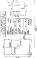
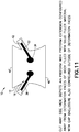
- Figure 1 is a schematic of an embodiment of the FEM modeling completed to design an AM preform having a body dimension and internal passage dimension configured to undergo deformation (i.e. with a filler material retained within the internal passage) and provide a product form having a final body dimension and internal passage dimension.
- Initial geometry of the AM component in accordance with the instant disclosure. Depicted in Figure 1 is the cut-away side view of an engineering drawing of the AM preform designed in the corresponding Example section, a table depicting some of the parameters of the AM preform (e.g.
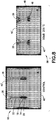
- Figure 2 depicts a cut away side view of a portion of the computer model results of the initial geometry of the AM preform (left) and final geometry of the product (right) expected utilizing the computer modeling approach, in accordance with one or more embodiments of the instant disclosure.
- the initial geometry and final expected geometry are depicted after deformation, under isothermal conditions, and frictionless axisymmetric compression.
- Figure 2 (initial vs. final) contrasts the different external shape profile (loss of concavity of sidewall from preform to product) as well as the change in shape of the internal cavity (preform depicts an elliptical portion vs. product depicts a circular portion).
- a 2" diameter and 2" high cylindrical sample was chosen as a prototype sample for experimental validation, based on factors including internal passage size and tonnage limit on the deformation simulator.
- Each AM preform was configured with a concentric internal void, where the void was configured with two corresponding channels configured to communicate from the void to the surface of the body of the AM preform.
- the two vertical passages (channels) in the AM preforms were utilized to enable filling the cavity via one channel while and the other to bleeding the air during filling and ensure a proper and complete fill.
- a deformation simulator was utilized on the three AM preforms.
- the deformation simulator was a compression machine (press) with a capacity of 150,000 lbs, configured with a furnace to heat the press surfaces and/or AM preform to deform via hot compression.
- the deformation simulator of this experimental section was utilized as a proxy for a single step forging die, where the simulator allowed for control over temperature, strain rate and strain of the AM preform to make a product having wrought properties.
- the furnace was heated up to the indicated temperature and deformation was completed (e.g. with heated surfaces of the press).
- deformation was completed (e.g. with heated surfaces of the press).
- PTFE polymer sheets configured between the AM preform deformation surfaces (upper and lower surfaces of the AM preform) and the press surfaces to promote frictionless surfaces of deformation.
- the estimated internal hydrostatic pressure was 5.5 KSI, and it is noted that the hydrostatic pressure during uniaxial deformation is about 1/3 of the applied flow stress.
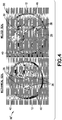
- molten tin is depicted on top of the product, which indicates that leakage occurred.
- the leakage of molten tin during deformation is believed to be the cause of the resulting collapse of the cavity and/or cracking of the cavity (i.e. leaking resulted in uncontrolled distortion of the internal passages during deformation).
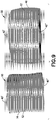
- the third sample was deformed in the deformation simulator at a temperature of 200°C, such that the filler material (tin) was maintained in a solid state during deformation in order to prevent escape from the cavity/void (leaking).
- This experiment was completed under constant load, as the maximum tonnage on the simulator was exceeded in maintaining the desired strain rate of 0.005/sec. As shown in Figure 6 , there was no evidence of any molten tin leakage on the top surface of the product.
- the filler material is enclosed in the internal passage of an AM preform during the AM build process. More specifically, a filler material is added to an AM preform, (if needed) allowed to solidify, and then additive manufacturing is resumed, such that additional build layers are configured over the opening to form an AM enclosure that retains the filler material within the AM preform.
- a cover e.g. substrate configured to extend across the opening of the internal passage
- successive additive manufacturing build layers to enclose the filler material into the internal passage
- the opening is capped (e.g. with a small plug), the surface is milled (i.e. to create a continuous build surface) and then returned to the additive machine to deposit at least one additional build layer onto the cap (and/or over the surface of the body that is configured with the opening of the internal passage).
- additional build layers are configured to provide an enclosure with a predetermined thickness (i.e. sufficient to retain the filler material in the internal passage while undergoing the deformation step).
Landscapes
- Engineering & Computer Science (AREA)
- Chemical & Material Sciences (AREA)
- Mechanical Engineering (AREA)
- Materials Engineering (AREA)
- Manufacturing & Machinery (AREA)
- Physics & Mathematics (AREA)
- Metallurgy (AREA)
- Organic Chemistry (AREA)
- Thermal Sciences (AREA)
- Optics & Photonics (AREA)
- Plasma & Fusion (AREA)
- Crystallography & Structural Chemistry (AREA)
- Forging (AREA)
- Processing And Handling Of Plastics And Other Materials For Molding In General (AREA)
- Treatment Of Steel In Its Molten State (AREA)
Claims (14)
- Procédé comprenant:la fabrication additive d'un matériau de base pour créer une préforme de FA (10), la préforme de FA étant conçue avec un corps (12) ayant un passage interne (16) défini à l'intérieur, le passage interne comportant en outre un vide (18) et/ou un canal (22) ;l'insertion d'un matériau d'apport (34) dans le passage interne de la préforme de FA ;la fermeture de la préforme de FA avec un composant d'enceinte (26) de telle sorte que le matériau d'apport est retenu dans le passage interne de la préforme de FA, le composant d'enceinte étant choisi parmi un dispositif de fixation mécanique, un capuchon, un bouchon ou une combinaison de ceux-ci ; etla déformation de la préforme de FA en une quantité suffisante pour créer un produit (50) ayant un passage interne, le produit étant conçu avec des propriétés corroyées pour ce matériau par l'intermédiaire de l'étape de déformation.
- Procédé selon la revendication 1, l'étape de fermeture comprenant en outre l'étanchéité du matériau d'apport à l'intérieur de la préforme de FA par l'intermédiaire d'un composant d'enceinte.
- Procédé selon la revendication 1 ou la revendication 2, l'étape de fermeture comprenant en outre la pression d'un bouchon (28) dans une ouverture dans le corps pour retenir le matériau d'apport dans le passage interne.
- Procédé selon l'une quelconque des revendications précédentes, l'étape de déformation comprenant en outre un corroyage.
- Procédé selon la revendication 4, comprenant en outre le recuit du produit et/ou l'écrouissage du produit.
- Procédé selon l'une quelconque des revendications précédentes, l'étape de déformation comprenant en outre le forgeage et de préférence l'étape de déformation comprenant en outre un forgeage par matriçage unique.
- Procédé selon l'une quelconque des revendications précédentes, l'étape de déformation comprenant en outre le laminage et/ou le laminage circulaire et/ou l'extrusion.
- Procédé selon l'une quelconque des revendications précédentes, comprenant en outre :
l'élimination du matériau d'apport du passage interne du produit et de préférence l'étape d'élimination comprenant en outre :l'ouverture du produit scellé contenant un matériau d'apport ;la fonte du matériau d'apport ; etla vidange du matériau d'apport du produit. - Procédé selon l'une quelconque des revendications précédentes, comprenant en outre la finition de la surface du produit.
- Procédé selon la revendication 9, la finition étant choisie dans le groupe constitué de :
l'usinage, le polissage, la finition de surface et/ou leurs combinaisons, ou l'étape de déformation comprenant en outre :
avant la déformation, la préchauffe de la préforme de FA pour faire fondre le matériau d'apport retenu dans le passage interne. - Procédé selon l'une quelconque des revendications précédentes, l'étape d'insertion comprenant en outre :l'attente pendant une durée suffisante pour que le matériau d'apport se solidifie dans le passage interne ; etla déformation de la préforme de FA contenant un matériau d'apport solidifié.
- Procédé selon l'une quelconque des revendications précédentes, le matériau d'apport comprenant au moins l'un parmi une huile, un polymère, un solvant organique et/ou inorganique, un métal et/ou un alliage métallique.
- Procédé selon la revendication 1, comprenant en outre, avant l'étape de fabrication additive, les étapes suivantes :le choix d'un produit cible ayant des propriétés corroyées cibles ; etla conception d'une préforme de FA cible avec une dimension de corps de préforme cible (14) et une dimension de vide de préforme cible (20), la préforme de FA cible étant conçue pour fournir le produit cible ayant une dimension de corps de produit cible (46) et une dimension de vide de produit cible (48) lors de la déformation, le corps de la préforme de FA produite à l'étape de fabrication additive ayant une dimension de corps de préforme correspondant à la dimension de corps de préforme cible, et le vide de la préforme de FA produite dans l'étape de fabrication additive ayant une dimension de vide de préforme correspondant à la dimension de vide de préforme cible, la préforme de FA étant déformée en une quantité suffisante pour former le produit cible ayant les propriétés corroyées cible ; etpar l'intermédiaire de l'étape de conception, le produit ayant un corps de produit ayant une dimension de corps de produit correspondant à la dimension de corps de produit cible, et un vide de produit ayant une dimension de vide de produit correspondant à la dimension de vide de produit cible.
- Procédé selon la revendication 13, l'étape de conception comprenant en outre la conception de la préforme de FA cible pour obtenir des propriétés corroyées de la préforme cible, et l'étape de déformation comprenant : le forgeage, et/ou le traitement thermomécanique, et/ou le'écrouissage.
Applications Claiming Priority (2)
| Application Number | Priority Date | Filing Date | Title |
|---|---|---|---|
| US201562132613P | 2015-03-13 | 2015-03-13 | |
| PCT/US2016/022331 WO2016149196A2 (fr) | 2015-03-13 | 2016-03-14 | Procédés de fabrication de produits corroyés avec des passages internes |
Publications (2)
| Publication Number | Publication Date |
|---|---|
| EP3268146A2 EP3268146A2 (fr) | 2018-01-17 |
| EP3268146B1 true EP3268146B1 (fr) | 2020-09-09 |
Family
ID=55640902
Family Applications (1)
| Application Number | Title | Priority Date | Filing Date |
|---|---|---|---|
| EP16712615.0A Not-in-force EP3268146B1 (fr) | 2015-03-13 | 2016-03-14 | Procédés de fabrication de produits forgés avec des passages internes |
Country Status (5)
| Country | Link |
|---|---|
| US (1) | US10385432B2 (fr) |
| EP (1) | EP3268146B1 (fr) |
| CN (1) | CN107848013B (fr) |
| CA (1) | CA2979561C (fr) |
| WO (1) | WO2016149196A2 (fr) |
Families Citing this family (20)
| Publication number | Priority date | Publication date | Assignee | Title |
|---|---|---|---|---|
| JP6646292B2 (ja) * | 2015-05-18 | 2020-02-14 | 国立研究開発法人産業技術総合研究所 | 金属積層造形と塑性加工を複合した金属素材の製造方法 |
| WO2017123995A1 (fr) * | 2016-01-14 | 2017-07-20 | Arconic Inc. | Procédés de fabrication de produits forgés et autres produits façonnés |
| US11135650B2 (en) * | 2016-05-24 | 2021-10-05 | Edison Welding Institute, Inc. | Laser-stirred powder bed fusion |
| GB201616942D0 (en) * | 2016-10-05 | 2016-11-16 | Imperial Innovations Limited | Method of creating a component using additive manufacturing |
| US10589370B2 (en) | 2017-05-08 | 2020-03-17 | General Electric Company | Automatic blocked hole identification |
| US10513076B1 (en) * | 2017-06-06 | 2019-12-24 | Anthony Freakes | 3D printing devices and methods |
| CN107470533B (zh) * | 2017-08-24 | 2023-10-27 | 山东中兴汽车零部件有限公司 | 一种惰轮加工方法及加工组合模具 |
| WO2019089736A1 (fr) | 2017-10-31 | 2019-05-09 | Arconic Inc. | Alliages d'aluminium améliorés et leurs procédés de production |
| EP3501694A1 (fr) | 2017-12-21 | 2019-06-26 | HIPtec AS | Procédé de fabrication d'un composant à base de métal possédant une cavité et composant à base de métal possédant une cavité |
| WO2019165136A1 (fr) * | 2018-02-21 | 2019-08-29 | Arconic Inc. | Produits d'alliage d'aluminum et leurs procédés de fabrication |
| DE102019204376A1 (de) * | 2018-04-12 | 2019-10-17 | Sms Group Gmbh | Schmierring für einen mechanischen Expander zum Kalibrieren von Großrohren |
| CN109128162B (zh) * | 2018-07-24 | 2020-01-03 | 华中科技大学 | 一种嵌入预制件的金属工件加工方法 |
| US11426818B2 (en) | 2018-08-10 | 2022-08-30 | The Research Foundation for the State University | Additive manufacturing processes and additively manufactured products |
| FR3097321B1 (fr) * | 2019-06-12 | 2021-06-25 | Safran | Éprouvette et procédé de mesure des contraintes résiduelles engendrées dans une pièce lors d’un procédé de fabrication additive de la pièce par fusion laser sur lits de poudre |
| EP3822005A1 (fr) | 2019-11-14 | 2021-05-19 | Rolls-Royce Corporation | Fabrication de filaments fusionnés d'alliages de brasage |
| US11820070B2 (en) | 2019-11-14 | 2023-11-21 | Rolls-Royce Corporation | Fused filament fabrication of high entropy alloys |
| CN111069320B (zh) * | 2019-11-14 | 2022-04-05 | 北京航星机器制造有限公司 | 一种局部增材制造预成形铝合金挤压成形工艺方法 |
| JP7382881B2 (ja) * | 2020-03-31 | 2023-11-17 | 三菱重工業株式会社 | 造形物の製造方法 |
| US11786973B2 (en) * | 2020-12-18 | 2023-10-17 | General Electric Company | Method for manufacturing a component using an additive process |
| US12311597B2 (en) | 2022-03-18 | 2025-05-27 | Wayne State University | Additive manufacturing system and unified additive-deformation-machining (ADM) process of manufacturing |
Family Cites Families (9)
| Publication number | Priority date | Publication date | Assignee | Title |
|---|---|---|---|---|
| CN1861296A (zh) | 2006-06-14 | 2006-11-15 | 华中科技大学 | 一种近净成形零件的方法 |
| FR2958193B1 (fr) | 2010-04-06 | 2012-06-29 | Saint Jean Ind | Procede de fabrication de pieces forgees en alliage leger incorporant des sections pleines ou tirees d'epaisseur |
| EP2551040A1 (fr) | 2011-07-25 | 2013-01-30 | EADS Deutschland GmbH | Procédé de fabrication de composant par pression isostatique à chaud |
| US20130039799A1 (en) | 2011-08-10 | 2013-02-14 | Summit Materials, Llc | Method of Making Near-Net Shapes From Powdered Metals |
| CN103302292B (zh) * | 2012-03-12 | 2015-08-12 | 中国科学院沈阳自动化研究所 | 一种激光直接成形钛合金零件工艺方法 |
| CN102837164A (zh) * | 2012-09-22 | 2012-12-26 | 山东泰金精密成型制品有限公司 | 汽车发动机曲轴轧锻结合成型方法及专用镦压模 |
| CN103143707A (zh) * | 2013-03-23 | 2013-06-12 | 钱波 | 新型金属粉末熔化快速成型机 |
| CN108500184A (zh) * | 2013-07-10 | 2018-09-07 | 奥科宁克有限公司 | 用于制作锻造产品和其他加工产品的方法 |
| US20150037498A1 (en) * | 2013-08-01 | 2015-02-05 | Siemens Energy, Inc. | Methods and preforms to mask holes and support open-substrate cavities during laser cladding |
-
2016
- 2016-03-14 CA CA2979561A patent/CA2979561C/fr not_active Expired - Fee Related
- 2016-03-14 CN CN201680027743.5A patent/CN107848013B/zh not_active Expired - Fee Related
- 2016-03-14 EP EP16712615.0A patent/EP3268146B1/fr not_active Not-in-force
- 2016-03-14 WO PCT/US2016/022331 patent/WO2016149196A2/fr not_active Ceased
- 2016-03-14 US US15/069,505 patent/US10385432B2/en not_active Expired - Fee Related
Non-Patent Citations (1)
| Title |
|---|
| None * |
Also Published As
| Publication number | Publication date |
|---|---|
| WO2016149196A2 (fr) | 2016-09-22 |
| CN107848013A (zh) | 2018-03-27 |
| CA2979561C (fr) | 2020-06-09 |
| CN107848013B (zh) | 2020-01-21 |
| US10385432B2 (en) | 2019-08-20 |
| WO2016149196A3 (fr) | 2016-11-03 |
| US20160298218A1 (en) | 2016-10-13 |
| CA2979561A1 (fr) | 2016-09-22 |
| EP3268146A2 (fr) | 2018-01-17 |
Similar Documents
| Publication | Publication Date | Title |
|---|---|---|
| EP3268146B1 (fr) | Procédés de fabrication de produits forgés avec des passages internes | |
| JP6214751B2 (ja) | 合金を鍛造するための物品、システム、および方法 | |
| RU2572639C2 (ru) | Способы смазки для улучшения способности деформироваться при штамповке | |
| EP3072611A2 (fr) | Composants en poudre métallique à dimension proche de la spécification finale et leurs procédés de production | |
| US9566671B2 (en) | Method for manufacturing a forging | |
| Bai et al. | A study of direct forging process for powder superalloys | |
| JP2016512172A5 (fr) | ||
| GB2538652A (en) | Additive manufacturing | |
| US9468970B2 (en) | Method for manufacturing a gear | |
| US9920403B2 (en) | Magnesium alloy member and production method therefor | |
| JP2008073763A (ja) | 車両ホイールの製造方法 | |
| Agu | The effects of 3D printed material properties on shaped charge liner performance | |
| Banerjee et al. | Experimental and numerical analysis of extrusion process for AA 7178 alloy with varying process parameters | |
| JP2000271695A (ja) | 成形品の製造方法 | |
| Boileau et al. | Superplastic response of continuously cast AZ31B magnesium sheet alloys | |
| US11584115B2 (en) | Method of manufacturing hybrid parts consisting of metallic and non-metallic materials at high temperature | |
| Smythe | Development of the ConformTM process for the recycling of waste titanium into wire | |
| Förster et al. | Enhancing the applicability of Al-Mg compounds by using forming and welding technologies | |
| Andreae et al. | Evaluating the Characteristics of Cast AZ91 Magnesium Alloy for Upset Protrusion Joining Method | |
| MAY | Additively Manufactured Materials Allowables for Critical Applications | |
| Petersen | Investigation of the hot deformation of sintered titanium compacts produced from direct reduction powder | |
| GB2536483B (en) | A method of Forming a Metal Component | |
| Hu et al. | Effects of extrusion-shear and direct extrusion on the plastic deformation of AZ31 magnesium alloy | |
| Kuhn et al. | Designing for Aluminum Forging | |
| Moussa | Transient processing and characterization of advanced materials |
Legal Events
| Date | Code | Title | Description |
|---|---|---|---|
| STAA | Information on the status of an ep patent application or granted ep patent |
Free format text: STATUS: THE INTERNATIONAL PUBLICATION HAS BEEN MADE |
|
| PUAI | Public reference made under article 153(3) epc to a published international application that has entered the european phase |
Free format text: ORIGINAL CODE: 0009012 |
|
| STAA | Information on the status of an ep patent application or granted ep patent |
Free format text: STATUS: REQUEST FOR EXAMINATION WAS MADE |
|
| 17P | Request for examination filed |
Effective date: 20171012 |
|
| AK | Designated contracting states |
Kind code of ref document: A2 Designated state(s): AL AT BE BG CH CY CZ DE DK EE ES FI FR GB GR HR HU IE IS IT LI LT LU LV MC MK MT NL NO PL PT RO RS SE SI SK SM TR |
|
| AX | Request for extension of the european patent |
Extension state: BA ME |
|
| DAV | Request for validation of the european patent (deleted) | ||
| DAX | Request for extension of the european patent (deleted) | ||
| STAA | Information on the status of an ep patent application or granted ep patent |
Free format text: STATUS: EXAMINATION IS IN PROGRESS |
|
| 17Q | First examination report despatched |
Effective date: 20190701 |
|
| RAP1 | Party data changed (applicant data changed or rights of an application transferred) |
Owner name: ARCONIC INC. |
|
| GRAP | Despatch of communication of intention to grant a patent |
Free format text: ORIGINAL CODE: EPIDOSNIGR1 |
|
| STAA | Information on the status of an ep patent application or granted ep patent |
Free format text: STATUS: GRANT OF PATENT IS INTENDED |
|
| INTG | Intention to grant announced |
Effective date: 20200326 |
|
| GRAS | Grant fee paid |
Free format text: ORIGINAL CODE: EPIDOSNIGR3 |
|
| RAP1 | Party data changed (applicant data changed or rights of an application transferred) |
Owner name: HOWMET AEROSPACE INC. |
|
| GRAA | (expected) grant |
Free format text: ORIGINAL CODE: 0009210 |
|
| STAA | Information on the status of an ep patent application or granted ep patent |
Free format text: STATUS: THE PATENT HAS BEEN GRANTED |
|
| AK | Designated contracting states |
Kind code of ref document: B1 Designated state(s): AL AT BE BG CH CY CZ DE DK EE ES FI FR GB GR HR HU IE IS IT LI LT LU LV MC MK MT NL NO PL PT RO RS SE SI SK SM TR |
|
| REG | Reference to a national code |
Ref country code: GB Ref legal event code: FG4D |
|
| REG | Reference to a national code |
Ref country code: AT Ref legal event code: REF Ref document number: 1310929 Country of ref document: AT Kind code of ref document: T Effective date: 20200915 Ref country code: CH Ref legal event code: EP |
|
| REG | Reference to a national code |
Ref country code: DE Ref legal event code: R096 Ref document number: 602016043649 Country of ref document: DE |
|
| REG | Reference to a national code |
Ref country code: IE Ref legal event code: FG4D |
|
| REG | Reference to a national code |
Ref country code: LT Ref legal event code: MG4D |
|
| PG25 | Lapsed in a contracting state [announced via postgrant information from national office to epo] |
Ref country code: SE Free format text: LAPSE BECAUSE OF FAILURE TO SUBMIT A TRANSLATION OF THE DESCRIPTION OR TO PAY THE FEE WITHIN THE PRESCRIBED TIME-LIMIT Effective date: 20200909 Ref country code: LT Free format text: LAPSE BECAUSE OF FAILURE TO SUBMIT A TRANSLATION OF THE DESCRIPTION OR TO PAY THE FEE WITHIN THE PRESCRIBED TIME-LIMIT Effective date: 20200909 Ref country code: HR Free format text: LAPSE BECAUSE OF FAILURE TO SUBMIT A TRANSLATION OF THE DESCRIPTION OR TO PAY THE FEE WITHIN THE PRESCRIBED TIME-LIMIT Effective date: 20200909 Ref country code: FI Free format text: LAPSE BECAUSE OF FAILURE TO SUBMIT A TRANSLATION OF THE DESCRIPTION OR TO PAY THE FEE WITHIN THE PRESCRIBED TIME-LIMIT Effective date: 20200909 Ref country code: GR Free format text: LAPSE BECAUSE OF FAILURE TO SUBMIT A TRANSLATION OF THE DESCRIPTION OR TO PAY THE FEE WITHIN THE PRESCRIBED TIME-LIMIT Effective date: 20201210 Ref country code: BG Free format text: LAPSE BECAUSE OF FAILURE TO SUBMIT A TRANSLATION OF THE DESCRIPTION OR TO PAY THE FEE WITHIN THE PRESCRIBED TIME-LIMIT Effective date: 20201209 Ref country code: NO Free format text: LAPSE BECAUSE OF FAILURE TO SUBMIT A TRANSLATION OF THE DESCRIPTION OR TO PAY THE FEE WITHIN THE PRESCRIBED TIME-LIMIT Effective date: 20201209 |
|
| REG | Reference to a national code |
Ref country code: AT Ref legal event code: MK05 Ref document number: 1310929 Country of ref document: AT Kind code of ref document: T Effective date: 20200909 |
|
| REG | Reference to a national code |
Ref country code: NL Ref legal event code: MP Effective date: 20200909 |
|
| PG25 | Lapsed in a contracting state [announced via postgrant information from national office to epo] |
Ref country code: RS Free format text: LAPSE BECAUSE OF FAILURE TO SUBMIT A TRANSLATION OF THE DESCRIPTION OR TO PAY THE FEE WITHIN THE PRESCRIBED TIME-LIMIT Effective date: 20200909 Ref country code: PL Free format text: LAPSE BECAUSE OF FAILURE TO SUBMIT A TRANSLATION OF THE DESCRIPTION OR TO PAY THE FEE WITHIN THE PRESCRIBED TIME-LIMIT Effective date: 20200909 Ref country code: LV Free format text: LAPSE BECAUSE OF FAILURE TO SUBMIT A TRANSLATION OF THE DESCRIPTION OR TO PAY THE FEE WITHIN THE PRESCRIBED TIME-LIMIT Effective date: 20200909 |
|
| PG25 | Lapsed in a contracting state [announced via postgrant information from national office to epo] |
Ref country code: SM Free format text: LAPSE BECAUSE OF FAILURE TO SUBMIT A TRANSLATION OF THE DESCRIPTION OR TO PAY THE FEE WITHIN THE PRESCRIBED TIME-LIMIT Effective date: 20200909 Ref country code: RO Free format text: LAPSE BECAUSE OF FAILURE TO SUBMIT A TRANSLATION OF THE DESCRIPTION OR TO PAY THE FEE WITHIN THE PRESCRIBED TIME-LIMIT Effective date: 20200909 Ref country code: PT Free format text: LAPSE BECAUSE OF FAILURE TO SUBMIT A TRANSLATION OF THE DESCRIPTION OR TO PAY THE FEE WITHIN THE PRESCRIBED TIME-LIMIT Effective date: 20210111 Ref country code: CZ Free format text: LAPSE BECAUSE OF FAILURE TO SUBMIT A TRANSLATION OF THE DESCRIPTION OR TO PAY THE FEE WITHIN THE PRESCRIBED TIME-LIMIT Effective date: 20200909 Ref country code: EE Free format text: LAPSE BECAUSE OF FAILURE TO SUBMIT A TRANSLATION OF THE DESCRIPTION OR TO PAY THE FEE WITHIN THE PRESCRIBED TIME-LIMIT Effective date: 20200909 |
|
| PGFP | Annual fee paid to national office [announced via postgrant information from national office to epo] |
Ref country code: FR Payment date: 20210219 Year of fee payment: 6 |
|
| PG25 | Lapsed in a contracting state [announced via postgrant information from national office to epo] |
Ref country code: IS Free format text: LAPSE BECAUSE OF FAILURE TO SUBMIT A TRANSLATION OF THE DESCRIPTION OR TO PAY THE FEE WITHIN THE PRESCRIBED TIME-LIMIT Effective date: 20210109 Ref country code: ES Free format text: LAPSE BECAUSE OF FAILURE TO SUBMIT A TRANSLATION OF THE DESCRIPTION OR TO PAY THE FEE WITHIN THE PRESCRIBED TIME-LIMIT Effective date: 20200909 Ref country code: AL Free format text: LAPSE BECAUSE OF FAILURE TO SUBMIT A TRANSLATION OF THE DESCRIPTION OR TO PAY THE FEE WITHIN THE PRESCRIBED TIME-LIMIT Effective date: 20200909 Ref country code: AT Free format text: LAPSE BECAUSE OF FAILURE TO SUBMIT A TRANSLATION OF THE DESCRIPTION OR TO PAY THE FEE WITHIN THE PRESCRIBED TIME-LIMIT Effective date: 20200909 |
|
| PGFP | Annual fee paid to national office [announced via postgrant information from national office to epo] |
Ref country code: DE Payment date: 20210217 Year of fee payment: 6 Ref country code: GB Payment date: 20210219 Year of fee payment: 6 |
|
| REG | Reference to a national code |
Ref country code: DE Ref legal event code: R097 Ref document number: 602016043649 Country of ref document: DE |
|
| PG25 | Lapsed in a contracting state [announced via postgrant information from national office to epo] |
Ref country code: SK Free format text: LAPSE BECAUSE OF FAILURE TO SUBMIT A TRANSLATION OF THE DESCRIPTION OR TO PAY THE FEE WITHIN THE PRESCRIBED TIME-LIMIT Effective date: 20200909 |
|
| PLBE | No opposition filed within time limit |
Free format text: ORIGINAL CODE: 0009261 |
|
| STAA | Information on the status of an ep patent application or granted ep patent |
Free format text: STATUS: NO OPPOSITION FILED WITHIN TIME LIMIT |
|
| 26N | No opposition filed |
Effective date: 20210610 |
|
| PG25 | Lapsed in a contracting state [announced via postgrant information from national office to epo] |
Ref country code: DK Free format text: LAPSE BECAUSE OF FAILURE TO SUBMIT A TRANSLATION OF THE DESCRIPTION OR TO PAY THE FEE WITHIN THE PRESCRIBED TIME-LIMIT Effective date: 20200909 Ref country code: SI Free format text: LAPSE BECAUSE OF FAILURE TO SUBMIT A TRANSLATION OF THE DESCRIPTION OR TO PAY THE FEE WITHIN THE PRESCRIBED TIME-LIMIT Effective date: 20200909 |
|
| PG25 | Lapsed in a contracting state [announced via postgrant information from national office to epo] |
Ref country code: MC Free format text: LAPSE BECAUSE OF FAILURE TO SUBMIT A TRANSLATION OF THE DESCRIPTION OR TO PAY THE FEE WITHIN THE PRESCRIBED TIME-LIMIT Effective date: 20200909 Ref country code: IT Free format text: LAPSE BECAUSE OF FAILURE TO SUBMIT A TRANSLATION OF THE DESCRIPTION OR TO PAY THE FEE WITHIN THE PRESCRIBED TIME-LIMIT Effective date: 20200909 |
|
| REG | Reference to a national code |
Ref country code: CH Ref legal event code: PL |
|
| REG | Reference to a national code |
Ref country code: BE Ref legal event code: MM Effective date: 20210331 |
|
| PG25 | Lapsed in a contracting state [announced via postgrant information from national office to epo] |
Ref country code: CH Free format text: LAPSE BECAUSE OF NON-PAYMENT OF DUE FEES Effective date: 20210331 Ref country code: LI Free format text: LAPSE BECAUSE OF NON-PAYMENT OF DUE FEES Effective date: 20210331 Ref country code: LU Free format text: LAPSE BECAUSE OF NON-PAYMENT OF DUE FEES Effective date: 20210314 Ref country code: IE Free format text: LAPSE BECAUSE OF NON-PAYMENT OF DUE FEES Effective date: 20210314 |
|
| PG25 | Lapsed in a contracting state [announced via postgrant information from national office to epo] |
Ref country code: BE Free format text: LAPSE BECAUSE OF NON-PAYMENT OF DUE FEES Effective date: 20210331 |
|
| REG | Reference to a national code |
Ref country code: DE Ref legal event code: R119 Ref document number: 602016043649 Country of ref document: DE |
|
| GBPC | Gb: european patent ceased through non-payment of renewal fee |
Effective date: 20220314 |
|
| PG25 | Lapsed in a contracting state [announced via postgrant information from national office to epo] |
Ref country code: GB Free format text: LAPSE BECAUSE OF NON-PAYMENT OF DUE FEES Effective date: 20220314 Ref country code: FR Free format text: LAPSE BECAUSE OF NON-PAYMENT OF DUE FEES Effective date: 20220331 Ref country code: DE Free format text: LAPSE BECAUSE OF NON-PAYMENT OF DUE FEES Effective date: 20221001 |
|
| PG25 | Lapsed in a contracting state [announced via postgrant information from national office to epo] |
Ref country code: NL Free format text: LAPSE BECAUSE OF NON-PAYMENT OF DUE FEES Effective date: 20200923 Ref country code: CY Free format text: LAPSE BECAUSE OF FAILURE TO SUBMIT A TRANSLATION OF THE DESCRIPTION OR TO PAY THE FEE WITHIN THE PRESCRIBED TIME-LIMIT Effective date: 20200909 |
|
| PG25 | Lapsed in a contracting state [announced via postgrant information from national office to epo] |
Ref country code: HU Free format text: LAPSE BECAUSE OF FAILURE TO SUBMIT A TRANSLATION OF THE DESCRIPTION OR TO PAY THE FEE WITHIN THE PRESCRIBED TIME-LIMIT; INVALID AB INITIO Effective date: 20160314 |
|
| PG25 | Lapsed in a contracting state [announced via postgrant information from national office to epo] |
Ref country code: MK Free format text: LAPSE BECAUSE OF FAILURE TO SUBMIT A TRANSLATION OF THE DESCRIPTION OR TO PAY THE FEE WITHIN THE PRESCRIBED TIME-LIMIT Effective date: 20200909 |
|
| PG25 | Lapsed in a contracting state [announced via postgrant information from national office to epo] |
Ref country code: MT Free format text: LAPSE BECAUSE OF FAILURE TO SUBMIT A TRANSLATION OF THE DESCRIPTION OR TO PAY THE FEE WITHIN THE PRESCRIBED TIME-LIMIT Effective date: 20200909 |
|
| PG25 | Lapsed in a contracting state [announced via postgrant information from national office to epo] |
Ref country code: TR Free format text: LAPSE BECAUSE OF FAILURE TO SUBMIT A TRANSLATION OF THE DESCRIPTION OR TO PAY THE FEE WITHIN THE PRESCRIBED TIME-LIMIT Effective date: 20200909 |