EP3268678B1 - Trageinrichtung für solarmodule, photovoltaikaufstellung mit mehreren trageinrichtungen und verfahren zum aufstellen einer solchen trageinrichtung - Google Patents
Trageinrichtung für solarmodule, photovoltaikaufstellung mit mehreren trageinrichtungen und verfahren zum aufstellen einer solchen trageinrichtung Download PDFInfo
- Publication number
- EP3268678B1 EP3268678B1 EP16707730.4A EP16707730A EP3268678B1 EP 3268678 B1 EP3268678 B1 EP 3268678B1 EP 16707730 A EP16707730 A EP 16707730A EP 3268678 B1 EP3268678 B1 EP 3268678B1
- Authority
- EP
- European Patent Office
- Prior art keywords
- support stand
- bridge
- support
- bearing
- support device
- Prior art date
- Legal status (The legal status is an assumption and is not a legal conclusion. Google has not performed a legal analysis and makes no representation as to the accuracy of the status listed.)
- Active
Links
Images



Classifications
-
- H—ELECTRICITY
- H02—GENERATION; CONVERSION OR DISTRIBUTION OF ELECTRIC POWER
- H02S—GENERATION OF ELECTRIC POWER BY CONVERSION OF INFRARED RADIATION, VISIBLE LIGHT OR ULTRAVIOLET LIGHT, e.g. USING PHOTOVOLTAIC [PV] MODULES
- H02S20/00—Supporting structures for PV modules
- H02S20/10—Supporting structures directly fixed to the ground
-
- F—MECHANICAL ENGINEERING; LIGHTING; HEATING; WEAPONS; BLASTING
- F24—HEATING; RANGES; VENTILATING
- F24S—SOLAR HEAT COLLECTORS; SOLAR HEAT SYSTEMS
- F24S30/00—Arrangements for moving or orienting solar heat collector modules
- F24S30/40—Arrangements for moving or orienting solar heat collector modules for rotary movement
- F24S30/42—Arrangements for moving or orienting solar heat collector modules for rotary movement with only one rotation axis
- F24S30/425—Horizontal axis
-
- F—MECHANICAL ENGINEERING; LIGHTING; HEATING; WEAPONS; BLASTING
- F24—HEATING; RANGES; VENTILATING
- F24S—SOLAR HEAT COLLECTORS; SOLAR HEAT SYSTEMS
- F24S25/00—Arrangement of stationary mountings or supports for solar heat collector modules
- F24S25/10—Arrangement of stationary mountings or supports for solar heat collector modules extending in directions away from a supporting surface
-
- F—MECHANICAL ENGINEERING; LIGHTING; HEATING; WEAPONS; BLASTING
- F24—HEATING; RANGES; VENTILATING
- F24S—SOLAR HEAT COLLECTORS; SOLAR HEAT SYSTEMS
- F24S25/00—Arrangement of stationary mountings or supports for solar heat collector modules
- F24S25/60—Fixation means, e.g. fasteners, specially adapted for supporting solar heat collector modules
- F24S25/61—Fixation means, e.g. fasteners, specially adapted for supporting solar heat collector modules for fixing to the ground or to building structures
- F24S25/617—Elements driven into the ground, e.g. anchor-piles; Foundations for supporting elements; Connectors for connecting supporting structures to the ground or to flat horizontal surfaces
-
- H—ELECTRICITY
- H02—GENERATION; CONVERSION OR DISTRIBUTION OF ELECTRIC POWER
- H02S—GENERATION OF ELECTRIC POWER BY CONVERSION OF INFRARED RADIATION, VISIBLE LIGHT OR ULTRAVIOLET LIGHT, e.g. USING PHOTOVOLTAIC [PV] MODULES
- H02S20/00—Supporting structures for PV modules
- H02S20/30—Supporting structures being movable or adjustable, e.g. for angle adjustment
- H02S20/32—Supporting structures being movable or adjustable, e.g. for angle adjustment specially adapted for solar tracking
-
- F—MECHANICAL ENGINEERING; LIGHTING; HEATING; WEAPONS; BLASTING
- F24—HEATING; RANGES; VENTILATING
- F24S—SOLAR HEAT COLLECTORS; SOLAR HEAT SYSTEMS
- F24S30/00—Arrangements for moving or orienting solar heat collector modules
- F24S2030/10—Special components
- F24S2030/15—Bearings
-
- Y—GENERAL TAGGING OF NEW TECHNOLOGICAL DEVELOPMENTS; GENERAL TAGGING OF CROSS-SECTIONAL TECHNOLOGIES SPANNING OVER SEVERAL SECTIONS OF THE IPC; TECHNICAL SUBJECTS COVERED BY FORMER USPC CROSS-REFERENCE ART COLLECTIONS [XRACs] AND DIGESTS
- Y02—TECHNOLOGIES OR APPLICATIONS FOR MITIGATION OR ADAPTATION AGAINST CLIMATE CHANGE
- Y02E—REDUCTION OF GREENHOUSE GAS [GHG] EMISSIONS, RELATED TO ENERGY GENERATION, TRANSMISSION OR DISTRIBUTION
- Y02E10/00—Energy generation through renewable energy sources
- Y02E10/40—Solar thermal energy, e.g. solar towers
- Y02E10/47—Mountings or tracking
-
- Y—GENERAL TAGGING OF NEW TECHNOLOGICAL DEVELOPMENTS; GENERAL TAGGING OF CROSS-SECTIONAL TECHNOLOGIES SPANNING OVER SEVERAL SECTIONS OF THE IPC; TECHNICAL SUBJECTS COVERED BY FORMER USPC CROSS-REFERENCE ART COLLECTIONS [XRACs] AND DIGESTS
- Y02—TECHNOLOGIES OR APPLICATIONS FOR MITIGATION OR ADAPTATION AGAINST CLIMATE CHANGE
- Y02E—REDUCTION OF GREENHOUSE GAS [GHG] EMISSIONS, RELATED TO ENERGY GENERATION, TRANSMISSION OR DISTRIBUTION
- Y02E10/00—Energy generation through renewable energy sources
- Y02E10/50—Photovoltaic [PV] energy
Definitions
- the present invention relates to a support device formed from several parts.
- Support devices for pivot axes of solar modules formed from several parts are already known from the prior art. So-called IPE carriers are provided in practice. If such supports are to be installed in a floor surface, boreholes are to be excavated for this purpose, which are then backfilled and compacted, after which the support is introduced into the ground under the action of force.
- an object of the invention can be seen in providing a support device, a photovoltaic installation and a method for setting up a support device provided for pivot axes of solar modules, which do not at least partially have the disadvantages mentioned above.
- ES 1 119 081 U discloses a support device for pivoting axes of solar modules formed from several parts according to the preamble of claim 1.
- the invention relates to a support device formed from several parts for pivot axes of solar modules.
- the support device has at least one first support foot and at least one second support foot, which are each designed for anchoring in a floor surface.
- the at least one first support foot and / or the at least one second support foot can have a circular cross section.
- the at least one first support foot and the at least one second support foot can be of identical design.
- the carrying device also comprises a bridge which mechanically couples the at least one first support foot to the at least one second support foot and a bearing which is designed to receive a pivot axis.
- the camp is supported by the bridge.
- the at least one first support foot and the at least one second support foot are detachably connected to the bridge. It is conceivable, for example, that the at least one first support foot and the at least one second support foot are received positively via the bridge.
- the bridge can thus each form a receptacle for the at least one first support leg and the at least one second support leg, into which respective receptacle the at least one first support leg and the at least one second support leg can be inserted in a form-fitting or essentially form-fitting manner.
- the at least one first support foot and / or the at least one second support foot each form a thread at their free end region pointing in the direction away from the bridge. Furthermore, the at least one first support foot and / or the at least one second support foot can taper in the direction of their respective free end region pointing away from the bridge, thereby introducing or anchoring the at least one first support foot and / or the at least one second support foot is simplified in a floor space.
- the thread is expediently designed to screw the at least one first support foot and / or the at least one second support foot into a floor surface.
- the carrying device comprises at least one clamping bracket which can be fastened to the bridge and via which the at least one first support foot and / or the at least one second support foot can be fixed to the bridge when subjected to a force.
- the at least one clamping bracket can be designed to positively receive the at least one first support foot and / or the at least one second support foot.
- at least one separate clamping bracket can be provided for the at least one first support foot and the at least one second support foot.
- the at least one first support foot and the at least one second support foot can then be fixed to the bridge under the action of their own respective clamping bracket.
- the at least one clamping bracket is pivotally mounted on the bridge and for the force-loaded fixing of the at least one first support foot and / or the at least a second support leg is fixed to the bridge in a certain pivot position.
- At least one fixing means preferably in the form of a screw connection, can be provided, by means of which the clamping bracket can be held in a specific clamping position in order to fix the at least one first support foot and / or the at least one second support foot to the bridge.
- Embodiments in which the bearing can be releasably attached to the bridge have also proven successful.
- snap, snap and / or clamp connections are conceivable, by means of which the bearing can be detachably fixed to the bridge.
- the bearing can be detachably attached to the bridge via at least one screw connection.
- the bridge mechanically couples the at least one first support foot relative to the at least one second support foot.
- the longitudinal axes of the at least one first support foot and the at least one second support foot can thus be oriented inclined to one another.
- embodiments have proven useful in which the at least one first support foot and the at least one second support foot form an angle when the coupling is inclined, which is set between 0 ° and 90 ° and preferably between 10 ° and 35 °. Furthermore, the angle cannot be more than 25 ° and not less than 15 °.
- the bridge can be formed as a molded shell comprising at least two housing parts, which provide at least two housing parts with a corresponding receptacle for the positive connection of the at least one first support foot and / or the at least one second support foot to the bridge.
- the at least one first support foot and / or the at least one second support foot can be designed as a hollow tube.
- the at least one first support foot and / or the at least one second support foot can, as already mentioned above, have a circular cross section.
- the invention also relates to a photovoltaic installation.
- the photovoltaic array includes a large number of solar modules and at least one Swivel axis to which the solar modules are fixed and a plurality of support devices according to one embodiment or more embodiments of the above description.
- the at least one pivot axis is received via the bearings of the multiple support devices.
- the invention further relates to a method for setting up a support device provided for pivoting axes of solar modules.
- a support device provided for pivoting axes of solar modules.
- At least one first support foot is anchored in a floor area. Furthermore, at least one second support foot is anchored in a floor surface.
- the at least one first support foot anchored in the floor surface is mechanically coupled to the at least one second support foot anchored in the floor surface via a bridge which carries a bearing for receiving a pivot axis and / or to which a bearing for receiving a pivot axis is fastened becomes.
- the at least one first support foot and / or the at least one second support foot form a thread or screw thread in the region of a respective free end, via which thread the at least one first support foot and / or the at least one second support foot is screwed into the floor surface for anchoring become.
- At least one clamping bracket is fixed to the bridge, as a result of which the at least one first support foot and / or the at least one second support foot is held in a force-actuated manner via the at least one clamping bracket fixed to the bridge.
- Embodiments in which the bearing is releasably attached to the bridge for receiving a pivot axis have also proven successful.
- screw connections can be provided, by means of which the bearing is releasably attached to the bridge in order to accommodate a pivot axis.
- the bridge mechanically couples the at least one first support foot to one another with respect to the at least one second support foot.
- the bridge mechanically couples the at least one first support foot relative to the at least one second support foot at an angle between 0 ° and 90 ° and preferably between 10 ° and 35 °.
- the bridge mechanically couples the at least one first support foot relative to the at least one second support foot at an angle to one another that is not more than 25 ° and not less than 15 °.
- the bridge can comprise at least two housing parts, the housing parts being connected to one another for mechanical coupling and thereby receiving the at least one first support foot and / or the at least one second support foot in a form-fitting manner.
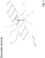
- FIG. 1 shows a horizontal tracker 100 which is already known from the prior art.
- a partial region of a pivot axis 1, which is held by a bearing 4, can be seen.
- the bearing 4 is fastened to a base foundation, here an IPE carrier 5.
- solar modules 2 can be seen, which are attached to the pivot axis 1 by means of module carriers 3.
- the embodiment shown relates to a common design for horizontal trackers 100, the illustrated mounting being repeated several times over the entire length of the pivot axis 1 (not shown here).
- IPE beams 5 or material-saving sheet metal profiles are rammed into a floor surface 6 as floor foundations.
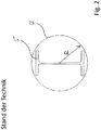
- Figure 2 shows a carrier 5 of the horizontal tracker 100 Figure 1 , Also shown is an enveloping circle 7 for the IPE carrier 5. If ground conditions do not allow the IPE carriers 5 to be rammed directly into a bottom surface 6, corresponding boreholes with an enveloping circle radius R must be drilled in methods known from the prior art. The boreholes are then backfilled and compressed. IPE carriers 5 are then rammed into the backfilled and compressed boreholes. For installation work, this means a lot of additional time and money.
- Figure 3 shows a schematic perspective view of a first embodiment of a support device 10 according to the invention and a first embodiment of a photovoltaic installation 20 according to the invention.
- the photovoltaic installation 20 comprises a multiplicity of solar modules 2, a swivel axis 1 and also a plurality of module carriers 3, by means of which the solar modules 2 are fastened to the swivel axis 1. Furthermore, the photovoltaic installation 20 has a plurality of support devices 10, of which in Figure 3 a support device 10 can be seen. The pivot axis 1 is rotatably received via the bearings 4 of the plurality of support devices 10.
- Support device 10 to be recognized comprises a first support leg SF1 and a second support leg SF2, each of which is anchored in a floor surface 6.
- the first support leg SF1 and the second support leg SF2 are oriented parallel to one another.
- a bridge BB can be seen, which mechanically couples the first support leg SF1 and the second support leg SF2 to one another and keeps them in their relative orientation to one another.
- the pivot axis 1 is received via the bearing 4.
- the bearing 4 is also carried by the bridge BB.
- Both the first support leg SF1 and the second support leg SF2 are detachably connected to the bridge BB or detachably attached to the bridge BB.
- the bearing 4 is also releasably held on the bridge BB or can be removed from the bridge BB.
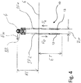
- FIG 4 shows the support device 10 of the embodiment Figure 3 clarifying other aspects.
- a main loading direction FH acts horizontally on the pivot bearing 4 at a height HS, which has the pivot axis 1 with respect to the bottom surface 6.
- the bridge BB mechanically coupling the first and the second support feet SF1 and SF2 converts these loads into compressive and tensile forces FD and FZ, which the first support foot SF1 and the second support foot SF2 introduce into the floor surface 6 at a distance ASF can.
- An embedment depth ET of the first support leg SF1 and the second support leg SF2 can be adapted to the soil conditions.
- first support leg SF1 and the second support leg SF2 each form a thread 13 at their free end region pointing in the direction away from the bridge BB.
- the first support leg SF1 and the second support leg SF2 are off in the embodiment Figure 4 oriented parallel to each other or are made in the embodiment Figure 4 mechanically coupled parallel to each other via the bridge BB.
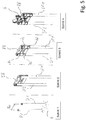
- Figure 5 shows individual steps as they can be provided in a conceivable embodiment of the method according to the invention.
- Step 1 A first support leg SF1 and a second support leg SF2 are introduced into a floor surface 6 at a certain relative distance from one another and anchored in a floor surface 6.
- the support feet SF1 and SF2 anchored in the base surface 6 or introduced into the base surface 6 are then oriented parallel to one another and protrude from the base surface 6 with approximately the same amount of their respective longitudinal extent.
- the support feet SF1 and SF2 each have a thread 13 (cf. Figure 4 ).
- the first support foot SF1 and the second support foot SF2 are screwed into the floor surface 6 for anchoring or for insertion into the floor surface 6.
- Steps 2 and 3 The first support foot SF1 anchored in the floor surface 6 and the second support foot SF2 anchored in the floor surface 6 are mechanically coupled to one another via a bridge BB.
- the bridge BB holds the first support foot 6 anchored in the bottom surface 6 in its relative position relative to the second support foot SF2 anchored in the bottom surface 6.
- Clamping brackets 8a to 8d are provided for the mechanical coupling, by means of which the first support foot SF1 and the second support foot SF2 are fixed to the bridge BB under load.
- Step 4 A bearing 4 is attached to the bridge BB. Step 4 takes place after steps 1 to 3.
- the bearing 4 can be fastened to the bridge BB, for example, by means of screw connections.
- Figure 6 shows a schematic top view of an embodiment of a carrying device 10 with clarification of further aspects.
- the first support leg SF1 and the second support leg SF2 are each designed as hollow tubes and have a circular cross section.
- Figure 6 shows that a circumferential surface of the first support foot SF1 and a circumferential surface of the second support foot SF2 lie along the circumference of the bridge BB by more than 90 ° or at least approximately 180 °.
- the first support leg SF1 and the second support leg SF2 are thus positively received via the bridge BB.
- the first support leg SF1 and the second support leg SF2 are held on the bridge BB by means of the clamping brackets 8a to 8d.
- Figure 7 shows a schematic view of a further embodiment of a carrying device 10 according to the invention.
- the first support leg SF1 and the second support leg SF2 are mechanically coupled to one another by the bridge BB in such a way that the first support leg SF1 and the second support leg SF2 together with the bridge BB have an A-shape form.
- the first support leg SF1 or a longitudinal axis of the first support leg SF1 and the second support leg SF2 or a longitudinal axis of the second support leg SF2 form an angle W which is not less than 15 ° and not greater than 25 °.
- the bridge BB comprises in the exemplary embodiment Figure 7 a two-part molded shell FS, which is formed from mutually corresponding molded shell halves and by means of which molded shell FS the first support leg SF1 and the second support leg SF2 can be received in a form-fitting manner.
- a rotary bearing 4 for a pivot axis 1, not shown, is arranged above the molded shell FS. Since high lateral forces occur in conceivable uses for the carrying device 10 according to the invention, the in FIG Figure 7 shown main load direction FH result. Using the A-shaped support feet SF1 and SF2, the side forces which are introduced to the molded shell FS connecting the support feet SF1 and SF2 can be converted into tensile and compressive forces FZ and FD, so that the entire support device 10 is very stable ,
- Figure 8 shows the embodiment of a support device 10 Figure 7 clarifying other aspects.
- the Figures 8a and 8b different possibilities for setting up or inserting an embodiment of a carrying device 10 according to the invention into a floor surface 6 Fig. 8a the first support leg SF1 and the second support leg SF2 have a large embedment depth ET ', which, for example, due to certain ground conditions Figure 8a may be necessary to set up a photovoltaic system 20 (cf. Figure 3 ) to store stably.
- the large embedment depth ET 'of the support feet SF1 and SF2 in the base surface 6 results in a lower height of the pivot axis HS' and a lower base A SF 'of the support feet SF1 and SF2 in the region of the base surface 6.
- a smaller embedment depth ET "in the base 6 is sufficient, the pivot axis 1 has a larger one Height HS ". This results in a comparison to Fig. 8a larger base A SF "of the support feet SF1 and SF2 in the area of the bottom surface 6.
- a technical effect of the carrying device 10 according to the embodiment Figures 8a and 8b thus consists in that when the distance of the pivot axis 1 from the floor HS 'to HS "increases, the width of the base A SF ' to A SF " also increases. With a variable integration depth of the support feet SF1 and SF2, hardly any changes in the statics are necessary.
- the static conditions of the carrying device 10 remain approximately the same, while in the case of uniform profiles, such as IPE profiles, the limits of the statics are quickly exceeded.
- Figure 9 shows individual steps as they can be provided in a conceivable embodiment of the method according to the invention.
- Figure 9 a method for setting up an embodiment of a support device 10 provided for pivot axes 1 of solar modules 2 according to FIG Figure 7 ,
- Step 1 ' a first support leg SF1 and a second support leg SF2 are screwed into a bottom surface 6 so that they form an angle W of approximately 20 ° with one another.
- the first support leg SF1 and the second support leg SF2 each form a thread 13 (cf. Figure 8 ).
- Step 2 ' the two mold shell halves FS' and FS "are attached to connect the screw foundations SF1 and SF2.
- Step 3 ' The two corresponding mold shell halves FS' and FS "of the bridge BB are screwed together, riveted, or connected in some other way, so that the first support leg SF1 and the second support leg SF2 over the bridge BB or over the two mutually corresponding mold shell halves FS 'and FS "are mechanically coupled to one another.
- Step 4 ' the bearing 4 is attached to the bridge BB or the two mutually corresponding mold shell halves FS' and FS ".
Landscapes
- Engineering & Computer Science (AREA)
- Life Sciences & Earth Sciences (AREA)
- Sustainable Development (AREA)
- Physics & Mathematics (AREA)
- Sustainable Energy (AREA)
- Thermal Sciences (AREA)
- Chemical & Material Sciences (AREA)
- Combustion & Propulsion (AREA)
- Mechanical Engineering (AREA)
- General Engineering & Computer Science (AREA)
- Photovoltaic Devices (AREA)
Description
- Die vorliegende Erfindung betrifft eine aus mehreren Teilen gebildete Trageinrichtung.
- Aus mehreren Teilen gebildete Trageinrichtungen für Schwenkachsen von Solarmodulen sind bereits aus dem Stand der Technik bekannt. So sind in der Praxis sog. IPE-Träger vorgesehen. Sollen derartige Träger in einer Bodenfläche installiert werden, sind hierzu Bohrlöcher auszuheben, welche anschließend rückverfüllt und verdichtet werden, worauf der Träger kraftbeaufschlagt in den Boden eingebracht wird.
- Eine Installation von Photovoltaikaufstellungen mit derartigen Trägern ist daher mit einem hohen Zeitaufwand verbunden und kostenintensiv bzw. wirtschaftlich aufwändig.
- Eine Aufgabe der Erfindung kann aus diesem Grunde darin gesehen werden, eine Trageinrichtung, eine Photovoltaikaufstellung sowie ein Verfahren zum Aufstellen einer für Schwenkachsen von Solarmodulen vorgesehenen Trageinrichtung zur Verfügung zu stellen, welche die obig genannten Nachteile zumindest teilweise nicht aufweisen.
- Die obige Aufgabe wird durch eine Trageinrichtung, eine Photovoltaikaufstellung und ein Verfahren gelöst, welche die Merkmale in den Ansprüchen 1, 9 und 10 aufweisen. Bevorzugte Ausführungsformen werden durch die abhängigen Ansprüche beschrieben.
-
ES 1 119 081 U - Die Erfindung betrifft eine aus mehreren Teilen gebildete Trageinrichtung für Schwenkachsen von Solarmodulen. Die Trageinrichtung weist wenigstens einen ersten Stützfuß und wenigstens einen zweiten Stützfuß auf, die jeweils zur Verankerung in einer Bodenfläche ausgebildet sind. Der wenigstens eine erste Stützfuß und/oder der wenigstens eine zweite Stützfuß kann in denkbaren Ausführungsformen einen kreisrunden Querschnitt besitzen. Hinsichtlich ihrer Geometrie und Dimensionierung können der wenigstens eine erste Stützfuß und der wenigstens eine zweite Stützfuß identisch ausgebildet sein.
- Die Trageinrichtung umfasst zudem eine Brücke, welche den wenigstens einen ersten Stützfuß mechanisch an den wenigstens einen zweiten Stützfuß koppelt sowie ein Lager, welches zur Aufnahme einer Schwenkachse ausgebildet ist. Das Lager wird hierbei von der Brücke getragen. Weiter sind der wenigstens eine erste Stützfuß und der wenigstens eine zweite Stützfuß lösbar mit der Brücke verbunden. Denkbar ist beispielsweise, dass der wenigstens eine erste Stützfuß und der wenigstens eine zweite Stützfuß formschlüssig via die Brücke aufgenommen sind.
- In denkbaren Ausführungsformen kann die Brücke somit für den wenigstens einen ersten Stützfuß und den wenigstens einen zweiten Stützfuß jeweils eine Aufnahme ausbilden, in welche jeweilige Aufnahme der wenigstens eine erste Stützfuß und der wenigstens eine zweite Stützfuß formschlüssig oder im wesentlichen formschlüssig eingesteckt werden können.
- Der wenigstens eine erste Stützfuß und/oder der wenigstens eine zweite Stützfuß bilden jeweils an ihrem in Richtung weg der Brücke weisenden freien Endbereich ein Gewinde aus. Weiter können der wenigstens eine erste Stützfuß und/oder der wenigstens eine zweite Stützfuß in Richtung ihres jeweiligen in Richtung weg der Brücke weisenden freien Endbereichs spitz zulaufen, wodurch ein Einbringen bzw. eine Verankerung des wenigstens einen ersten Stützfußes und/oder des wenigstens einen zweiten Stützfußes in einer Bodenfläche vereinfacht wird. Das Gewinde ist sinnvollerweise zum Eindrehen des wenigstens einen ersten Stützfußes und/oder des wenigstens einen zweiten Stützfußes in eine Bodenfläche ausgebildet.
- Außerdem kann es sein, dass die Trageinrichtung mindestens einen an der Brücke befestigbaren Klemmbügel umfasst, über welchen der wenigstens eine erste Stützfuß und/oder der wenigstens eine zweite Stützfuß kraftbeaufschlagt an der Brücke festgesetzt werden kann. Der wenigstens eine Klemmbügel kann zum formschlüssigen Aufnehmen des wenigstens einen ersten Stützfußes und/oder des wenigstens einen zweiten Stützfußes ausgebildet sein. In denkbaren Ausführungsformen kann für den wenigstens einen ersten Stützfuß und den wenigstens einen zweiten Stützfuß jeweils mindestens ein eigener Klemmbügel vorgesehen sein. Der wenigstens eine erste Stützfuß und der wenigstens eine zweite Stützfuß können sodann über ihren jeweiligen eigenen Klemmbügel kraftbeaufschlagt an der Brücke festgesetzt werden. Auch ist vorstellbar, dass der mindestens eine Klemmbügel an der Brücke schwenkbar gelagert ist und zum kraftbeaufschlagten Festsetzen des wenigstens einen ersten Stützfußes und/oder der wenigstens einen zweiten Stützfußes an der Brücke in einer bestimmten Schwenkposition fixiert wird.
- Zudem kann mindestens ein vorzugsweise als Schraubverbindung ausgebildetes Fixierungsmittel vorgesehen sein, mittels dessen der Klemmbügel zur kraftbeaufschlagten Festsetzung des wenigstens einen ersten Stützfußes und/oder des wenigstens einen zweiten Stützfußes an der Brücke in einer bestimmten Klemmposition gehalten werden kann.
- Bewährt haben sich zudem Ausführungsformen, bei welchen das Lager lösbar an der Brücke festgesetzt werden kann. Denkbar sind beispielsweise Rast- Schnapp- und//oder Klemmverbindungen, mittels welcher das Lager lösbar an der Brücke festsetzbar ist. Insbesondere kann das Lager via mindestens eine Schraubverbindung lösbar an der Brücke festgesetzt sein.
- Die Brücke koppelt mechanisch den wenigstens einen ersten Stützfuß gegenüber dem wenigstens einen zweiten Stützfuß geneigt zueinander. Die Längsachsen des wenigstens einen ersten Stützfußes und des wenigstens einen zweiten Stützfußes können somit geneigt zueinander orientiert sein. Insbesondere haben sich Ausführungsformen bewährt, bei welchen der wenigstens eine erste Stützfuß und der wenigstens eine zweite Stützfuß bei geneigter Koppelung miteinander einen Winkel einschließen, welcher zwischen 0° und 90° und bevorzugt zwischen 10° und 35° festgesetzt ist. Weiter kann der Winkel nicht mehr als 25° und nicht weniger als 15° betragen.
- Zudem kann die Brücke als aus wenigstens zwei Gehäuseteilen umfassende Formschale ausgebildet sein, welche wenigstens zwei Gehäuseteile eine korrespondierende Aufnahme zur formschlüssigen Verbindung des wenigstens einen ersten Stützfu ßes und/oder des wenigstens einen zweiten Stützfu ßes mit der Brücke bereitstellen.
- Weiter kann der wenigstens eine erste Stützfuß und/oder der wenigstens eine zweite Stützfuß als Hohlrohr ausgebildet sein. Der wenigstens eine erste Stützfuß und/oder der wenigstens eine zweite Stützfuß kann hierbei, wie vorhergehend bereits erwähnt, einen kreisrunden Querschnitt besitzen.
- Die Erfindung betrifft zudem eine Photovoltaikaufstellung. Die Photovoltaikaufstellung umfasst eine Vielzahl an Solarmodulen sowie mindestens eine Schwenkachse, an welche die Solarmodule fixiert sind sowie mehrere Trageinrichtung gemäß einer Ausführungsform oder mehreren Ausführungsformen der voranstehenden Beschreibung. Die mindestens eine Schwenkachse ist via die Lager der mehreren Trageinrichtungen aufgenommen.
- Weiter betrifft die Erfindung ein Verfahren zum Aufstellen einer für Schwenkachsen von Solarmodulen vorgesehenen Trageinrichtung. Merkmale, welche vorhergehend bereits zur Trageinrichtung beschrieben wurden, können ebenso bei nachfolgend beschriebenem Verfahren vorgesehen sein. Zudem können nachfolgend beschriebene Merkmale, welche das Verfahren betreffen, bei vorhergehend beschriebener Trageinrichtung vorgesehen sein und werden daher nicht redundant erwähnt.
- Im Rahmen des Verfahrens wird wenigstens ein erster Stützfuß in einer Bodenfläche verankert. Weiter wird wenigstens ein zweiter Stützfuß in einer Bodenfläche verankert. In einem nachfolgenden Schritt wird der wenigstens eine erste in der Bodenfläche verankerte Stützfuß mit dem wenigstens einen zweiten in der Bodenfläche verankerten Stützfuß über eine Brücke mechanisch gekoppelt, welche ein Lager zur Aufnahme einer Schwenkachse trägt und/oder an welche ein Lager zur Aufnahme einer Schwenkachse befestigt wird.
- Der wenigstens eine erste Stützfuß und/oder der wenigstens eine zweite Stützfuß bilden im Bereich eines jeweiligen freien Endes ein Gewinde bzw. Schraubgewinde aus, über welches jeweilige Gewinde der wenigstens eine erste Stützfuß und/oder der wenigstens eine zweite Stützfuß zur Verankerung in die Bodenfläche eingedreht werden.
- Weiter kann vorgesehen sein, dass zur mechanischen Koppelung mindestens ein Klemmbügel an der Brücke festgesetzt wird, woraus resultierend der wenigstens eine erste Stützfuß und/oder der wenigstens eine zweite Stützfuß kraftbeaufschlagt über den mindestens einen an der Brücke festgesetzten Klemmbügel gehalten wird.
- Bewährt haben sich zudem Ausführungsformen, bei welchen das Lager zur Aufnahme einer Schwenkachse lösbar an der Brücke befestigt wird. Beispielsweise können Schraubverbindungen vorgesehen sein, mittels welcher das Lager zur Aufnahme einer Schwenkachse lösbar an der Brücke befestigt wird.
- Die Brücke koppelt mechanisch den wenigstens einen ersten Stützfuß gegenüber dem wenigstens einen zweiten Stützfuß zueinander. Beispielsweise ist denkbar, dass die Brücke den wenigstens einen ersten Stützfuß gegenüber dem wenigstens einen zweiten Stützfuß in einem Winkel zwischen 0° und 90° und bevorzugt zwischen 10° und 35° geneigt zueinander mechanisch koppelt. Insbesondere kann es sein, dass die Brücke den wenigstens einen ersten Stützfuß gegenüber dem wenigstens einen zweiten Stützfuß in einem Winkel geneigt zueinander mechanisch koppelt, der nicht mehr als 25° und nicht weniger als 15° beträgt.
- In vorstellbaren Ausführungsformen kann die Brücke wenigstens zwei Gehäuseteile umfassen, wobei die Gehäuseteile zur mechanischen Koppelung miteinander verbunden werden und hierbei den wenigstens einen ersten Stützfuß und/oder den wenigstens einen zweiten Stützfuß formschlüssig aufnehmen.
- Im Folgenden sollen Ausführungsbeispiele der Erfindung und ihre Vorteile anhand der beigefügten Figuren näher erläutern. Die Größenverhältnisse der einzelnen Elemente zueinander in den Figuren entsprechen nicht immer den realen Größenverhältnissen, da einige Formen vereinfacht und andere Formen zur besseren Veranschaulichung vergrößert im Verhältnis zu anderen Elementen dargestellt sind.
-
Figur 1 zeigt einen bereits aus dem Stand der Technik bekannten Horizontaltracker; -
Figur 2 zeigt einen Träger des Horizontaltrackers ausFigur 1 ; -
Figur 3 zeigt eine schematische Perspektivansicht einer ersten Ausführungsform einer erfindungsgemäßen Trageinrichtung sowie eine erste Ausführungsform einer erfindungsgemäßen Photovoltaikaufstellung; -
Figur 4 zeigt die Trageinrichtung der Ausführungsform ausFigur 3 unter Verdeutlichung weiterer Aspekte; -
Figur 5 zeigt einzelne Schritte, wie sie bei einer denkbaren Ausführungsform des erfindungsgemäßen Verfahrens vorgesehen sein können; -
Figur 6 zeigt eine schematische Draufsicht auf eine Ausführungsform einer Trageinrichtung unter Verdeutlichung weiterer Aspekte; -
Figur 7 zeigt eine schematische Ansicht einer weiteren Ausführungsform einer erfindungsgemäßen Trageinrichtung; -
Figur 8 zeigt die Ausführungsform einer Trageinrichtung ausFigur 7 unter Verdeutlichung weiterer Aspekte; -
Figur 9 zeigt einzelne Schritte, wie sie bei einer denkbaren Ausführungsform des erfindungsgemäßen Verfahrens vorgesehen sein können. - Für gleiche oder gleich wirkende Elemente der Erfindung werden in den Figuren jeweils identische Bezugszeichen verwendet. Ferner werden der Übersicht halber nur Bezugszeichen in den einzelnen Figuren dargestellt, die für die Beschreibung der jeweiligen Figur erforderlich sind. Die dargestellten Ausführungsvarianten stellen lediglich Beispiele dar, wie die Erfindung ausgestaltet sein kann und stellen keine abschließende Begrenzung dar.
-
Figur 1 zeigt einen bereits aus dem Stand der Technik bekannten Horizontaltracker 100. Zu erkennen ist ein Teilbereich einer Schwenkachse 1, die von einem Lager 4 gehalten wird. Das Lager 4 ist an einem Bodenfundament, hier einem IPE-Träger 5 befestigt. Weiter sind Solarmodule 2 zu erkennen, die mittels Modulträger 3 an der Schwenkachse 1 befestigt sind. Die inFigur 2 gezeigte Ausgestaltung betrifft einen gängigen Aufbau für Horizontaltracker 100, wobei sich die dargestellte Lagerung über die Gesamtlänge der Schwenkachse 1 mehrfach wiederholt (hier nicht dargestellt). Als Bodenfundamente werden, wie hier dargestellt, IPE-Träger 5 oder materialsparende Blechprofile in eine Bodenfläche 6 gerammt. -
Figur 2 zeigt einen Träger 5 des Horizontaltrackers 100 ausFigur 1 . Dargestellt ist zudem ein Hüllkreis 7 für den IPE-Trägers 5. Sofern Bodenverhältnisse ein direktes Rammen der IPE-Träger 5 in eine Bodenfläche 6 nicht zulassen, müssen bei aus dem Stand der Technik bekannten Verfahren entsprechende Bohrlöcher mit einem Hüllkreisradius R erstellt werden. Die Bohrlöcher werden anschließend rückverfüllt und verdichtet. Nachfolgend werden IPE-Träger 5 in die rückverfüllten und verdichteten Bohrlöcher eingerammt. Für Installationsarbeiten bedeutet dies einen hohen zeitlichen und finanziellen Mehraufwand. -
Figur 3 zeigt eine schematische Perspektivansicht einer ersten Ausführungsform einer erfindungsgemäßen Trageinrichtung 10 sowie eine erste Ausführungsform einer erfindungsgemäßen Photovoltaikaufstellung 20. - Die Photovoltaikaufstellung 20 umfasst eine Vielzahl an Solarmodulen 2, eine Schwenkachse 1 sowie mehrere Modulträger 3, über welche die Solarmodule 2 an der Schwenkachse 1 befestigt sind. Weiter besitzt die Photovoltaikaufstellung 20 mehrere Trageinrichtungen 10, von welchen in
Figur 3 eine Trageinrichtung 10 zu erkennen ist. Über die Lager 4 der mehreren Trageinrichtungen 10 ist die Schwenkachse 1 drehbeweglich aufgenommen. - Die in
Figur 3 zu erkennende Trageinrichtung 10 umfasst einen ersten Stützfuß SF1 und einen zweiten Stützfuß SF2, die jeweils in einer Bodenfläche 6 verankert sind. Bei Ausführungsform ausFigur 3 sind der erste Stützfuß SF1 und der zweite Stützfuß SF2 parallel zueinander orientiert. Weiter ist eine Brücke BB zu erkennen, welche den ersten Stützfuß SF1 und den zweiten Stützfuß SF2 mechanisch aneinander koppelt und hierbei in ihrer relativen Orientierung zueinander hält. Über das Lager 4 ist, wie vorhergehend bereits erwähnt, die Schwenkachse 1 aufgenommen. Weiter wird das Lager 4 von der Brücke BB getragen. Sowohl der erste Stützfuß SF1 als auch der zweite Stützfuß SF2 sind lösbar mit der Brücke BB verbunden bzw. lösbar an der Brücke BB festgesetzt. Auch wird das Lager 4 lösbar an der Brücke BB gehalten bzw. kann von der Brücke BB abgenommen werden. -
Figur 4 zeigt die Trageinrichtung 10 der Ausführungsform ausFigur 3 unter Verdeutlichung weiterer Aspekte. - Bedingt durch den Aufbau von einachsigen Horizontaltrackern ist eine Hauptbelastungsrichtung FH horizontal auf das Drehlager 4 in einer Höhe HS, welche die Schwenkachse 1 gegenüber der Bodenfläche 6 besitzt, wirkend. Bei der Trageinrichtung 10 wandelt die den ersten und den zweiten Stützfuß SF1 und SF2 mechanisch koppelnde Brücke BB diese Lasten in Druck- und Zugkräfte FD und FZ um, welche der erste Stützfuß SF1 und der zweite Stützfuß SF2 in einem Abstand ASF in die Bodenfläche 6 einleiten können. Eine Einbettungstiefe ET des ersten Stützfußes SF1 und des zweiten Stützfußes SF2 kann den Bodengegebenheiten angepasst werden. Zum Einbringen bzw. Eindrehen des ersten Stützfußes SF1 und des zweiten Stützfußes SF2 in die Bodenfläche 6 bilden der erste Stützfuß SF1 und der zweite Stützfuß SF2 jeweils an ihrem in Richtung weg der Brücke BB weisenden freien Endbereich ein Gewinde 13 aus. Der erste Stützfuß SF1 und der zweite Stützfuß SF2 sind bei Ausführungsform aus
Figur 4 parallel zueinander orientiert bzw. werden bei Ausführungsform ausFigur 4 via die Brücke BB parallel zueinander orientiert mechanisch gekoppelt. -
Figur 5 zeigt einzelne Schritte, wie sie bei einer denkbaren Ausführungsform des erfindungsgemäßen Verfahrens vorgesehen sein können. - Schritt 1: Ein erster Stützfuß SF1 und ein zweiter Stützfuß SF2 werden in mit bestimmtem relativem Abstand ASF zueinander in eine Bodenfläche 6 eingebracht bzw. in einer Bodenfläche 6 verankert. Die in der Bodenfläche 6 verankerten bzw. die in die Bodenfläche 6 eingebrachten Stützfüße SF1 und SF2 sind sodann parallel zueinander orientiert und ragen mit etwa gleichem Betrag ihrer jeweiligen Längserstreckung aus der Bodenfläche 6 hervor. Die Stützfüße SF1 und SF2 verfügen jeweils über ein Gewinde 13 (vgl.
Figur 4 ). Zur Verankerung bzw. zum Einbringen in die Bodenfläche 6 werden der erste Stützfuß SF1 und der zweite Stützfuß SF2 in die Bodenfläche 6 eingedreht. - Schritte 2 und 3: Der erste in der Bodenfläche 6 verankerte Stützfuß SF1 und der zweite in der Bodenfläche 6 verankerte Stützfuß SF2 werden über eine Brücke BB mechanisch aneinander gekoppelt. Die Brücke BB hält den ersten in der Bodenfläche 6 verankerten Stützfuß 6 gegenüber dem zweiten in der Bodenfläche 6 verankerten Stützfuß SF2 in ihrer relativen Position zueinander. Zur mechanischen Koppelung sind Klemmbügel 8a bis 8d vorgesehen, über welche der erste Stützfuß SF1 und der zweite Stützfuß SF2 an der Brücke BB kraftbeaufschlagt festgesetzt werden.
- Schritt 4: Ein Lager 4 wird an der Brücke BB befestigt. Schritt 4 erfolgt zeitlich nach den Schritten 1 bis 3. Das Lager 4 kann beispielsweise über Schraubverbindungen an der Brücke BB befestigt werden.
-
Figur 6 zeigt eine schematische Draufsicht auf eine Ausführungsform einer Trageinrichtung 10 unter Verdeutlichung weiterer Aspekte. Der erste Stützfuß SF1 und der zweite Stützfuß SF2 sind jeweils als Hohlrohre ausgebildet und besitzen einen kreisrunden Querschnitt.Figur 6 lässt erkennen, dass eine Mantelfläche des ersten Stützfußes SF1 und eine Mantelfläche des zweiten Stützfußes SF2 entlang ihres Umfang um mehr als 90° bzw. zumindest näherungsweise 180° an der Brücke BB anliegen. Der erste Stützfuß SF1 und der zweite Stützfuß SF2 sind somit formschlüssig via die Brücke BB aufgenommen. Weiter werden der erste Stützfuß SF1 und der zweite Stützfuß SF2 mittels der Klemmbügel 8a bis 8d an der Brücke BB gehalten. Durch die formschlüssige Aufnahme des ersten Stützfußes SF1 und des zweiten Stützfußes SF2 mittels der Brücke BB sind die Klemmbügel 8a bis 8d sowie die zur Fixierung der Klemmbügel 8a bis 8d an der Brücke BB vorgesehenen Schraubverbindungen 9 und 9' lediglich gering belastet. -
Figur 7 zeigt eine schematische Ansicht einer weiteren Ausführungsform einer erfindungsgemäßen Trageinrichtung 10. Der erste Stützfuß SF1 und der zweite Stützfuß SF2 werden durch die Brücke BB derart mechanisch aneinander gekoppelt, dass der erste Stützfuß SF1 und der zweite Stützfuß SF2 zusammen mit der Brücke BB eine A-Form ausbilden. Der erste Stützfuß SF1 bzw. eine Längsachse des ersten Stützfußes SF1 und der zweite Stützfuß SF2 bzw. eine Längsachse des zweiten Stützfußes SF2 schließen hierbei miteinander einen Winkel W ein, welcher nicht kleiner als 15° und nicht größer als 25° ausgebildet ist. - Die Brücke BB umfasst im Ausführungsbeispiel aus
Figur 7 eine zweiteilige Formschale FS, welche aus korrespondierend zueinander ausgebildeten Formschalenhälften gebildet ist und mittels welcher Formschale FS der erste Stützfuß SF1 und der zweite Stützfuß SF2 formschlüssig aufgenommen werden können. - Oberhalb der Formschale FS ist ein Drehlager 4 für eine nicht abgebildete Schwenkachse 1 angeordnet. Da bei denkbaren Einsätzen für die erfindungsgemäße Trageinrichtung 10 hohe Seitenkräfte auftreten, kann hieraus beispielsweise die in
Figur 7 dargestellte Hauptbelastungsrichtung FH resultieren. Mittels der in A-Form stehenden Stützfüße SF1 und SF2 können die Seitenkräfte, welche auf die Stützfüße SF1 und SF2 verbindende Formschale FS eingeleitet werden, in Zug- und Druckkräfte FZ und FD umgewandelt werden, so dass sich eine große Stabilität der gesamten Trageinrichtung 10 ergibt. -
Figur 8 zeigt die Ausführungsform einer Trageinrichtung 10 ausFigur 7 unter Verdeutlichung weiterer Aspekte. Insbesondere zeigen dieFiguren 8a und 8b unterschiedliche Möglichkeiten des Aufstellens bzw. Einbringens einer Ausführungsform einer erfindungsgemäßen Trageinrichtung 10 in eine Bodenfläche 6. InFig. 8a besitzen der erste Stützfuß SF1 und der zweite Stützfuß SF2 eine große Einbindetiefe ET', welche beispielsweise auf Grund von bestimmten Bodenverhältnissen gemäßFigur 8a notwendig sein kann, um eine Photovoltaikaufstellung 20 (vgl.Figur 3 ) stabil zu lagern. Durch die große Einbindetiefe ET' der Stützfüße SF1 und SF2 in die Bodenfläche 6 ergibt sich eine niedrigere Höhe der Schwenkachse HS' sowie eine geringere Basis ASF' der Stützfüße SF1 und SF2 im Bereich der Bodenfläche 6. Ist nun, wie inFig. 8b gezeigt, eine geringere Einbindetiefe ET" in den Boden 6 ausreichend, weist die Schwenkachse 1 eine größere Höhe HS" auf. Dadurch ergibt sich eine im Vergleich zuFig. 8a größere Basis ASF" der Stützfüße SF1 und SF2 im Bereich der Bodenfläche 6. Ein technischer Effekt der Trageinrichtung 10 gemäß Ausführungsform ausFiguren 8a und 8b besteht somit darin, dass sich bei einer Erhöhung des Abstandes der Schwenkachse 1 vom Boden HS' auf HS" auch die Breite der Basis ASF' auf ASF" erhöht. Bei einer variablen Einbindetiefe der Stützfüße SF1 und SF2 sind dennoch kaum Änderungen in der Statik notwendig. Die statischen Verhältnisse der Trageeinrichtung 10 bleiben dabei annähernd gleich, während bei gleichmäßigen Profilen, wie beispielsweise IPE-Profilen, die Grenzen der Statik schnell überschnitten werden. -
Figur 9 zeigt einzelne Schritte, wie sie bei einer denkbaren Ausführungsform des erfindungsgemäßen Verfahrens vorgesehen sein können. Insbesondere zeigtFigur 9 ein Verfahren zum Aufstellen einer für Schwenkachsen 1 von Solarmodulen 2 vorgesehenen Ausführungsform einer Trageinrichtung 10 gemäßFigur 7 . - Schritt 1': ein erster Stützfuß SF1 und ein zweiter Stützfuß SF2 werden in eine Bodenfläche 6 eingedreht, sodass sie einen Winkel W von etwa 20° miteinander einschließen. Der erste Stützfuß SF1 sowie der zweite Stützfuß SF2 bilden hierzu jeweils ein Gewinde 13 aus (vgl.
Figur 8 ). - Schritt 2': die beiden Formschalenhälften FS' und FS" werden zur Verbindung der Schraubfundamente SF1 und SF2 angebracht.
- Schritt 3': Die zwei miteinander korrespondierende Formschalenhälften FS' und FS" der Brücke BB werden miteinander verschraubt, vernietet, oder in einer anderen Weise miteinander verbunden, sodass der erste Stützfuß SF1 und der zweite Stützfuß SF2 über die Brücke BB bzw. über die zwei miteinander korrespondierenden Formschalenhälften FS' und FS" mechanisch aneinander gekoppelt sind.
- Schritt 4': an der Brücke BB bzw. den zwei miteinander korrespondierenden Formschalenhälften FS' und FS" wird das Lager 4 befestigt.
- Die Erfindung wurde unter Bezugnahme auf eine bevorzugte Ausführungsform beschrieben. Es ist jedoch für einen Fachmann vorstellbar, dass Abwandlungen oder Änderungen der Erfindung gemacht werden können, ohne dabei den Schutzbereich der nachstehenden Ansprüche zu verlassen.
-
- 1
- Schwenkachse
- 2
- Solarmodul
- 3
- Modulträger
- 4
- Lager
- 5
- IPE-Träger
- 6
- Bodenoberfläche
- 7
- Hüllkreis
- 8
- Klemmbügel
- 9
- Schraubverbindung
- 10
- Trageinrichtung
- 13
- Gewinde
- 20
- Photovoltaiksaufstellung
- 100
- Horizontaltracker
- BB
- Brücke
- SF1
- Schraubfundament 1
- SF2
- Schraubfundament 2
- ASF
- Abstand
- ET
- Einbindetiefe
- FH
- Hauptbelastungsrichtung
- FD
- Druckkraft
- FZ
- Zugkraft
- HS
- Höhe Schwenkachse
- FS
- Formschale
- FS'
- Formschalenhälfte
- FS"
- Formschalenhälfte
- W
- Winkel
- HS'
- Höhe Schwenkachse
- HS"
- Höhe Schwenkachse
- ASF
- Abstand Schraubfundamente
- ASF"
- Abstand Schraubfundamente
- ET'
- Einbindetiefe
- ET"
- Einbindetiefe
Claims (15)
- Aus mehreren Teilen gebildete Trageinrichtung (10) für Schwenkachsen (1) von Solarmodulen (2), aufweisend- wenigstens einen ersten Stützfuß (SF1) und wenigstens einen zweiten Stützfuß (SF2), die jeweils zu Verankerung in einer Bodenfläche (6) ausgebildet sind;- eine Brücke (BB), welche den wenigstens einen ersten Stützfuß (SF1) mechanisch an den wenigstens einen zweiten Stützfuß (SF2) koppelt sowie- ein Lager (4), welches zur Aufnahme einer Schwenkachse (1) ausgebildet ist,- wobei das Lager (4) von der Brücke (BB) getragen wird und wobei der wenigstens eine erste Stützfuß (SF1) und der wenigstens eine zweite Stützfuß (SF2) lösbar mit der Brücke (BB) verbunden sind, und- wobei die Brücke (BB) den wenigstens einen ersten Stützfuß (SF1) gegenüber dem wenigstens einen zweiten Stützfuß (SF2) geneigt zueinander mechanisch koppelt,dadurch gekennzeichnet, dass- der wenigstens eine erste Stützfuß (SF1) und/oder der wenigstens eine zweite Stützfuß (SF2) jeweils an ihrem in Richtung weg der Brücke (BB) weisenden freien Endbereich ein Gewinde (13) ausbilden.
- Trageinrichtung nach Anspruch 1, umfassend mindestens einen an der Brücke (BB) befestigbaren Klemmbügel (8a, 8b, 8c, 8d), über welchen der wenigstens eine erste Stützfuß (SF1) und/oder der wenigstens eine zweite Stützfuß (SF2) kraftbeaufschlagt an der Brücke (BB) festgesetzt werden kann.
- Trageinrichtung nach Anspruch 2, umfassend mindestens ein vorzugsweise als Schraubverbindung ausgebildetes Fixierungsmittel, mittels dessen der mindestens eine Klemmbügel (8a, 8b, 8c, 8d) zur kraftbeaufschlagten Festsetzung des wenigstens einen ersten Stützfußes (SF1) und/oder des wenigstens einen zweiten Stützfußes (SF2) an der Brücke (BB) in einer bestimmten Klemmposition gehalten werden kann.
- Trageinrichtung nach einem der Ansprüche 1 bis 3, bei welcher das Lager (4) lösbar an der Brücke (BB) festgesetzt ist.
- Trageinrichtung nach Anspruch 4, bei welcher das Lager (4) via mindestens eine Schraubverbindung lösbar an der Brücke (BB) festgesetzt ist.
- Trageinrichtung nach einem der Ansprüche 1 bis 5, bei welcher der wenigstens eine erste Stützfuß (SF1) und der wenigstens eine zweite Stützfuß (SF2) bei geneigter mechanischer Koppelung miteinander einen Winkel einschließen, welcher zwischen 0° und 90° und bevorzugt zwischen 10° und 35° festgesetzt ist.
- Trageinrichtung nach Anspruch 6, bei welcher der Winkel nicht mehr als 25° und nicht weniger als 15° beträgt.
- Trageinrichtung nach einem der voranstehenden Ansprüche 1 bis 7, bei welcher die Brücke (BB) als aus wenigstens zwei Gehäuseteilen umfassende Formschale (FS) ausgebildet ist, welche wenigstens zwei Gehäuseteile eine korrespondierende Aufnahme zur formschlüssigen Verbindung des wenigstens einen ersten Stützfußes (SF1) und/oder des wenigstens einen zweiten Stützfußes (SF2) mit der Formschale (FS) bereitstellen.
- Photovoltaikaufstellung (20), umfassend eine Vielzahl an Solarmodulen (2), mindestens eine Schwenkachse (1), an welchen die Solarmodule (2) fixiert sind sowie mehrere Trageinrichtungen (10) gemäß einem oder mehreren der Ansprüche 1 bis 8, wobei die mindestens eine Schwenkachse (1) via die Lager (4) der Trageinrichtungen (10) aufgenommen ist.
- Verfahren zum Aufstellen einer für Schwenkachsen (1) von Solarmodulen (2) vorgesehenen Trageinrichtung (10), das Verfahren umfassend folgende Schritte:- Verankern wenigstens eines ersten Stützfußes (SF1) in einer Bodenfläche (6),- Verankern wenigstens eines zweiten Stützfußes (SF2) in der Bodenfläche (6),- mechanisches Koppeln des wenigstens einen ersten in der Bodenfläche (6) verankerten Stützfußes (SF1) mit dem wenigstens einen zweiten in der Bodenfläche (6) verankerten Stützfußes (SF2) über eine Brücke (BB), welche ein Lager (4) zur Aufnahme einer Schwenkachse (1) trägt und/oder an welche ein Lager (4) zur Aufnahme einer Schwenkachse (1) befestigt wird,- wobei die Brücke (BB) den wenigstens einen ersten Stützfuß (SF1) gegenüber dem wenigstens einen zweiten Stützfuß (SF2) geneigt zueinander mechanisch koppelt, dadurch gekennzeichnet, dass der wenigstens eine erste Stützfuß (SF1) und/oder der wenigstens eine zweite Stützfuß (SF2) jeweils an ihrem in Richtung weg der Brücke (BB) weisenden freien Endbereich ein Gewinde (13) ausbilden, über welches jeweilige Gewinde (13) der wenigstens eine erste Stützfuß (SF1) und/oder der wenigstens eine zweite Stützfuß (SF2) zur Verankerung in die Bodenfläche (6) eingedreht werden.
- Verfahren nach Anspruch 10, bei welchem zur mechanischen Koppelung mindestens ein Klemmbügel (8a, 8b, 8c, 8d) an der Brücke (BB) festgesetzt wird, woraus resultierend der wenigstens eine erste Stützfuß (SF1) und/oder der wenigstens eine zweite Stützfuß (SF2) kraftbeaufschlagt über den mindestens einen an der Brücke (BB) festgesetzten Klemmbügel (8a, 8b, 8c, 8d) gehalten wird.
- Verfahren nach einem der Ansprüche 10 oder 11, bei welchem das Lager (4) zur Aufnahme einer Schwenkachse (1) lösbar an der Brücke (BB) befestigt wird.
- Verfahren nach einem der Ansprüche 10 bis 12, bei welchem die Brücke (BB) den wenigstens einen ersten Stützfuß (SF1) gegenüber dem wenigstens einen zweiten Stützfuß (SF2) in einem Winkel zwischen 0° und 90° und bevorzugt zwischen 10° und 35° geneigt zueinander mechanisch koppelt.
- Verfahren nach Anspruch 13, bei welchem die Brücke (BB) den wenigstens einen ersten Stützfuß (SF1) gegenüber dem wenigstens einen zweiten Stützfuß (SF2) in einem Winkel geneigt zueinander mechanisch koppelt, der nicht mehr als 25° und nicht weniger als 15° beträgt.
- Verfahren nach einem der Ansprüche 10 bis 14, bei welchem die Brücke (BB) wenigstens zwei Gehäuseteile umfasst, wobei die Gehäuseteile zur mechanischen Koppelung miteinander verbunden werden und hierbei den wenigstens einen ersten Stützfuß (SF1) und/oder den wenigstens einen zweiten Stützfuß (SF2) formschlüssig aufnehmen.
Applications Claiming Priority (3)
| Application Number | Priority Date | Filing Date | Title |
|---|---|---|---|
| DE202015101195 | 2015-03-10 | ||
| DE202015103930 | 2015-07-27 | ||
| PCT/EP2016/054374 WO2016142227A1 (de) | 2015-03-10 | 2016-03-02 | Trageinrichtung für solarmodule, photovoltaikaufstellung mit mehreren trageinrichtungen und verfahren zum aufstellen einer solchen trageinrichtung |
Publications (2)
| Publication Number | Publication Date |
|---|---|
| EP3268678A1 EP3268678A1 (de) | 2018-01-17 |
| EP3268678B1 true EP3268678B1 (de) | 2019-12-18 |
Family
ID=55453165
Family Applications (1)
| Application Number | Title | Priority Date | Filing Date |
|---|---|---|---|
| EP16707730.4A Active EP3268678B1 (de) | 2015-03-10 | 2016-03-02 | Trageinrichtung für solarmodule, photovoltaikaufstellung mit mehreren trageinrichtungen und verfahren zum aufstellen einer solchen trageinrichtung |
Country Status (6)
| Country | Link |
|---|---|
| US (1) | US20180051915A1 (de) |
| EP (1) | EP3268678B1 (de) |
| CN (1) | CN107408915B (de) |
| ES (1) | ES2777545T3 (de) |
| MX (1) | MX2017011593A (de) |
| WO (1) | WO2016142227A1 (de) |
Families Citing this family (15)
| Publication number | Priority date | Publication date | Assignee | Title |
|---|---|---|---|---|
| US10697490B2 (en) | 2018-07-24 | 2020-06-30 | Ojjo, Inc. | Threaded truss foundations and related systems, methods, and machines |
| US10615739B2 (en) * | 2018-09-05 | 2020-04-07 | Ojjo, Inc. | Optimized truss foundations, adapters for optimized truss foundations, and related systems and methods |
| US11121671B2 (en) * | 2018-09-05 | 2021-09-14 | Ojjo, Inc. | A-frame foundation system for single-axis trackers with weak axis support |
| US11874029B2 (en) * | 2018-09-05 | 2024-01-16 | Ojjo, Inc. | Systems, methods, and machines for joining truss foundation components |
| US10670303B2 (en) * | 2018-10-12 | 2020-06-02 | Ojjo, Inc. | Optimized truss foundations, adapters for optimized truss foundations, and related systems and methods |
| PE20220106A1 (es) * | 2019-03-06 | 2022-01-26 | Ojjo Inc | Adaptadores de cojinetes para seguidores de eje unico |
| US20240136971A1 (en) * | 2019-03-06 | 2024-04-25 | Ojjo, Inc. | Bearing adapters for single-axis trackers. |
| WO2020191238A1 (en) * | 2019-03-21 | 2020-09-24 | Ojjo, Inc. | Moment optimized truss foundations for single-axis trackers |
| AU2020375921A1 (en) * | 2019-10-29 | 2022-06-16 | Ojjo, Inc. | Adjustable bearing supports for single-axis trackers |
| US11611309B2 (en) * | 2020-02-18 | 2023-03-21 | Ojjo, Inc. | Fixed-tilt solar arrays and related systems |
| US12476577B2 (en) * | 2020-02-27 | 2025-11-18 | Ojjo, Inc. | Truss foundations for frost-heave and other reactive soil environments |
| CA3169755A1 (en) * | 2020-02-27 | 2021-09-02 | Ojjo, Inc. | Truss foundations for frost-heave environments |
| EP4417895B1 (de) | 2020-09-14 | 2025-11-05 | Nextracker Inc. | Dämpfermontage für sonnenfolger |
| US20220128268A1 (en) * | 2020-10-26 | 2022-04-28 | Ojjo, Inc. | Truss foundations for solar tracker center structures and drive motors |
| US20250385639A1 (en) * | 2024-06-18 | 2025-12-18 | Nextracker Llc | Bearing assemblies and multi-leg frames for solar tracker |
Citations (1)
| Publication number | Priority date | Publication date | Assignee | Title |
|---|---|---|---|---|
| DE202010014899U1 (de) * | 2010-10-29 | 2011-08-22 | Terrafix Gmbh | Verankerungsvorrichtung |
Family Cites Families (7)
| Publication number | Priority date | Publication date | Assignee | Title |
|---|---|---|---|---|
| ATE552615T1 (de) * | 2009-07-29 | 2012-04-15 | Thesan S P A | Solarempfänger für einen solarkonzentrator mit einem linearen brennwinkel |
| KR20110048497A (ko) * | 2011-04-14 | 2011-05-11 | 오쏠라 유한회사 | 태양광 추종이 가능한 태양광 발전 장치 |
| US8939143B2 (en) * | 2011-05-09 | 2015-01-27 | Michael Zuritis | Solar array column cap |
| CA2870487A1 (en) * | 2012-04-17 | 2013-10-24 | Ronald P. Corio | Mounting assemblies, solar trackers, and related methods |
| CN203608143U (zh) * | 2013-10-24 | 2014-05-21 | 广东瑞德兴阳光伏科技有限公司 | 一种多立柱式太阳能模组支架结构 |
| ES1119081Y (es) * | 2014-06-03 | 2014-11-11 | Soltec En Renovables Sl | Seguidor solar de un eje |
| CN204190682U (zh) * | 2014-08-28 | 2015-03-04 | 内蒙古科盛太阳能科技有限责任公司 | 太阳能跟踪二维支架及其抱箍结构 |
-
2016
- 2016-03-02 EP EP16707730.4A patent/EP3268678B1/de active Active
- 2016-03-02 US US15/556,566 patent/US20180051915A1/en not_active Abandoned
- 2016-03-02 ES ES16707730T patent/ES2777545T3/es active Active
- 2016-03-02 CN CN201680007451.5A patent/CN107408915B/zh not_active Expired - Fee Related
- 2016-03-02 WO PCT/EP2016/054374 patent/WO2016142227A1/de not_active Ceased
- 2016-03-02 MX MX2017011593A patent/MX2017011593A/es unknown
Patent Citations (1)
| Publication number | Priority date | Publication date | Assignee | Title |
|---|---|---|---|---|
| DE202010014899U1 (de) * | 2010-10-29 | 2011-08-22 | Terrafix Gmbh | Verankerungsvorrichtung |
Also Published As
| Publication number | Publication date |
|---|---|
| CN107408915A (zh) | 2017-11-28 |
| MX2017011593A (es) | 2018-07-06 |
| ES2777545T3 (es) | 2020-08-05 |
| CN107408915B (zh) | 2019-08-06 |
| EP3268678A1 (de) | 2018-01-17 |
| WO2016142227A1 (de) | 2016-09-15 |
| US20180051915A1 (en) | 2018-02-22 |
Similar Documents
| Publication | Publication Date | Title |
|---|---|---|
| EP3268678B1 (de) | Trageinrichtung für solarmodule, photovoltaikaufstellung mit mehreren trageinrichtungen und verfahren zum aufstellen einer solchen trageinrichtung | |
| EP3978826B1 (de) | Photovoltaikanlage zur verankerung im erdreich | |
| EP2385324A2 (de) | Vorrichtung zur Aufständerung von Solarmodulen | |
| DE2261430A1 (de) | Verfahren und vorrichtung zur gelenkigen verankerung von kraftfahrzeugen an einem tragrahmen zur reparatur oder ueberpruefung von teilen des kraftfahrzeugs | |
| EP2921338B1 (de) | Fahrleitungsmast für oberleitungsanlagen elektrischer schienenfahrzeuge | |
| AT514293B1 (de) | Stützenfuß | |
| WO2018099837A1 (de) | Gerüstelement, gerüst mit einem solchen gerüstelement und verfahren zur montage des gerüsts | |
| WO2020224909A1 (de) | Kabelhalterung für ein kabel einer windenergieanlage und verfahren | |
| DE9301135U1 (de) | Pfosten für Verkehrsflächen | |
| EP3891386B1 (de) | Verfahren zum vorspannen eines turms einer windenergieanlage | |
| EP1911884A1 (de) | Stütze für eine Steinschlagverbauung | |
| EP3056611B1 (de) | Kopplungsvorrichtung zum verbinden einer tragstruktur mit einem fundament im meeresboden | |
| EP0470296A1 (de) | Freiträger-Lagergestell | |
| EP3342305A1 (de) | Masthalter sowie verfahren zum montieren eines masthalters | |
| DE4435489C2 (de) | Verfahren und Vorrichtung zum Auswechseln eines Hauptdiagonalstabes | |
| WO2016156382A1 (de) | Montagesystem und montageverfahren | |
| DE69701337T2 (de) | Führungsrohr für Kernbrennstabbündel | |
| EP4105160A1 (de) | Haltevorrichtung | |
| DE202015106538U1 (de) | Trageinrichtung für Stützträger von Solarmodulen | |
| DE102020128157A1 (de) | Arbeitsbühne für ein Bohrrohr sowie Verfahren zur Herstellung eines Bohrpfahls | |
| EP4693889A1 (de) | Haltevorrichtung und modulbefestigungsvorrichtung für ein photovoltaikmodul sowie stangenbefestigungsvorrichtung | |
| DE102009029910B4 (de) | Fahrzeug, insbesondere gepanzertes Fahrzeug mit einer die Besatzung des Fahrzeuges aufnehmenden Sicherheitszelle | |
| DE102016204528A1 (de) | Vorrichtung und System zur Verankerung von Aufbauten im Erdboden | |
| DE102023105250A1 (de) | Vorrichtung und Verfahren zur Freiland-Aufstellung von Einzelsolarmodulen und Solarmodulen auf einem Untergrund | |
| DE202024002502U1 (de) | Stiel, Schalungsstütze, Traggerüstteilkombination, Traggerüstrahmen |
Legal Events
| Date | Code | Title | Description |
|---|---|---|---|
| STAA | Information on the status of an ep patent application or granted ep patent |
Free format text: STATUS: THE INTERNATIONAL PUBLICATION HAS BEEN MADE |
|
| PUAI | Public reference made under article 153(3) epc to a published international application that has entered the european phase |
Free format text: ORIGINAL CODE: 0009012 |
|
| STAA | Information on the status of an ep patent application or granted ep patent |
Free format text: STATUS: REQUEST FOR EXAMINATION WAS MADE |
|
| 17P | Request for examination filed |
Effective date: 20171005 |
|
| AK | Designated contracting states |
Kind code of ref document: A1 Designated state(s): AL AT BE BG CH CY CZ DE DK EE ES FI FR GB GR HR HU IE IS IT LI LT LU LV MC MK MT NL NO PL PT RO RS SE SI SK SM TR |
|
| AX | Request for extension of the european patent |
Extension state: BA ME |
|
| RAP1 | Party data changed (applicant data changed or rights of an application transferred) |
Owner name: RAINER, CHRISTIAN |
|
| RIN1 | Information on inventor provided before grant (corrected) |
Inventor name: RAINER, JOHANN |
|
| DAV | Request for validation of the european patent (deleted) | ||
| DAX | Request for extension of the european patent (deleted) | ||
| RIC1 | Information provided on ipc code assigned before grant |
Ipc: F24J 2/54 20181130AFI20160922BHEP |
|
| RIC1 | Information provided on ipc code assigned before grant |
Ipc: F24J 2/54 20060101AFI20160922BHEP |
|
| STAA | Information on the status of an ep patent application or granted ep patent |
Free format text: STATUS: EXAMINATION IS IN PROGRESS |
|
| 17Q | First examination report despatched |
Effective date: 20190225 |
|
| REG | Reference to a national code |
Ref country code: DE Ref legal event code: R079 Ref document number: 502016008048 Country of ref document: DE Free format text: PREVIOUS MAIN CLASS: F24J0002540000 Ipc: F24S0030425000 |
|
| GRAP | Despatch of communication of intention to grant a patent |
Free format text: ORIGINAL CODE: EPIDOSNIGR1 |
|
| STAA | Information on the status of an ep patent application or granted ep patent |
Free format text: STATUS: GRANT OF PATENT IS INTENDED |
|
| RIC1 | Information provided on ipc code assigned before grant |
Ipc: F24S 25/617 20180101ALI20190626BHEP Ipc: F24S 25/10 20180101ALI20190626BHEP Ipc: F24S 30/425 20180101AFI20190626BHEP |
|
| INTG | Intention to grant announced |
Effective date: 20190726 |
|
| GRAS | Grant fee paid |
Free format text: ORIGINAL CODE: EPIDOSNIGR3 |
|
| GRAA | (expected) grant |
Free format text: ORIGINAL CODE: 0009210 |
|
| STAA | Information on the status of an ep patent application or granted ep patent |
Free format text: STATUS: THE PATENT HAS BEEN GRANTED |
|
| AK | Designated contracting states |
Kind code of ref document: B1 Designated state(s): AL AT BE BG CH CY CZ DE DK EE ES FI FR GB GR HR HU IE IS IT LI LT LU LV MC MK MT NL NO PL PT RO RS SE SI SK SM TR |
|
| REG | Reference to a national code |
Ref country code: CH Ref legal event code: EP |
|
| REG | Reference to a national code |
Ref country code: IE Ref legal event code: FG4D Free format text: LANGUAGE OF EP DOCUMENT: GERMAN |
|
| REG | Reference to a national code |
Ref country code: DE Ref legal event code: R096 Ref document number: 502016008048 Country of ref document: DE |
|
| REG | Reference to a national code |
Ref country code: AT Ref legal event code: REF Ref document number: 1215050 Country of ref document: AT Kind code of ref document: T Effective date: 20200115 |
|
| REG | Reference to a national code |
Ref country code: NL Ref legal event code: MP Effective date: 20191218 |
|
| PG25 | Lapsed in a contracting state [announced via postgrant information from national office to epo] |
Ref country code: LV Free format text: LAPSE BECAUSE OF FAILURE TO SUBMIT A TRANSLATION OF THE DESCRIPTION OR TO PAY THE FEE WITHIN THE PRESCRIBED TIME-LIMIT Effective date: 20191218 Ref country code: LT Free format text: LAPSE BECAUSE OF FAILURE TO SUBMIT A TRANSLATION OF THE DESCRIPTION OR TO PAY THE FEE WITHIN THE PRESCRIBED TIME-LIMIT Effective date: 20191218 Ref country code: BG Free format text: LAPSE BECAUSE OF FAILURE TO SUBMIT A TRANSLATION OF THE DESCRIPTION OR TO PAY THE FEE WITHIN THE PRESCRIBED TIME-LIMIT Effective date: 20200318 Ref country code: NO Free format text: LAPSE BECAUSE OF FAILURE TO SUBMIT A TRANSLATION OF THE DESCRIPTION OR TO PAY THE FEE WITHIN THE PRESCRIBED TIME-LIMIT Effective date: 20200318 Ref country code: GR Free format text: LAPSE BECAUSE OF FAILURE TO SUBMIT A TRANSLATION OF THE DESCRIPTION OR TO PAY THE FEE WITHIN THE PRESCRIBED TIME-LIMIT Effective date: 20200319 Ref country code: SE Free format text: LAPSE BECAUSE OF FAILURE TO SUBMIT A TRANSLATION OF THE DESCRIPTION OR TO PAY THE FEE WITHIN THE PRESCRIBED TIME-LIMIT Effective date: 20191218 Ref country code: FI Free format text: LAPSE BECAUSE OF FAILURE TO SUBMIT A TRANSLATION OF THE DESCRIPTION OR TO PAY THE FEE WITHIN THE PRESCRIBED TIME-LIMIT Effective date: 20191218 |
|
| PGFP | Annual fee paid to national office [announced via postgrant information from national office to epo] |
Ref country code: DE Payment date: 20200320 Year of fee payment: 5 |
|
| REG | Reference to a national code |
Ref country code: LT Ref legal event code: MG4D |
|
| PG25 | Lapsed in a contracting state [announced via postgrant information from national office to epo] |
Ref country code: RS Free format text: LAPSE BECAUSE OF FAILURE TO SUBMIT A TRANSLATION OF THE DESCRIPTION OR TO PAY THE FEE WITHIN THE PRESCRIBED TIME-LIMIT Effective date: 20191218 Ref country code: HR Free format text: LAPSE BECAUSE OF FAILURE TO SUBMIT A TRANSLATION OF THE DESCRIPTION OR TO PAY THE FEE WITHIN THE PRESCRIBED TIME-LIMIT Effective date: 20191218 |
|
| PG25 | Lapsed in a contracting state [announced via postgrant information from national office to epo] |
Ref country code: AL Free format text: LAPSE BECAUSE OF FAILURE TO SUBMIT A TRANSLATION OF THE DESCRIPTION OR TO PAY THE FEE WITHIN THE PRESCRIBED TIME-LIMIT Effective date: 20191218 |
|
| PGFP | Annual fee paid to national office [announced via postgrant information from national office to epo] |
Ref country code: FR Payment date: 20200320 Year of fee payment: 5 |
|
| PG25 | Lapsed in a contracting state [announced via postgrant information from national office to epo] |
Ref country code: EE Free format text: LAPSE BECAUSE OF FAILURE TO SUBMIT A TRANSLATION OF THE DESCRIPTION OR TO PAY THE FEE WITHIN THE PRESCRIBED TIME-LIMIT Effective date: 20191218 Ref country code: RO Free format text: LAPSE BECAUSE OF FAILURE TO SUBMIT A TRANSLATION OF THE DESCRIPTION OR TO PAY THE FEE WITHIN THE PRESCRIBED TIME-LIMIT Effective date: 20191218 Ref country code: PT Free format text: LAPSE BECAUSE OF FAILURE TO SUBMIT A TRANSLATION OF THE DESCRIPTION OR TO PAY THE FEE WITHIN THE PRESCRIBED TIME-LIMIT Effective date: 20200513 Ref country code: CZ Free format text: LAPSE BECAUSE OF FAILURE TO SUBMIT A TRANSLATION OF THE DESCRIPTION OR TO PAY THE FEE WITHIN THE PRESCRIBED TIME-LIMIT Effective date: 20191218 Ref country code: NL Free format text: LAPSE BECAUSE OF FAILURE TO SUBMIT A TRANSLATION OF THE DESCRIPTION OR TO PAY THE FEE WITHIN THE PRESCRIBED TIME-LIMIT Effective date: 20191218 |
|
| PGFP | Annual fee paid to national office [announced via postgrant information from national office to epo] |
Ref country code: ES Payment date: 20200522 Year of fee payment: 5 |
|
| REG | Reference to a national code |
Ref country code: ES Ref legal event code: FG2A Ref document number: 2777545 Country of ref document: ES Kind code of ref document: T3 Effective date: 20200805 |
|
| PG25 | Lapsed in a contracting state [announced via postgrant information from national office to epo] |
Ref country code: SM Free format text: LAPSE BECAUSE OF FAILURE TO SUBMIT A TRANSLATION OF THE DESCRIPTION OR TO PAY THE FEE WITHIN THE PRESCRIBED TIME-LIMIT Effective date: 20191218 Ref country code: IS Free format text: LAPSE BECAUSE OF FAILURE TO SUBMIT A TRANSLATION OF THE DESCRIPTION OR TO PAY THE FEE WITHIN THE PRESCRIBED TIME-LIMIT Effective date: 20200418 Ref country code: SK Free format text: LAPSE BECAUSE OF FAILURE TO SUBMIT A TRANSLATION OF THE DESCRIPTION OR TO PAY THE FEE WITHIN THE PRESCRIBED TIME-LIMIT Effective date: 20191218 |
|
| REG | Reference to a national code |
Ref country code: DE Ref legal event code: R097 Ref document number: 502016008048 Country of ref document: DE |
|
| PLBE | No opposition filed within time limit |
Free format text: ORIGINAL CODE: 0009261 |
|
| STAA | Information on the status of an ep patent application or granted ep patent |
Free format text: STATUS: NO OPPOSITION FILED WITHIN TIME LIMIT |
|
| PG25 | Lapsed in a contracting state [announced via postgrant information from national office to epo] |
Ref country code: MC Free format text: LAPSE BECAUSE OF FAILURE TO SUBMIT A TRANSLATION OF THE DESCRIPTION OR TO PAY THE FEE WITHIN THE PRESCRIBED TIME-LIMIT Effective date: 20191218 Ref country code: DK Free format text: LAPSE BECAUSE OF FAILURE TO SUBMIT A TRANSLATION OF THE DESCRIPTION OR TO PAY THE FEE WITHIN THE PRESCRIBED TIME-LIMIT Effective date: 20191218 |
|
| REG | Reference to a national code |
Ref country code: CH Ref legal event code: PL |
|
| 26N | No opposition filed |
Effective date: 20200921 |
|
| PG25 | Lapsed in a contracting state [announced via postgrant information from national office to epo] |
Ref country code: SI Free format text: LAPSE BECAUSE OF FAILURE TO SUBMIT A TRANSLATION OF THE DESCRIPTION OR TO PAY THE FEE WITHIN THE PRESCRIBED TIME-LIMIT Effective date: 20191218 |
|
| REG | Reference to a national code |
Ref country code: BE Ref legal event code: MM Effective date: 20200331 |
|
| PG25 | Lapsed in a contracting state [announced via postgrant information from national office to epo] |
Ref country code: LU Free format text: LAPSE BECAUSE OF NON-PAYMENT OF DUE FEES Effective date: 20200302 |
|
| PG25 | Lapsed in a contracting state [announced via postgrant information from national office to epo] |
Ref country code: IE Free format text: LAPSE BECAUSE OF NON-PAYMENT OF DUE FEES Effective date: 20200302 Ref country code: LI Free format text: LAPSE BECAUSE OF NON-PAYMENT OF DUE FEES Effective date: 20200331 Ref country code: CH Free format text: LAPSE BECAUSE OF NON-PAYMENT OF DUE FEES Effective date: 20200331 Ref country code: IT Free format text: LAPSE BECAUSE OF FAILURE TO SUBMIT A TRANSLATION OF THE DESCRIPTION OR TO PAY THE FEE WITHIN THE PRESCRIBED TIME-LIMIT Effective date: 20191218 |
|
| PG25 | Lapsed in a contracting state [announced via postgrant information from national office to epo] |
Ref country code: PL Free format text: LAPSE BECAUSE OF FAILURE TO SUBMIT A TRANSLATION OF THE DESCRIPTION OR TO PAY THE FEE WITHIN THE PRESCRIBED TIME-LIMIT Effective date: 20191218 Ref country code: BE Free format text: LAPSE BECAUSE OF NON-PAYMENT OF DUE FEES Effective date: 20200331 |
|
| GBPC | Gb: european patent ceased through non-payment of renewal fee |
Effective date: 20200318 |
|
| PG25 | Lapsed in a contracting state [announced via postgrant information from national office to epo] |
Ref country code: GB Free format text: LAPSE BECAUSE OF NON-PAYMENT OF DUE FEES Effective date: 20200318 |
|
| REG | Reference to a national code |
Ref country code: DE Ref legal event code: R119 Ref document number: 502016008048 Country of ref document: DE |
|
| PG25 | Lapsed in a contracting state [announced via postgrant information from national office to epo] |
Ref country code: FR Free format text: LAPSE BECAUSE OF NON-PAYMENT OF DUE FEES Effective date: 20210331 Ref country code: DE Free format text: LAPSE BECAUSE OF NON-PAYMENT OF DUE FEES Effective date: 20211001 |
|
| REG | Reference to a national code |
Ref country code: AT Ref legal event code: MM01 Ref document number: 1215050 Country of ref document: AT Kind code of ref document: T Effective date: 20210302 |
|
| REG | Reference to a national code |
Ref country code: ES Ref legal event code: FD2A Effective date: 20220517 |
|
| PG25 | Lapsed in a contracting state [announced via postgrant information from national office to epo] |
Ref country code: TR Free format text: LAPSE BECAUSE OF FAILURE TO SUBMIT A TRANSLATION OF THE DESCRIPTION OR TO PAY THE FEE WITHIN THE PRESCRIBED TIME-LIMIT Effective date: 20191218 Ref country code: MT Free format text: LAPSE BECAUSE OF FAILURE TO SUBMIT A TRANSLATION OF THE DESCRIPTION OR TO PAY THE FEE WITHIN THE PRESCRIBED TIME-LIMIT Effective date: 20191218 Ref country code: CY Free format text: LAPSE BECAUSE OF FAILURE TO SUBMIT A TRANSLATION OF THE DESCRIPTION OR TO PAY THE FEE WITHIN THE PRESCRIBED TIME-LIMIT Effective date: 20191218 |
|
| PG25 | Lapsed in a contracting state [announced via postgrant information from national office to epo] |
Ref country code: MK Free format text: LAPSE BECAUSE OF FAILURE TO SUBMIT A TRANSLATION OF THE DESCRIPTION OR TO PAY THE FEE WITHIN THE PRESCRIBED TIME-LIMIT Effective date: 20191218 |
|
| PG25 | Lapsed in a contracting state [announced via postgrant information from national office to epo] |
Ref country code: ES Free format text: LAPSE BECAUSE OF NON-PAYMENT OF DUE FEES Effective date: 20210303 |
|
| PG25 | Lapsed in a contracting state [announced via postgrant information from national office to epo] |
Ref country code: AT Free format text: LAPSE BECAUSE OF NON-PAYMENT OF DUE FEES Effective date: 20210302 |