EP3268678B1 - Dispositif support pour modules solaires, installation photovoltaïque présentant plusieurs dispositifs support et procédé pour installer un tel dispositif support - Google Patents
Dispositif support pour modules solaires, installation photovoltaïque présentant plusieurs dispositifs support et procédé pour installer un tel dispositif support Download PDFInfo
- Publication number
- EP3268678B1 EP3268678B1 EP16707730.4A EP16707730A EP3268678B1 EP 3268678 B1 EP3268678 B1 EP 3268678B1 EP 16707730 A EP16707730 A EP 16707730A EP 3268678 B1 EP3268678 B1 EP 3268678B1
- Authority
- EP
- European Patent Office
- Prior art keywords
- support stand
- bridge
- support
- bearing
- support device
- Prior art date
- Legal status (The legal status is an assumption and is not a legal conclusion. Google has not performed a legal analysis and makes no representation as to the accuracy of the status listed.)
- Active
Links
Images



Classifications
-
- H—ELECTRICITY
- H02—GENERATION; CONVERSION OR DISTRIBUTION OF ELECTRIC POWER
- H02S—GENERATION OF ELECTRIC POWER BY CONVERSION OF INFRARED RADIATION, VISIBLE LIGHT OR ULTRAVIOLET LIGHT, e.g. USING PHOTOVOLTAIC [PV] MODULES
- H02S20/00—Supporting structures for PV modules
- H02S20/10—Supporting structures directly fixed to the ground
-
- F—MECHANICAL ENGINEERING; LIGHTING; HEATING; WEAPONS; BLASTING
- F24—HEATING; RANGES; VENTILATING
- F24S—SOLAR HEAT COLLECTORS; SOLAR HEAT SYSTEMS
- F24S30/00—Arrangements for moving or orienting solar heat collector modules
- F24S30/40—Arrangements for moving or orienting solar heat collector modules for rotary movement
- F24S30/42—Arrangements for moving or orienting solar heat collector modules for rotary movement with only one rotation axis
- F24S30/425—Horizontal axis
-
- F—MECHANICAL ENGINEERING; LIGHTING; HEATING; WEAPONS; BLASTING
- F24—HEATING; RANGES; VENTILATING
- F24S—SOLAR HEAT COLLECTORS; SOLAR HEAT SYSTEMS
- F24S25/00—Arrangement of stationary mountings or supports for solar heat collector modules
- F24S25/10—Arrangement of stationary mountings or supports for solar heat collector modules extending in directions away from a supporting surface
-
- F—MECHANICAL ENGINEERING; LIGHTING; HEATING; WEAPONS; BLASTING
- F24—HEATING; RANGES; VENTILATING
- F24S—SOLAR HEAT COLLECTORS; SOLAR HEAT SYSTEMS
- F24S25/00—Arrangement of stationary mountings or supports for solar heat collector modules
- F24S25/60—Fixation means, e.g. fasteners, specially adapted for supporting solar heat collector modules
- F24S25/61—Fixation means, e.g. fasteners, specially adapted for supporting solar heat collector modules for fixing to the ground or to building structures
- F24S25/617—Elements driven into the ground, e.g. anchor-piles; Foundations for supporting elements; Connectors for connecting supporting structures to the ground or to flat horizontal surfaces
-
- H—ELECTRICITY
- H02—GENERATION; CONVERSION OR DISTRIBUTION OF ELECTRIC POWER
- H02S—GENERATION OF ELECTRIC POWER BY CONVERSION OF INFRARED RADIATION, VISIBLE LIGHT OR ULTRAVIOLET LIGHT, e.g. USING PHOTOVOLTAIC [PV] MODULES
- H02S20/00—Supporting structures for PV modules
- H02S20/30—Supporting structures being movable or adjustable, e.g. for angle adjustment
- H02S20/32—Supporting structures being movable or adjustable, e.g. for angle adjustment specially adapted for solar tracking
-
- F—MECHANICAL ENGINEERING; LIGHTING; HEATING; WEAPONS; BLASTING
- F24—HEATING; RANGES; VENTILATING
- F24S—SOLAR HEAT COLLECTORS; SOLAR HEAT SYSTEMS
- F24S30/00—Arrangements for moving or orienting solar heat collector modules
- F24S2030/10—Special components
- F24S2030/15—Bearings
-
- Y—GENERAL TAGGING OF NEW TECHNOLOGICAL DEVELOPMENTS; GENERAL TAGGING OF CROSS-SECTIONAL TECHNOLOGIES SPANNING OVER SEVERAL SECTIONS OF THE IPC; TECHNICAL SUBJECTS COVERED BY FORMER USPC CROSS-REFERENCE ART COLLECTIONS [XRACs] AND DIGESTS
- Y02—TECHNOLOGIES OR APPLICATIONS FOR MITIGATION OR ADAPTATION AGAINST CLIMATE CHANGE
- Y02E—REDUCTION OF GREENHOUSE GAS [GHG] EMISSIONS, RELATED TO ENERGY GENERATION, TRANSMISSION OR DISTRIBUTION
- Y02E10/00—Energy generation through renewable energy sources
- Y02E10/40—Solar thermal energy, e.g. solar towers
- Y02E10/47—Mountings or tracking
-
- Y—GENERAL TAGGING OF NEW TECHNOLOGICAL DEVELOPMENTS; GENERAL TAGGING OF CROSS-SECTIONAL TECHNOLOGIES SPANNING OVER SEVERAL SECTIONS OF THE IPC; TECHNICAL SUBJECTS COVERED BY FORMER USPC CROSS-REFERENCE ART COLLECTIONS [XRACs] AND DIGESTS
- Y02—TECHNOLOGIES OR APPLICATIONS FOR MITIGATION OR ADAPTATION AGAINST CLIMATE CHANGE
- Y02E—REDUCTION OF GREENHOUSE GAS [GHG] EMISSIONS, RELATED TO ENERGY GENERATION, TRANSMISSION OR DISTRIBUTION
- Y02E10/00—Energy generation through renewable energy sources
- Y02E10/50—Photovoltaic [PV] energy
Definitions
- the present invention relates to a support device formed from several parts.
- Support devices for pivot axes of solar modules formed from several parts are already known from the prior art. So-called IPE carriers are provided in practice. If such supports are to be installed in a floor surface, boreholes are to be excavated for this purpose, which are then backfilled and compacted, after which the support is introduced into the ground under the action of force.
- an object of the invention can be seen in providing a support device, a photovoltaic installation and a method for setting up a support device provided for pivot axes of solar modules, which do not at least partially have the disadvantages mentioned above.
- ES 1 119 081 U discloses a support device for pivoting axes of solar modules formed from several parts according to the preamble of claim 1.
- the invention relates to a support device formed from several parts for pivot axes of solar modules.
- the support device has at least one first support foot and at least one second support foot, which are each designed for anchoring in a floor surface.
- the at least one first support foot and / or the at least one second support foot can have a circular cross section.
- the at least one first support foot and the at least one second support foot can be of identical design.
- the carrying device also comprises a bridge which mechanically couples the at least one first support foot to the at least one second support foot and a bearing which is designed to receive a pivot axis.
- the camp is supported by the bridge.
- the at least one first support foot and the at least one second support foot are detachably connected to the bridge. It is conceivable, for example, that the at least one first support foot and the at least one second support foot are received positively via the bridge.
- the bridge can thus each form a receptacle for the at least one first support leg and the at least one second support leg, into which respective receptacle the at least one first support leg and the at least one second support leg can be inserted in a form-fitting or essentially form-fitting manner.
- the at least one first support foot and / or the at least one second support foot each form a thread at their free end region pointing in the direction away from the bridge. Furthermore, the at least one first support foot and / or the at least one second support foot can taper in the direction of their respective free end region pointing away from the bridge, thereby introducing or anchoring the at least one first support foot and / or the at least one second support foot is simplified in a floor space.
- the thread is expediently designed to screw the at least one first support foot and / or the at least one second support foot into a floor surface.
- the carrying device comprises at least one clamping bracket which can be fastened to the bridge and via which the at least one first support foot and / or the at least one second support foot can be fixed to the bridge when subjected to a force.
- the at least one clamping bracket can be designed to positively receive the at least one first support foot and / or the at least one second support foot.
- at least one separate clamping bracket can be provided for the at least one first support foot and the at least one second support foot.
- the at least one first support foot and the at least one second support foot can then be fixed to the bridge under the action of their own respective clamping bracket.
- the at least one clamping bracket is pivotally mounted on the bridge and for the force-loaded fixing of the at least one first support foot and / or the at least a second support leg is fixed to the bridge in a certain pivot position.
- At least one fixing means preferably in the form of a screw connection, can be provided, by means of which the clamping bracket can be held in a specific clamping position in order to fix the at least one first support foot and / or the at least one second support foot to the bridge.
- Embodiments in which the bearing can be releasably attached to the bridge have also proven successful.
- snap, snap and / or clamp connections are conceivable, by means of which the bearing can be detachably fixed to the bridge.
- the bearing can be detachably attached to the bridge via at least one screw connection.
- the bridge mechanically couples the at least one first support foot relative to the at least one second support foot.
- the longitudinal axes of the at least one first support foot and the at least one second support foot can thus be oriented inclined to one another.
- embodiments have proven useful in which the at least one first support foot and the at least one second support foot form an angle when the coupling is inclined, which is set between 0 ° and 90 ° and preferably between 10 ° and 35 °. Furthermore, the angle cannot be more than 25 ° and not less than 15 °.
- the bridge can be formed as a molded shell comprising at least two housing parts, which provide at least two housing parts with a corresponding receptacle for the positive connection of the at least one first support foot and / or the at least one second support foot to the bridge.
- the at least one first support foot and / or the at least one second support foot can be designed as a hollow tube.
- the at least one first support foot and / or the at least one second support foot can, as already mentioned above, have a circular cross section.
- the invention also relates to a photovoltaic installation.
- the photovoltaic array includes a large number of solar modules and at least one Swivel axis to which the solar modules are fixed and a plurality of support devices according to one embodiment or more embodiments of the above description.
- the at least one pivot axis is received via the bearings of the multiple support devices.
- the invention further relates to a method for setting up a support device provided for pivoting axes of solar modules.
- a support device provided for pivoting axes of solar modules.
- At least one first support foot is anchored in a floor area. Furthermore, at least one second support foot is anchored in a floor surface.
- the at least one first support foot anchored in the floor surface is mechanically coupled to the at least one second support foot anchored in the floor surface via a bridge which carries a bearing for receiving a pivot axis and / or to which a bearing for receiving a pivot axis is fastened becomes.
- the at least one first support foot and / or the at least one second support foot form a thread or screw thread in the region of a respective free end, via which thread the at least one first support foot and / or the at least one second support foot is screwed into the floor surface for anchoring become.
- At least one clamping bracket is fixed to the bridge, as a result of which the at least one first support foot and / or the at least one second support foot is held in a force-actuated manner via the at least one clamping bracket fixed to the bridge.
- Embodiments in which the bearing is releasably attached to the bridge for receiving a pivot axis have also proven successful.
- screw connections can be provided, by means of which the bearing is releasably attached to the bridge in order to accommodate a pivot axis.
- the bridge mechanically couples the at least one first support foot to one another with respect to the at least one second support foot.
- the bridge mechanically couples the at least one first support foot relative to the at least one second support foot at an angle between 0 ° and 90 ° and preferably between 10 ° and 35 °.
- the bridge mechanically couples the at least one first support foot relative to the at least one second support foot at an angle to one another that is not more than 25 ° and not less than 15 °.
- the bridge can comprise at least two housing parts, the housing parts being connected to one another for mechanical coupling and thereby receiving the at least one first support foot and / or the at least one second support foot in a form-fitting manner.
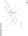
- FIG. 1 shows a horizontal tracker 100 which is already known from the prior art.
- a partial region of a pivot axis 1, which is held by a bearing 4, can be seen.
- the bearing 4 is fastened to a base foundation, here an IPE carrier 5.
- solar modules 2 can be seen, which are attached to the pivot axis 1 by means of module carriers 3.
- the embodiment shown relates to a common design for horizontal trackers 100, the illustrated mounting being repeated several times over the entire length of the pivot axis 1 (not shown here).
- IPE beams 5 or material-saving sheet metal profiles are rammed into a floor surface 6 as floor foundations.
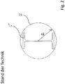
- Figure 2 shows a carrier 5 of the horizontal tracker 100 Figure 1 , Also shown is an enveloping circle 7 for the IPE carrier 5. If ground conditions do not allow the IPE carriers 5 to be rammed directly into a bottom surface 6, corresponding boreholes with an enveloping circle radius R must be drilled in methods known from the prior art. The boreholes are then backfilled and compressed. IPE carriers 5 are then rammed into the backfilled and compressed boreholes. For installation work, this means a lot of additional time and money.
- Figure 3 shows a schematic perspective view of a first embodiment of a support device 10 according to the invention and a first embodiment of a photovoltaic installation 20 according to the invention.
- the photovoltaic installation 20 comprises a multiplicity of solar modules 2, a swivel axis 1 and also a plurality of module carriers 3, by means of which the solar modules 2 are fastened to the swivel axis 1. Furthermore, the photovoltaic installation 20 has a plurality of support devices 10, of which in Figure 3 a support device 10 can be seen. The pivot axis 1 is rotatably received via the bearings 4 of the plurality of support devices 10.
- Support device 10 to be recognized comprises a first support leg SF1 and a second support leg SF2, each of which is anchored in a floor surface 6.
- the first support leg SF1 and the second support leg SF2 are oriented parallel to one another.
- a bridge BB can be seen, which mechanically couples the first support leg SF1 and the second support leg SF2 to one another and keeps them in their relative orientation to one another.
- the pivot axis 1 is received via the bearing 4.
- the bearing 4 is also carried by the bridge BB.
- Both the first support leg SF1 and the second support leg SF2 are detachably connected to the bridge BB or detachably attached to the bridge BB.
- the bearing 4 is also releasably held on the bridge BB or can be removed from the bridge BB.
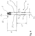
- FIG 4 shows the support device 10 of the embodiment Figure 3 clarifying other aspects.
- a main loading direction FH acts horizontally on the pivot bearing 4 at a height HS, which has the pivot axis 1 with respect to the bottom surface 6.
- the bridge BB mechanically coupling the first and the second support feet SF1 and SF2 converts these loads into compressive and tensile forces FD and FZ, which the first support foot SF1 and the second support foot SF2 introduce into the floor surface 6 at a distance ASF can.
- An embedment depth ET of the first support leg SF1 and the second support leg SF2 can be adapted to the soil conditions.
- first support leg SF1 and the second support leg SF2 each form a thread 13 at their free end region pointing in the direction away from the bridge BB.
- the first support leg SF1 and the second support leg SF2 are off in the embodiment Figure 4 oriented parallel to each other or are made in the embodiment Figure 4 mechanically coupled parallel to each other via the bridge BB.
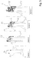
- Figure 5 shows individual steps as they can be provided in a conceivable embodiment of the method according to the invention.
- Step 1 A first support leg SF1 and a second support leg SF2 are introduced into a floor surface 6 at a certain relative distance from one another and anchored in a floor surface 6.
- the support feet SF1 and SF2 anchored in the base surface 6 or introduced into the base surface 6 are then oriented parallel to one another and protrude from the base surface 6 with approximately the same amount of their respective longitudinal extent.
- the support feet SF1 and SF2 each have a thread 13 (cf. Figure 4 ).
- the first support foot SF1 and the second support foot SF2 are screwed into the floor surface 6 for anchoring or for insertion into the floor surface 6.
- Steps 2 and 3 The first support foot SF1 anchored in the floor surface 6 and the second support foot SF2 anchored in the floor surface 6 are mechanically coupled to one another via a bridge BB.
- the bridge BB holds the first support foot 6 anchored in the bottom surface 6 in its relative position relative to the second support foot SF2 anchored in the bottom surface 6.
- Clamping brackets 8a to 8d are provided for the mechanical coupling, by means of which the first support foot SF1 and the second support foot SF2 are fixed to the bridge BB under load.
- Step 4 A bearing 4 is attached to the bridge BB. Step 4 takes place after steps 1 to 3.
- the bearing 4 can be fastened to the bridge BB, for example, by means of screw connections.
- Figure 6 shows a schematic top view of an embodiment of a carrying device 10 with clarification of further aspects.
- the first support leg SF1 and the second support leg SF2 are each designed as hollow tubes and have a circular cross section.
- Figure 6 shows that a circumferential surface of the first support foot SF1 and a circumferential surface of the second support foot SF2 lie along the circumference of the bridge BB by more than 90 ° or at least approximately 180 °.
- the first support leg SF1 and the second support leg SF2 are thus positively received via the bridge BB.
- the first support leg SF1 and the second support leg SF2 are held on the bridge BB by means of the clamping brackets 8a to 8d.
- Figure 7 shows a schematic view of a further embodiment of a carrying device 10 according to the invention.
- the first support leg SF1 and the second support leg SF2 are mechanically coupled to one another by the bridge BB in such a way that the first support leg SF1 and the second support leg SF2 together with the bridge BB have an A-shape form.
- the first support leg SF1 or a longitudinal axis of the first support leg SF1 and the second support leg SF2 or a longitudinal axis of the second support leg SF2 form an angle W which is not less than 15 ° and not greater than 25 °.
- the bridge BB comprises in the exemplary embodiment Figure 7 a two-part molded shell FS, which is formed from mutually corresponding molded shell halves and by means of which molded shell FS the first support leg SF1 and the second support leg SF2 can be received in a form-fitting manner.
- a rotary bearing 4 for a pivot axis 1, not shown, is arranged above the molded shell FS. Since high lateral forces occur in conceivable uses for the carrying device 10 according to the invention, the in FIG Figure 7 shown main load direction FH result. Using the A-shaped support feet SF1 and SF2, the side forces which are introduced to the molded shell FS connecting the support feet SF1 and SF2 can be converted into tensile and compressive forces FZ and FD, so that the entire support device 10 is very stable ,
- Figure 8 shows the embodiment of a support device 10 Figure 7 clarifying other aspects.
- the Figures 8a and 8b different possibilities for setting up or inserting an embodiment of a carrying device 10 according to the invention into a floor surface 6 Fig. 8a the first support leg SF1 and the second support leg SF2 have a large embedment depth ET ', which, for example, due to certain ground conditions Figure 8a may be necessary to set up a photovoltaic system 20 (cf. Figure 3 ) to store stably.
- the large embedment depth ET 'of the support feet SF1 and SF2 in the base surface 6 results in a lower height of the pivot axis HS' and a lower base A SF 'of the support feet SF1 and SF2 in the region of the base surface 6.
- a smaller embedment depth ET "in the base 6 is sufficient, the pivot axis 1 has a larger one Height HS ". This results in a comparison to Fig. 8a larger base A SF "of the support feet SF1 and SF2 in the area of the bottom surface 6.
- a technical effect of the carrying device 10 according to the embodiment Figures 8a and 8b thus consists in that when the distance of the pivot axis 1 from the floor HS 'to HS "increases, the width of the base A SF ' to A SF " also increases. With a variable integration depth of the support feet SF1 and SF2, hardly any changes in the statics are necessary.
- the static conditions of the carrying device 10 remain approximately the same, while in the case of uniform profiles, such as IPE profiles, the limits of the statics are quickly exceeded.
- Figure 9 shows individual steps as they can be provided in a conceivable embodiment of the method according to the invention.
- Figure 9 a method for setting up an embodiment of a support device 10 provided for pivot axes 1 of solar modules 2 according to FIG Figure 7 ,
- Step 1 ' a first support leg SF1 and a second support leg SF2 are screwed into a bottom surface 6 so that they form an angle W of approximately 20 ° with one another.
- the first support leg SF1 and the second support leg SF2 each form a thread 13 (cf. Figure 8 ).
- Step 2 ' the two mold shell halves FS' and FS "are attached to connect the screw foundations SF1 and SF2.
- Step 3 ' The two corresponding mold shell halves FS' and FS "of the bridge BB are screwed together, riveted, or connected in some other way, so that the first support leg SF1 and the second support leg SF2 over the bridge BB or over the two mutually corresponding mold shell halves FS 'and FS "are mechanically coupled to one another.
- Step 4 ' the bearing 4 is attached to the bridge BB or the two mutually corresponding mold shell halves FS' and FS ".
Landscapes
- Engineering & Computer Science (AREA)
- Life Sciences & Earth Sciences (AREA)
- Sustainable Development (AREA)
- Physics & Mathematics (AREA)
- Sustainable Energy (AREA)
- Thermal Sciences (AREA)
- Chemical & Material Sciences (AREA)
- Combustion & Propulsion (AREA)
- Mechanical Engineering (AREA)
- General Engineering & Computer Science (AREA)
- Photovoltaic Devices (AREA)
Claims (15)
- Dispositif support (10), constitué de plusieurs pièces, pour axes de pivotement (1) de modules solaires (2), présentant- au moins un premier pied d'appui (SF1) et au moins un deuxième pied d'appui (SF2), qui sont chacun réalisés pour être ancrés dans une surface d'un sol (6) ;- un pont (BB) qui arrime mécaniquement ledit au moins un premier pied d'appui (SF1) audit au moins un deuxième pied d'appui (SF2) ainsi- qu'une bague (4), qui est réalisée pour loger un axe de pivotement (1),- ladite bague (4) étant portée par le pont (BB) et ledit au moins un premier pied d'appui (SF1) et ledit au moins un deuxième pied d'appui (SF2) étant reliés de manière détachable au pont (BB), et- le pont (BB) arrimant mécaniquement ledit au moins un premier pied d'appui (SF1) audit au moins un deuxième pied d'appui (SF2), en inclinaison l'un vers l'autre,caractérisé en ce que- ledit au moins un premier pied d'appui (SF1) et/ou ledit au moins un deuxième pied d'appui (SF2) réalisent un filetage (13) respectivement à leur zone d'extrémité libre tournée dans le sens opposé au pont (BB).
- Dispositif support selon la revendication 1, comprenant au moins un étrier de serrage (8a, 8b, 8c, 8d) pouvant être fixé au pont (BB), par le biais duquel étrier de serrage ledit au moins un premier pied d'appui (SF1) et/ou ledit au moins un deuxième pied d'appui (SF2) peut/peuvent être rattaché(s) au pont (BB) sous l'application d'une force.
- Dispositif support selon la revendication 2, comprenant au moins un moyen de fixation réalisé de préférence en tant que liaison à vis au moyen de laquelle ledit au moins un étrier de serrage (8a, 8b, 8c, 8d) peut être maintenu dans une position de serrage définie pour le rattachement, sous application d'une force, dudit au moins un premier pied d'appui (SF1) et/ou dudit au moins un deuxième pied d'appui (SF2) au pont (BB).
- Dispositif support selon l'une quelconque des revendications 1 à 3, dans lequel la bague (4) est rattachée au pont (BB) de manière détachable.
- Dispositif support selon la revendication 4, dans lequel la bague (4) est rattachée de manière détachable au pont (BB) par le biais d'au moins une liaison à vis.
- Dispositif support selon l'une quelconque des revendications 1 à 5, dans lequel ledit au moins un premier pied d'appui (SF1) et ledit au moins un deuxième pied d'appui (SF2), avec un arrimage mécanique l'un à l'autre en inclinaison, contiennent un angle qui est fixé entre 0° et 90° et de préférence entre 10° et 35°.
- Dispositif support selon la revendication 6, dans lequel l'angle n'est pas supérieur à 25° et pas inférieur à 15°.
- Dispositif support selon l'une quelconque des revendications précédentes 1 à 7, dans lequel le pont (BB) est réalisé en tant que coque (FS) comprenant au moins deux parties de boîtier, lesquelles au moins deux parties de boîtier fournissent un logement correspondant à la liaison mécanique par complémentarité de forme dudit au moins un premier pied d'appui (SF1) et/ou dudit au moins un deuxième pied d'appui (SF2) à la coque (FS).
- Installation photovoltaïque (20), comprenant une pluralité de modules solaires (2), au moins un axe de pivotement (1) sur lequel sont fixés les modules solaires (2) ainsi que plusieurs dispositifs support (10) selon l'une quelconque ou plusieurs des revendications 1 à 8, ledit au moins un axe de pivotement (1) étant logé par le biais des bagues (4) des dispositifs support (10).
- Procédé d'installation d'un dispositif support (10) prévu pour des axes de pivotement (1) de modules solaires (2), le procédé comprenant les étapes suivantes :- ancrage d'au moins un premier pied d'appui (SF1) dans une surface d'un sol (6),- ancrage d'au moins un deuxième pied d'appui (SF2) dans la surface d'un sol (6),- arrimage mécanique dudit au moins un premier pied d'appui (SF1), ancré dans la surface d'un sol (6), audit au moins un deuxième pied d'appui (SF2), ancré dans la surface d'un sol (6), par un pont (BB) qui porte une bague (4) destinée à loger un axe de pivotement (1) et/ou auquel est fixée une bague (4) destinée à loger un axe de pivotement (1),- ledit pont (BB) arrimant mécaniquement ledit au moins un premier pied d'appui (SF1) audit au moins un deuxième pied d'appui (SF2) en inclinaison l'un vers l'autre, caractérisé en ce que ledit au moins un premier pied d'appui (SF1) et/ou ledit au moins un deuxième pied d'appui (SF2) réalisent chacun un filetage (13) à leur zone d'extrémité libre tournée dans le sens opposé au pont (BB), lequel filetage (13) respectif permet de visser dans la surface d'un sol (6) ledit au moins un premier pied d'appui (SF1) et/ou ledit au moins un deuxième pied d'appui (SF2) pour leur ancrage.
- Procédé selon la revendication 10, dans lequel un étrier de serrage (8a, 8b, 8c, 8d) est rattaché au pont (BB) pour réaliser l'arrimage mécanique, dont il résulte que ledit au moins un premier pied d'appui (SF1) et/ou ledit un deuxième pied d'appui (SF2) est/sont maintenu(s), sous application d'une force, par ledit au moins un étrier de serrage (8a, 8b, 8c, 8d) rattaché au pont (BB).
- Procédé selon l'une quelconque des revendications 10 à 11, dans lequel la bague (4), destinée à loger un axe de pivotement (1), est fixée de manière détachable au pont (BB).
- Procédé selon l'une quelconque des revendications 10 à 12, dans lequel le pont (BB) arrime mécaniquement ledit au moins un premier pied d'appui (SF1) audit au moins un deuxième pied d'appui (SF2) en inclinaison l'un vers l'autre dans un angle d'entre 0° et 90° et de préférence entre 10° et 35°.
- Procédé selon la revendication 13, dans lequel le pont (BB) arrime mécaniquement ledit au moins un premier pied d'appui (SF1) audit au moins un deuxième pied d'appui (SF2) en inclinaison l'un vers l'autre dans un angle qui n'est pas supérieur à 25° et pas inférieur à 15°.
- Procédé selon l'une quelconque des revendications 10 à 14, dans lequel le pont (BB) comprend au moins deux parties de boîtier, lesdites parties de boîtier étant reliées l'une à l'autre pour réaliser le rattachement mécanique et, en même temps, logent en complémentarité de forme ledit au moins un premier pied d'appui (SF1) et/ou ledit au moins un deuxième pied d'appui (SF2).
Applications Claiming Priority (3)
| Application Number | Priority Date | Filing Date | Title |
|---|---|---|---|
| DE202015101195 | 2015-03-10 | ||
| DE202015103930 | 2015-07-27 | ||
| PCT/EP2016/054374 WO2016142227A1 (fr) | 2015-03-10 | 2016-03-02 | Dispositif support pour modules solaires, installation photovoltaïque présentant plusieurs dispositifs support et procédé pour installer un tel dispositif support |
Publications (2)
| Publication Number | Publication Date |
|---|---|
| EP3268678A1 EP3268678A1 (fr) | 2018-01-17 |
| EP3268678B1 true EP3268678B1 (fr) | 2019-12-18 |
Family
ID=55453165
Family Applications (1)
| Application Number | Title | Priority Date | Filing Date |
|---|---|---|---|
| EP16707730.4A Active EP3268678B1 (fr) | 2015-03-10 | 2016-03-02 | Dispositif support pour modules solaires, installation photovoltaïque présentant plusieurs dispositifs support et procédé pour installer un tel dispositif support |
Country Status (6)
| Country | Link |
|---|---|
| US (1) | US20180051915A1 (fr) |
| EP (1) | EP3268678B1 (fr) |
| CN (1) | CN107408915B (fr) |
| ES (1) | ES2777545T3 (fr) |
| MX (1) | MX2017011593A (fr) |
| WO (1) | WO2016142227A1 (fr) |
Families Citing this family (15)
| Publication number | Priority date | Publication date | Assignee | Title |
|---|---|---|---|---|
| US10697490B2 (en) | 2018-07-24 | 2020-06-30 | Ojjo, Inc. | Threaded truss foundations and related systems, methods, and machines |
| US10615739B2 (en) * | 2018-09-05 | 2020-04-07 | Ojjo, Inc. | Optimized truss foundations, adapters for optimized truss foundations, and related systems and methods |
| US11121671B2 (en) * | 2018-09-05 | 2021-09-14 | Ojjo, Inc. | A-frame foundation system for single-axis trackers with weak axis support |
| US11874029B2 (en) * | 2018-09-05 | 2024-01-16 | Ojjo, Inc. | Systems, methods, and machines for joining truss foundation components |
| US10670303B2 (en) * | 2018-10-12 | 2020-06-02 | Ojjo, Inc. | Optimized truss foundations, adapters for optimized truss foundations, and related systems and methods |
| PE20220106A1 (es) * | 2019-03-06 | 2022-01-26 | Ojjo Inc | Adaptadores de cojinetes para seguidores de eje unico |
| US20240136971A1 (en) * | 2019-03-06 | 2024-04-25 | Ojjo, Inc. | Bearing adapters for single-axis trackers. |
| WO2020191238A1 (fr) * | 2019-03-21 | 2020-09-24 | Ojjo, Inc. | Fondations en treillis optimisées par rapport aux moments de suiveurs à axe unique |
| AU2020375921A1 (en) * | 2019-10-29 | 2022-06-16 | Ojjo, Inc. | Adjustable bearing supports for single-axis trackers |
| US11611309B2 (en) * | 2020-02-18 | 2023-03-21 | Ojjo, Inc. | Fixed-tilt solar arrays and related systems |
| US12476577B2 (en) * | 2020-02-27 | 2025-11-18 | Ojjo, Inc. | Truss foundations for frost-heave and other reactive soil environments |
| CA3169755A1 (fr) * | 2020-02-27 | 2021-09-02 | Ojjo, Inc. | Fondations de treillis pour environnements de soulevement par le gel |
| EP4417895B1 (fr) | 2020-09-14 | 2025-11-05 | Nextracker Inc. | Ensemble amortisseur pour dispositifs de poursuite solaires |
| US20220128268A1 (en) * | 2020-10-26 | 2022-04-28 | Ojjo, Inc. | Truss foundations for solar tracker center structures and drive motors |
| US20250385639A1 (en) * | 2024-06-18 | 2025-12-18 | Nextracker Llc | Bearing assemblies and multi-leg frames for solar tracker |
Citations (1)
| Publication number | Priority date | Publication date | Assignee | Title |
|---|---|---|---|---|
| DE202010014899U1 (de) * | 2010-10-29 | 2011-08-22 | Terrafix Gmbh | Verankerungsvorrichtung |
Family Cites Families (7)
| Publication number | Priority date | Publication date | Assignee | Title |
|---|---|---|---|---|
| ATE552615T1 (de) * | 2009-07-29 | 2012-04-15 | Thesan S P A | Solarempfänger für einen solarkonzentrator mit einem linearen brennwinkel |
| KR20110048497A (ko) * | 2011-04-14 | 2011-05-11 | 오쏠라 유한회사 | 태양광 추종이 가능한 태양광 발전 장치 |
| US8939143B2 (en) * | 2011-05-09 | 2015-01-27 | Michael Zuritis | Solar array column cap |
| CA2870487A1 (fr) * | 2012-04-17 | 2013-10-24 | Ronald P. Corio | Ensembles de montage, suiveurs solaires et procedes associes |
| CN203608143U (zh) * | 2013-10-24 | 2014-05-21 | 广东瑞德兴阳光伏科技有限公司 | 一种多立柱式太阳能模组支架结构 |
| ES1119081Y (es) * | 2014-06-03 | 2014-11-11 | Soltec En Renovables Sl | Seguidor solar de un eje |
| CN204190682U (zh) * | 2014-08-28 | 2015-03-04 | 内蒙古科盛太阳能科技有限责任公司 | 太阳能跟踪二维支架及其抱箍结构 |
-
2016
- 2016-03-02 EP EP16707730.4A patent/EP3268678B1/fr active Active
- 2016-03-02 US US15/556,566 patent/US20180051915A1/en not_active Abandoned
- 2016-03-02 ES ES16707730T patent/ES2777545T3/es active Active
- 2016-03-02 CN CN201680007451.5A patent/CN107408915B/zh not_active Expired - Fee Related
- 2016-03-02 WO PCT/EP2016/054374 patent/WO2016142227A1/fr not_active Ceased
- 2016-03-02 MX MX2017011593A patent/MX2017011593A/es unknown
Patent Citations (1)
| Publication number | Priority date | Publication date | Assignee | Title |
|---|---|---|---|---|
| DE202010014899U1 (de) * | 2010-10-29 | 2011-08-22 | Terrafix Gmbh | Verankerungsvorrichtung |
Also Published As
| Publication number | Publication date |
|---|---|
| CN107408915A (zh) | 2017-11-28 |
| MX2017011593A (es) | 2018-07-06 |
| ES2777545T3 (es) | 2020-08-05 |
| CN107408915B (zh) | 2019-08-06 |
| EP3268678A1 (fr) | 2018-01-17 |
| WO2016142227A1 (fr) | 2016-09-15 |
| US20180051915A1 (en) | 2018-02-22 |
Similar Documents
| Publication | Publication Date | Title |
|---|---|---|
| EP3268678B1 (fr) | Dispositif support pour modules solaires, installation photovoltaïque présentant plusieurs dispositifs support et procédé pour installer un tel dispositif support | |
| EP3978826B1 (fr) | Installation photovoltaïque à ancrer dans le sol | |
| EP2385324A2 (fr) | Dispositif destiné à l'élévation de modules solaires | |
| DE2261430A1 (de) | Verfahren und vorrichtung zur gelenkigen verankerung von kraftfahrzeugen an einem tragrahmen zur reparatur oder ueberpruefung von teilen des kraftfahrzeugs | |
| EP2921338B1 (fr) | Mât caténaire pour des installations de caténaire de véhicules électriques de chemin de fer | |
| AT514293B1 (de) | Stützenfuß | |
| WO2018099837A1 (fr) | Élément d'ossature, ossature comprenant un tel élément d'ossature et procédé de montage de l'ossature | |
| WO2020224909A1 (fr) | Support de câble pour un câble d'une installation d'énergie éolienne et procédé | |
| DE9301135U1 (de) | Pfosten für Verkehrsflächen | |
| EP3891386B1 (fr) | Procédé pour réaliser un préserrage du mât d'une éolienne | |
| EP1911884A1 (fr) | Support pour protection contre les chutes de pierres | |
| EP3056611B1 (fr) | Dispositif de couplage destiné à relier une structure porteuse à une fondation au fond de la mer | |
| EP0470296A1 (fr) | Ratelier avec supports en porte à faux | |
| EP3342305A1 (fr) | Support de poteau et procédé de montage d'un support de poteau | |
| DE4435489C2 (de) | Verfahren und Vorrichtung zum Auswechseln eines Hauptdiagonalstabes | |
| WO2016156382A1 (fr) | Système de montage et procédé de montage | |
| DE69701337T2 (de) | Führungsrohr für Kernbrennstabbündel | |
| EP4105160A1 (fr) | Dispositif de retenue | |
| DE202015106538U1 (de) | Trageinrichtung für Stützträger von Solarmodulen | |
| DE102020128157A1 (de) | Arbeitsbühne für ein Bohrrohr sowie Verfahren zur Herstellung eines Bohrpfahls | |
| EP4693889A1 (fr) | Dispositif de retenue et dispositif de fixation de module pour module photovoltaïque ainsi que dispositif de fixation de tige | |
| DE102009029910B4 (de) | Fahrzeug, insbesondere gepanzertes Fahrzeug mit einer die Besatzung des Fahrzeuges aufnehmenden Sicherheitszelle | |
| DE102016204528A1 (de) | Vorrichtung und System zur Verankerung von Aufbauten im Erdboden | |
| DE102023105250A1 (de) | Vorrichtung und Verfahren zur Freiland-Aufstellung von Einzelsolarmodulen und Solarmodulen auf einem Untergrund | |
| DE202024002502U1 (de) | Stiel, Schalungsstütze, Traggerüstteilkombination, Traggerüstrahmen |
Legal Events
| Date | Code | Title | Description |
|---|---|---|---|
| STAA | Information on the status of an ep patent application or granted ep patent |
Free format text: STATUS: THE INTERNATIONAL PUBLICATION HAS BEEN MADE |
|
| PUAI | Public reference made under article 153(3) epc to a published international application that has entered the european phase |
Free format text: ORIGINAL CODE: 0009012 |
|
| STAA | Information on the status of an ep patent application or granted ep patent |
Free format text: STATUS: REQUEST FOR EXAMINATION WAS MADE |
|
| 17P | Request for examination filed |
Effective date: 20171005 |
|
| AK | Designated contracting states |
Kind code of ref document: A1 Designated state(s): AL AT BE BG CH CY CZ DE DK EE ES FI FR GB GR HR HU IE IS IT LI LT LU LV MC MK MT NL NO PL PT RO RS SE SI SK SM TR |
|
| AX | Request for extension of the european patent |
Extension state: BA ME |
|
| RAP1 | Party data changed (applicant data changed or rights of an application transferred) |
Owner name: RAINER, CHRISTIAN |
|
| RIN1 | Information on inventor provided before grant (corrected) |
Inventor name: RAINER, JOHANN |
|
| DAV | Request for validation of the european patent (deleted) | ||
| DAX | Request for extension of the european patent (deleted) | ||
| RIC1 | Information provided on ipc code assigned before grant |
Ipc: F24J 2/54 20181130AFI20160922BHEP |
|
| RIC1 | Information provided on ipc code assigned before grant |
Ipc: F24J 2/54 20060101AFI20160922BHEP |
|
| STAA | Information on the status of an ep patent application or granted ep patent |
Free format text: STATUS: EXAMINATION IS IN PROGRESS |
|
| 17Q | First examination report despatched |
Effective date: 20190225 |
|
| REG | Reference to a national code |
Ref country code: DE Ref legal event code: R079 Ref document number: 502016008048 Country of ref document: DE Free format text: PREVIOUS MAIN CLASS: F24J0002540000 Ipc: F24S0030425000 |
|
| GRAP | Despatch of communication of intention to grant a patent |
Free format text: ORIGINAL CODE: EPIDOSNIGR1 |
|
| STAA | Information on the status of an ep patent application or granted ep patent |
Free format text: STATUS: GRANT OF PATENT IS INTENDED |
|
| RIC1 | Information provided on ipc code assigned before grant |
Ipc: F24S 25/617 20180101ALI20190626BHEP Ipc: F24S 25/10 20180101ALI20190626BHEP Ipc: F24S 30/425 20180101AFI20190626BHEP |
|
| INTG | Intention to grant announced |
Effective date: 20190726 |
|
| GRAS | Grant fee paid |
Free format text: ORIGINAL CODE: EPIDOSNIGR3 |
|
| GRAA | (expected) grant |
Free format text: ORIGINAL CODE: 0009210 |
|
| STAA | Information on the status of an ep patent application or granted ep patent |
Free format text: STATUS: THE PATENT HAS BEEN GRANTED |
|
| AK | Designated contracting states |
Kind code of ref document: B1 Designated state(s): AL AT BE BG CH CY CZ DE DK EE ES FI FR GB GR HR HU IE IS IT LI LT LU LV MC MK MT NL NO PL PT RO RS SE SI SK SM TR |
|
| REG | Reference to a national code |
Ref country code: CH Ref legal event code: EP |
|
| REG | Reference to a national code |
Ref country code: IE Ref legal event code: FG4D Free format text: LANGUAGE OF EP DOCUMENT: GERMAN |
|
| REG | Reference to a national code |
Ref country code: DE Ref legal event code: R096 Ref document number: 502016008048 Country of ref document: DE |
|
| REG | Reference to a national code |
Ref country code: AT Ref legal event code: REF Ref document number: 1215050 Country of ref document: AT Kind code of ref document: T Effective date: 20200115 |
|
| REG | Reference to a national code |
Ref country code: NL Ref legal event code: MP Effective date: 20191218 |
|
| PG25 | Lapsed in a contracting state [announced via postgrant information from national office to epo] |
Ref country code: LV Free format text: LAPSE BECAUSE OF FAILURE TO SUBMIT A TRANSLATION OF THE DESCRIPTION OR TO PAY THE FEE WITHIN THE PRESCRIBED TIME-LIMIT Effective date: 20191218 Ref country code: LT Free format text: LAPSE BECAUSE OF FAILURE TO SUBMIT A TRANSLATION OF THE DESCRIPTION OR TO PAY THE FEE WITHIN THE PRESCRIBED TIME-LIMIT Effective date: 20191218 Ref country code: BG Free format text: LAPSE BECAUSE OF FAILURE TO SUBMIT A TRANSLATION OF THE DESCRIPTION OR TO PAY THE FEE WITHIN THE PRESCRIBED TIME-LIMIT Effective date: 20200318 Ref country code: NO Free format text: LAPSE BECAUSE OF FAILURE TO SUBMIT A TRANSLATION OF THE DESCRIPTION OR TO PAY THE FEE WITHIN THE PRESCRIBED TIME-LIMIT Effective date: 20200318 Ref country code: GR Free format text: LAPSE BECAUSE OF FAILURE TO SUBMIT A TRANSLATION OF THE DESCRIPTION OR TO PAY THE FEE WITHIN THE PRESCRIBED TIME-LIMIT Effective date: 20200319 Ref country code: SE Free format text: LAPSE BECAUSE OF FAILURE TO SUBMIT A TRANSLATION OF THE DESCRIPTION OR TO PAY THE FEE WITHIN THE PRESCRIBED TIME-LIMIT Effective date: 20191218 Ref country code: FI Free format text: LAPSE BECAUSE OF FAILURE TO SUBMIT A TRANSLATION OF THE DESCRIPTION OR TO PAY THE FEE WITHIN THE PRESCRIBED TIME-LIMIT Effective date: 20191218 |
|
| PGFP | Annual fee paid to national office [announced via postgrant information from national office to epo] |
Ref country code: DE Payment date: 20200320 Year of fee payment: 5 |
|
| REG | Reference to a national code |
Ref country code: LT Ref legal event code: MG4D |
|
| PG25 | Lapsed in a contracting state [announced via postgrant information from national office to epo] |
Ref country code: RS Free format text: LAPSE BECAUSE OF FAILURE TO SUBMIT A TRANSLATION OF THE DESCRIPTION OR TO PAY THE FEE WITHIN THE PRESCRIBED TIME-LIMIT Effective date: 20191218 Ref country code: HR Free format text: LAPSE BECAUSE OF FAILURE TO SUBMIT A TRANSLATION OF THE DESCRIPTION OR TO PAY THE FEE WITHIN THE PRESCRIBED TIME-LIMIT Effective date: 20191218 |
|
| PG25 | Lapsed in a contracting state [announced via postgrant information from national office to epo] |
Ref country code: AL Free format text: LAPSE BECAUSE OF FAILURE TO SUBMIT A TRANSLATION OF THE DESCRIPTION OR TO PAY THE FEE WITHIN THE PRESCRIBED TIME-LIMIT Effective date: 20191218 |
|
| PGFP | Annual fee paid to national office [announced via postgrant information from national office to epo] |
Ref country code: FR Payment date: 20200320 Year of fee payment: 5 |
|
| PG25 | Lapsed in a contracting state [announced via postgrant information from national office to epo] |
Ref country code: EE Free format text: LAPSE BECAUSE OF FAILURE TO SUBMIT A TRANSLATION OF THE DESCRIPTION OR TO PAY THE FEE WITHIN THE PRESCRIBED TIME-LIMIT Effective date: 20191218 Ref country code: RO Free format text: LAPSE BECAUSE OF FAILURE TO SUBMIT A TRANSLATION OF THE DESCRIPTION OR TO PAY THE FEE WITHIN THE PRESCRIBED TIME-LIMIT Effective date: 20191218 Ref country code: PT Free format text: LAPSE BECAUSE OF FAILURE TO SUBMIT A TRANSLATION OF THE DESCRIPTION OR TO PAY THE FEE WITHIN THE PRESCRIBED TIME-LIMIT Effective date: 20200513 Ref country code: CZ Free format text: LAPSE BECAUSE OF FAILURE TO SUBMIT A TRANSLATION OF THE DESCRIPTION OR TO PAY THE FEE WITHIN THE PRESCRIBED TIME-LIMIT Effective date: 20191218 Ref country code: NL Free format text: LAPSE BECAUSE OF FAILURE TO SUBMIT A TRANSLATION OF THE DESCRIPTION OR TO PAY THE FEE WITHIN THE PRESCRIBED TIME-LIMIT Effective date: 20191218 |
|
| PGFP | Annual fee paid to national office [announced via postgrant information from national office to epo] |
Ref country code: ES Payment date: 20200522 Year of fee payment: 5 |
|
| REG | Reference to a national code |
Ref country code: ES Ref legal event code: FG2A Ref document number: 2777545 Country of ref document: ES Kind code of ref document: T3 Effective date: 20200805 |
|
| PG25 | Lapsed in a contracting state [announced via postgrant information from national office to epo] |
Ref country code: SM Free format text: LAPSE BECAUSE OF FAILURE TO SUBMIT A TRANSLATION OF THE DESCRIPTION OR TO PAY THE FEE WITHIN THE PRESCRIBED TIME-LIMIT Effective date: 20191218 Ref country code: IS Free format text: LAPSE BECAUSE OF FAILURE TO SUBMIT A TRANSLATION OF THE DESCRIPTION OR TO PAY THE FEE WITHIN THE PRESCRIBED TIME-LIMIT Effective date: 20200418 Ref country code: SK Free format text: LAPSE BECAUSE OF FAILURE TO SUBMIT A TRANSLATION OF THE DESCRIPTION OR TO PAY THE FEE WITHIN THE PRESCRIBED TIME-LIMIT Effective date: 20191218 |
|
| REG | Reference to a national code |
Ref country code: DE Ref legal event code: R097 Ref document number: 502016008048 Country of ref document: DE |
|
| PLBE | No opposition filed within time limit |
Free format text: ORIGINAL CODE: 0009261 |
|
| STAA | Information on the status of an ep patent application or granted ep patent |
Free format text: STATUS: NO OPPOSITION FILED WITHIN TIME LIMIT |
|
| PG25 | Lapsed in a contracting state [announced via postgrant information from national office to epo] |
Ref country code: MC Free format text: LAPSE BECAUSE OF FAILURE TO SUBMIT A TRANSLATION OF THE DESCRIPTION OR TO PAY THE FEE WITHIN THE PRESCRIBED TIME-LIMIT Effective date: 20191218 Ref country code: DK Free format text: LAPSE BECAUSE OF FAILURE TO SUBMIT A TRANSLATION OF THE DESCRIPTION OR TO PAY THE FEE WITHIN THE PRESCRIBED TIME-LIMIT Effective date: 20191218 |
|
| REG | Reference to a national code |
Ref country code: CH Ref legal event code: PL |
|
| 26N | No opposition filed |
Effective date: 20200921 |
|
| PG25 | Lapsed in a contracting state [announced via postgrant information from national office to epo] |
Ref country code: SI Free format text: LAPSE BECAUSE OF FAILURE TO SUBMIT A TRANSLATION OF THE DESCRIPTION OR TO PAY THE FEE WITHIN THE PRESCRIBED TIME-LIMIT Effective date: 20191218 |
|
| REG | Reference to a national code |
Ref country code: BE Ref legal event code: MM Effective date: 20200331 |
|
| PG25 | Lapsed in a contracting state [announced via postgrant information from national office to epo] |
Ref country code: LU Free format text: LAPSE BECAUSE OF NON-PAYMENT OF DUE FEES Effective date: 20200302 |
|
| PG25 | Lapsed in a contracting state [announced via postgrant information from national office to epo] |
Ref country code: IE Free format text: LAPSE BECAUSE OF NON-PAYMENT OF DUE FEES Effective date: 20200302 Ref country code: LI Free format text: LAPSE BECAUSE OF NON-PAYMENT OF DUE FEES Effective date: 20200331 Ref country code: CH Free format text: LAPSE BECAUSE OF NON-PAYMENT OF DUE FEES Effective date: 20200331 Ref country code: IT Free format text: LAPSE BECAUSE OF FAILURE TO SUBMIT A TRANSLATION OF THE DESCRIPTION OR TO PAY THE FEE WITHIN THE PRESCRIBED TIME-LIMIT Effective date: 20191218 |
|
| PG25 | Lapsed in a contracting state [announced via postgrant information from national office to epo] |
Ref country code: PL Free format text: LAPSE BECAUSE OF FAILURE TO SUBMIT A TRANSLATION OF THE DESCRIPTION OR TO PAY THE FEE WITHIN THE PRESCRIBED TIME-LIMIT Effective date: 20191218 Ref country code: BE Free format text: LAPSE BECAUSE OF NON-PAYMENT OF DUE FEES Effective date: 20200331 |
|
| GBPC | Gb: european patent ceased through non-payment of renewal fee |
Effective date: 20200318 |
|
| PG25 | Lapsed in a contracting state [announced via postgrant information from national office to epo] |
Ref country code: GB Free format text: LAPSE BECAUSE OF NON-PAYMENT OF DUE FEES Effective date: 20200318 |
|
| REG | Reference to a national code |
Ref country code: DE Ref legal event code: R119 Ref document number: 502016008048 Country of ref document: DE |
|
| PG25 | Lapsed in a contracting state [announced via postgrant information from national office to epo] |
Ref country code: FR Free format text: LAPSE BECAUSE OF NON-PAYMENT OF DUE FEES Effective date: 20210331 Ref country code: DE Free format text: LAPSE BECAUSE OF NON-PAYMENT OF DUE FEES Effective date: 20211001 |
|
| REG | Reference to a national code |
Ref country code: AT Ref legal event code: MM01 Ref document number: 1215050 Country of ref document: AT Kind code of ref document: T Effective date: 20210302 |
|
| REG | Reference to a national code |
Ref country code: ES Ref legal event code: FD2A Effective date: 20220517 |
|
| PG25 | Lapsed in a contracting state [announced via postgrant information from national office to epo] |
Ref country code: TR Free format text: LAPSE BECAUSE OF FAILURE TO SUBMIT A TRANSLATION OF THE DESCRIPTION OR TO PAY THE FEE WITHIN THE PRESCRIBED TIME-LIMIT Effective date: 20191218 Ref country code: MT Free format text: LAPSE BECAUSE OF FAILURE TO SUBMIT A TRANSLATION OF THE DESCRIPTION OR TO PAY THE FEE WITHIN THE PRESCRIBED TIME-LIMIT Effective date: 20191218 Ref country code: CY Free format text: LAPSE BECAUSE OF FAILURE TO SUBMIT A TRANSLATION OF THE DESCRIPTION OR TO PAY THE FEE WITHIN THE PRESCRIBED TIME-LIMIT Effective date: 20191218 |
|
| PG25 | Lapsed in a contracting state [announced via postgrant information from national office to epo] |
Ref country code: MK Free format text: LAPSE BECAUSE OF FAILURE TO SUBMIT A TRANSLATION OF THE DESCRIPTION OR TO PAY THE FEE WITHIN THE PRESCRIBED TIME-LIMIT Effective date: 20191218 |
|
| PG25 | Lapsed in a contracting state [announced via postgrant information from national office to epo] |
Ref country code: ES Free format text: LAPSE BECAUSE OF NON-PAYMENT OF DUE FEES Effective date: 20210303 |
|
| PG25 | Lapsed in a contracting state [announced via postgrant information from national office to epo] |
Ref country code: AT Free format text: LAPSE BECAUSE OF NON-PAYMENT OF DUE FEES Effective date: 20210302 |