EP3268954B1 - Anordnung und feldgerät der prozessmesstechnik - Google Patents
Anordnung und feldgerät der prozessmesstechnik Download PDFInfo
- Publication number
- EP3268954B1 EP3268954B1 EP16704442.9A EP16704442A EP3268954B1 EP 3268954 B1 EP3268954 B1 EP 3268954B1 EP 16704442 A EP16704442 A EP 16704442A EP 3268954 B1 EP3268954 B1 EP 3268954B1
- Authority
- EP
- European Patent Office
- Prior art keywords
- arrangement
- damping element
- natural frequency
- annular
- frequency
- Prior art date
- Legal status (The legal status is an assumption and is not a legal conclusion. Google has not performed a legal analysis and makes no representation as to the accuracy of the status listed.)
- Active
Links
Images


Classifications
-
- G—PHYSICS
- G10—MUSICAL INSTRUMENTS; ACOUSTICS
- G10K—SOUND-PRODUCING DEVICES; METHODS OR DEVICES FOR PROTECTING AGAINST, OR FOR DAMPING, NOISE OR OTHER ACOUSTIC WAVES IN GENERAL; ACOUSTICS NOT OTHERWISE PROVIDED FOR
- G10K1/00—Devices in which sound is produced by striking a resonating body, e.g. bells, chimes or gongs
- G10K1/06—Devices in which sound is produced by striking a resonating body, e.g. bells, chimes or gongs the resonating devices having the shape of a bell, plate, rod, or tube
- G10K1/062—Devices in which sound is produced by striking a resonating body, e.g. bells, chimes or gongs the resonating devices having the shape of a bell, plate, rod, or tube electrically operated
- G10K1/066—Devices in which sound is produced by striking a resonating body, e.g. bells, chimes or gongs the resonating devices having the shape of a bell, plate, rod, or tube electrically operated the sounding member being a tube, plate or rod
-
- G—PHYSICS
- G10—MUSICAL INSTRUMENTS; ACOUSTICS
- G10K—SOUND-PRODUCING DEVICES; METHODS OR DEVICES FOR PROTECTING AGAINST, OR FOR DAMPING, NOISE OR OTHER ACOUSTIC WAVES IN GENERAL; ACOUSTICS NOT OTHERWISE PROVIDED FOR
- G10K1/00—Devices in which sound is produced by striking a resonating body, e.g. bells, chimes or gongs
- G10K1/06—Devices in which sound is produced by striking a resonating body, e.g. bells, chimes or gongs the resonating devices having the shape of a bell, plate, rod, or tube
- G10K1/08—Details or accessories of general applicability
-
- G—PHYSICS
- G10—MUSICAL INSTRUMENTS; ACOUSTICS
- G10K—SOUND-PRODUCING DEVICES; METHODS OR DEVICES FOR PROTECTING AGAINST, OR FOR DAMPING, NOISE OR OTHER ACOUSTIC WAVES IN GENERAL; ACOUSTICS NOT OTHERWISE PROVIDED FOR
- G10K11/00—Methods or devices for transmitting, conducting or directing sound in general; Methods or devices for protecting against, or for damping, noise or other acoustic waves in general
- G10K11/002—Devices for damping, suppressing, obstructing or conducting sound in acoustic devices
-
- G—PHYSICS
- G10—MUSICAL INSTRUMENTS; ACOUSTICS
- G10K—SOUND-PRODUCING DEVICES; METHODS OR DEVICES FOR PROTECTING AGAINST, OR FOR DAMPING, NOISE OR OTHER ACOUSTIC WAVES IN GENERAL; ACOUSTICS NOT OTHERWISE PROVIDED FOR
- G10K11/00—Methods or devices for transmitting, conducting or directing sound in general; Methods or devices for protecting against, or for damping, noise or other acoustic waves in general
- G10K11/02—Mechanical acoustic impedances; Impedance matching, e.g. by horns; Acoustic resonators
- G10K11/04—Acoustic filters ; Acoustic resonators
Definitions
- the present invention solves this problem by a device having the features of claim 1.
- An inventive arrangement comprises an ultrasonic transducer and a damping element, or a bandpass filter, with a longitudinal axis L.
- An ultrasonic transducer is limited in this respect not only to piezoelectric elements or other ultrasound generating elements but may also include the region of the arrangement, which the ultrasonic signal before entering the medium must cross. This may include, for example, one or more coupling layers or matching layers.
- a metallic attachment may be part of the ultrasonic transducer from which an ultrasonic signal is emitted into a gaseous or liquid medium. Particularly preferably, this metallic attachment is connected by means of a joint with the damping element.
- the damping element connects the ultrasonic transducer with a housing or Meßrohrwandung.
- this wall is not part of the arrangement.
- the transducer has an attachment with a wetted surface.
- Ultrasonic signals are emitted from the surface into a gaseous or liquid medium.
- This can be a measuring medium in the case of a flow meter or, for example, in level measurement. Air.
- the damping element has at least two annular grooves and a ring-shaped segment arranged therebetween.
- An annular segment is an annular trained circumferential projection.
- the annular mass segment always has the same wall thickness along its circumference.
- the damping element has a first natural frequency f a , in which the annular mass segment performs an axial movement parallel to the longitudinal direction of the damping element. This can also be called axial mode. If the damping element has a plurality of axial modes, then the first natural frequency is to be understood as the highest natural frequency at which the annular mass segment carries out an axial movement parallel to the longitudinal direction of the damping element.
- damping element according to the invention has a second natural frequency f r , in which the annular mass segment performs a rotational movement, preferably around its center of mass. This can also be called rotation mode. If the damping element has a plurality of rotational modes, the first natural frequency to be understood as the lowest natural frequency at which the annular mass segment carries out a rotational movement.
- the ratio of the first natural frequency f a to the second natural frequency f r is smaller than 0.75 according to the invention. This arrangement allows selection of the useful frequency over a very wide frequency range. Advantageous embodiments are the subject of the dependent claims. It is advantageous if the ratio of the first natural frequency f a to the second natural frequency f r is less than 0.55, particularly preferably less than 0.4.
- the damping element has a first mean distance r 2 from the outer wall of a hollow-cylindrical partial region to the longitudinal axis L.
- the averaging of the distance relates to a distance averaged over the circumference and the length of the annular groove. Thus, individual areas may deviate from the mean.
- the damping element has a second average distance r 1 from the inner wall of the hollow cylindrical partial region to the longitudinal axis L.
- the averaging of the distance refers to a distance of the inner wall to the longitudinal axis averaged over the circumference and the length of the annular groove.
- this term is 0.093 r 2 - r 1 1 mm + 0.0016 l 3 1 mm - 12.5 2 + 0.057 less than 0.55, and is more preferably less than 0.40.
- the data for r 1 , r 2 and l 3 must be given in millimeters.
- the ultrasonic transducer and the damping element are connected to one another in a material-locking manner.
- the damping element has less than 5 annular grooves. An increasing number of annular grooves means an increasing danger of weak points which can fail under pressure loads and under structure-borne sound vibrations.
- the length of the at least two annular grooves in the axial direction is the same length and that the length of the annular segment is greater, preferably at least 1.5 times as large as the length of one of the two annular grooves. Due to the design of the ring segment segment over a large longitudinal range of time, the structure-borne noise can be better erased and at the same time there is a better splitting between axial modes and rotational modes in the frequency spectrum. It is advantageous if the ultrasonic transducer terminally a bending plate having a surface from which the ultrasonic signal is emitted into the medium, which Bending plate edge free swinging is formed.
- the bending plate is described as a plate having the surface from which the ultrasonic signal is radiated into a medium.
- EP 1 340 964 B1 takes place in this embodiment, no edge feed of structure-borne noise by a bending plate in the damping element, but the bending plate is free swinging edge.
- the ultrasonic signal can advantageously be transmitted over a large area into the gaseous or liquid medium.
- the arrangement in a frequency range in which the ratio of the useful frequency to the first natural frequency is greater than 1.6 and in which the ratio of the useful frequency to the second natural frequency is less than 0.7 has no axial or rotational natural frequency ,
- the arrangement can not have an axial or rotational natural frequency in the range between 50,000 and 120,000 hearts.
- a field device of process measuring technology, in particular an ultrasonic flowmeter for measuring gaseous media, has a measuring tube to which an arrangement according to claim 1 is attached.
- the arrangement can also be used in a level gauge, wherein the measuring tube but usually by a storage vessel -. a tank or a silo is replaced.
- the present arrangement can be used both in level gauges and in flow meters.
- the structure, the mode of operation and the resulting advantages will be described primarily for an ultrasonic flowmeter.
- the arguments can mainly be transferred to ultrasonic level measurement.
- Ultrasonic flowmeters are widely used in process and automation technology. They allow in a simple way to determine the volume flow and / or mass flow of a medium to be measured in a pipeline.
- the known ultrasonic flowmeters often work according to the transit time difference principle.
- the transit time difference principle the different transit times of ultrasonic waves, in particular ultrasonic pulses, so-called bursts, are evaluated relative to the flow direction of the liquid.
- ultrasonic pulses at a certain angle to Tube axis sent both with and against the flow. From the transit time difference, the flow rate and thus with a known diameter of the pipe section of the volume flow can be determined.
- ultrasonic waves are generated or received with the help of so-called ultrasonic transducers.
- ultrasonic transducers are firmly connected to the pipe wall of the respective pipe section.
- This type of device is also known in professional circles as an inline ultrasonic flowmeter.
- Clamp-on ultrasonic flow measurement systems are also available which are externally attached to the measuring tube, e.g. be unbolted.
- clamp-on ultrasonic flowmeters are not the subject of the present invention
- the ultrasonic transducers normally comprise an electromechanical transducer element, e.g. one or more piezoelectric elements
- the ultrasonic transducers are arranged in a common plane on the measuring tube, either on opposite sides of the measuring tube, then the acoustic signal, projected on a tube cross-section, once along a secant through the measuring tube , or on the same side of the measuring tube, then the acoustic signal is reflected on the opposite side of the measuring tube, whereby the acoustic signal passes twice through the measuring tube along the projected on the cross section through the measuring tube secant.
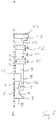
- Fig. 1 In the concrete embodiment of the Fig. 1 is an arrangement with a corresponding ultrasonic transducer 1 with two superposed electromechanical transducer elements 2, in particular with two piezo elements configured.
- the ultrasonic transducer 1 also has an attachment 4 with a surface 5 in contact with the medium. At this surface 5, the ultrasonic waves generated by the one or more electromechanical transducer elements 2 are delivered to the measuring medium.
- the in Fig. 1 shown essay 4 has a base 6, which is in contact, in particular in positive contact with the electromechanical transducer elements 2. Furthermore, the article 4 on a bending plate 7 on with the medium-contacting surface 5.
- the base 6 of the attachment 4 has an interface 16 to a damping element 15.
- This damping element 15 is formed as a cylindrical body with at least two mutually parallel annular grooves 10 and 12.
- the interface 16 may e.g. be designed as a welded joint.
- a first annular mass segment 9 is arranged, which has a greater wall thickness, in particular at least twice as thick a wall thickness as the annular groove 10.
- a second ring segment 11 is also arranged, which has a greater wall thickness, in particular at least twice as thick wall thickness, as the annular grooves 10 and 12th
- the damping element 15 is essentially defined by three radii. It is provided a first radius r 1 , which extends from a longitudinal axis L of the damping element 15 to an inner wall of the cylindrical body. Furthermore, a second radius r 2 is provided, which describes the distance of the outer wall in the region of the annular grooves 10, 12 to the longitudinal axis. Finally, a third radius r 3 is provided which describes the radial distance between the longitudinal axis and the outermost point of the second annular segment 11.
- the damping element 15 is connected via an interface 17 in the region of the third radius r 3 with a housing wall 14.
- the interface 17 may be formed as a welded joint.
- the interface is in Fig. 1 arranged on radially outside of the second radius r 2 and in the region of the third radius r 3 .
- the annular grooves 10 and 12 extend over a respective longitudinal section l 1 and l 2 along the longitudinal axis L. These longitudinal sections l 1 and l 2 are in Fig. 1 the same size.
- the second ring mass segment 11 extends over a longitudinal section l 3 , which in the embodiment of the Fig. 1 is greater than the lengths l 1 and l 2 .
- the first annular mass segment 9 is connected at its radially outermost point with a ring segment 8, which extends from the interface 16 to the ring mass 9.
- This ring segment 8 has a smaller, preferably at least twice as small wall thickness as the first annular mass segment 9.
- the Ringmassesegment 9 goes over at its radially innermost point in the annular groove. As a result, upon the application of an axial force, a deflection of this force through the annular mass segment takes place from outside to inside.
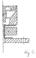
- Fig. 2 shows a damping element of the prior art of EP 1 340 964 B1 , The damping behavior of this damping element was investigated and with the damping behavior of the damping behavior of the arrangement of Fig. 1 compared.
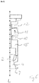
- Fig. 3 shows on the basis of the spectrum S1 with the solid line vibration spectra, the damping behavior of the arrangement of Fig. 1 in comparison with the spectrum S2 with the dashed line to the damping behavior of the arrangement of Fig. 2 ,
- a useful signal An which is needed to determine the level or the flow, is in the spectrum S1 at about 8200 Hz.
- the frequency range of the useful signal An for the arrangement of Fig. 1 be chosen in a very wide range.
- the frequency range of the useful signal can be selected arbitrarily in the range between 45,000 to about 120,000 Hz, without resulting in larger superimpositions of the useful signal An with the natural frequencies A-a1, A-a2, A-r1 of the damping element 15.
- the peaks in spectrum S1 at 28,000 and at 35,000 Hz represent axial vibrations, while the peak at about 136,000 Hz represents a rotational vibration.
- the spectrum of the damping element of the Fig. 2 true to scale implementation a whole series of natural oscillations, which overlap with a useful signal at about 82000 Hz.
- the peaks at 25000 and at 55000 Hz represent axial vibrations B-a1 and B-a2.
- the peaks at 71000 and 73000 Hz, on the other hand, represent rotational vibrations B-r1 and B-r2.
- Both the axial and the Rotational vibrations are in the in Fig. 3 variant shown below the useful frequency of 82000 Hz.
- Fig. 4 shows the vibration behavior of the damping element when transmitting and / or receiving an ultrasonic signal in the useful frequency range. It can be seen that predominantly the ultrasonic transducer 1, ie the electromechanical transducer elements 2 and 3 and the attachment 4 with the base 6 and the bending plate 7, are in vibration.
- the bending plate 7 has a radial deflection A1 during operation of the ultrasonic flow device. However, this deflection A1 is not transmitted to a subsequent damping structure, but the bending plate 7 is free-swinging and is not disturbed in its radial deflection by a damping structure. As a result, the radiated ultrasound signal is transmitted to the medium particularly well and unhindered.
- Fig. 5 shows the vibration behavior of the arrangement according to the invention in the illustrated embodiment according to Fig. 1 in the state of natural frequency A-a2 (axial mode at about 35000 Hz.).
- the annular mass segment 11 performs an axial movement between the two parallel annular grooves 10 and 12.
- the up and down movement of the ring gauge segment 11 results in a temporary deformation of the material wall in the region of the annular grooves 10 and 12 in the form of a temporary thinning or thickening.
- Fig. 6 shows the vibration behavior of the arrangement according to the invention in the illustrated embodiment according to Fig. 1 in the state of natural frequency A-r1 (rotation mode at about 137000 Hz.).
- the annular mass segment 11 performs a rotational movement between the two parallel annular grooves 10 and 12. Due to the oscillatory movement of the annular segment 11, there is a temporary material wall deformation in the region of the annular grooves 10 and 12 in the form of a wave-shaped bending of the material wall.
- Fig. 1 illustrated embodiment can be further modified within the scope of the invention.
- a prismatic basic structure is also possible, preferably with uniform prism surfaces.
- Individual segments of the basic structure, in particular also the annular mass segment 11, can be made polygonal in a two-dimensional section perpendicular to the longitudinal axis L.
- the damping element and the attachment are rotationally symmetrical and consist of metal.
- the attachment may preferably consist of stainless steel or titanium.
- the damping element is preferably made of stainless steel.
Landscapes
- Physics & Mathematics (AREA)
- Engineering & Computer Science (AREA)
- Acoustics & Sound (AREA)
- Multimedia (AREA)
- Measuring Volume Flow (AREA)
- Transducers For Ultrasonic Waves (AREA)
Description
- Es ist eine Anordnung eines Ultraschallwandlers mit einem Filterelement aus der
EP 1 340 964 B1 bekannt. Diese Anordnung weist allerdings eine signalabstrahlende Biegeplatte auf, welche randseitig den Körperschall in das Filterelement einspeist. Dadurch wird das Ultraschallsignal zwar in der Mitte zentriert, allerdings ist die abstrahlende Fläche sehr gering. Der konstruktive Gesamtaufbau der Anordnung in dieser Druckschrift zeigt zudem ein Frequenzspektrum, in welchem Rotations- und Axialmoden sehr nahe beieinander liegen und unterhalb eines Frequenzbereichs von 80000 Hz, dem üblichen Frequenzbereich des Nutzsignals. Das bedeutet, dass die Wahl der Frequenz für das Nutzsignal äußerst eingeschränkt ist oder man einen Messfehler, hervorgerufen durch die Eigenfrequenzen, kompensieren muss. - Ausgehend von diesem Stand der Technik ist es nunmehr Aufgabe der vorliegenden Erfindung eine Anordnung bereitzustellen, mit einem breiten Frequenzbereich für das Nutzsignal, ohne dass eine Kompensation eines Messfehlers notwendig ist.
- Die vorliegende Erfindung löst diese Aufgabe durch eine Vorrichtung mit den Merkmalen des Anspruchs 1.
- Vorteilhafte Ausgestaltungen der Erfindung sind Gegenstand der Unteransprüche.
- Eine erfindungsgemäße Anordnung umfasst einen Ultraschallwandler und ein Dämpfungselement, bzw. einen Bandpassfilter, mit einer Längsachse L. Ein Ultraschallwandler beschränkt sich diesbezüglich nicht ausschließlich auf Piezoelemente oder andere ultraschallerzeugende Elemente sondern kann auch den Bereich der Anordnung umfassen, welchen das Ultraschallsignal vor Eintritt in das Medium durchqueren muss. Dies kann z.B. eine oder mehrere Koppelschichten oder Anpassungsschichten umfassen. Besonders bevorzugt kann z.B. ein metallischer Aufsatz Teil des Ultraschallwandlers sein, von welchem aus ein Ultraschallsignal in ein gasförmiges oder flüssiges Medium ausgesandt wird. Besonders bevorzugt ist dieser metallische Aufsatz mittels einer Fügestelle mit dem Dämpfungselement verbunden.
- Weiterhin erfindungsgemäß verbindet das Dämpfungselement den Ultraschallwandler mit einer Gehäuse- oder Messrohrwandung. Diese Wandung ist dabei jedoch nicht Teil der Anordnung. Der Wandler weist einen Aufsatz mit einer mediumsberührenden Oberfläche auf.
- Von der Oberfläche werden Ultraschallsignale in ein gasförmiges oder flüssiges Medium ausgesandt. Dies kann im Fall eines Durchflussmessgerätes ein Messmedium sein oder bei der Füllstandsmessung z.B. Luft.
- Das Dämpfungselement weist zumindest zwei Ringnuten und ein dazwischen angeordnetes Ringmassesegment auf. Ein Ringmassesegment ist ein ringförmig ausgebildeter umlaufender Vorsprung. In einer bevorzugten Ausführungsvariante weist das Ringmassesegment entlang seines Umfangs stets die gleiche Wandstärke auf.
- Weiterhin erfindungsgemäß weist Dämpfungselement eine erste Eigenfrequenz fa aufweist, in welcher das Ringmassesegment eine Axialbewegung parallel zur Längsrichtung des Dämpfungselements ausführt. Dies kann auch Axialmode genannt werden. Falls das Dämpfungselement mehrere Axialmoden aufweist, so ist als erste Eigenfrequenz die höchste Eigenfrequenz zu verstehen, bei welcher das Ringmassesegment eine Axialbewegung parallel zur Längsrichtung des Dämpfungselements ausführt.
- Zudem weist Dämpfungselement erfindungsgemäß ein zweite Eigenfrequenz fr auf, in welcher das Ringmassesegment eine Rotationsbewegung, vorzugsweise um seinen Masseschwerpunkt, ausführt. Dies kann auch Rotationsmode genannt werden. Falls das Dämpfungselement mehrere Rotationsmoden aufweist, so ist als erste Eigenfrequenz die niedrigste Eigenfrequenz zu verstehen, bei welcher das Ringmassesegment eine Rotationsbewegung ausführt.
- Das Verhältnis der ersten Eigenfrequenz fa zur zweiten Eigenfrequenz fr ist erfindungsgemäß kleiner als 0,75.
Diese Anordnung ermöglicht eine Auswahl der Nutzfrequenz über einen sehr breiten Frequenzbereich.
Vorteilhafte Ausgestaltungen sind Gegenstand der Unteransprüche.
Es ist von Vorteil, wenn das Verhältnis der ersten Eigenfrequenz fa zur zweiten Eigenfrequenz fr kleiner ist als 0,55, besonders bevorzugt kleiner ist als 0,4. - Das Dämpfungselement weist zumindest im Bereich einer ersten der zumindest zwei Ringnuten einen ersten mittleren Abstand r2 von der Außenwandung eines hohlzylindrischen Teilbereichs bis zur Längsachse L auf. Die Mittelung des Abstandes bezieht sich auf einen Abstand gemittelt über den Umfang und die Länge der Ringnut. So können einzelne Bereiche vom Mittelwert abweichen.
Das Dämpfungselement weist zumindest im Bereich der ersten der zumindest zwei Ringnuten einen zweiten mittleren Abstand r1 von der Innenwandung des hohlzylindrischen Teilbereichs bis zur Längsachse L auf. Auch hierbei bezieht sich die Mittelung des Abstandes auf einen Abstand der Innenwandung zur Längsachse gemittelt über den Umfang und die Länge der Ringnut.
Außerdem weist das Ringmassesegment zwischen den beiden Ringnuten eine gewisse Länge l3 in axialer Richtung auf. Diese Länge ist ebenfalls über die Länge und den Umfang gemittelt.
Diese Größen sind in einem mathematischen Ausdruck zusammengefasst und zueinander ins Verhältnis gesetzt. Nach der vorliegenden Erfindung ist dieser Ausdruck
Durch diese bauliche Abstimmung einzelner Segmente des Dämpfungselements kann eine weitere Optimierung des Frequenzspektrums der Anordnung erreicht werden.
Es ist zudem von Vorteil wenn der hohlzylindrische Teilbereich rotationssymmetrisch ist. Dadurch erfolgt eine gleichmäßige Belastung und Auslöschung des Körperschalls.
Es ist von Vorteil, wenn der Ultraschallwandler und das Dämpfungselement stoffschlüssig miteinander verbunden sind. Es sind zwar auch Schraubvarianten für Ultraschallwandler und Dämpfungselemente bekannt, diese können sich allerdings unter Schwingungen lösen oder verformen und sind meist keine hygienische Lösung.
Es ist weiterhin von Vorteil, wenn das Dämpfungselement weniger als 5 Ringnuten aufweist. Eine zunehmende Anzahl von Ringnuten bedeutet eine zunehmende Gefahr von Schwachstellen welche bei Druckbelastungen und unter Körperschallschwingungen versagen können.
Es ist von Vorteil, wenn die Länge der zumindest zwei Ringnuten in axialer Richtung gleich lang ist und dass die Länge des Ringmassesegments größer, vorzugsweise zumindest 1,5 mal so groß ist, wie die Länge einer der zwei Ringnuten. Durch die Ausgestaltung des Ringmassesegments über einen großen Längsbereich hinweg kann der Körperschall besser ausgelöscht werden und zugleich eine bessere Aufspaltung zwischen Axialmoden und Rotationsmoden im Frequenzspektrum erfolgen.
Es ist von Vorteil, wenn der Ultraschallwandler endständig eine Biegeplatte, welche eine Oberfläche aufweist, von welcher das Ultraschallsignal in das Medium ausgesandt wird, welche Biegeplatte randseitig frei schwingend ausgebildet ist. In derEP 1 340 964 B1 wird die Biegeplatte als eine Platte mit der Oberfläche beschrieben, von welcher aus das Ultraschallsignal in ein Medium abgestrahlt wird. Im Unterschied zurEP 1 340 964 B1 erfolgt bei dieser Ausgestaltung keine randseitige Einspeisung des Körperschalls durch eine Biegeplatte in das Dämpfungselement, sondern die Biegeplatte ist randseitig frei schwingend. Dadurch kann das Ultraschallsignal in vorteilhafter Weise großflächig in das gasförmige oder flüssige Medium übertragen werden. - Es ist von Vorteil, wenn die Anordnung in einem Frequenzbereich, in welchem das Verhältnis der Nutzfrequenz zur ersten Eigenfrequenz größer ist als 1,6 und in welchem das Verhältnis der Nutzfrequenz zur zweiten Eigenfrequenz kleiner ist als 0,7 keine axiale oder Rotations-Eigenfrequenz aufweist. Die Anordnung kann insbesondere im Bereich zwischen 50000 und 120000 Herz keine axiale oder Rotations-Eigenfrequenz aufweisen.
- Ein erfindungsgemäßes Feldgerät der Prozessmesstechnik, insbesondere Ultraschall-Durchflussmessgerät zur Messung von gasförmigen Medien, weist ein Messrohr auf, an welchem eine Anordnung nach Anspruch 1 angebracht ist.
- Alternativ kann die Anordnung auch in einem Füllstandsmessgerät eingesetzt werden, wobei das Messrohr dabei jedoch meist durch ein Vorratsgefäß - z.B. einen Tank oder ein Silo ersetzt ist.
- Auch andere Feldgeräte aus dem Bereich der Prozessmesstechnik sind für den Einsatz der Anordnung sind denkbar.
- Die vorliegende Erfindung wird nachfolgend anhand der beigefügten Zeichnungen näher erläutert:
Es zeigen: -
Fig. 1 ein erfindungsgemäße Anordnung umfassend einen Ultraschallwandler und ein Dämpfungselement; -
Fig. 2 eine Anordnung gemäß dem Stand der Technik -
Fig. 3 ein Frequenzspektrum der Anordnung ausFig. 1 und der Anordnung gemäßFig. 2 -
Fig. 4 eine Darstellung des Schwingungsverhaltens der erfindungsgemäßen Anordnung bei einer Anregungsfrequenz bei der Nutzfrequenz -
Fig. 5 eine Darstellung des Schwingungsverhaltens der erfindungsgemäßen Anordnung bei einer Anregungsfrequenz im Bereich einer Axialmode; und -
Fig. 6 eine Darstellung des Schwingungsverhaltens der erfindungsgemäßen Anordnung bei einer Anregungsfrequenz im Bereich einer Rotationsmode. - Die vorliegende Anordnung kann sowohl bei Füllstandmessgeräten als auch bei Durchflussmessgeräten eingesetzt werden. Nachfolgend wird jedoch der Aufbau, die Funktionsweise und die daraus resultierenden Vorteile vorwiegend für ein Ultraschall-Durchflussmessgerät beschrieben. Die Argumente lassen sich jedoch überwiegend auch auf die Ultraschall-Füllstandsmessung übertragen.
- Ultraschall-Durchflussmessgeräte werden vielfach in der Prozess- und Automatisierungstechnik eingesetzt. Sie erlauben in einfacher Weise, den Volumendurchfluss und/oder Massendurchfluss eines Messmediums in einer Rohrleitung zu bestimmen. Die bekannten Ultraschall-Durchflussmessgeräte arbeiten häufig nach dem Laufzeitdifferenz Prinzip. Beim Laufzeitdifferenz-Prinzip werden die unterschiedlichen Laufzeiten von Ultraschallwellen, insbesondere Ultraschallimpulsen, so genannten Bursts, relativ zur Strömungsrichtung der Flüssigkeit ausgewertet. Hierzu werden Ultraschallimpulse in einem bestimmten Winkel zur Rohrachse sowohl mit als auch entgegen der Strömung gesendet. Aus der Laufzeitdifferenz lässt sich die Fliessgeschwindigkeit und damit bei bekanntem Durchmesser des Rohrleitungsabschnitts der Volumendurchfluss bestimmen.
- Die Ultraschallwellen werden mit Hilfe so genannter Ultraschallwandler erzeugt bzw. empfangen. Hierfür sind Ultraschallwandler mit der Rohrwandung des betreffenden Rohrleitungsabschnitts fest verbunden. Dieser Gerätetyp ist in Fachkreisen auch als Inline-Ultraschalldurchflussmessgerät bekannt. Es sind auch Clamp-on-Ultraschall-Durchflussmesssysteme erhältlich, welche von außen an das Messrohr angebracht, z.B. aufgeschnallt, werden. Clamp-On Ultraschall-Durchflussmessgeräte sind jedoch nicht Gegenstand der vorliegenden Erfindung
- Die Ultraschallwandler weisen normalerweise aus einem elektromechanischen Wandlerelement, z.B. ein oder mehrere piezoelektrische Elemente auf
- Sowohl bei Clamp-On-Systemen, als auch bei Inline-Systemen sind die Ultraschallwandler in einer gemeinsamen Ebene am Messrohr angeordnet, entweder auf gegenüberliegenden Seiten des Messrohrs, dann verläuft das akustische Signal, projiziert auf einen Rohrquerschnitt, einmal entlang einer Sekante durch das Messrohr, oder auf derselben Seite des Messrohrs, dann wird das akustische Signal an der gegenüberliegenden Seite des Messrohrs reflektiert, wodurch das akustische Signal zweimal das Messrohr entlang der auf den Querschnitt durch das Messrohr projizierten Sekante durchquert.
- Im konkreten Ausführungsbeispiel der
Fig. 1 ist eine Anordnung mit einem entsprechenden Ultraschallwandler 1 mit zwei übereinander-angeordneten elektromechanischen Wandlerelementen 2, insbesondere mit zwei Piezoelementen, ausgestaltet. Der Ultraschallwandler 1 weist zudem einen Aufsatz 4 mit einer mediumsberührenden Oberfläche 5 auf. An dieser Oberfläche 5 werden die durch das oder die elektromechanischen Wandlerelemente 2 erzeugten Ultraschallwellen an das Messmedium abgegeben. - Der in
Fig. 1 dargestellte Aufsatz 4 weist einen Sockel 6 auf, welcher in Kontakt, insbesondere in formschlüssigen Kontakt, mit den elektromechanischen Wandlerelementen 2 steht. Weiterhin weist der Aufsatz 4 eine Biegeplatte 7 auf mit der mediumsberührenden Oberfläche 5 auf. - Der Sockel 6 des Aufsatzes 4 weist eine Schnittstelle 16 zu einem Dämpfungselement 15 auf. Dieses Dämpfungselement 15 ist als ein zylindrischer Körper ausgebildet mit zumindest zwei parallel zueinander verlaufenden Ringnuten 10 und 12. Die Schnittstelle 16 kann z.B. als eine Schweißverbindung ausgebildet sein.
- Zwischen der Schnittstelle 16 und einer ersten der beiden Ringnuten 10 ist ein erstes Ringmassesegment 9 angeordnet, welches eine größere Wanddicke, insbesondere zumindest eine doppelt so starke Wanddicke aufweist, wie die Ringnut 10.
- Zwischen diesen beiden Ringnuten 10 und 12 ist zudem ein zweites Ringsegment 11 angeordnet, welches eine größere Wanddicke, insbesondere zumindest eine doppelt so starke Wanddicke aufweist, wie die Ringnuten 10 und 12.
- Wie aus
Fig. 1 ersichtlich, wird das Dämpfungselement 15 im Wesentlichen durch drei Radien definiert. Es ist ein erster Radius r1 vorgesehen, welcher sich von einer Längsachse L des Dämpfungselements 15 bis zu einer Innenwandung des zylindrischen Körpers erstreckt. Des Weiteren ist ein zweiter Radius r2 vorgesehen, welcher den Abstand der Außenwandung im Bereich der Ringnuten 10, 12 zur Längsachse beschreibt. Schließlich ist ein dritter Radius r3 vorgesehen, welcher den radialen Abstand zwischen der Längsachse und dem äußersten Punkt des zweiten Ringmassesegments 11 beschreibt. - Nach der zweiten Ringnut 12 wird das Dämpfungselement 15 über eine Schnittstelle 17 im Bereich des dritten Radius r3 mit einer Gehäusewandung 14 verbunden. Auch hier kann die Schnittstelle 17 als Schweißverbindung ausgebildet sein. Die Schnittstelle ist in
Fig. 1 auf radial außerhalb des zweiten Radius r2 und im Bereich des dritten Radius r3 angeordnet. - Die Ringnuten 10 und 12 erstrecken sich über einen jeweiligen Längenabschnitt l1 und l2 entlang der Längsachse L. Diese Längenabschnitte l1 und l2 sind in
Fig. 1 gleich groß dimensioniert. Das zweite Ringmassensegment 11 erstreckt sich über einen Längenabschnitt l3, welcher im Ausführungsbeispiel derFig. 1 größer ist als die Längenabschnitte l1 und l2. - Das erste Ringmassesegment 9 ist an seinem radial äußersten Punkt mit einem Ringsegment 8 verbunden, welches sich von der Schnittstelle 16 bis zur Ringmasse 9 erstreckt. Dieses Ringsegment 8 weist eine geringere, vorzugsweise zumindest doppelt so kleine Wanddicke auf wie das erste Ringmassesegment 9.
- Das Ringmassesegment 9 geht an seinem radial innersten Punkt in die Ringnut über. Dadurch erfolgt bei Einwirken einer axialen Kraft eine Umlenkung dieser Kraft durch das Ringmassesegment von außen nach innen.
-
Fig. 2 zeigt ein Dämpfungselement aus dem Stand der Technik derEP 1 340 964 B1 . Das Dämpfungsverhalten dieses Dämpfungselements wurde untersucht und mit dem Dämpfungsverhalten des Dämpfungsverhalten der Anordnung derFig. 1 verglichen. -
Fig. 3 zeigt anhand des Spektrums S1 mit der durchgezogenen Linie Schwingungsspektren das Dämpfungsverhaltens der Anordnung derFig. 1 in Gegenüberstellung mit dem Spektrum S2 mit der gestrichelten Linie zum Dämpfungsverhalten der Anordnung derFig. 2 . - Ein Nutzsignal A-n, welches zur Bestimmung des Füllstandes oder des Durchflusses benötigt wird, liegt im Spektrum S1 bei etwa 8200 Hz. Wie sich aus
Fig. 3 ergibt kann der Frequenzbereich des Nutzsignals A-n für die Anordnung derFig. 1 in einem sehr breiten Bereich gewählt werden. Der Frequenzbereich des Nutzsignals kann beliebig im Bereich zwischen 45000 bis etwa 120000 Hz gewählt werden, ohne dass es zu größeren Überlagerungen des Nutzsignals A-n mit den Eigenfrequenzen A-a1, A-a2, A-r1 des Dämpfungselements 15 kommt. Die Peaks im Spektrum S1 bei 28000 und bei 35000 Hz stellen Axialschwingungen dar, während der Peak bei etwa 136000 Hz eine Rotationsschwingung darstellt. - Demgegenüber weist das Spektrum des Dämpfungselements der
Fig. 2 bei maßstabsgetreuer Umsetzung eine ganze Reihe von Eigenschwingungen auf, welche sich mit einem Nutzsignal bei etwa 82000 Hz überlagern. Die Peaks bei 25000 und bei 55000 Hz stellen dabei Axialschwingungen B-a1 und B-a2 dar. Die Peaks bei 71000 und 73000 Hz hingegen stellen Rotationsschwingungen B-r1 und B-r2 dar. Sowohl die Axial- als auch die Rotationsschwingungen liegen bei der inFig. 3 dargestellten Variante unterhalb der Nutzfrequenz von 82000 Hz. -
Fig. 4 zeigt das Schwingungsverhalten des Dämpfungselements beim Senden und/oder Empfangen eines Ultraschallsignals im Nutzfrequenzbereich. Man erkennt, dass sich vorwiegend der Ultraschallwandler 1, also die elektromechanischen Wandlerelemente 2 und 3 und der Aufsatz 4 mit dem Sockel 6 und der Biegeplatte 7, in Schwingung befinden. Die Biegeplatte 7 weist im Betrieb des Ultraschalldurchflussgerätes eine radiale Auslenkung A1 auf. Diese Auslenkung A1 wird jedoch nicht auf eine nachfolgende Dämpfungsstruktur übertragen, sondern die Biegeplatte 7 ist freischwingend und ist in ihrer radialen Auslenkung nicht durch eine dämpfende Struktur gestört. Dadurch wird das abgestrahlte Ultraschallsignal besonders gut und ungehindert an das Medium übertragen. -
Fig. 5 zeigt das Schwingungsverhalten der erfindungsgemäßen Anordnung in der dargestellten Ausführungsvariante gemäßFig. 1 im Zustand der Eigenfrequenz A-a2 (Axialmode bei ca. 35000 Hz.). In erster Linie führt das Ringmassesegment 11 zwischen den beiden parallelen Ringnuten 10 und 12 eine Axialbewegung aus. Durch die Auf- und Ab-Bewegung des Ringmassesegments 11 kommt es zu einer temporären Materialwandverformung im Bereich der der Ringnuten 10 und 12 in Form einer temporären Ausdünnung oder Verdickung. -
Fig. 6 zeigt das Schwingungsverhalten der erfindungsgemäßen Anordnung in der dargestellten Ausführungsvariante gemäßFig. 1 im Zustand der Eigenfrequenz A-r1 (Rotationsmode bei ca. 137000 Hz.). In erster Linie führt das Ringmassesegment 11 zwischen den beiden parallelen Ringnuten 10 und 12 eine Rotationsbewegung aus. Durch die Schwingungsbewegung des Ringmassesegments 11 kommt es zu einer temporären Materialwandverformung im Bereich der der Ringnuten 10 und 12 in Form eines wellenförmigen Verbiegens der Materialwand. - Die in
Fig. 1 dargestellte Ausführungsvariante lässt sich im Rahmen der Erfindung auch weiter abwandeln. So ist anstelle einer zylindrischen Grundstruktur auch eine prismatische Grundstruktur vorzugsweise mit einheitlichen Prismenflächen möglich. Auch einzelne Segmente der Grundstruktur, so insbesondere auch das Ringmassesegment 11, können im zweidimensionalen Schnitt senkrecht zur Längsachse L vieleckig ausgestaltet werden. - Aufgrund der Abfolge aus Ringmassesegmente 9 und 11 und Ringnuten 10 und 12 kann eine Entkopplung des oder der Rotationsmodi von den Axialmodi erreicht werden, so dass ein breiter Frequenzbereich zwischen diesen einzelnen Eigenfrequenzen für das Nutzsignal zur Verfügung steht.
- Insgesamt kann die Anordnung ein- oder mehrstückig aufgebaut sein. Das Dämpfungselement und der Aufsatz sind rotationssymmetrisch und bestehen aus Metall. Dabei kann der Aufsatz vorzugsweise aus Edelstahl oder Titan bestehen. Das Dämpfungselement besteht vorzugsweise aus Edelstahl.
Bezugszeichenliste 1 Ultraschallwandler 2 Wandlerelement 4 Aufsatz 5 Oberfläche 6 Sockel 7 Biegeplatte 8 Ringsegment 9 Ringmassesegment 10 Ringnut 11 Ringmassesegment 12 Ringnut 13 Abschnitt 14 Gehäusewandung 15 Dämpfungselement 16 Schnittstelle 17 Schnittstelle L Längsachse r1 Radius Längsachse bis Innenwand l3 Länge Ringmassensegment r2 Radius Längsachse bis Außenwand (Ringnut) fa Axialmode r3 Radius Längsachse bis Außenwand (Ringmassesegment) fr Rotationsmode l1 Länge Ringnut fn Nutzfrequenz l2 Länge Ringnut
Claims (10)
- Anordnung umfassend einen Ultraschallwandler (1) und ein Dämpfungselement (15) mit einer Längsachse (L), welches Dämpfungselement (15) den Ultraschallwandler (1) mit einer Gehäuse- oder Messrohrwandung (14) verbindet, wobei der Ultraschallwandler (1) einen Aufsatz (4) mit einer mediumsberührenden Oberfläche (5) aufweist, von welcher Ultraschallsignale in ein gasförmiges oder flüssiges Medium ausgesandt werden, und wobei das Dämpfungselement (15) zumindest zwei Ringnuten (10, 12) und ein dazwischen angeordnetes Ringmassesegment (11) aufweist,
wobei
das Dämpfungselement (15) eine erste Eigenfrequenz (fa) aufweist, in welcher das Ringmassesegment (11) eine Axialbewegung parallel zur Längsrichtung des Dämpfungselements (15) ausführt,
wobei diese erste Eigenfrequenz die höchste Eigenfrequenz ist, im Fall dass eine Mehrzahl von Eigenfrequenzen vorliegen, bei welchen das Ringmassesegment (11) eine Axialbewegung parallel zur Längsrichtung des Dämpfungselements (15) ausführt,
und
wobei das Dämpfungselement (15) eine zweite Eigenfrequenz (fr) aufweist, in welcher das Ringmassesegment eine Rotationsbewegung ausführt;
wobei diese zweite Eigenfrequenz die niedrigste Eigenfrequenz ist, im Fall dass eine Mehrzahl von Eigenfrequenzen vorliegen, bei welchen das Ringmassesegment (11) eine Rotationsbewegung ausführt,
dadurch gekennzeichnet, dass das Verhältnis der ersten Eigenfrequenz (fa) zur zweiten Eigenfrequenz (fr) kleiner ist als 0,75,
und dass das Dämpfungselement (15) zumindest im Bereich einer ersten der zumindest zwei Ringnuten (10) einen ersten mittleren Abstand r2 von der Außenwandung eines hohlzylindrischen Teilbereichs bis zur Längsachse (L) aufweist,
wobei das Dämpfungselement (15) zumindest im Bereich der ersten der zumindest zwei Ringnuten (10) einen zweiten mittleren Abstand r1 von der Innenwandung des hohlzylindrischen Teilbereichs bis zur Längsachse (L) aufweist,
wobei das Dämpfungselement (15) im Bereich des Ringmassesegments (11) zwischen den Ringnuten (10, 12) eine mittlere Länge l3 aufweist,
wobei der Ausdruck
- Anordnung nach Anspruch 1, dadurch gekennzeichnet, dass dadurch gekennzeichnet, dass das Verhältnis der ersten Eigenfrequenz (fa) zur zweiten Eigenfrequenz (fr) kleiner ist als 0,55, besonders bevorzugt kleiner ist als 0,4.
- Anordnung nach Anspruch 1 oder 2,
wobei der Ausdruck
- Anordnung nach einem der vorhergehenden Ansprüche, dadurch gekennzeichnet, dass der hohlzylindrische Teilbereich rotationssymmetrisch ist.
- Anordnung nach einem der vorhergehenden Ansprüche, dadurch gekennzeichnet, dass der Ultraschallwandler (1) und das Dämpfungselement (15) stoffschlüssig miteinander verbunden sind.
- Anordnung nach einem der vorhergehenden Ansprüche, dadurch gekennzeichnet, dass das Dämpfungselement (15) weniger als fünf Ringnuten (10, 12) aufweist.
- Anordnung nach einem der vorhergehenden Ansprüche, dadurch gekennzeichnet, dass die Längen l1, l2 der zumindest zwei Ringnuten (10, 12) in axialer Richtung gleich lang sind und dass die Länge l3 des Ringmassesegments (11) größer, vorzugsweise zumindest 1,5 mal so groß ist, wie die Länge l1 oder l2 einer der zwei Ringnuten (10, 12).
- Anordnung nach einem der vorhergehenden Ansprüche, dadurch gekennzeichnet, dass der Ultraschallwandler (1) endständig eine Biegeplatte (7) aufweist, welche die Oberfläche (5) aufweist von welcher das Ultraschallsignal in das Medium ausgesandt wird, welche Biegeplatte (7) randseitig frei schwingend ausgebildet ist.
- Anordnung nach einem der vorhergehenden Ansprüche, dadurch gekennzeichnet, dass die Anordnung in einem Frequenzbereich, in welchem das Verhältnis der Nutzfrequenz fn zur ersten Eigenfrequenz fa größer ist als 1,6 und in welchem das Verhältnis der Nutzfrequenz fn zur zweiten Eigenfrequenz fr kleiner ist als 0,7 keine axiale Eigenfrequenz oder Rotationseigenfrequenz aufweist.
- Feldgerät der Prozessmesstechnik, insbesondere Ultraschall-Durchflussmessgerät zur Messung von gasförmigen Medien, dadurch gekennzeichnet, dass das Feldgerät ein Messrohr oder ein Vorratsgefäß aufweist, an welchem eine Anordnung nach Anspruch 1 angebracht ist.
Applications Claiming Priority (2)
| Application Number | Priority Date | Filing Date | Title |
|---|---|---|---|
| DE102015103486.7A DE102015103486A1 (de) | 2015-03-10 | 2015-03-10 | Anordnung und Feldgerät der Prozessmesstechnik |
| PCT/EP2016/053092 WO2016142127A1 (de) | 2015-03-10 | 2016-02-15 | Anordnung und feldgerät der prozessmesstechnik |
Publications (2)
| Publication Number | Publication Date |
|---|---|
| EP3268954A1 EP3268954A1 (de) | 2018-01-17 |
| EP3268954B1 true EP3268954B1 (de) | 2018-11-28 |
Family
ID=55357989
Family Applications (1)
| Application Number | Title | Priority Date | Filing Date |
|---|---|---|---|
| EP16704442.9A Active EP3268954B1 (de) | 2015-03-10 | 2016-02-15 | Anordnung und feldgerät der prozessmesstechnik |
Country Status (5)
| Country | Link |
|---|---|
| US (1) | US10269336B2 (de) |
| EP (1) | EP3268954B1 (de) |
| CN (1) | CN107430845B (de) |
| DE (1) | DE102015103486A1 (de) |
| WO (1) | WO2016142127A1 (de) |
Families Citing this family (2)
| Publication number | Priority date | Publication date | Assignee | Title |
|---|---|---|---|---|
| DE102015103486A1 (de) | 2015-03-10 | 2016-09-15 | Endress + Hauser Flowtec Ag | Anordnung und Feldgerät der Prozessmesstechnik |
| DE102015106352A1 (de) * | 2015-04-24 | 2016-10-27 | Endress + Hauser Flowtec Ag | Anordnung und Ultraschall-Durchflussmessgerät |
Family Cites Families (13)
| Publication number | Priority date | Publication date | Assignee | Title |
|---|---|---|---|---|
| DE50202211D1 (de) * | 2002-03-01 | 2005-03-17 | Sick Engineering Gmbh | Ultraschallwandleranordnung mit Ultraschallfilter |
| DE102004047786A1 (de) * | 2004-10-01 | 2006-04-06 | Robert Bosch Gmbh | Verfahren zur Pulsationskorrektur innerhalb eines einen Medienmassenstrom messenden Messgeräts |
| DK2073942T3 (en) * | 2006-09-28 | 2018-02-26 | 3L Ludvigsen As | Rotatable Ultrasonic Sealing Device |
| US8559269B2 (en) * | 2008-07-02 | 2013-10-15 | Chevron U.S.A., Inc. | Device and method for generating a beam of acoustic energy from a borehole, and applications thereof |
| DE102008033098C5 (de) * | 2008-07-15 | 2016-02-18 | Krohne Ag | Ultraschallwandler |
| US9504233B2 (en) * | 2009-03-06 | 2016-11-29 | Leah Stephens | Electromechanical horn for deterring animals |
| US8387443B2 (en) * | 2009-09-11 | 2013-03-05 | The Board Of Trustees Of The University Of Illinois | Microcantilever with reduced second harmonic while in contact with a surface and nano scale infrared spectrometer |
| DE102009046144A1 (de) * | 2009-10-29 | 2011-05-19 | Robert Bosch Gmbh | Ultraschallwandler zum Einsatz in einem fluiden Medium |
| EP2646171B1 (de) * | 2010-12-03 | 2016-03-02 | Research Triangle Institute | Verfahren zur herstellung eines ultraschallwandlers und zugehöriges gerät |
| DE102010064117A1 (de) * | 2010-12-23 | 2012-06-28 | Endress + Hauser Flowtec Ag | Ultraschallwandler |
| DE102011090082A1 (de) * | 2011-12-29 | 2013-07-04 | Endress + Hauser Flowtec Ag | Ultraschallwandler für ein Durchflussmessgerät |
| JP5919479B2 (ja) * | 2012-11-08 | 2016-05-18 | パナソニックIpマネジメント株式会社 | 超音波流量計 |
| DE102015103486A1 (de) | 2015-03-10 | 2016-09-15 | Endress + Hauser Flowtec Ag | Anordnung und Feldgerät der Prozessmesstechnik |
-
2015
- 2015-03-10 DE DE102015103486.7A patent/DE102015103486A1/de not_active Withdrawn
-
2016
- 2016-02-15 WO PCT/EP2016/053092 patent/WO2016142127A1/de not_active Ceased
- 2016-02-15 CN CN201680014319.7A patent/CN107430845B/zh active Active
- 2016-02-15 EP EP16704442.9A patent/EP3268954B1/de active Active
- 2016-02-15 US US15/555,714 patent/US10269336B2/en active Active
Non-Patent Citations (1)
| Title |
|---|
| None * |
Also Published As
| Publication number | Publication date |
|---|---|
| CN107430845B (zh) | 2021-04-13 |
| WO2016142127A1 (de) | 2016-09-15 |
| EP3268954A1 (de) | 2018-01-17 |
| US10269336B2 (en) | 2019-04-23 |
| DE102015103486A1 (de) | 2016-09-15 |
| CN107430845A (zh) | 2017-12-01 |
| US20180061390A1 (en) | 2018-03-01 |
Similar Documents
| Publication | Publication Date | Title |
|---|---|---|
| EP4105613B1 (de) | Messsystem zum messen wenigstens eines parameters eines fluids | |
| EP3577427B1 (de) | Ultraschallzähler und verfahren zur erfassung einer durchflussgrösse | |
| EP0903563B1 (de) | Vorrichtung zur Feststellung und/oder Überwachung eines vorbestimmten Füllstands in einem Behälter | |
| WO2009156250A1 (de) | Verfahren und messsystem zur bestimmung und/oder überwachung des durchflusses eines messmediums durch ein messrohr | |
| WO1994024524A1 (de) | Füllstandsmessgerät | |
| WO2013097994A9 (de) | Ultraschallwandler für ein durchflussmessgerät | |
| EP0684457A2 (de) | Ultraschall-Durchfluss-Messgerät | |
| EP3486630B1 (de) | Messeinrichtung zur ermittlung eines drucks in einem messvolumen | |
| EP3244172B1 (de) | Ultraschallwandler mit abstrahlelement | |
| EP3855134B1 (de) | Vorrichtung zur messung der flussgeschwindigkeit eines fluids | |
| EP3521774B1 (de) | Ultraschall-durchflussmessvorrichtung und verfahren zum bestimmen der strömungsgeschwindigkeit | |
| EP3922972A2 (de) | Vorrichtung zur messung des drucks eines durch eine rohrleitung strömenden fluids | |
| DE102010064117A1 (de) | Ultraschallwandler | |
| EP3631378B1 (de) | Messaufnehmer zum messen des massendurchflusses eines strömungsfähigen mediums | |
| EP1378727A1 (de) | Ultraschalldurchflussmesser | |
| EP3246668B1 (de) | Messvorrichtung und verfahren zum bestimmen der strömungsgeschwindigkeit eines in einer leitung strömenden fluids | |
| EP3273205A1 (de) | Verfahren und anordnung zur ultraschall-clamp-on-durchflussmessung und körper zur realisierung der messung | |
| DE102010064119A1 (de) | Durchflussmessgerät | |
| EP3268954B1 (de) | Anordnung und feldgerät der prozessmesstechnik | |
| EP3894799B1 (de) | Ultraschallwandleranordnung einer clamp-on-ultraschall-durchflussmessstelle, und eine clamp-on-ultraschall-durchflussmessstelle sowie verfahren zur inbetriebnahme der clamp-on-ultraschall-durchflussmessstelle | |
| DE102009039633A1 (de) | Ultraschall-Durchflussmesser | |
| DE202020104105U1 (de) | Durchflussmessgerät zur Messung des Durchflusses eines Fluids | |
| DE202013105800U1 (de) | Ultraschallmessvorrichtung zum Bestimmen der Strömungsgeschwindigkeit | |
| EP3286528B1 (de) | Anordnung und ultraschall-durchflussmessgerät | |
| DE102020126021A1 (de) | Fluidmesseinrichtung |
Legal Events
| Date | Code | Title | Description |
|---|---|---|---|
| STAA | Information on the status of an ep patent application or granted ep patent |
Free format text: STATUS: THE INTERNATIONAL PUBLICATION HAS BEEN MADE |
|
| PUAI | Public reference made under article 153(3) epc to a published international application that has entered the european phase |
Free format text: ORIGINAL CODE: 0009012 |
|
| STAA | Information on the status of an ep patent application or granted ep patent |
Free format text: STATUS: REQUEST FOR EXAMINATION WAS MADE |
|
| 17P | Request for examination filed |
Effective date: 20170824 |
|
| AK | Designated contracting states |
Kind code of ref document: A1 Designated state(s): AL AT BE BG CH CY CZ DE DK EE ES FI FR GB GR HR HU IE IS IT LI LT LU LV MC MK MT NL NO PL PT RO RS SE SI SK SM TR |
|
| AX | Request for extension of the european patent |
Extension state: BA ME |
|
| DAV | Request for validation of the european patent (deleted) | ||
| DAX | Request for extension of the european patent (deleted) | ||
| GRAP | Despatch of communication of intention to grant a patent |
Free format text: ORIGINAL CODE: EPIDOSNIGR1 |
|
| STAA | Information on the status of an ep patent application or granted ep patent |
Free format text: STATUS: GRANT OF PATENT IS INTENDED |
|
| INTG | Intention to grant announced |
Effective date: 20180712 |
|
| GRAS | Grant fee paid |
Free format text: ORIGINAL CODE: EPIDOSNIGR3 |
|
| GRAA | (expected) grant |
Free format text: ORIGINAL CODE: 0009210 |
|
| STAA | Information on the status of an ep patent application or granted ep patent |
Free format text: STATUS: THE PATENT HAS BEEN GRANTED |
|
| AK | Designated contracting states |
Kind code of ref document: B1 Designated state(s): AL AT BE BG CH CY CZ DE DK EE ES FI FR GB GR HR HU IE IS IT LI LT LU LV MC MK MT NL NO PL PT RO RS SE SI SK SM TR |
|
| REG | Reference to a national code |
Ref country code: CH Ref legal event code: EP |
|
| REG | Reference to a national code |
Ref country code: AT Ref legal event code: REF Ref document number: 1071148 Country of ref document: AT Kind code of ref document: T Effective date: 20181215 |
|
| REG | Reference to a national code |
Ref country code: DE Ref legal event code: R096 Ref document number: 502016002639 Country of ref document: DE |
|
| REG | Reference to a national code |
Ref country code: IE Ref legal event code: FG4D Free format text: LANGUAGE OF EP DOCUMENT: GERMAN |
|
| REG | Reference to a national code |
Ref country code: NL Ref legal event code: MP Effective date: 20181128 |
|
| REG | Reference to a national code |
Ref country code: LT Ref legal event code: MG4D |
|
| PG25 | Lapsed in a contracting state [announced via postgrant information from national office to epo] |
Ref country code: FI Free format text: LAPSE BECAUSE OF FAILURE TO SUBMIT A TRANSLATION OF THE DESCRIPTION OR TO PAY THE FEE WITHIN THE PRESCRIBED TIME-LIMIT Effective date: 20181128 Ref country code: IS Free format text: LAPSE BECAUSE OF FAILURE TO SUBMIT A TRANSLATION OF THE DESCRIPTION OR TO PAY THE FEE WITHIN THE PRESCRIBED TIME-LIMIT Effective date: 20190328 Ref country code: NO Free format text: LAPSE BECAUSE OF FAILURE TO SUBMIT A TRANSLATION OF THE DESCRIPTION OR TO PAY THE FEE WITHIN THE PRESCRIBED TIME-LIMIT Effective date: 20190228 Ref country code: HR Free format text: LAPSE BECAUSE OF FAILURE TO SUBMIT A TRANSLATION OF THE DESCRIPTION OR TO PAY THE FEE WITHIN THE PRESCRIBED TIME-LIMIT Effective date: 20181128 Ref country code: BG Free format text: LAPSE BECAUSE OF FAILURE TO SUBMIT A TRANSLATION OF THE DESCRIPTION OR TO PAY THE FEE WITHIN THE PRESCRIBED TIME-LIMIT Effective date: 20190228 Ref country code: LT Free format text: LAPSE BECAUSE OF FAILURE TO SUBMIT A TRANSLATION OF THE DESCRIPTION OR TO PAY THE FEE WITHIN THE PRESCRIBED TIME-LIMIT Effective date: 20181128 Ref country code: ES Free format text: LAPSE BECAUSE OF FAILURE TO SUBMIT A TRANSLATION OF THE DESCRIPTION OR TO PAY THE FEE WITHIN THE PRESCRIBED TIME-LIMIT Effective date: 20181128 Ref country code: LV Free format text: LAPSE BECAUSE OF FAILURE TO SUBMIT A TRANSLATION OF THE DESCRIPTION OR TO PAY THE FEE WITHIN THE PRESCRIBED TIME-LIMIT Effective date: 20181128 |
|
| PG25 | Lapsed in a contracting state [announced via postgrant information from national office to epo] |
Ref country code: GR Free format text: LAPSE BECAUSE OF FAILURE TO SUBMIT A TRANSLATION OF THE DESCRIPTION OR TO PAY THE FEE WITHIN THE PRESCRIBED TIME-LIMIT Effective date: 20190301 Ref country code: PT Free format text: LAPSE BECAUSE OF FAILURE TO SUBMIT A TRANSLATION OF THE DESCRIPTION OR TO PAY THE FEE WITHIN THE PRESCRIBED TIME-LIMIT Effective date: 20190328 Ref country code: AL Free format text: LAPSE BECAUSE OF FAILURE TO SUBMIT A TRANSLATION OF THE DESCRIPTION OR TO PAY THE FEE WITHIN THE PRESCRIBED TIME-LIMIT Effective date: 20181128 Ref country code: RS Free format text: LAPSE BECAUSE OF FAILURE TO SUBMIT A TRANSLATION OF THE DESCRIPTION OR TO PAY THE FEE WITHIN THE PRESCRIBED TIME-LIMIT Effective date: 20181128 Ref country code: SE Free format text: LAPSE BECAUSE OF FAILURE TO SUBMIT A TRANSLATION OF THE DESCRIPTION OR TO PAY THE FEE WITHIN THE PRESCRIBED TIME-LIMIT Effective date: 20181128 |
|
| PG25 | Lapsed in a contracting state [announced via postgrant information from national office to epo] |
Ref country code: NL Free format text: LAPSE BECAUSE OF FAILURE TO SUBMIT A TRANSLATION OF THE DESCRIPTION OR TO PAY THE FEE WITHIN THE PRESCRIBED TIME-LIMIT Effective date: 20181128 |
|
| PG25 | Lapsed in a contracting state [announced via postgrant information from national office to epo] |
Ref country code: DK Free format text: LAPSE BECAUSE OF FAILURE TO SUBMIT A TRANSLATION OF THE DESCRIPTION OR TO PAY THE FEE WITHIN THE PRESCRIBED TIME-LIMIT Effective date: 20181128 Ref country code: PL Free format text: LAPSE BECAUSE OF FAILURE TO SUBMIT A TRANSLATION OF THE DESCRIPTION OR TO PAY THE FEE WITHIN THE PRESCRIBED TIME-LIMIT Effective date: 20181128 Ref country code: CZ Free format text: LAPSE BECAUSE OF FAILURE TO SUBMIT A TRANSLATION OF THE DESCRIPTION OR TO PAY THE FEE WITHIN THE PRESCRIBED TIME-LIMIT Effective date: 20181128 |
|
| REG | Reference to a national code |
Ref country code: DE Ref legal event code: R097 Ref document number: 502016002639 Country of ref document: DE |
|
| PG25 | Lapsed in a contracting state [announced via postgrant information from national office to epo] |
Ref country code: RO Free format text: LAPSE BECAUSE OF FAILURE TO SUBMIT A TRANSLATION OF THE DESCRIPTION OR TO PAY THE FEE WITHIN THE PRESCRIBED TIME-LIMIT Effective date: 20181128 Ref country code: SK Free format text: LAPSE BECAUSE OF FAILURE TO SUBMIT A TRANSLATION OF THE DESCRIPTION OR TO PAY THE FEE WITHIN THE PRESCRIBED TIME-LIMIT Effective date: 20181128 Ref country code: SM Free format text: LAPSE BECAUSE OF FAILURE TO SUBMIT A TRANSLATION OF THE DESCRIPTION OR TO PAY THE FEE WITHIN THE PRESCRIBED TIME-LIMIT Effective date: 20181128 Ref country code: EE Free format text: LAPSE BECAUSE OF FAILURE TO SUBMIT A TRANSLATION OF THE DESCRIPTION OR TO PAY THE FEE WITHIN THE PRESCRIBED TIME-LIMIT Effective date: 20181128 |
|
| REG | Reference to a national code |
Ref country code: CH Ref legal event code: PL |
|
| PLBE | No opposition filed within time limit |
Free format text: ORIGINAL CODE: 0009261 |
|
| STAA | Information on the status of an ep patent application or granted ep patent |
Free format text: STATUS: NO OPPOSITION FILED WITHIN TIME LIMIT |
|
| PG25 | Lapsed in a contracting state [announced via postgrant information from national office to epo] |
Ref country code: LU Free format text: LAPSE BECAUSE OF NON-PAYMENT OF DUE FEES Effective date: 20190215 Ref country code: MC Free format text: LAPSE BECAUSE OF FAILURE TO SUBMIT A TRANSLATION OF THE DESCRIPTION OR TO PAY THE FEE WITHIN THE PRESCRIBED TIME-LIMIT Effective date: 20181128 |
|
| 26N | No opposition filed |
Effective date: 20190829 |
|
| REG | Reference to a national code |
Ref country code: BE Ref legal event code: MM Effective date: 20190228 |
|
| REG | Reference to a national code |
Ref country code: IE Ref legal event code: MM4A |
|
| PG25 | Lapsed in a contracting state [announced via postgrant information from national office to epo] |
Ref country code: LI Free format text: LAPSE BECAUSE OF NON-PAYMENT OF DUE FEES Effective date: 20190228 Ref country code: CH Free format text: LAPSE BECAUSE OF NON-PAYMENT OF DUE FEES Effective date: 20190228 |
|
| PG25 | Lapsed in a contracting state [announced via postgrant information from national office to epo] |
Ref country code: IE Free format text: LAPSE BECAUSE OF NON-PAYMENT OF DUE FEES Effective date: 20190215 |
|
| PG25 | Lapsed in a contracting state [announced via postgrant information from national office to epo] |
Ref country code: BE Free format text: LAPSE BECAUSE OF NON-PAYMENT OF DUE FEES Effective date: 20190228 |
|
| PG25 | Lapsed in a contracting state [announced via postgrant information from national office to epo] |
Ref country code: TR Free format text: LAPSE BECAUSE OF FAILURE TO SUBMIT A TRANSLATION OF THE DESCRIPTION OR TO PAY THE FEE WITHIN THE PRESCRIBED TIME-LIMIT Effective date: 20181128 |
|
| PG25 | Lapsed in a contracting state [announced via postgrant information from national office to epo] |
Ref country code: MT Free format text: LAPSE BECAUSE OF FAILURE TO SUBMIT A TRANSLATION OF THE DESCRIPTION OR TO PAY THE FEE WITHIN THE PRESCRIBED TIME-LIMIT Effective date: 20181128 |
|
| PG25 | Lapsed in a contracting state [announced via postgrant information from national office to epo] |
Ref country code: CY Free format text: LAPSE BECAUSE OF FAILURE TO SUBMIT A TRANSLATION OF THE DESCRIPTION OR TO PAY THE FEE WITHIN THE PRESCRIBED TIME-LIMIT Effective date: 20181128 |
|
| PG25 | Lapsed in a contracting state [announced via postgrant information from national office to epo] |
Ref country code: HU Free format text: LAPSE BECAUSE OF FAILURE TO SUBMIT A TRANSLATION OF THE DESCRIPTION OR TO PAY THE FEE WITHIN THE PRESCRIBED TIME-LIMIT; INVALID AB INITIO Effective date: 20160215 |
|
| PG25 | Lapsed in a contracting state [announced via postgrant information from national office to epo] |
Ref country code: SI Free format text: LAPSE BECAUSE OF FAILURE TO SUBMIT A TRANSLATION OF THE DESCRIPTION OR TO PAY THE FEE WITHIN THE PRESCRIBED TIME-LIMIT Effective date: 20181128 |
|
| REG | Reference to a national code |
Ref country code: AT Ref legal event code: MM01 Ref document number: 1071148 Country of ref document: AT Kind code of ref document: T Effective date: 20210215 |
|
| PG25 | Lapsed in a contracting state [announced via postgrant information from national office to epo] |
Ref country code: AT Free format text: LAPSE BECAUSE OF NON-PAYMENT OF DUE FEES Effective date: 20210215 |
|
| PG25 | Lapsed in a contracting state [announced via postgrant information from national office to epo] |
Ref country code: MK Free format text: LAPSE BECAUSE OF FAILURE TO SUBMIT A TRANSLATION OF THE DESCRIPTION OR TO PAY THE FEE WITHIN THE PRESCRIBED TIME-LIMIT Effective date: 20181128 |
|
| P01 | Opt-out of the competence of the unified patent court (upc) registered |
Effective date: 20230601 |
|
| PGFP | Annual fee paid to national office [announced via postgrant information from national office to epo] |
Ref country code: GB Payment date: 20260219 Year of fee payment: 11 |
|
| PGFP | Annual fee paid to national office [announced via postgrant information from national office to epo] |
Ref country code: DE Payment date: 20260218 Year of fee payment: 11 |
|
| PGFP | Annual fee paid to national office [announced via postgrant information from national office to epo] |
Ref country code: IT Payment date: 20260224 Year of fee payment: 11 |
|
| PGFP | Annual fee paid to national office [announced via postgrant information from national office to epo] |
Ref country code: FR Payment date: 20260218 Year of fee payment: 11 |