EP3268954B1 - Dispositif et appareil de terrain de la technique de mesure de processus - Google Patents
Dispositif et appareil de terrain de la technique de mesure de processus Download PDFInfo
- Publication number
- EP3268954B1 EP3268954B1 EP16704442.9A EP16704442A EP3268954B1 EP 3268954 B1 EP3268954 B1 EP 3268954B1 EP 16704442 A EP16704442 A EP 16704442A EP 3268954 B1 EP3268954 B1 EP 3268954B1
- Authority
- EP
- European Patent Office
- Prior art keywords
- arrangement
- damping element
- natural frequency
- annular
- frequency
- Prior art date
- Legal status (The legal status is an assumption and is not a legal conclusion. Google has not performed a legal analysis and makes no representation as to the accuracy of the status listed.)
- Active
Links
Images


Classifications
-
- G—PHYSICS
- G10—MUSICAL INSTRUMENTS; ACOUSTICS
- G10K—SOUND-PRODUCING DEVICES; METHODS OR DEVICES FOR PROTECTING AGAINST, OR FOR DAMPING, NOISE OR OTHER ACOUSTIC WAVES IN GENERAL; ACOUSTICS NOT OTHERWISE PROVIDED FOR
- G10K1/00—Devices in which sound is produced by striking a resonating body, e.g. bells, chimes or gongs
- G10K1/06—Devices in which sound is produced by striking a resonating body, e.g. bells, chimes or gongs the resonating devices having the shape of a bell, plate, rod, or tube
- G10K1/062—Devices in which sound is produced by striking a resonating body, e.g. bells, chimes or gongs the resonating devices having the shape of a bell, plate, rod, or tube electrically operated
- G10K1/066—Devices in which sound is produced by striking a resonating body, e.g. bells, chimes or gongs the resonating devices having the shape of a bell, plate, rod, or tube electrically operated the sounding member being a tube, plate or rod
-
- G—PHYSICS
- G10—MUSICAL INSTRUMENTS; ACOUSTICS
- G10K—SOUND-PRODUCING DEVICES; METHODS OR DEVICES FOR PROTECTING AGAINST, OR FOR DAMPING, NOISE OR OTHER ACOUSTIC WAVES IN GENERAL; ACOUSTICS NOT OTHERWISE PROVIDED FOR
- G10K1/00—Devices in which sound is produced by striking a resonating body, e.g. bells, chimes or gongs
- G10K1/06—Devices in which sound is produced by striking a resonating body, e.g. bells, chimes or gongs the resonating devices having the shape of a bell, plate, rod, or tube
- G10K1/08—Details or accessories of general applicability
-
- G—PHYSICS
- G10—MUSICAL INSTRUMENTS; ACOUSTICS
- G10K—SOUND-PRODUCING DEVICES; METHODS OR DEVICES FOR PROTECTING AGAINST, OR FOR DAMPING, NOISE OR OTHER ACOUSTIC WAVES IN GENERAL; ACOUSTICS NOT OTHERWISE PROVIDED FOR
- G10K11/00—Methods or devices for transmitting, conducting or directing sound in general; Methods or devices for protecting against, or for damping, noise or other acoustic waves in general
- G10K11/002—Devices for damping, suppressing, obstructing or conducting sound in acoustic devices
-
- G—PHYSICS
- G10—MUSICAL INSTRUMENTS; ACOUSTICS
- G10K—SOUND-PRODUCING DEVICES; METHODS OR DEVICES FOR PROTECTING AGAINST, OR FOR DAMPING, NOISE OR OTHER ACOUSTIC WAVES IN GENERAL; ACOUSTICS NOT OTHERWISE PROVIDED FOR
- G10K11/00—Methods or devices for transmitting, conducting or directing sound in general; Methods or devices for protecting against, or for damping, noise or other acoustic waves in general
- G10K11/02—Mechanical acoustic impedances; Impedance matching, e.g. by horns; Acoustic resonators
- G10K11/04—Acoustic filters ; Acoustic resonators
Definitions
- the present invention solves this problem by a device having the features of claim 1.
- An inventive arrangement comprises an ultrasonic transducer and a damping element, or a bandpass filter, with a longitudinal axis L.
- An ultrasonic transducer is limited in this respect not only to piezoelectric elements or other ultrasound generating elements but may also include the region of the arrangement, which the ultrasonic signal before entering the medium must cross. This may include, for example, one or more coupling layers or matching layers.
- a metallic attachment may be part of the ultrasonic transducer from which an ultrasonic signal is emitted into a gaseous or liquid medium. Particularly preferably, this metallic attachment is connected by means of a joint with the damping element.
- the damping element connects the ultrasonic transducer with a housing or Meßrohrwandung.
- this wall is not part of the arrangement.
- the transducer has an attachment with a wetted surface.
- Ultrasonic signals are emitted from the surface into a gaseous or liquid medium.
- This can be a measuring medium in the case of a flow meter or, for example, in level measurement. Air.
- the damping element has at least two annular grooves and a ring-shaped segment arranged therebetween.
- An annular segment is an annular trained circumferential projection.
- the annular mass segment always has the same wall thickness along its circumference.
- the damping element has a first natural frequency f a , in which the annular mass segment performs an axial movement parallel to the longitudinal direction of the damping element. This can also be called axial mode. If the damping element has a plurality of axial modes, then the first natural frequency is to be understood as the highest natural frequency at which the annular mass segment carries out an axial movement parallel to the longitudinal direction of the damping element.
- damping element according to the invention has a second natural frequency f r , in which the annular mass segment performs a rotational movement, preferably around its center of mass. This can also be called rotation mode. If the damping element has a plurality of rotational modes, the first natural frequency to be understood as the lowest natural frequency at which the annular mass segment carries out a rotational movement.
- the ratio of the first natural frequency f a to the second natural frequency f r is smaller than 0.75 according to the invention. This arrangement allows selection of the useful frequency over a very wide frequency range. Advantageous embodiments are the subject of the dependent claims. It is advantageous if the ratio of the first natural frequency f a to the second natural frequency f r is less than 0.55, particularly preferably less than 0.4.
- the damping element has a first mean distance r 2 from the outer wall of a hollow-cylindrical partial region to the longitudinal axis L.
- the averaging of the distance relates to a distance averaged over the circumference and the length of the annular groove. Thus, individual areas may deviate from the mean.
- the damping element has a second average distance r 1 from the inner wall of the hollow cylindrical partial region to the longitudinal axis L.
- the averaging of the distance refers to a distance of the inner wall to the longitudinal axis averaged over the circumference and the length of the annular groove.
- this term is 0.093 r 2 - r 1 1 mm + 0.0016 l 3 1 mm - 12.5 2 + 0.057 less than 0.55, and is more preferably less than 0.40.
- the data for r 1 , r 2 and l 3 must be given in millimeters.
- the ultrasonic transducer and the damping element are connected to one another in a material-locking manner.
- the damping element has less than 5 annular grooves. An increasing number of annular grooves means an increasing danger of weak points which can fail under pressure loads and under structure-borne sound vibrations.
- the length of the at least two annular grooves in the axial direction is the same length and that the length of the annular segment is greater, preferably at least 1.5 times as large as the length of one of the two annular grooves. Due to the design of the ring segment segment over a large longitudinal range of time, the structure-borne noise can be better erased and at the same time there is a better splitting between axial modes and rotational modes in the frequency spectrum. It is advantageous if the ultrasonic transducer terminally a bending plate having a surface from which the ultrasonic signal is emitted into the medium, which Bending plate edge free swinging is formed.
- the bending plate is described as a plate having the surface from which the ultrasonic signal is radiated into a medium.
- EP 1 340 964 B1 takes place in this embodiment, no edge feed of structure-borne noise by a bending plate in the damping element, but the bending plate is free swinging edge.
- the ultrasonic signal can advantageously be transmitted over a large area into the gaseous or liquid medium.
- the arrangement in a frequency range in which the ratio of the useful frequency to the first natural frequency is greater than 1.6 and in which the ratio of the useful frequency to the second natural frequency is less than 0.7 has no axial or rotational natural frequency ,
- the arrangement can not have an axial or rotational natural frequency in the range between 50,000 and 120,000 hearts.
- a field device of process measuring technology, in particular an ultrasonic flowmeter for measuring gaseous media, has a measuring tube to which an arrangement according to claim 1 is attached.
- the arrangement can also be used in a level gauge, wherein the measuring tube but usually by a storage vessel -. a tank or a silo is replaced.
- the present arrangement can be used both in level gauges and in flow meters.
- the structure, the mode of operation and the resulting advantages will be described primarily for an ultrasonic flowmeter.
- the arguments can mainly be transferred to ultrasonic level measurement.
- Ultrasonic flowmeters are widely used in process and automation technology. They allow in a simple way to determine the volume flow and / or mass flow of a medium to be measured in a pipeline.
- the known ultrasonic flowmeters often work according to the transit time difference principle.
- the transit time difference principle the different transit times of ultrasonic waves, in particular ultrasonic pulses, so-called bursts, are evaluated relative to the flow direction of the liquid.
- ultrasonic pulses at a certain angle to Tube axis sent both with and against the flow. From the transit time difference, the flow rate and thus with a known diameter of the pipe section of the volume flow can be determined.
- ultrasonic waves are generated or received with the help of so-called ultrasonic transducers.
- ultrasonic transducers are firmly connected to the pipe wall of the respective pipe section.
- This type of device is also known in professional circles as an inline ultrasonic flowmeter.
- Clamp-on ultrasonic flow measurement systems are also available which are externally attached to the measuring tube, e.g. be unbolted.
- clamp-on ultrasonic flowmeters are not the subject of the present invention
- the ultrasonic transducers normally comprise an electromechanical transducer element, e.g. one or more piezoelectric elements
- the ultrasonic transducers are arranged in a common plane on the measuring tube, either on opposite sides of the measuring tube, then the acoustic signal, projected on a tube cross-section, once along a secant through the measuring tube , or on the same side of the measuring tube, then the acoustic signal is reflected on the opposite side of the measuring tube, whereby the acoustic signal passes twice through the measuring tube along the projected on the cross section through the measuring tube secant.
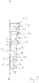
- Fig. 1 In the concrete embodiment of the Fig. 1 is an arrangement with a corresponding ultrasonic transducer 1 with two superposed electromechanical transducer elements 2, in particular with two piezo elements configured.
- the ultrasonic transducer 1 also has an attachment 4 with a surface 5 in contact with the medium. At this surface 5, the ultrasonic waves generated by the one or more electromechanical transducer elements 2 are delivered to the measuring medium.
- the in Fig. 1 shown essay 4 has a base 6, which is in contact, in particular in positive contact with the electromechanical transducer elements 2. Furthermore, the article 4 on a bending plate 7 on with the medium-contacting surface 5.
- the base 6 of the attachment 4 has an interface 16 to a damping element 15.
- This damping element 15 is formed as a cylindrical body with at least two mutually parallel annular grooves 10 and 12.
- the interface 16 may e.g. be designed as a welded joint.
- a first annular mass segment 9 is arranged, which has a greater wall thickness, in particular at least twice as thick a wall thickness as the annular groove 10.
- a second ring segment 11 is also arranged, which has a greater wall thickness, in particular at least twice as thick wall thickness, as the annular grooves 10 and 12th
- the damping element 15 is essentially defined by three radii. It is provided a first radius r 1 , which extends from a longitudinal axis L of the damping element 15 to an inner wall of the cylindrical body. Furthermore, a second radius r 2 is provided, which describes the distance of the outer wall in the region of the annular grooves 10, 12 to the longitudinal axis. Finally, a third radius r 3 is provided which describes the radial distance between the longitudinal axis and the outermost point of the second annular segment 11.
- the damping element 15 is connected via an interface 17 in the region of the third radius r 3 with a housing wall 14.
- the interface 17 may be formed as a welded joint.
- the interface is in Fig. 1 arranged on radially outside of the second radius r 2 and in the region of the third radius r 3 .
- the annular grooves 10 and 12 extend over a respective longitudinal section l 1 and l 2 along the longitudinal axis L. These longitudinal sections l 1 and l 2 are in Fig. 1 the same size.
- the second ring mass segment 11 extends over a longitudinal section l 3 , which in the embodiment of the Fig. 1 is greater than the lengths l 1 and l 2 .
- the first annular mass segment 9 is connected at its radially outermost point with a ring segment 8, which extends from the interface 16 to the ring mass 9.
- This ring segment 8 has a smaller, preferably at least twice as small wall thickness as the first annular mass segment 9.
- the Ringmassesegment 9 goes over at its radially innermost point in the annular groove. As a result, upon the application of an axial force, a deflection of this force through the annular mass segment takes place from outside to inside.
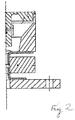
- Fig. 2 shows a damping element of the prior art of EP 1 340 964 B1 , The damping behavior of this damping element was investigated and with the damping behavior of the damping behavior of the arrangement of Fig. 1 compared.
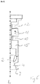
- Fig. 3 shows on the basis of the spectrum S1 with the solid line vibration spectra, the damping behavior of the arrangement of Fig. 1 in comparison with the spectrum S2 with the dashed line to the damping behavior of the arrangement of Fig. 2 ,
- a useful signal An which is needed to determine the level or the flow, is in the spectrum S1 at about 8200 Hz.
- the frequency range of the useful signal An for the arrangement of Fig. 1 be chosen in a very wide range.
- the frequency range of the useful signal can be selected arbitrarily in the range between 45,000 to about 120,000 Hz, without resulting in larger superimpositions of the useful signal An with the natural frequencies A-a1, A-a2, A-r1 of the damping element 15.
- the peaks in spectrum S1 at 28,000 and at 35,000 Hz represent axial vibrations, while the peak at about 136,000 Hz represents a rotational vibration.
- the spectrum of the damping element of the Fig. 2 true to scale implementation a whole series of natural oscillations, which overlap with a useful signal at about 82000 Hz.
- the peaks at 25000 and at 55000 Hz represent axial vibrations B-a1 and B-a2.
- the peaks at 71000 and 73000 Hz, on the other hand, represent rotational vibrations B-r1 and B-r2.
- Both the axial and the Rotational vibrations are in the in Fig. 3 variant shown below the useful frequency of 82000 Hz.
- Fig. 4 shows the vibration behavior of the damping element when transmitting and / or receiving an ultrasonic signal in the useful frequency range. It can be seen that predominantly the ultrasonic transducer 1, ie the electromechanical transducer elements 2 and 3 and the attachment 4 with the base 6 and the bending plate 7, are in vibration.
- the bending plate 7 has a radial deflection A1 during operation of the ultrasonic flow device. However, this deflection A1 is not transmitted to a subsequent damping structure, but the bending plate 7 is free-swinging and is not disturbed in its radial deflection by a damping structure. As a result, the radiated ultrasound signal is transmitted to the medium particularly well and unhindered.
- Fig. 5 shows the vibration behavior of the arrangement according to the invention in the illustrated embodiment according to Fig. 1 in the state of natural frequency A-a2 (axial mode at about 35000 Hz.).
- the annular mass segment 11 performs an axial movement between the two parallel annular grooves 10 and 12.
- the up and down movement of the ring gauge segment 11 results in a temporary deformation of the material wall in the region of the annular grooves 10 and 12 in the form of a temporary thinning or thickening.
- Fig. 6 shows the vibration behavior of the arrangement according to the invention in the illustrated embodiment according to Fig. 1 in the state of natural frequency A-r1 (rotation mode at about 137000 Hz.).
- the annular mass segment 11 performs a rotational movement between the two parallel annular grooves 10 and 12. Due to the oscillatory movement of the annular segment 11, there is a temporary material wall deformation in the region of the annular grooves 10 and 12 in the form of a wave-shaped bending of the material wall.
- Fig. 1 illustrated embodiment can be further modified within the scope of the invention.
- a prismatic basic structure is also possible, preferably with uniform prism surfaces.
- Individual segments of the basic structure, in particular also the annular mass segment 11, can be made polygonal in a two-dimensional section perpendicular to the longitudinal axis L.
- the damping element and the attachment are rotationally symmetrical and consist of metal.
- the attachment may preferably consist of stainless steel or titanium.
- the damping element is preferably made of stainless steel.
Landscapes
- Physics & Mathematics (AREA)
- Engineering & Computer Science (AREA)
- Acoustics & Sound (AREA)
- Multimedia (AREA)
- Measuring Volume Flow (AREA)
- Transducers For Ultrasonic Waves (AREA)
Claims (10)
- Dispositif comprenant un convertisseur à ultrasons (1) et un élément d'amortissement (15) avec un axe longitudinal (L), lequel élément d'amortissement (15) relie le convertisseur à ultrasons (1) avec une paroi de boîtier ou de tube de mesure (14), le convertisseur à ultrasons (1) comportant un bossage (4) avec une surface (5) en contact avec le produit, surface à partir de laquelle les signaux ultrasonores sont émis dans un produit gazeux ou liquide, et dispositif pour lequel l'élément d'amortissement (15) comporte au moins deux rainures annulaires (10, 12) et un segment de masse annulaire (11) disposé entre les rainures,
pour lequel
l'élément d'amortissement (15) présente une première fréquence propre (fa), à laquelle le segment de masse annulaire (11) exécute un mouvement axial parallèle à la direction longitudinale de l'élément d'amortissement (15),
cette première fréquence propre étant la fréquence propre maximale, dans le cas où plusieurs fréquences propres sont présentes, fréquence à laquelle le segment de masse annulaire (11) exécute un mouvement axial parallèle à la direction longitudinale de l'élément d'amortissement (15),
et
pour lequel l'élément d'amortissement (15) présente une deuxième fréquence propre (fr), à laquelle le segment de masse annulaire exécute un mouvement de rotation ;
cette deuxième fréquence propre étant la fréquence propre minimale, dans le cas où plusieurs fréquences propres sont présentes, fréquence à laquelle le segment de masse annulaire (11) exécute un mouvement de rotation,
caractérisé
en ce que le rapport entre la première fréquence propre (fa) et la deuxième fréquence propre (fr) est inférieur à 0,75,
et en ce que l'élément d'amortissement (15) présente, au moins dans la zone d'une première des au moins deux rainures annulaires (10), une première distance moyenne τ2 de la paroi extérieure d'une zone partielle cylindrique creuse à l'axe longitudinal (L),
l'élément d'amortissement (15) présentant au moins dans la zone d'une première des au moins deux rainures annulaires (10), une deuxième distance moyenne τ1 de la paroi intérieure de la zone partielle cylindrique creuse à l'axe longitudinal (L),
l'élément d'amortissement (15) présentant dans la zone du segment de masse annulaire (11), entre les rainures annulaires (10, 12), une longueur moyenne l3, dispositif pour lequel l'expression
- Dispositif selon la revendication 1, caractérisé en ce que le rapport entre la première fréquence propre (fa) et la deuxième fréquence propre (fr) est inférieur à 0,55, de préférence inférieur à 0,4.
- Dispositif selon la revendication 1 ou 2, pour lequel l'expression

- Dispositif selon l'une des revendications précédentes, caractérisé en ce que la zone partielle cylindrique creuse est à symétrie de révolution.
- Dispositif selon l'une des revendications précédentes, caractérisé en ce que le convertisseur à ultrasons (1) et l'élément d'amortissement (15) sont reliés par liaison de matière.
- Dispositif selon l'une des revendications précédentes, caractérisé en ce que l'élément d'amortissement (15) présente moins de cinq rainures annulaires (10, 12).
- Dispositif selon l'une des revendications précédentes, caractérisé en ce que les longueurs l1, l2 des au moins deux rainures annulaires (10, 12) sont identiques en direction axiale et en ce que la longueur l3 du segment de masse annulaire (11) est supérieure, de préférence au moins 1,5 fois supérieure à la longueur l1 ou l2 de l'une des deux rainures annulaires (10, 12).
- Dispositif selon l'une des revendications précédentes, caractérisé en ce que le convertisseur à ultrasons (1) comporte en son extrémité une plaque de flexion (7), laquelle présente la surface (5) à partir de laquelle le signal ultrasonore est émis dans le produit, laquelle plaque de flexion (7) est conçue de façon à pouvoir osciller librement sur les bords.
- Dispositif selon l'une des revendications précédentes, caractérisé en ce que la disposition dans une gamme de fréquence, dans laquelle le rapport entre la fréquence utile fn et la première fréquence propre fa est supérieur à 1,6 et dans laquelle le rapport de la fréquence utile fn et la deuxième fréquence fr est supérieur à 0,7, ne présente aucune fréquence propre axiale ou aucune fréquence propre de rotation.
- Appareil de terrain de la technique de mesure de process, notamment un débitmètre à ultrasons destiné à la mesure de produits gazeux, caractérisé en ce que l'appareil de terrain comprend un tube de mesure ou un récipient de stockage, sur lequel est monté un dispositif selon la revendication 1.
Applications Claiming Priority (2)
| Application Number | Priority Date | Filing Date | Title |
|---|---|---|---|
| DE102015103486.7A DE102015103486A1 (de) | 2015-03-10 | 2015-03-10 | Anordnung und Feldgerät der Prozessmesstechnik |
| PCT/EP2016/053092 WO2016142127A1 (fr) | 2015-03-10 | 2016-02-15 | Dispositif et appareil de terrain de la technique de mesure de processus |
Publications (2)
| Publication Number | Publication Date |
|---|---|
| EP3268954A1 EP3268954A1 (fr) | 2018-01-17 |
| EP3268954B1 true EP3268954B1 (fr) | 2018-11-28 |
Family
ID=55357989
Family Applications (1)
| Application Number | Title | Priority Date | Filing Date |
|---|---|---|---|
| EP16704442.9A Active EP3268954B1 (fr) | 2015-03-10 | 2016-02-15 | Dispositif et appareil de terrain de la technique de mesure de processus |
Country Status (5)
| Country | Link |
|---|---|
| US (1) | US10269336B2 (fr) |
| EP (1) | EP3268954B1 (fr) |
| CN (1) | CN107430845B (fr) |
| DE (1) | DE102015103486A1 (fr) |
| WO (1) | WO2016142127A1 (fr) |
Families Citing this family (2)
| Publication number | Priority date | Publication date | Assignee | Title |
|---|---|---|---|---|
| DE102015103486A1 (de) | 2015-03-10 | 2016-09-15 | Endress + Hauser Flowtec Ag | Anordnung und Feldgerät der Prozessmesstechnik |
| DE102015106352A1 (de) * | 2015-04-24 | 2016-10-27 | Endress + Hauser Flowtec Ag | Anordnung und Ultraschall-Durchflussmessgerät |
Family Cites Families (13)
| Publication number | Priority date | Publication date | Assignee | Title |
|---|---|---|---|---|
| DE50202211D1 (de) * | 2002-03-01 | 2005-03-17 | Sick Engineering Gmbh | Ultraschallwandleranordnung mit Ultraschallfilter |
| DE102004047786A1 (de) * | 2004-10-01 | 2006-04-06 | Robert Bosch Gmbh | Verfahren zur Pulsationskorrektur innerhalb eines einen Medienmassenstrom messenden Messgeräts |
| DK2073942T3 (en) * | 2006-09-28 | 2018-02-26 | 3L Ludvigsen As | Rotatable Ultrasonic Sealing Device |
| US8559269B2 (en) * | 2008-07-02 | 2013-10-15 | Chevron U.S.A., Inc. | Device and method for generating a beam of acoustic energy from a borehole, and applications thereof |
| DE102008033098C5 (de) * | 2008-07-15 | 2016-02-18 | Krohne Ag | Ultraschallwandler |
| US9504233B2 (en) * | 2009-03-06 | 2016-11-29 | Leah Stephens | Electromechanical horn for deterring animals |
| US8387443B2 (en) * | 2009-09-11 | 2013-03-05 | The Board Of Trustees Of The University Of Illinois | Microcantilever with reduced second harmonic while in contact with a surface and nano scale infrared spectrometer |
| DE102009046144A1 (de) * | 2009-10-29 | 2011-05-19 | Robert Bosch Gmbh | Ultraschallwandler zum Einsatz in einem fluiden Medium |
| EP2646171B1 (fr) * | 2010-12-03 | 2016-03-02 | Research Triangle Institute | Procédé de formation d'un transducteur ultrasonore, et appareil associé |
| DE102010064117A1 (de) * | 2010-12-23 | 2012-06-28 | Endress + Hauser Flowtec Ag | Ultraschallwandler |
| DE102011090082A1 (de) * | 2011-12-29 | 2013-07-04 | Endress + Hauser Flowtec Ag | Ultraschallwandler für ein Durchflussmessgerät |
| JP5919479B2 (ja) * | 2012-11-08 | 2016-05-18 | パナソニックIpマネジメント株式会社 | 超音波流量計 |
| DE102015103486A1 (de) | 2015-03-10 | 2016-09-15 | Endress + Hauser Flowtec Ag | Anordnung und Feldgerät der Prozessmesstechnik |
-
2015
- 2015-03-10 DE DE102015103486.7A patent/DE102015103486A1/de not_active Withdrawn
-
2016
- 2016-02-15 WO PCT/EP2016/053092 patent/WO2016142127A1/fr not_active Ceased
- 2016-02-15 CN CN201680014319.7A patent/CN107430845B/zh active Active
- 2016-02-15 EP EP16704442.9A patent/EP3268954B1/fr active Active
- 2016-02-15 US US15/555,714 patent/US10269336B2/en active Active
Non-Patent Citations (1)
| Title |
|---|
| None * |
Also Published As
| Publication number | Publication date |
|---|---|
| CN107430845B (zh) | 2021-04-13 |
| WO2016142127A1 (fr) | 2016-09-15 |
| EP3268954A1 (fr) | 2018-01-17 |
| US10269336B2 (en) | 2019-04-23 |
| DE102015103486A1 (de) | 2016-09-15 |
| CN107430845A (zh) | 2017-12-01 |
| US20180061390A1 (en) | 2018-03-01 |
Similar Documents
| Publication | Publication Date | Title |
|---|---|---|
| EP4105613B1 (fr) | Système de mesure permettant de mesurer au moins un paramètre d'un fluide | |
| EP3577427B1 (fr) | Compteur à ultrasons et procédé d'acquisition d'une grandeur de débit | |
| EP0903563B1 (fr) | Dispositif pour la détection et/ou la surveillance d'un niveau prédéterminé dans un récipient | |
| WO2009156250A1 (fr) | Procédé et système de mesure pour déterminer et/ou surveiller le débit d’un milieu à mesurer à travers un tube de mesure | |
| WO1994024524A1 (fr) | Indicateur de niveau | |
| WO2013097994A9 (fr) | Transducteur ultrasonore pour un débitmetre à ultrasons | |
| EP0684457A2 (fr) | Appareil pour la mesure du débit à ultrasons | |
| EP3486630B1 (fr) | Dispositif de mesure permettant de déterminer une pression dans un volume de mesure | |
| EP3244172B1 (fr) | Transducteur ultrasonique comprenant un élément rayonnant | |
| EP3855134B1 (fr) | Dispositif de mesure du débit d'écoulement d'un fluide | |
| EP3521774B1 (fr) | Dispositif de mesure d'écoulement à ultrasons et procédé de détermination de la vitesse d'écoulement | |
| EP3922972A2 (fr) | Dispositif de mesure de la pression d'un fluide circulant dans une tuyauterie | |
| DE102010064117A1 (de) | Ultraschallwandler | |
| EP3631378B1 (fr) | Capteur de mesure pour mesurer le débit massique d'un milieu fluide | |
| EP1378727A1 (fr) | Débitmètre à ultrasons | |
| EP3246668B1 (fr) | Dispositif de mesure et procede de determination de la vitesse d'ecoulement d'un fluide s'ecoulant dans une conduite | |
| EP3273205A1 (fr) | Procede et systeme de debitmetre a ultrasons a pince et corps destine a realiser la mesure | |
| DE102010064119A1 (de) | Durchflussmessgerät | |
| EP3268954B1 (fr) | Dispositif et appareil de terrain de la technique de mesure de processus | |
| EP3894799B1 (fr) | Agencement de transducteurs ultrasonores d'un appareil de mesure de debit a ultrasons a pinces, et appareil de mesure de debit a ultrasons a pinces et procede de mise en marche de l'appareil de mesure de debit a ultrasons a pinces | |
| DE102009039633A1 (de) | Ultraschall-Durchflussmesser | |
| DE202020104105U1 (de) | Durchflussmessgerät zur Messung des Durchflusses eines Fluids | |
| DE202013105800U1 (de) | Ultraschallmessvorrichtung zum Bestimmen der Strömungsgeschwindigkeit | |
| EP3286528B1 (fr) | Disposition et débitmètre ultrasonique | |
| DE102020126021A1 (de) | Fluidmesseinrichtung |
Legal Events
| Date | Code | Title | Description |
|---|---|---|---|
| STAA | Information on the status of an ep patent application or granted ep patent |
Free format text: STATUS: THE INTERNATIONAL PUBLICATION HAS BEEN MADE |
|
| PUAI | Public reference made under article 153(3) epc to a published international application that has entered the european phase |
Free format text: ORIGINAL CODE: 0009012 |
|
| STAA | Information on the status of an ep patent application or granted ep patent |
Free format text: STATUS: REQUEST FOR EXAMINATION WAS MADE |
|
| 17P | Request for examination filed |
Effective date: 20170824 |
|
| AK | Designated contracting states |
Kind code of ref document: A1 Designated state(s): AL AT BE BG CH CY CZ DE DK EE ES FI FR GB GR HR HU IE IS IT LI LT LU LV MC MK MT NL NO PL PT RO RS SE SI SK SM TR |
|
| AX | Request for extension of the european patent |
Extension state: BA ME |
|
| DAV | Request for validation of the european patent (deleted) | ||
| DAX | Request for extension of the european patent (deleted) | ||
| GRAP | Despatch of communication of intention to grant a patent |
Free format text: ORIGINAL CODE: EPIDOSNIGR1 |
|
| STAA | Information on the status of an ep patent application or granted ep patent |
Free format text: STATUS: GRANT OF PATENT IS INTENDED |
|
| INTG | Intention to grant announced |
Effective date: 20180712 |
|
| GRAS | Grant fee paid |
Free format text: ORIGINAL CODE: EPIDOSNIGR3 |
|
| GRAA | (expected) grant |
Free format text: ORIGINAL CODE: 0009210 |
|
| STAA | Information on the status of an ep patent application or granted ep patent |
Free format text: STATUS: THE PATENT HAS BEEN GRANTED |
|
| AK | Designated contracting states |
Kind code of ref document: B1 Designated state(s): AL AT BE BG CH CY CZ DE DK EE ES FI FR GB GR HR HU IE IS IT LI LT LU LV MC MK MT NL NO PL PT RO RS SE SI SK SM TR |
|
| REG | Reference to a national code |
Ref country code: CH Ref legal event code: EP |
|
| REG | Reference to a national code |
Ref country code: AT Ref legal event code: REF Ref document number: 1071148 Country of ref document: AT Kind code of ref document: T Effective date: 20181215 |
|
| REG | Reference to a national code |
Ref country code: DE Ref legal event code: R096 Ref document number: 502016002639 Country of ref document: DE |
|
| REG | Reference to a national code |
Ref country code: IE Ref legal event code: FG4D Free format text: LANGUAGE OF EP DOCUMENT: GERMAN |
|
| REG | Reference to a national code |
Ref country code: NL Ref legal event code: MP Effective date: 20181128 |
|
| REG | Reference to a national code |
Ref country code: LT Ref legal event code: MG4D |
|
| PG25 | Lapsed in a contracting state [announced via postgrant information from national office to epo] |
Ref country code: FI Free format text: LAPSE BECAUSE OF FAILURE TO SUBMIT A TRANSLATION OF THE DESCRIPTION OR TO PAY THE FEE WITHIN THE PRESCRIBED TIME-LIMIT Effective date: 20181128 Ref country code: IS Free format text: LAPSE BECAUSE OF FAILURE TO SUBMIT A TRANSLATION OF THE DESCRIPTION OR TO PAY THE FEE WITHIN THE PRESCRIBED TIME-LIMIT Effective date: 20190328 Ref country code: NO Free format text: LAPSE BECAUSE OF FAILURE TO SUBMIT A TRANSLATION OF THE DESCRIPTION OR TO PAY THE FEE WITHIN THE PRESCRIBED TIME-LIMIT Effective date: 20190228 Ref country code: HR Free format text: LAPSE BECAUSE OF FAILURE TO SUBMIT A TRANSLATION OF THE DESCRIPTION OR TO PAY THE FEE WITHIN THE PRESCRIBED TIME-LIMIT Effective date: 20181128 Ref country code: BG Free format text: LAPSE BECAUSE OF FAILURE TO SUBMIT A TRANSLATION OF THE DESCRIPTION OR TO PAY THE FEE WITHIN THE PRESCRIBED TIME-LIMIT Effective date: 20190228 Ref country code: LT Free format text: LAPSE BECAUSE OF FAILURE TO SUBMIT A TRANSLATION OF THE DESCRIPTION OR TO PAY THE FEE WITHIN THE PRESCRIBED TIME-LIMIT Effective date: 20181128 Ref country code: ES Free format text: LAPSE BECAUSE OF FAILURE TO SUBMIT A TRANSLATION OF THE DESCRIPTION OR TO PAY THE FEE WITHIN THE PRESCRIBED TIME-LIMIT Effective date: 20181128 Ref country code: LV Free format text: LAPSE BECAUSE OF FAILURE TO SUBMIT A TRANSLATION OF THE DESCRIPTION OR TO PAY THE FEE WITHIN THE PRESCRIBED TIME-LIMIT Effective date: 20181128 |
|
| PG25 | Lapsed in a contracting state [announced via postgrant information from national office to epo] |
Ref country code: GR Free format text: LAPSE BECAUSE OF FAILURE TO SUBMIT A TRANSLATION OF THE DESCRIPTION OR TO PAY THE FEE WITHIN THE PRESCRIBED TIME-LIMIT Effective date: 20190301 Ref country code: PT Free format text: LAPSE BECAUSE OF FAILURE TO SUBMIT A TRANSLATION OF THE DESCRIPTION OR TO PAY THE FEE WITHIN THE PRESCRIBED TIME-LIMIT Effective date: 20190328 Ref country code: AL Free format text: LAPSE BECAUSE OF FAILURE TO SUBMIT A TRANSLATION OF THE DESCRIPTION OR TO PAY THE FEE WITHIN THE PRESCRIBED TIME-LIMIT Effective date: 20181128 Ref country code: RS Free format text: LAPSE BECAUSE OF FAILURE TO SUBMIT A TRANSLATION OF THE DESCRIPTION OR TO PAY THE FEE WITHIN THE PRESCRIBED TIME-LIMIT Effective date: 20181128 Ref country code: SE Free format text: LAPSE BECAUSE OF FAILURE TO SUBMIT A TRANSLATION OF THE DESCRIPTION OR TO PAY THE FEE WITHIN THE PRESCRIBED TIME-LIMIT Effective date: 20181128 |
|
| PG25 | Lapsed in a contracting state [announced via postgrant information from national office to epo] |
Ref country code: NL Free format text: LAPSE BECAUSE OF FAILURE TO SUBMIT A TRANSLATION OF THE DESCRIPTION OR TO PAY THE FEE WITHIN THE PRESCRIBED TIME-LIMIT Effective date: 20181128 |
|
| PG25 | Lapsed in a contracting state [announced via postgrant information from national office to epo] |
Ref country code: DK Free format text: LAPSE BECAUSE OF FAILURE TO SUBMIT A TRANSLATION OF THE DESCRIPTION OR TO PAY THE FEE WITHIN THE PRESCRIBED TIME-LIMIT Effective date: 20181128 Ref country code: PL Free format text: LAPSE BECAUSE OF FAILURE TO SUBMIT A TRANSLATION OF THE DESCRIPTION OR TO PAY THE FEE WITHIN THE PRESCRIBED TIME-LIMIT Effective date: 20181128 Ref country code: CZ Free format text: LAPSE BECAUSE OF FAILURE TO SUBMIT A TRANSLATION OF THE DESCRIPTION OR TO PAY THE FEE WITHIN THE PRESCRIBED TIME-LIMIT Effective date: 20181128 |
|
| REG | Reference to a national code |
Ref country code: DE Ref legal event code: R097 Ref document number: 502016002639 Country of ref document: DE |
|
| PG25 | Lapsed in a contracting state [announced via postgrant information from national office to epo] |
Ref country code: RO Free format text: LAPSE BECAUSE OF FAILURE TO SUBMIT A TRANSLATION OF THE DESCRIPTION OR TO PAY THE FEE WITHIN THE PRESCRIBED TIME-LIMIT Effective date: 20181128 Ref country code: SK Free format text: LAPSE BECAUSE OF FAILURE TO SUBMIT A TRANSLATION OF THE DESCRIPTION OR TO PAY THE FEE WITHIN THE PRESCRIBED TIME-LIMIT Effective date: 20181128 Ref country code: SM Free format text: LAPSE BECAUSE OF FAILURE TO SUBMIT A TRANSLATION OF THE DESCRIPTION OR TO PAY THE FEE WITHIN THE PRESCRIBED TIME-LIMIT Effective date: 20181128 Ref country code: EE Free format text: LAPSE BECAUSE OF FAILURE TO SUBMIT A TRANSLATION OF THE DESCRIPTION OR TO PAY THE FEE WITHIN THE PRESCRIBED TIME-LIMIT Effective date: 20181128 |
|
| REG | Reference to a national code |
Ref country code: CH Ref legal event code: PL |
|
| PLBE | No opposition filed within time limit |
Free format text: ORIGINAL CODE: 0009261 |
|
| STAA | Information on the status of an ep patent application or granted ep patent |
Free format text: STATUS: NO OPPOSITION FILED WITHIN TIME LIMIT |
|
| PG25 | Lapsed in a contracting state [announced via postgrant information from national office to epo] |
Ref country code: LU Free format text: LAPSE BECAUSE OF NON-PAYMENT OF DUE FEES Effective date: 20190215 Ref country code: MC Free format text: LAPSE BECAUSE OF FAILURE TO SUBMIT A TRANSLATION OF THE DESCRIPTION OR TO PAY THE FEE WITHIN THE PRESCRIBED TIME-LIMIT Effective date: 20181128 |
|
| 26N | No opposition filed |
Effective date: 20190829 |
|
| REG | Reference to a national code |
Ref country code: BE Ref legal event code: MM Effective date: 20190228 |
|
| REG | Reference to a national code |
Ref country code: IE Ref legal event code: MM4A |
|
| PG25 | Lapsed in a contracting state [announced via postgrant information from national office to epo] |
Ref country code: LI Free format text: LAPSE BECAUSE OF NON-PAYMENT OF DUE FEES Effective date: 20190228 Ref country code: CH Free format text: LAPSE BECAUSE OF NON-PAYMENT OF DUE FEES Effective date: 20190228 |
|
| PG25 | Lapsed in a contracting state [announced via postgrant information from national office to epo] |
Ref country code: IE Free format text: LAPSE BECAUSE OF NON-PAYMENT OF DUE FEES Effective date: 20190215 |
|
| PG25 | Lapsed in a contracting state [announced via postgrant information from national office to epo] |
Ref country code: BE Free format text: LAPSE BECAUSE OF NON-PAYMENT OF DUE FEES Effective date: 20190228 |
|
| PG25 | Lapsed in a contracting state [announced via postgrant information from national office to epo] |
Ref country code: TR Free format text: LAPSE BECAUSE OF FAILURE TO SUBMIT A TRANSLATION OF THE DESCRIPTION OR TO PAY THE FEE WITHIN THE PRESCRIBED TIME-LIMIT Effective date: 20181128 |
|
| PG25 | Lapsed in a contracting state [announced via postgrant information from national office to epo] |
Ref country code: MT Free format text: LAPSE BECAUSE OF FAILURE TO SUBMIT A TRANSLATION OF THE DESCRIPTION OR TO PAY THE FEE WITHIN THE PRESCRIBED TIME-LIMIT Effective date: 20181128 |
|
| PG25 | Lapsed in a contracting state [announced via postgrant information from national office to epo] |
Ref country code: CY Free format text: LAPSE BECAUSE OF FAILURE TO SUBMIT A TRANSLATION OF THE DESCRIPTION OR TO PAY THE FEE WITHIN THE PRESCRIBED TIME-LIMIT Effective date: 20181128 |
|
| PG25 | Lapsed in a contracting state [announced via postgrant information from national office to epo] |
Ref country code: HU Free format text: LAPSE BECAUSE OF FAILURE TO SUBMIT A TRANSLATION OF THE DESCRIPTION OR TO PAY THE FEE WITHIN THE PRESCRIBED TIME-LIMIT; INVALID AB INITIO Effective date: 20160215 |
|
| PG25 | Lapsed in a contracting state [announced via postgrant information from national office to epo] |
Ref country code: SI Free format text: LAPSE BECAUSE OF FAILURE TO SUBMIT A TRANSLATION OF THE DESCRIPTION OR TO PAY THE FEE WITHIN THE PRESCRIBED TIME-LIMIT Effective date: 20181128 |
|
| REG | Reference to a national code |
Ref country code: AT Ref legal event code: MM01 Ref document number: 1071148 Country of ref document: AT Kind code of ref document: T Effective date: 20210215 |
|
| PG25 | Lapsed in a contracting state [announced via postgrant information from national office to epo] |
Ref country code: AT Free format text: LAPSE BECAUSE OF NON-PAYMENT OF DUE FEES Effective date: 20210215 |
|
| PG25 | Lapsed in a contracting state [announced via postgrant information from national office to epo] |
Ref country code: MK Free format text: LAPSE BECAUSE OF FAILURE TO SUBMIT A TRANSLATION OF THE DESCRIPTION OR TO PAY THE FEE WITHIN THE PRESCRIBED TIME-LIMIT Effective date: 20181128 |
|
| P01 | Opt-out of the competence of the unified patent court (upc) registered |
Effective date: 20230601 |
|
| PGFP | Annual fee paid to national office [announced via postgrant information from national office to epo] |
Ref country code: GB Payment date: 20260219 Year of fee payment: 11 |
|
| PGFP | Annual fee paid to national office [announced via postgrant information from national office to epo] |
Ref country code: DE Payment date: 20260218 Year of fee payment: 11 |
|
| PGFP | Annual fee paid to national office [announced via postgrant information from national office to epo] |
Ref country code: IT Payment date: 20260224 Year of fee payment: 11 |
|
| PGFP | Annual fee paid to national office [announced via postgrant information from national office to epo] |
Ref country code: FR Payment date: 20260218 Year of fee payment: 11 |