EP3269603A1 - Regensensor und wischeransteuerungsvorrichtung damit - Google Patents
Regensensor und wischeransteuerungsvorrichtung damit Download PDFInfo
- Publication number
- EP3269603A1 EP3269603A1 EP16761941.0A EP16761941A EP3269603A1 EP 3269603 A1 EP3269603 A1 EP 3269603A1 EP 16761941 A EP16761941 A EP 16761941A EP 3269603 A1 EP3269603 A1 EP 3269603A1
- Authority
- EP
- European Patent Office
- Prior art keywords
- substrate
- reaction layer
- sensing
- sensing electrode
- wiper
- Prior art date
- Legal status (The legal status is an assumption and is not a legal conclusion. Google has not performed a legal analysis and makes no representation as to the accuracy of the status listed.)
- Granted
Links
Images



Classifications
-
- B—PERFORMING OPERATIONS; TRANSPORTING
- B60—VEHICLES IN GENERAL
- B60S—SERVICING, CLEANING, REPAIRING, SUPPORTING, LIFTING, OR MANOEUVRING OF VEHICLES, NOT OTHERWISE PROVIDED FOR
- B60S1/00—Cleaning of vehicles
- B60S1/02—Cleaning windscreens, windows or optical devices
- B60S1/04—Wipers or the like, e.g. scrapers
- B60S1/06—Wipers or the like, e.g. scrapers characterised by the drive
- B60S1/08—Wipers or the like, e.g. scrapers characterised by the drive electrically driven
- B60S1/0818—Wipers or the like, e.g. scrapers characterised by the drive electrically driven including control systems responsive to external conditions, e.g. by detection of moisture, dirt or the like
- B60S1/0822—Wipers or the like, e.g. scrapers characterised by the drive electrically driven including control systems responsive to external conditions, e.g. by detection of moisture, dirt or the like characterized by the arrangement or type of detection means
- B60S1/0825—Capacitive rain sensor
-
- B—PERFORMING OPERATIONS; TRANSPORTING
- B60—VEHICLES IN GENERAL
- B60S—SERVICING, CLEANING, REPAIRING, SUPPORTING, LIFTING, OR MANOEUVRING OF VEHICLES, NOT OTHERWISE PROVIDED FOR
- B60S1/00—Cleaning of vehicles
- B60S1/02—Cleaning windscreens, windows or optical devices
- B60S1/04—Wipers or the like, e.g. scrapers
- B60S1/06—Wipers or the like, e.g. scrapers characterised by the drive
- B60S1/08—Wipers or the like, e.g. scrapers characterised by the drive electrically driven
- B60S1/0818—Wipers or the like, e.g. scrapers characterised by the drive electrically driven including control systems responsive to external conditions, e.g. by detection of moisture, dirt or the like
- B60S1/0822—Wipers or the like, e.g. scrapers characterised by the drive electrically driven including control systems responsive to external conditions, e.g. by detection of moisture, dirt or the like characterized by the arrangement or type of detection means
- B60S1/0851—Resistive rain sensor
-
- B—PERFORMING OPERATIONS; TRANSPORTING
- B60—VEHICLES IN GENERAL
- B60S—SERVICING, CLEANING, REPAIRING, SUPPORTING, LIFTING, OR MANOEUVRING OF VEHICLES, NOT OTHERWISE PROVIDED FOR
- B60S1/00—Cleaning of vehicles
- B60S1/02—Cleaning windscreens, windows or optical devices
- B60S1/04—Wipers or the like, e.g. scrapers
- B60S1/06—Wipers or the like, e.g. scrapers characterised by the drive
- B60S1/08—Wipers or the like, e.g. scrapers characterised by the drive electrically driven
- B60S1/0818—Wipers or the like, e.g. scrapers characterised by the drive electrically driven including control systems responsive to external conditions, e.g. by detection of moisture, dirt or the like
- B60S1/0822—Wipers or the like, e.g. scrapers characterised by the drive electrically driven including control systems responsive to external conditions, e.g. by detection of moisture, dirt or the like characterized by the arrangement or type of detection means
-
- B—PERFORMING OPERATIONS; TRANSPORTING
- B60—VEHICLES IN GENERAL
- B60S—SERVICING, CLEANING, REPAIRING, SUPPORTING, LIFTING, OR MANOEUVRING OF VEHICLES, NOT OTHERWISE PROVIDED FOR
- B60S1/00—Cleaning of vehicles
- B60S1/02—Cleaning windscreens, windows or optical devices
- B60S1/04—Wipers or the like, e.g. scrapers
- B60S1/06—Wipers or the like, e.g. scrapers characterised by the drive
- B60S1/08—Wipers or the like, e.g. scrapers characterised by the drive electrically driven
-
- G—PHYSICS
- G01—MEASURING; TESTING
- G01N—INVESTIGATING OR ANALYSING MATERIALS BY DETERMINING THEIR CHEMICAL OR PHYSICAL PROPERTIES
- G01N27/00—Investigating or analysing materials by the use of electric, electrochemical, or magnetic means
- G01N27/02—Investigating or analysing materials by the use of electric, electrochemical, or magnetic means by investigating impedance
- G01N27/04—Investigating or analysing materials by the use of electric, electrochemical, or magnetic means by investigating impedance by investigating resistance
- G01N27/06—Investigating or analysing materials by the use of electric, electrochemical, or magnetic means by investigating impedance by investigating resistance of a liquid
-
- G—PHYSICS
- G01—MEASURING; TESTING
- G01N—INVESTIGATING OR ANALYSING MATERIALS BY DETERMINING THEIR CHEMICAL OR PHYSICAL PROPERTIES
- G01N27/00—Investigating or analysing materials by the use of electric, electrochemical, or magnetic means
- G01N27/02—Investigating or analysing materials by the use of electric, electrochemical, or magnetic means by investigating impedance
- G01N27/22—Investigating or analysing materials by the use of electric, electrochemical, or magnetic means by investigating impedance by investigating capacitance
- G01N27/223—Investigating or analysing materials by the use of electric, electrochemical, or magnetic means by investigating impedance by investigating capacitance for determining moisture content, e.g. humidity
-
- G—PHYSICS
- G01—MEASURING; TESTING
- G01W—METEOROLOGY
- G01W1/00—Meteorology
- G01W1/14—Rainfall or precipitation gauges
Definitions
- An embodiment relates to a rain sensor, and more particularly, to a rain sensor capable of determining presence of rainfall and a rainfall amount based on impedance variation amount and driving a wiper based on a rainfall amount and a wiper driving apparatus comprising the same.
- a wiper is installed on the windshield of a vehicle in order to overcome a visibility obstacle caused by rainwater in a rainfall.
- These wipers control an intermittent speed thereof step by step depending on a dropping degree of rainwater.
- a speed control system of the wiper is controlled by only a few steps, the wiper may not be operated at a speed a driver desires depending on an amount of rainwater.
- a circuit board on which a light source and a sensor which is a light receiving element are mounted is inclined with respect to a windshield surface, so that a rain sensing efficiency can be increased by receiving only an optical signal reflected from raindrops themselves while minimizing an influence of light reflected from the windshield surface. That is, light directly reflected from the windshield goes outside a light receiving range of the light receiving element and is reflected on the windshield to minimize an amount of light received by the light receiving element.
- the circuit board having the light source and the light receiving element is disposed at an angle to the windshield surface so as to detect only an irregular reflection signal from the raindrops.
- the light emitted from the light source may be directly absorbed by the light receiving element, and thus the rain sensing efficiency is somewhat incomplete and insufficient. That is, the light emitted from the light source spreads over a range of angles, and even if the light source and the light receiving element are arranged so as to be inclined with respect to the windshield surface, a part of the light is directly emitted toward the light receiving element other than the light coming out of the windshield. Thus, there is a problem of somewhat lowering the raindrop detection efficiency due to interference light absorbed by the light receiving element from the light source.
- a rain sensor which detects a change in impedance caused by raindrops falling on a windshield of a vehicle and determines presence of rainfall and a rainfall amount, and a wiper driving apparatus including the same.
- a rain sensor which may determine presence of rainfall and a rainfall amount using a carbon micro-coil device and accordingly capable of controlling a driving condition of the wiper and a driving speed of the wiper, and a wiper driving apparatus including the same.
- a rain sensor comprises: a substrate; a sensing electrode formed on a first surface of the substrate; a reaction layer formed on the first surface of the substrate and burying an upper surface of the substrate and the sensing electrode; a driving unit electrically connected to the sensing electrode formed on the first surface of the substrate and processing a sensing signal transmitted through the sensing electrode; and a protective layer formed surrounding the driving unit, wherein an impedance value according to a change of at least one of a force and a dielectric constant caused by presence of rainfall is changed and the sensing electrode transmits the sensing signal with respect to a variation amount of the impedance value of the reaction layer to the driving unit.
- reaction layer includes a carbon micro-coil material.
- reaction layer includes a carbon micro-coil material, a resin, and a dispersant.
- reaction layer is disposed on the substrate on which the sensing electrode having a predetermined thickness is formed.
- each of the plurality of sensing electrodes includes a first electrode part disposed in an edge region of the substrate and a second electrode part extending in a longitudinal direction of the substrate from one end of the first electrode part, and the internal angle between the first electrode and the second electrode parts is an obtuse angle.
- the rain sensor further includes a via formed through the substrate, wherein one end of the via is connected to the sensing electrode, and the other end is connected to the driving unit.
- reaction layer causes a change in an imaginary part of a positive of impedance due to a force applied by the occurrence of the rainfall and a change in a negative imaginary part of impedance due to a change in a dielectric constant caused by an object existing on the second surface.
- a wiper driving apparatus includes: a windshield; a sensor unit attached to a first surface of the windshield and having impedance value changed by an object contacting a second surface of the windshield; and a control unit for receiving a sensing signal corresponding to a variation amount of the impedance value through the sensor unit, determining presence of rainfall based on the received sensing signal, and driving a wiper depending on the determined presence of rainfall.
- the sensor unit includes a substrate, a sensing electrode formed on a first surface of the substrate, a reaction layer formed on the first surface of the substrate and burying an upper surface of the substrate and the sensing electrode, a driving unit electrically connected to the sensing electrode formed on the first surface of the substrate and processing a sensing signal transmitted through the sensing electrode, and a protective layer formed surrounding the driving unit, wherein an impedance value of the reaction layer is changed by the contact object, and the sensing electrode transmits the sensing signal with respect to the impedance value of the reaction layer to the driving unit.
- reaction layer includes a carbon micro-coil material.
- reaction layer includes a carbon micro-coil material, a resin, and a dispersant.
- reaction layer is disposed on the substrate on which the sensing electrode having a predetermined thickness is formed.
- each of the plurality of sensing electrodes includes a first electrode part disposed in an edge region of the substrate and a second electrode part extending in a longitudinal direction of the substrate from one end of the first electrode part, and the internal angle between the first electrode and the second electrode parts is an obtuse angle.
- the sensor unit further includes a via formed through the substrate, wherein one end of the via is connected to the sensing electrode, and the other end is connected to the driving unit.
- the sensor unit detects presence of rainfall and a rainfall amount based on a change of a positive imaginary part of impedance due to a force applied to the second surface of the windshield by the contact object and a change of a negative imaginary part of impedance due to a change of a dielectric constant by an object existing on the second surface.
- the sensor unit further includes an adhesive member disposed between the first surface of the windshield and the rain sensor unit.
- control unit sets whether the wiper is driven or not and the driving speed based on a variation amount of the impedance value.
- a wiper when a rainfall occurs, by instantly reacting to the rainfall, a wiper is driven under driving conditions depending on an amount of rainfall, thereby improving convenience of a driver in case of rainy weather.
- presence of rainfall and a rainfall amount are determined using the carbon micro-coil device, thereby providing a rain sensor having differentiated characteristics such as response characteristics, precision, accuracy, power consumption, miniaturization, and the like in comparison with a conventional optical system.
- Combinations of blocks and steps of flowcharts in the accompanying drawings can be performed by computer program instructions.
- Such computer program instructions can be embedded in a processor of a general-purpose computer, a special-purpose computer, or other programmable data processing equipment. Therefore, the instructions performed by the processor of a computer or other programmable data processing equipment generate means for performing functions described in each of the blocks or each of the steps in the flowcharts in the drawings.
- the computer program instructions can also be saved in a computer-usable or computer-readable memory capable of supporting a computer or other programmable data processing equipment to implement a function in a specific way, the instructions stored in the computer-usable or computer-readable memory can also produce a manufacturing item which incorporates an instruction means performing a function described in each of the blocks or each of the steps of the flowcharts in the drawings.
- the computer program instructions can also be embedded in a computer or other programmable data processing equipment
- the instructions performed in a computer or other programmable data processing equipment by a process executed in a computer being generated by a series of operation steps being performed in the computer or other programmable data processing equipment can also provide steps for executing functions described in each of the blocks and each of the steps of the flowcharts in the drawings.
- Each of the blocks or each of the steps may represent a module, a segment, or a part of a code including one or more executable instructions for executing a specified logical function(s). Also, it should be noted that functions mentioned in the blocks or steps can also be performed in a different order in a few alternative embodiments. For example, two blocks or steps which are consecutively illustrated can substantially be performed simultaneously, or the blocks or steps can also be performed in a reverse order sometimes according to corresponding functions.
- FIG. 1 is a side view illustrating a state where a rain sensor is mounted on a windshield of a vehicle according to an embodiment of the present invention
- FIG. 2 is a sectional view illustrating the detailed structure of the rain sensor shown in FIG. 1
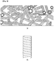
- FIG. 3 is a view illustrating a reaction layer shown in FIG. 2
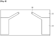
- FIG. 4 is a plan view of a sensing electrode shown in FIG. 2 .
- a rain sensor 20 is mounted on a windshield 10 of a vehicle.
- the rain sensor 20 is installed so as to face the windshield 10 of the vehicle and detects a change in impedance depending on whether there are raindrops falling on the windshield 10 or an amount of the raindrops.
- the rain sensor 20 forms a sensing region at a predetermined position of the windshield 10 of the vehicle and senses information depending on the state of raindrops generated in the sensing region.
- the rain sensor 20 includes a substrate 21, a sensing electrode 22, a reaction layer 23, a driving unit 24, and a protective layer 25.
- the rain sensor 20 detects a change in impedance depending on a presence or absence of raindrops falling on the windshield 10 in a certain area inside the windshield 10 of the vehicle, and provides information for driving wipers.
- the substrate 21 is a base substrate on which the sensing electrode 22, the reaction layer 23, and the driving unit 24 are mounted.
- the sensing electrode 22 is formed on the substrate 21.
- the sensing electrode 22 is formed on an upper surface of the substrate 21 while being buried by the reaction layer 23.
- the sensing electrode 22 may be formed in plural number.
- the sensing electrode 22 senses a change in impedance as a reaction of the reaction layer 23 occurs due to a material formed on a surface of the reaction layer 23.
- the sensing electrode 22 may include a first sensing electrode having a positive polarity and a second sensing electrode having a negative polarity.
- the reaction layer 23 is formed on the substrate 21 and is formed by burying the upper surface of the substrate 21 and the sensing electrode 22.
- the reaction layer 23 is formed on the substrate 21 on which the sensing electrode 22 having a predetermined thickness is formed.
- the reaction layer 23 is formed of a conductive material and has a property in which the impedance varies depending on a change in a force or a dielectric constant generated by an external material.
- the reaction layer 23 is a carbon micro-coil (CMC) having a spring shape. That is, the reaction layer 23 is formed by depositing at least one of hydrocarbons such as acetylene, methane, propane, and benzene on the substrate 21 by a chemical vapor deposition (CVD) process.
- CMC carbon micro-coil
- CVD chemical vapor deposition
- reaction layer 23 may be formed using a metal catalyst on the basis of nickel or nickel-iron.
- the CMC as shown in FIG. 3 may have a shape which is not straight, but is curled like a pig tail and is amorphous carbon fiber with a unique structure a fiber material may not have. Further, the CMC has a superelasticity which extends to a length, which is ten times or more that of an original coil.
- FIG. 3 illustrates a coil formed in the reaction layer 23, and (b) of FIG. 3 is a detailed view of the coil.
- Morphology of the reaction layer 23 has a 3D-helical/spiral structure, and the crystal structure is amorphous.
- the reaction layer 23 as described above is formed by growing carbon fibers into a coil shape, and accordingly, the reaction layer 23 has a cross-sectional structure in which carbon fibers are grown in a coil shape.
- a change in impedance of the reaction layer 23 occurs due to a force applied by a contact of a specific material to the surface of the windshield 10 to which the rain sensor 20 is attached or a dielectric constant of the specific material.
- the sensing electrode 22 senses a change in impedance of the reaction layer 23, thereby transmitting a sensing signal corresponding to the change in impedance to the driving unit 24.
- the driving unit 24 is formed on a lower surface of the substrate 21. Accordingly, the driving unit 24 detects presence of rainfall and a rainfall amount depending on a sensing signal transmitted through the sensing electrode 22, and generates a control signal for controlling an operation of the wiper depending on the detected presence of rainfall and rainfall amount.
- REAL TERM of impedance is resistance
- POSITIVE IMAGINARY TERM is inductance
- NEGATIVE IMAGINARY TERM is capacitance
- the impedance consists of a summation of the resistance, inductance and capacitance.
- the rain sensor 20 like a general resistor, an inductor, and a capacitor, also needs a pair of sensing electrodes 22 so as to detect a change in impedance generated in the reaction layer 23.
- the sensing electrode 22 functions to connect the reaction layer 23 and the driving unit 24 while optimizing the sensing characteristics of the reaction layer 23.
- the sensed impedance value is a summation of the resistance value, the inductance value, and the capacitance value, and the impedance value is linearly decreased depending on a degree of the force or dielectric constant applied to the surface.
- the sensing electrode 22 has a structure as shown in FIG. 4 and is formed on the substrate 21.
- the sensing electrode 22 includes a first electrode part formed on an edge region of the substrate 21 and a second electrode part extending from one end of the first electrode part to a central region of the substrate and having a predetermined inclination angle with respect to the one end of the first electrode part.
- a state of change in impedance generated in the reaction layer 23 varies depending on the shape of the sensing electrode 22.
- the sensing electrode 22 including the first electrode part and the second electrode part is formed on the substrate 21.
- a via 26 is formed at a lower portion of one end of the second electrode part.
- the via 26 is formed by burying a through hole passing through the upper and lower surfaces of the substrate 21 with a metal material.
- One end of the via 26 is connected to the sensing electrode 22 by passing through the substrate 21, and the other end of the via 26 is connected to the driving unit 24 attached to the lower surface of the substrate 21.
- the driving unit 24 is provided with an analog front end (AFE) and is connected to the sensing electrode 22 through the via 26.
- AFE analog front end
- the AFE performs a differential amplification function, and there is a difference in the state of change of the impedance according to the generation of the rainfall depending on whether the differential amplification is positive or negative.
- the driving unit 24 senses a state of change of the impedance value based on a reference value according to the differential amplification state, and when a degree of the state of change deviates from a critical value, the wiper is driven to remove raindrops.
- impedance variation occurs in the reaction layer 23 depending on the change in the applied force or the dielectric constant.
- the variation amount of the impedance may correspond to the presence of rainfall and rainfall amount. That is, the force or the dielectric constant applied to the reaction layer 23 is increased in proportion to the rainfall amount, and the impedance variation amount is decreased in inverse proportion to the increase of the dielectric constant or the force.
- a differential signal depending on the differential amplification of the AFE of the driving unit 24 is output depending on the amplitude change of the internal clock.
- the output differential signal is converted into a digital signal and transmitted to a main control unit (to be described later) of the vehicle.
- the main control unit (not shown) detects the presence of rainfall and the rainfall amount based on an impedance variation amount depending on the digital signal transmitted. When the rainfall occurs and the rainfall amount exceeds a critical point, the wiper is operated to remove raindrops.
- FIG. 5 is a view for explaining a method of manufacturing the rain sensor 20 shown in FIG. 2 .
- a solution 81 for forming the reaction layer 23 is first prepared in a plating tank 80.
- the solution 81 may be made of a carbon micro-coil material (CMC material). At this point, the solution 81 may include only the carbon micro-coil material, and otherwise, resin and dispersant may be further added.
- CMC material carbon micro-coil material
- a carbon micro-coil material and a resin are added and mixed in the plating tank 80, and thereafter, the dispersant is further added and dispersed.
- the dispersant is for dispersing the solution evenly on the substrate 21 later.
- a substrate 21 is prepared and a sensing electrode 22 is formed on the prepared substrate 21.
- the sensing electrodes 22 are formed in plural number, and have a planar structure as shown in FIG. 4 .
- a frame 82 is formed in an edge region of the substrate 21.
- the frame 82 exposes a central region of the substrate 21 and is formed on the substrate 21 while covering the edge region of the substrate 21.
- the prepared solution 81 is injected into the frame 82 of the substrate 21.
- reaction layer 23 is formed on the basis of the injected solution 81 through a curing process.
- the curing process may be performed at a temperature of 120°C for 30 minutes.
- the sensing electrode 22 is embedded in the reaction layer 23 configured with a carbon micro-coil (CMC).
- the sensing electrode 22 is connected to the driving unit 24 mounted on the lower surface of the substrate 21 through the via 26.
- the reaction layer 23 itself may determine the presence of rainfall and the rainfall amount depending on an impedance variation amount, and the measurement sensitivity varies depending on a shape of the sensing electrode 22. Accordingly, in an embodiment, the sensing electrode 22 having the planar shape as described above is formed.
- optimization of various factors such as composition of adjusting carbon micro-coil content ratio, optimized electrode shape, and mounting position of the driving unit 24, and the like is important.
- the impedance is composed of a real part (real) and an imaginary part (reactance)
- the imaginary part is composed of a positive imaginary part (inductive) and a negative imaginary part (capacitive).
- the rain sensor 20 including the carbon micro-coil is measured using two characteristic changes of the positive imaginary part (inductive) and negative imaginary part (capacitive).
- a carbon micro-coil as the name describes, is composed of a very fine collection of coils, and is also an electric conductor having a dielectric constant.
- the force is measured by an inductive ingredient change, that is, by a characteristic change of a carbon micro-coil, and an amount of water present on the windshield 10 is measured by a capacitive change due to a change in a dielectric constant.
- each layer constituting the rain sensor 20 functions as a dielectric having a specific dielectric constant, and in the case of rainfall as described above, in an aspect of the electrode, a water-like dielectric is newly present, and leads to a capacitive change.
- a real part (real) may be adjusted depending on an area of the reaction layer 23, and in the case of rainfall, as described above, the impedance value changes due to changes in inductive and capacitive values.
- a change of a impedance value depending on a variation of an inductive and capacitive value of the rain sensor 20 as described above is detected to determine presence of rainfall and a rainfall amount.
- the rain sensor 20 as described above forms an adhesive member (not shown) such as silicone on the inside of the windshield 10 and is mounted on a specific inner area of the windshield 10 by the adhesive member.
- an adhesive member such as silicone
- the rain sensor 20 detects a change in impedance in consideration of a dielectric constant of the adhesive member.
- FIG. 6 is a view illustrating a wiper driving apparatus according to an embodiment.
- the wiper driving apparatus includes a sensor unit 20, a memory 30, a wiper 40, a motor 50, a wiper drive unit 60, and a control unit 70.
- the sensor unit 20 refers to the rain sensor, detects a change in impedance that is generated depending on the presence of rainfall, and transmits sensing information on a corresponding impedance variation amount to the control unit 70.
- the memory 30 stores information for controlling various components of a vehicle.
- the memory 30 includes driving condition information of a wiper depending on an amount of a change in impedance sensed through the sensor unit 20.
- the driving condition information may include whether the wiper is driven or not and information on the driving speed of the wiper.
- the wiper 40 is mounted on the outside of the windshield 10 of the vehicle and removes water such as raindrops present on the windshield 10.
- the motor 50 drives the wiper 40 depending on predetermined conditions.
- the wiper drive unit 60 provides the motor 50 with condition information for driving the wiper 40.
- the condition information may be information of driving power to be supplied to the wiper 40 through the motor 50.
- the control unit 70 receives sensing information on an amount of change in impedance obtained through the sensor unit 20.
- control unit 70 sets driving conditions for driving the wiper 40 based on the received sensing information.
- FIGS. 7 and 8 are views for explaining driving conditions of a wiper according to an embodiment of the present invention.
- control unit 70 determines whether the sensing information corresponding to a critical point A has been received or not, as described above.
- control unit 70 determines whether an impedance variation amount due to the rainfall exceeds the critical point or not. In addition, the control unit 70 starts the operation of the wiper 40 when the impedance variation amount exceeds the critical point.
- control unit 70 determines a driving speed of the wiper 40 depending on a magnitude of the impedance variation amount.
- control unit 70 increases a driving speed of the wiper 40 in proportion to an amount of change in impedance.
- a wiper when a rainfall occurs, by instantly reacting to the rainfall, a wiper is driven under driving conditions depending on an amount of rainfall, thereby improving convenience of a driver in case of rainy weather.
- presence of rainfall and a rainfall amount are determined using a carbon micro-coil device, thereby providing a rain sensor having differentiated characteristics such as response characteristics, precision, accuracy, power consumption, miniaturization, and the like in comparison with a conventional optical system.
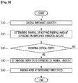
- FIG. 9 is a flowchart illustrating a method of operating a rain sensor according to the embodiment of the present invention.
- the rain sensor 20 senses a change in impedance depending on whether rainfall occurs or not in the windshield 10 of the vehicle in step S10.
- the rain sensor 20 transmits sensing information on the sensed impedance variation to the control unit 70.
- the control unit 70 receives sensing information indicating the impedance variation, and determines presence of rainfall and a rainfall amount depending on an amount of impedance variation based on the sensed information in step S20.
- control unit 70 determines whether the rainfall amount exceeds a critical point or not in step S30. Whether or not the critical point is exceeded may be determined by whether the impedance variation amount exceeds the critical point.
- control unit 70 determines a driving speed of the wiper 40 to be driven depending on the rainfall amount in step S 40.
- control unit 70 drives the wiper 40 at the determined driving speed in step S50.
Landscapes
- Engineering & Computer Science (AREA)
- Chemical & Material Sciences (AREA)
- Life Sciences & Earth Sciences (AREA)
- Mechanical Engineering (AREA)
- Automation & Control Theory (AREA)
- Analytical Chemistry (AREA)
- General Physics & Mathematics (AREA)
- Pathology (AREA)
- Immunology (AREA)
- General Health & Medical Sciences (AREA)
- Biochemistry (AREA)
- Chemical Kinetics & Catalysis (AREA)
- Electrochemistry (AREA)
- Physics & Mathematics (AREA)
- Health & Medical Sciences (AREA)
- Environmental & Geological Engineering (AREA)
- Hydrology & Water Resources (AREA)
- Environmental Sciences (AREA)
- Atmospheric Sciences (AREA)
- Ecology (AREA)
- Biodiversity & Conservation Biology (AREA)
- Investigating Or Analyzing Materials By The Use Of Electric Means (AREA)
Applications Claiming Priority (2)
| Application Number | Priority Date | Filing Date | Title |
|---|---|---|---|
| KR1020150034390A KR102327610B1 (ko) | 2015-03-12 | 2015-03-12 | 레인 센서 및 이를 포함하는 와이퍼 구동 장치 |
| PCT/KR2016/002197 WO2016144054A1 (ko) | 2015-03-12 | 2016-03-04 | 레인 센서 및 이를 포함하는 와이퍼 구동 장치 |
Publications (3)
| Publication Number | Publication Date |
|---|---|
| EP3269603A1 true EP3269603A1 (de) | 2018-01-17 |
| EP3269603A4 EP3269603A4 (de) | 2018-02-21 |
| EP3269603B1 EP3269603B1 (de) | 2021-06-23 |
Family
ID=56880279
Family Applications (1)
| Application Number | Title | Priority Date | Filing Date |
|---|---|---|---|
| EP16761941.0A Active EP3269603B1 (de) | 2015-03-12 | 2016-03-04 | Wischeransteuerungsvorrichtung |
Country Status (5)
| Country | Link |
|---|---|
| US (1) | US10407028B2 (de) |
| EP (1) | EP3269603B1 (de) |
| KR (1) | KR102327610B1 (de) |
| CN (1) | CN107428315B (de) |
| WO (1) | WO2016144054A1 (de) |
Families Citing this family (11)
| Publication number | Priority date | Publication date | Assignee | Title |
|---|---|---|---|---|
| KR102354521B1 (ko) * | 2015-03-05 | 2022-01-24 | 엘지이노텍 주식회사 | 감지 모듈 및 이를 포함하는 냉장고 |
| KR102327610B1 (ko) * | 2015-03-12 | 2021-11-17 | 엘지이노텍 주식회사 | 레인 센서 및 이를 포함하는 와이퍼 구동 장치 |
| KR102503129B1 (ko) * | 2016-07-22 | 2023-02-23 | 엘지이노텍 주식회사 | 레인 센서 및 이를 포함하는 와이퍼 구동 장치 |
| KR102651624B1 (ko) * | 2016-12-12 | 2024-03-26 | 엘지이노텍 주식회사 | 유리 조성물, 이를 포함하는 감지 장치 및 용기 |
| KR20180069513A (ko) * | 2016-12-15 | 2018-06-25 | 엘지이노텍 주식회사 | 물체 감지 센서 및 이를 포함하는 차량 안전 장치 |
| KR102444407B1 (ko) * | 2017-04-19 | 2022-09-20 | 엘지이노텍 주식회사 | 감지 장치 |
| KR102318450B1 (ko) * | 2017-04-19 | 2021-10-28 | 엘지이노텍 주식회사 | 감지 장치 및 이를 포함하는 와이퍼 구동 장치 |
| KR102383683B1 (ko) * | 2017-09-28 | 2022-04-07 | 엘지이노텍 주식회사 | 감지 장치 |
| KR102361449B1 (ko) * | 2017-10-19 | 2022-02-10 | 엘지이노텍 주식회사 | 감지장치 |
| CN114035245A (zh) * | 2021-10-20 | 2022-02-11 | 深圳市欧赛特电子有限公司 | 雨量检测装置及方法 |
| KR102454594B1 (ko) | 2022-02-25 | 2022-10-14 | 주식회사 다모아텍 | 진동을 감지하는 우적 센서 및 그 동작 방법 |
Family Cites Families (28)
| Publication number | Priority date | Publication date | Assignee | Title |
|---|---|---|---|---|
| JPS5431715B2 (de) | 1972-09-20 | 1979-10-09 | ||
| US4783876A (en) * | 1985-09-03 | 1988-11-15 | Toyota Jidosha Kabushiki Kaisha | Concealable wiper apparatus for vehicle |
| US6806722B2 (en) | 2001-12-07 | 2004-10-19 | Samsung Electronics Co., Ltd. | Polymer-type humidity sensor |
| US6802205B2 (en) | 2002-02-28 | 2004-10-12 | Ppg Industries Ohio, Inc. | Moisture detection system and method of use thereof |
| US7948041B2 (en) * | 2005-05-19 | 2011-05-24 | Nanomix, Inc. | Sensor having a thin-film inhibition layer |
| US7204130B2 (en) * | 2002-12-03 | 2007-04-17 | Ppg Industries Ohio, Inc. | Windshield moisture detector |
| CN1217204C (zh) * | 2003-09-19 | 2005-08-31 | 孙滕谌 | 平面电容式汽车玻璃自动雨刷系统智能传感器 |
| BE1016680A3 (fr) * | 2005-07-13 | 2007-04-03 | Glaverbel | Vitrage comportant un detecteur de pluie capacitif. |
| US7561055B2 (en) * | 2006-01-10 | 2009-07-14 | Guardian Industries Corp. | Rain sensor with capacitive-inclusive circuit |
| US9371032B2 (en) * | 2006-01-10 | 2016-06-21 | Guardian Industries Corp. | Moisture sensor and/or defogger with Bayesian improvements, and related methods |
| JP4587317B2 (ja) * | 2006-01-24 | 2010-11-24 | 国立大学法人岐阜大学 | 接近センサ及び接近・接触センサ |
| CN200938949Y (zh) | 2006-06-19 | 2007-08-29 | 厦门进雄企业有限公司 | 一种能改变成椅子的桌椅结合体 |
| JP2008082712A (ja) * | 2006-09-25 | 2008-04-10 | Gifu Univ | 圧力センサ素子 |
| GB0721682D0 (en) * | 2007-11-05 | 2007-12-19 | Pilkington Automotive D Gmbh | Wired glazing |
| DE102008003219A1 (de) * | 2008-01-04 | 2009-07-09 | Saint-Gobain Sekurit Deutschland Gmbh & Co. Kg | Glasscheibe sowie Glasscheibenanordnung |
| KR100943401B1 (ko) | 2008-06-05 | 2010-02-19 | 우리산업 주식회사 | 차량용 레인센서 및 그 센싱방법 |
| JP2010096609A (ja) * | 2008-10-16 | 2010-04-30 | Gifu Univ | 圧力センサ素子 |
| JP5267932B2 (ja) * | 2008-11-11 | 2013-08-21 | 株式会社フジクラ | 位置検出装置 |
| JP2010133775A (ja) * | 2008-12-03 | 2010-06-17 | Gifu Univ | 微小差圧測定用の差圧センサ |
| JP2010249531A (ja) | 2009-04-10 | 2010-11-04 | Fujikura Ltd | 雨滴検知装置およびワイパー動作制御装置 |
| JP5353612B2 (ja) * | 2009-10-01 | 2013-11-27 | 東レ株式会社 | 電極用金属化フィルム |
| US8576083B2 (en) | 2009-12-10 | 2013-11-05 | Enterprise Electronics, Llc | Rain detector |
| JP2011232050A (ja) | 2010-04-23 | 2011-11-17 | Asmo Co Ltd | 水滴検出装置 |
| US20120286813A1 (en) | 2011-05-12 | 2012-11-15 | Murphy Morgan D | Windshield moisture detector |
| KR20140048501A (ko) | 2012-10-16 | 2014-04-24 | (주)에프에스씨 | 전계 변화 효과 응용 레인 센서 |
| KR102262519B1 (ko) * | 2015-02-06 | 2021-06-09 | 엘지이노텍 주식회사 | 운송 수단용 센서, 그 센싱 방법 및 운송 수단 시스템 |
| KR102354521B1 (ko) | 2015-03-05 | 2022-01-24 | 엘지이노텍 주식회사 | 감지 모듈 및 이를 포함하는 냉장고 |
| KR102327610B1 (ko) * | 2015-03-12 | 2021-11-17 | 엘지이노텍 주식회사 | 레인 센서 및 이를 포함하는 와이퍼 구동 장치 |
-
2015
- 2015-03-12 KR KR1020150034390A patent/KR102327610B1/ko active Active
-
2016
- 2016-03-04 US US15/556,924 patent/US10407028B2/en active Active
- 2016-03-04 CN CN201680015286.8A patent/CN107428315B/zh not_active Expired - Fee Related
- 2016-03-04 WO PCT/KR2016/002197 patent/WO2016144054A1/ko not_active Ceased
- 2016-03-04 EP EP16761941.0A patent/EP3269603B1/de active Active
Also Published As
| Publication number | Publication date |
|---|---|
| KR102327610B1 (ko) | 2021-11-17 |
| EP3269603B1 (de) | 2021-06-23 |
| EP3269603A4 (de) | 2018-02-21 |
| CN107428315A (zh) | 2017-12-01 |
| CN107428315B (zh) | 2021-02-05 |
| KR20160109621A (ko) | 2016-09-21 |
| US10407028B2 (en) | 2019-09-10 |
| US20180244244A1 (en) | 2018-08-30 |
| WO2016144054A1 (ko) | 2016-09-15 |
Similar Documents
| Publication | Publication Date | Title |
|---|---|---|
| US10407028B2 (en) | Rain sensor and wiper driving apparatus comprising same | |
| US7204130B2 (en) | Windshield moisture detector | |
| AU2003293233B2 (en) | Moisture detection system and method of use thereof | |
| US12158441B2 (en) | Rain detection device, garden appliance having the rain detection device, and method for sensing rain drops on a surface by means of a rain detection device | |
| US7296461B2 (en) | Temperature compensated windshield moisture detector | |
| KR101122686B1 (ko) | 자동차 앞유리의 환경 변화를 검출하는 장치 및 방법 | |
| CN103434487A (zh) | 用于挡风玻璃上的雨检测的方法和装置 | |
| KR102503129B1 (ko) | 레인 센서 및 이를 포함하는 와이퍼 구동 장치 | |
| KR20160096901A (ko) | 운송 수단용 센서, 그 센싱 방법 및 운송 수단 시스템 | |
| CN1343167A (zh) | 汽车照明装置的自动开关装置 | |
| EP3333024B1 (de) | Vorrichtung und verfahren zum scheibenwischerantrieb | |
| EP1480858B1 (de) | Feuchtigkeitsdetektionssystem und methode seiner verwendung | |
| KR101743139B1 (ko) | 탄소마이크로코일수분감지센서 및 이를 구비한 시스템들 | |
| US7263875B2 (en) | Multi-layer windshield moisture detector | |
| KR102564311B1 (ko) | 복합형 센서 패키지, 복합 감지 장치 및 이의 동작 방법 | |
| KR20190093009A (ko) | 감지 장치 및 이의 동작 방법 | |
| KR102441502B1 (ko) | 센서, 레인 감지 장치 및 이의 제조 방법 | |
| CN115230800A (zh) | 带有自适应电容式触摸识别器的方向盘、相关的组件和机动车辆 | |
| CN220053737U (zh) | 一种雨量感知组件以及雨刮系统 | |
| KR102669123B1 (ko) | 액적 제거 장치 및 그 방법 | |
| JP2008195396A (ja) | 水分検出システムおよびその使用方法 |
Legal Events
| Date | Code | Title | Description |
|---|---|---|---|
| STAA | Information on the status of an ep patent application or granted ep patent |
Free format text: STATUS: THE INTERNATIONAL PUBLICATION HAS BEEN MADE |
|
| PUAI | Public reference made under article 153(3) epc to a published international application that has entered the european phase |
Free format text: ORIGINAL CODE: 0009012 |
|
| STAA | Information on the status of an ep patent application or granted ep patent |
Free format text: STATUS: REQUEST FOR EXAMINATION WAS MADE |
|
| 17P | Request for examination filed |
Effective date: 20171005 |
|
| AK | Designated contracting states |
Kind code of ref document: A1 Designated state(s): AL AT BE BG CH CY CZ DE DK EE ES FI FR GB GR HR HU IE IS IT LI LT LU LV MC MK MT NL NO PL PT RO RS SE SI SK SM TR |
|
| AX | Request for extension of the european patent |
Extension state: BA ME |
|
| A4 | Supplementary search report drawn up and despatched |
Effective date: 20180124 |
|
| RIC1 | Information provided on ipc code assigned before grant |
Ipc: B60S 1/08 20060101AFI20180118BHEP Ipc: G01N 27/22 20060101ALI20180118BHEP |
|
| DAV | Request for validation of the european patent (deleted) | ||
| DAX | Request for extension of the european patent (deleted) | ||
| GRAP | Despatch of communication of intention to grant a patent |
Free format text: ORIGINAL CODE: EPIDOSNIGR1 |
|
| STAA | Information on the status of an ep patent application or granted ep patent |
Free format text: STATUS: GRANT OF PATENT IS INTENDED |
|
| INTG | Intention to grant announced |
Effective date: 20210205 |
|
| GRAS | Grant fee paid |
Free format text: ORIGINAL CODE: EPIDOSNIGR3 |
|
| GRAA | (expected) grant |
Free format text: ORIGINAL CODE: 0009210 |
|
| STAA | Information on the status of an ep patent application or granted ep patent |
Free format text: STATUS: THE PATENT HAS BEEN GRANTED |
|
| AK | Designated contracting states |
Kind code of ref document: B1 Designated state(s): AL AT BE BG CH CY CZ DE DK EE ES FI FR GB GR HR HU IE IS IT LI LT LU LV MC MK MT NL NO PL PT RO RS SE SI SK SM TR |
|
| REG | Reference to a national code |
Ref country code: GB Ref legal event code: FG4D |
|
| REG | Reference to a national code |
Ref country code: CH Ref legal event code: EP |
|
| REG | Reference to a national code |
Ref country code: DE Ref legal event code: R096 Ref document number: 602016059664 Country of ref document: DE Ref country code: AT Ref legal event code: REF Ref document number: 1404057 Country of ref document: AT Kind code of ref document: T Effective date: 20210715 |
|
| REG | Reference to a national code |
Ref country code: IE Ref legal event code: FG4D |
|
| REG | Reference to a national code |
Ref country code: LT Ref legal event code: MG9D |
|
| PG25 | Lapsed in a contracting state [announced via postgrant information from national office to epo] |
Ref country code: LT Free format text: LAPSE BECAUSE OF FAILURE TO SUBMIT A TRANSLATION OF THE DESCRIPTION OR TO PAY THE FEE WITHIN THE PRESCRIBED TIME-LIMIT Effective date: 20210623 Ref country code: FI Free format text: LAPSE BECAUSE OF FAILURE TO SUBMIT A TRANSLATION OF THE DESCRIPTION OR TO PAY THE FEE WITHIN THE PRESCRIBED TIME-LIMIT Effective date: 20210623 Ref country code: HR Free format text: LAPSE BECAUSE OF FAILURE TO SUBMIT A TRANSLATION OF THE DESCRIPTION OR TO PAY THE FEE WITHIN THE PRESCRIBED TIME-LIMIT Effective date: 20210623 Ref country code: BG Free format text: LAPSE BECAUSE OF FAILURE TO SUBMIT A TRANSLATION OF THE DESCRIPTION OR TO PAY THE FEE WITHIN THE PRESCRIBED TIME-LIMIT Effective date: 20210923 |
|
| REG | Reference to a national code |
Ref country code: AT Ref legal event code: MK05 Ref document number: 1404057 Country of ref document: AT Kind code of ref document: T Effective date: 20210623 |
|
| PG25 | Lapsed in a contracting state [announced via postgrant information from national office to epo] |
Ref country code: LV Free format text: LAPSE BECAUSE OF FAILURE TO SUBMIT A TRANSLATION OF THE DESCRIPTION OR TO PAY THE FEE WITHIN THE PRESCRIBED TIME-LIMIT Effective date: 20210623 Ref country code: GR Free format text: LAPSE BECAUSE OF FAILURE TO SUBMIT A TRANSLATION OF THE DESCRIPTION OR TO PAY THE FEE WITHIN THE PRESCRIBED TIME-LIMIT Effective date: 20210924 Ref country code: SE Free format text: LAPSE BECAUSE OF FAILURE TO SUBMIT A TRANSLATION OF THE DESCRIPTION OR TO PAY THE FEE WITHIN THE PRESCRIBED TIME-LIMIT Effective date: 20210623 Ref country code: RS Free format text: LAPSE BECAUSE OF FAILURE TO SUBMIT A TRANSLATION OF THE DESCRIPTION OR TO PAY THE FEE WITHIN THE PRESCRIBED TIME-LIMIT Effective date: 20210623 Ref country code: NO Free format text: LAPSE BECAUSE OF FAILURE TO SUBMIT A TRANSLATION OF THE DESCRIPTION OR TO PAY THE FEE WITHIN THE PRESCRIBED TIME-LIMIT Effective date: 20210923 |
|
| REG | Reference to a national code |
Ref country code: NL Ref legal event code: MP Effective date: 20210623 |
|
| PG25 | Lapsed in a contracting state [announced via postgrant information from national office to epo] |
Ref country code: SM Free format text: LAPSE BECAUSE OF FAILURE TO SUBMIT A TRANSLATION OF THE DESCRIPTION OR TO PAY THE FEE WITHIN THE PRESCRIBED TIME-LIMIT Effective date: 20210623 Ref country code: SK Free format text: LAPSE BECAUSE OF FAILURE TO SUBMIT A TRANSLATION OF THE DESCRIPTION OR TO PAY THE FEE WITHIN THE PRESCRIBED TIME-LIMIT Effective date: 20210623 Ref country code: EE Free format text: LAPSE BECAUSE OF FAILURE TO SUBMIT A TRANSLATION OF THE DESCRIPTION OR TO PAY THE FEE WITHIN THE PRESCRIBED TIME-LIMIT Effective date: 20210623 Ref country code: CZ Free format text: LAPSE BECAUSE OF FAILURE TO SUBMIT A TRANSLATION OF THE DESCRIPTION OR TO PAY THE FEE WITHIN THE PRESCRIBED TIME-LIMIT Effective date: 20210623 Ref country code: RO Free format text: LAPSE BECAUSE OF FAILURE TO SUBMIT A TRANSLATION OF THE DESCRIPTION OR TO PAY THE FEE WITHIN THE PRESCRIBED TIME-LIMIT Effective date: 20210623 Ref country code: PT Free format text: LAPSE BECAUSE OF FAILURE TO SUBMIT A TRANSLATION OF THE DESCRIPTION OR TO PAY THE FEE WITHIN THE PRESCRIBED TIME-LIMIT Effective date: 20211025 Ref country code: NL Free format text: LAPSE BECAUSE OF FAILURE TO SUBMIT A TRANSLATION OF THE DESCRIPTION OR TO PAY THE FEE WITHIN THE PRESCRIBED TIME-LIMIT Effective date: 20210623 Ref country code: ES Free format text: LAPSE BECAUSE OF FAILURE TO SUBMIT A TRANSLATION OF THE DESCRIPTION OR TO PAY THE FEE WITHIN THE PRESCRIBED TIME-LIMIT Effective date: 20210623 Ref country code: AT Free format text: LAPSE BECAUSE OF FAILURE TO SUBMIT A TRANSLATION OF THE DESCRIPTION OR TO PAY THE FEE WITHIN THE PRESCRIBED TIME-LIMIT Effective date: 20210623 |
|
| PG25 | Lapsed in a contracting state [announced via postgrant information from national office to epo] |
Ref country code: PL Free format text: LAPSE BECAUSE OF FAILURE TO SUBMIT A TRANSLATION OF THE DESCRIPTION OR TO PAY THE FEE WITHIN THE PRESCRIBED TIME-LIMIT Effective date: 20210623 |
|
| REG | Reference to a national code |
Ref country code: DE Ref legal event code: R097 Ref document number: 602016059664 Country of ref document: DE |
|
| PG25 | Lapsed in a contracting state [announced via postgrant information from national office to epo] |
Ref country code: DK Free format text: LAPSE BECAUSE OF FAILURE TO SUBMIT A TRANSLATION OF THE DESCRIPTION OR TO PAY THE FEE WITHIN THE PRESCRIBED TIME-LIMIT Effective date: 20210623 |
|
| PLBE | No opposition filed within time limit |
Free format text: ORIGINAL CODE: 0009261 |
|
| STAA | Information on the status of an ep patent application or granted ep patent |
Free format text: STATUS: NO OPPOSITION FILED WITHIN TIME LIMIT |
|
| 26N | No opposition filed |
Effective date: 20220324 |
|
| PG25 | Lapsed in a contracting state [announced via postgrant information from national office to epo] |
Ref country code: AL Free format text: LAPSE BECAUSE OF FAILURE TO SUBMIT A TRANSLATION OF THE DESCRIPTION OR TO PAY THE FEE WITHIN THE PRESCRIBED TIME-LIMIT Effective date: 20210623 |
|
| PG25 | Lapsed in a contracting state [announced via postgrant information from national office to epo] |
Ref country code: IT Free format text: LAPSE BECAUSE OF FAILURE TO SUBMIT A TRANSLATION OF THE DESCRIPTION OR TO PAY THE FEE WITHIN THE PRESCRIBED TIME-LIMIT Effective date: 20210623 |
|
| PG25 | Lapsed in a contracting state [announced via postgrant information from national office to epo] |
Ref country code: MC Free format text: LAPSE BECAUSE OF FAILURE TO SUBMIT A TRANSLATION OF THE DESCRIPTION OR TO PAY THE FEE WITHIN THE PRESCRIBED TIME-LIMIT Effective date: 20210623 |
|
| REG | Reference to a national code |
Ref country code: CH Ref legal event code: PL |
|
| REG | Reference to a national code |
Ref country code: BE Ref legal event code: MM Effective date: 20220331 |
|
| PG25 | Lapsed in a contracting state [announced via postgrant information from national office to epo] |
Ref country code: LU Free format text: LAPSE BECAUSE OF NON-PAYMENT OF DUE FEES Effective date: 20220304 Ref country code: LI Free format text: LAPSE BECAUSE OF NON-PAYMENT OF DUE FEES Effective date: 20220331 Ref country code: IE Free format text: LAPSE BECAUSE OF NON-PAYMENT OF DUE FEES Effective date: 20220304 Ref country code: FR Free format text: LAPSE BECAUSE OF NON-PAYMENT OF DUE FEES Effective date: 20220331 Ref country code: CH Free format text: LAPSE BECAUSE OF NON-PAYMENT OF DUE FEES Effective date: 20220331 |
|
| PG25 | Lapsed in a contracting state [announced via postgrant information from national office to epo] |
Ref country code: BE Free format text: LAPSE BECAUSE OF NON-PAYMENT OF DUE FEES Effective date: 20220331 |
|
| PGFP | Annual fee paid to national office [announced via postgrant information from national office to epo] |
Ref country code: GB Payment date: 20230220 Year of fee payment: 8 Ref country code: DE Payment date: 20230220 Year of fee payment: 8 |
|
| PG25 | Lapsed in a contracting state [announced via postgrant information from national office to epo] |
Ref country code: HU Free format text: LAPSE BECAUSE OF FAILURE TO SUBMIT A TRANSLATION OF THE DESCRIPTION OR TO PAY THE FEE WITHIN THE PRESCRIBED TIME-LIMIT; INVALID AB INITIO Effective date: 20160304 |
|
| PG25 | Lapsed in a contracting state [announced via postgrant information from national office to epo] |
Ref country code: MK Free format text: LAPSE BECAUSE OF FAILURE TO SUBMIT A TRANSLATION OF THE DESCRIPTION OR TO PAY THE FEE WITHIN THE PRESCRIBED TIME-LIMIT Effective date: 20210623 Ref country code: CY Free format text: LAPSE BECAUSE OF FAILURE TO SUBMIT A TRANSLATION OF THE DESCRIPTION OR TO PAY THE FEE WITHIN THE PRESCRIBED TIME-LIMIT Effective date: 20210623 |
|
| PG25 | Lapsed in a contracting state [announced via postgrant information from national office to epo] |
Ref country code: TR Free format text: LAPSE BECAUSE OF FAILURE TO SUBMIT A TRANSLATION OF THE DESCRIPTION OR TO PAY THE FEE WITHIN THE PRESCRIBED TIME-LIMIT Effective date: 20210623 |
|
| PG25 | Lapsed in a contracting state [announced via postgrant information from national office to epo] |
Ref country code: MT Free format text: LAPSE BECAUSE OF FAILURE TO SUBMIT A TRANSLATION OF THE DESCRIPTION OR TO PAY THE FEE WITHIN THE PRESCRIBED TIME-LIMIT Effective date: 20210623 |
|
| REG | Reference to a national code |
Ref country code: DE Ref legal event code: R119 Ref document number: 602016059664 Country of ref document: DE |
|
| GBPC | Gb: european patent ceased through non-payment of renewal fee |
Effective date: 20240304 |
|
| PG25 | Lapsed in a contracting state [announced via postgrant information from national office to epo] |
Ref country code: DE Free format text: LAPSE BECAUSE OF NON-PAYMENT OF DUE FEES Effective date: 20241001 |
|
| PG25 | Lapsed in a contracting state [announced via postgrant information from national office to epo] |
Ref country code: GB Free format text: LAPSE BECAUSE OF NON-PAYMENT OF DUE FEES Effective date: 20240304 |
|
| PG25 | Lapsed in a contracting state [announced via postgrant information from national office to epo] |
Ref country code: GB Free format text: LAPSE BECAUSE OF NON-PAYMENT OF DUE FEES Effective date: 20240304 Ref country code: DE Free format text: LAPSE BECAUSE OF NON-PAYMENT OF DUE FEES Effective date: 20241001 |