EP3270786B1 - Détection de mouvement automatique - Google Patents
Détection de mouvement automatique Download PDFInfo
- Publication number
- EP3270786B1 EP3270786B1 EP16707718.9A EP16707718A EP3270786B1 EP 3270786 B1 EP3270786 B1 EP 3270786B1 EP 16707718 A EP16707718 A EP 16707718A EP 3270786 B1 EP3270786 B1 EP 3270786B1
- Authority
- EP
- European Patent Office
- Prior art keywords
- images
- fluoroscopic
- sequence
- image
- landmark
- Prior art date
- Legal status (The legal status is an assumption and is not a legal conclusion. Google has not performed a legal analysis and makes no representation as to the accuracy of the status listed.)
- Active
Links
Images


Classifications
-
- A—HUMAN NECESSITIES
- A61—MEDICAL OR VETERINARY SCIENCE; HYGIENE
- A61B—DIAGNOSIS; SURGERY; IDENTIFICATION
- A61B6/00—Apparatus or devices for radiation diagnosis; Apparatus or devices for radiation diagnosis combined with radiation therapy equipment
- A61B6/12—Arrangements for detecting or locating foreign bodies
-
- A—HUMAN NECESSITIES
- A61—MEDICAL OR VETERINARY SCIENCE; HYGIENE
- A61B—DIAGNOSIS; SURGERY; IDENTIFICATION
- A61B34/00—Computer-aided surgery; Manipulators or robots specially adapted for use in surgery
- A61B34/20—Surgical navigation systems; Devices for tracking or guiding surgical instruments, e.g. for frameless stereotaxis
-
- A—HUMAN NECESSITIES
- A61—MEDICAL OR VETERINARY SCIENCE; HYGIENE
- A61B—DIAGNOSIS; SURGERY; IDENTIFICATION
- A61B6/00—Apparatus or devices for radiation diagnosis; Apparatus or devices for radiation diagnosis combined with radiation therapy equipment
- A61B6/46—Arrangements for interfacing with the operator or the patient
- A61B6/461—Displaying means of special interest
-
- A—HUMAN NECESSITIES
- A61—MEDICAL OR VETERINARY SCIENCE; HYGIENE
- A61B—DIAGNOSIS; SURGERY; IDENTIFICATION
- A61B6/00—Apparatus or devices for radiation diagnosis; Apparatus or devices for radiation diagnosis combined with radiation therapy equipment
- A61B6/48—Diagnostic techniques
- A61B6/486—Diagnostic techniques involving generating temporal series of image data
- A61B6/487—Diagnostic techniques involving generating temporal series of image data involving fluoroscopy
-
- A—HUMAN NECESSITIES
- A61—MEDICAL OR VETERINARY SCIENCE; HYGIENE
- A61B—DIAGNOSIS; SURGERY; IDENTIFICATION
- A61B6/00—Apparatus or devices for radiation diagnosis; Apparatus or devices for radiation diagnosis combined with radiation therapy equipment
- A61B6/50—Apparatus or devices for radiation diagnosis; Apparatus or devices for radiation diagnosis combined with radiation therapy equipment specially adapted for specific body parts; specially adapted for specific clinical applications
- A61B6/504—Apparatus or devices for radiation diagnosis; Apparatus or devices for radiation diagnosis combined with radiation therapy equipment specially adapted for specific body parts; specially adapted for specific clinical applications for diagnosis of blood vessels, e.g. by angiography
-
- G—PHYSICS
- G06—COMPUTING OR CALCULATING; COUNTING
- G06T—IMAGE DATA PROCESSING OR GENERATION, IN GENERAL
- G06T7/00—Image analysis
- G06T7/0002—Inspection of images, e.g. flaw detection
- G06T7/0012—Biomedical image inspection
-
- G—PHYSICS
- G06—COMPUTING OR CALCULATING; COUNTING
- G06T—IMAGE DATA PROCESSING OR GENERATION, IN GENERAL
- G06T7/00—Image analysis
- G06T7/20—Analysis of motion
- G06T7/246—Analysis of motion using feature-based methods, e.g. the tracking of corners or segments
-
- A—HUMAN NECESSITIES
- A61—MEDICAL OR VETERINARY SCIENCE; HYGIENE
- A61B—DIAGNOSIS; SURGERY; IDENTIFICATION
- A61B34/00—Computer-aided surgery; Manipulators or robots specially adapted for use in surgery
- A61B34/20—Surgical navigation systems; Devices for tracking or guiding surgical instruments, e.g. for frameless stereotaxis
- A61B2034/2046—Tracking techniques
- A61B2034/2065—Tracking using image or pattern recognition
-
- A—HUMAN NECESSITIES
- A61—MEDICAL OR VETERINARY SCIENCE; HYGIENE
- A61B—DIAGNOSIS; SURGERY; IDENTIFICATION
- A61B90/00—Instruments, implements or accessories specially adapted for surgery or diagnosis and not covered by any of the groups A61B1/00 - A61B50/00, e.g. for luxation treatment or for protecting wound edges
- A61B90/36—Image-producing devices or illumination devices not otherwise provided for
- A61B2090/363—Use of fiducial points
-
- A—HUMAN NECESSITIES
- A61—MEDICAL OR VETERINARY SCIENCE; HYGIENE
- A61M—DEVICES FOR INTRODUCING MEDIA INTO, OR ONTO, THE BODY; DEVICES FOR TRANSDUCING BODY MEDIA OR FOR TAKING MEDIA FROM THE BODY; DEVICES FOR PRODUCING OR ENDING SLEEP OR STUPOR
- A61M25/00—Catheters; Hollow probes
- A61M25/01—Introducing, guiding, advancing, emplacing or holding catheters
- A61M25/09—Guide wires
- A61M2025/09166—Guide wires having radio-opaque features
-
- G—PHYSICS
- G06—COMPUTING OR CALCULATING; COUNTING
- G06T—IMAGE DATA PROCESSING OR GENERATION, IN GENERAL
- G06T2207/00—Indexing scheme for image analysis or image enhancement
- G06T2207/10—Image acquisition modality
- G06T2207/10016—Video; Image sequence
-
- G—PHYSICS
- G06—COMPUTING OR CALCULATING; COUNTING
- G06T—IMAGE DATA PROCESSING OR GENERATION, IN GENERAL
- G06T2207/00—Indexing scheme for image analysis or image enhancement
- G06T2207/10—Image acquisition modality
- G06T2207/10116—X-ray image
- G06T2207/10121—Fluoroscopy
-
- G—PHYSICS
- G06—COMPUTING OR CALCULATING; COUNTING
- G06T—IMAGE DATA PROCESSING OR GENERATION, IN GENERAL
- G06T2207/00—Indexing scheme for image analysis or image enhancement
- G06T2207/30—Subject of image; Context of image processing
- G06T2207/30004—Biomedical image processing
- G06T2207/30021—Catheter; Guide wire
-
- G—PHYSICS
- G06—COMPUTING OR CALCULATING; COUNTING
- G06T—IMAGE DATA PROCESSING OR GENERATION, IN GENERAL
- G06T2207/00—Indexing scheme for image analysis or image enhancement
- G06T2207/30—Subject of image; Context of image processing
- G06T2207/30004—Biomedical image processing
- G06T2207/30101—Blood vessel; Artery; Vein; Vascular
- G06T2207/30104—Vascular flow; Blood flow; Perfusion
-
- G—PHYSICS
- G06—COMPUTING OR CALCULATING; COUNTING
- G06V—IMAGE OR VIDEO RECOGNITION OR UNDERSTANDING
- G06V2201/00—Indexing scheme relating to image or video recognition or understanding
- G06V2201/03—Recognition of patterns in medical or anatomical images
- G06V2201/034—Recognition of patterns in medical or anatomical images of medical instruments
Definitions
- the present invention relates to method of and system for automatic detection of an event in which a device is leaving a stable position relative to and within an anatomy.
- the invention relates to method of and system for automatic detection of movement of a device relative to and within an anatomy.
- the invention relates to a corresponding computer program.
- 3D roadmapping is thus of importance in many interventions under X-ray guidance. Since the vascular anatomy is almost not visible in fluoroscopic images without the injection of a contrast agent, a registered (either statically or dynamically) 3D roadmap provides an interventionists with a visual reference for various tasks such as navigation, positioning or deploying a device and/or assessment of the outcome.
- Static motion compensation involves registering the 3D roadmap to find a single geometric transformation for the entire fluoroscopic sequence, whereas dynamic motion compensation requires finding the right geometric transformation for each frame in the sequence.
- the first approach consists in tracking anatomical landmarks connected to the vascular anatomy, having the same motion as the vessels, as for example in the context of valve positioning and deployment during a TAVI procedure.
- the second approach consists in tracking a device connected to the vascular anatomy and thus having a similar motion. Devices are clearly visible and are good candidates for dynamic motion compensation algorithms.
- a navigation system can help the cardiologists by providing a cardiac roadmap displayed next or overlaid on the live fluoroscopy pictures.
- this cardiac roadmap represents the vessel network acquired during angiography.
- WO 2011/039681 A1 describes a method and a medical imaging system for accurate positioning for vessel intervention procedures.
- at least one x-ray image of a vessel region of interest is acquired with injected contrast agent.
- vessel information data is identified within the at least one acquired image.
- first calcification features of the vessel in the vessel region of interest in the at least one acquired image are detected.
- vessel representation is generated using the vessel information data and the detected calcification features.
- at least one current fluoroscopic image of the vessel region of interest is acquired.
- second calcification features of the vessel in the vessel region of interest in the at least one current fluoroscopic image are detected, wherein the second calcification features are according to the first calcification features.
- the vessel representation is registered with the fluoroscopic image, wherein the calcification features are used for the registration.
- a composite image is generated by combining the vessel representation with the at least one fluoroscopic image.
- the composite image is finally displayed.
- WO 2004/034329 A2 there is described a basic method for realizing cardiac roadmapping, relying on the extraction of the cardiac and respiratory cycles, and on the matching of those cycles between the angiogram images (in filled state) and the live roadmapping, relying on the extraction of the cardiac and respiratory cycles, and on the matching of those cycles between the angiogram images (in filled state) and the live images.
- US 2013/0331687 describes a method for compensating cardiac and respiratory motion in atrial fibrillation ablation procedures includes (a) simultaneously determining a position of a circumferential mapping (CFM) catheter and a coronary sinus (CS) catheter in two consecutive image frames of a series of first 2-D image frames; (b) determining a distance between a virtual electrode on the CS catheter and a center of the CFM catheter for a first image frame of the two consecutive image frames, and for a second image frame of the two consecutive image frames; and (c) if an absolute difference of the distance for the first image frame and the distance for the second image frame is greater than a predetermined threshold, compensating for motion of the CFM catheter in a second 2-D image.
- CFM circumferential mapping
- CS coronary sinus
- the present invention suggests the presence of both the device and the anatomical landmarks.
- a method is proposed for automatic device unlocking detection using anatomical landmarks which, coupled with device-based motion compensation, makes it possible to design a fully automatic dynamic motion compensation approach.
- a method for automatic detection of an event in which a device is leaving a stable position relative to and within an anatomy comprises the steps of receiving a sequence of fluoroscopic images, detecting a device in at least two of the fluoroscopic determining a motion field of the detected device in the sequence of fluoroscopic images, generating a sequence of integrated images by integrating the sequence of fluoroscopic taking into consideration the motion field, determining a saliency metric based on the integrated images, and identifying a landmark in the integrated images based on the saliency metric. Further, it may be determined as to whether the landmark is moving relative to the device, based on a variation of the saliency metric.
- a device or a portion of interest of a device may be detected in a fluoroscopy image manually or by means of automatic procedures utilizing appropriate image processing computer software. Based on such detection, also the area surrounding the portion of the instrument may be defined manually by for example input, or may be defined automatically according to a previously determined procedure or software algorithms. It will be understood that a definition of an area may be performed automatically after a portion of a device is detected manually, or the area maybe defined manually after the system has detected aspects in a fluoroscopy image including a device, and supposed a portion by for example high-lighting the same.
- a device may be an interventional instrument which can be introduced into a body for therapeutic or diagnostic purposes, for example a catheter for insertion of a stent into a vasculature.
- a portion of interest of such a device may particularly be a tip portion of the device, i.e. a distal end portion of a device, for example a distal portion of a catheter at which a stent is accommodated for introduction into a body.
- the instrument may be, on the one hand, a flexible or stiff catheter or wire tip or an electrode, and on the other hand also a biopsy device, a cannula or trocar. It can also be an endoprothesis such as a stent, an occluder (e.g. a Patent Foramen Oval occluder), an artificial valve, etc.
- a motion field is a mathematical function which give the motion of pixels, from a given image to another one.
- the motion field of the pigtail catheter indicates how and how much to displace the pigtail from its position in the current frame, to find its position in the next frame.
- a sequence of fluoroscopic images comprises a first fluoroscopic image and a second fluoroscopic image
- a determination of a motion field comprises a determination of a displacement of for example a device between a position detected in the first fluoroscopic image and a position detected in the second fluoroscopic image.
- a motion field may consequently comprise displacements of a plurality of pixels related to one device.
- a displacement of at least one pixel related to a device may be taken into consideration for integrating the plurality of, i.e. the at least two fluoroscopic images.
- saliency metric refers to a quantitative measure which allows highlighting regions having a desired property in the image.
- a saliency metric may be a map, computed from the integrated image, wherein the higher a pixel value, the more likely this pixel belongs to a structure having the same motion than the device. Structures are "salient” given a property. Here, this property is "having the same motion or displacement as the device”.
- saliency metric refers to a map including at least one salient structure which salient structure may be denoted as landmark. A landmark and in to enhance such structures or landmarks, which would be too faint to be detectable otherwise.
- the integration of the sequence of fluoroscopic images is a temporal integration. That is, the received sequence of fluoroscopic images is processed, i.e. integrated in accordance with the sequence in time in which these fluoroscopic images have been generated.
- the saliency metric may be newly determined for each newly received integrated image so that a sequence of saliency metrics is generated.
- the saliency metric may vary when comparing pixel values of landmarks in one saliency metric with another saliency metric. For example, when a pixel value of a landmark increases from one saliency metric to the next one, it is likely that the device is not displaced relative to the landmark. On the other hand, when a pixel value of a landmark decreases from one saliency metric to the next saliency metric, it can be assumed that the device is moving relative to the landmark.
- the method may further comprise the step of visualizing at least one fluoroscopic image out of the sequence of fluoroscopic images together with a roadmap as an overlay of the roadmap on the at least one fluoroscopic image.
- the roadmap may be masked when a motion of the landmark relative to the device (or vice versa) is determined as described above.
- an anatomical landmark may include a calcification in a vascular system. Otherwise, a landmark may also include an already implanted element like a stent or any other surgical implant or orthopedic implant which is already implanted in the vicinity of the device introduced into the vasculature.
- calcifications are pre-segmented from a preoperative 3D CT volume, they can be projected on the 2D sequence in real-time. Their 2D shape and appearance are thus known and can be used to improve the saliency metric.
- calcifications are pre-segmented from a preoperative 3D CT volume, their projection on the 2D sequence may be used to refine the region where temporal integration is performed.
- the region where the saliency metric is computed can be narrowed down by detecting and masking other devices first (e.g. the prosthetic aortic valve).
- detecting unlocking may trigger an alternative to the current tracking algorithm, e.g. calcifications tracking.
- a system for automatic detection of an event in which a device is leaving a stable position relative to and within an anatomy comprises, in general, a device for generating fluoroscopic images, and a processing device for processing the fluoroscopy images in accordance with the above described method.
- the system may further comprise a database providing at least one roadmap.
- the result of the method i.e. the achieved combined images, may be displayed on a suitable device, for example on a monitor.
- computer program for automatic detection of an event in which a device is leaving a stable position relative to and within an anatomy, wherein the computer program, when being executed on a processing device of a system, causes the system to perform the above described method.
- the method according to the invention may be performed substantially automatically, or at least predominantly automatically. Therefore, the computer program may comprise sets of instructions for gathering and at least temporarily storing at least two fluoroscopic images generated by an appropriate system, sets of instructions for identifying a device shown in the fluoroscopy images, sets of instructions for determining a motion field of the detected device in the fluoroscopic images, sets of instructions for integrating the fluoroscopic images based on the motion field, sets of instructions for determining a saliency metric based on the integrated images, sets of instructions for identifying a landmark in the integrated images based on the saliency metric, and sets of instructions for determining as to whether the landmark is moving relative to the device, based on a variation of the saliency metric.
- the computer program may comprise sets of instructions for loading data from a data base including previously recorded image information, or may comprise sets of instructions for information retrieval from a user.
- Such a computer program is preferably loaded into a work memory of a data processor.
- the data processor is thus equipped to carry out the method of the invention.
- the invention relates to a computer readable medium, such as a CD-ROM, at which the computer program may be stored.
- the computer program may also be presented over a network like the World Wide Web and can be downloaded into the work memory of a data processor from such a network.
- FIG 1 illustrates the principle of a method according to the invention. It will be understood that the steps described with respect to the method are major steps, wherein these major steps might be differentiated or divided into several sub steps. Furthermore, there might be also sub steps between these major steps. Therefore, a sub step is only mentioned if that step is important for the understanding of the principles of the method according to the invention.
- a TAVI procedure is considered in the following, where dynamic motion compensation is particularly useful during valve positioning and valve deployment.
- Patients undergoing TAVI interventions usually have calcified aorta and/or coronary arteries. Provided these calcifications are close enough to the aortic root, they may serve as anatomical landmarks.
- Diagnosis and intervention planning are based on diagnostic angiograms. After a catheter is inserted into the vascular system at an access site, it is advanced along large vessels to the vascular structure that requires treatment. Contrast agent is injected via the catheter and cathlab x-ray equipment records an angiographic sequence that shows the vessels when filled with contrast agent.
- the diagnostic angiogram acquisitions can be repeated with varying imager geometries.
- a flexible, partially or fully radio-opaque guidewire is advanced to the affected vascular structures (e.g. stenoses in coronaries, neurovascular aneurisms, or arterio-venous malformations).
- Fluoroscopic low-dose x-ray surveillance visualizes the guidewire and allows for the hand-eye-coordination of the interventionalist while advancing the guidewire.
- the guidewire serves as rail to deliver interventional devices (e.g. balloons for dilation and stent delivery, detachable coils for aneurysm clotting).
- interventional devices e.g. balloons for dilation and stent delivery, detachable coils for aneurysm clotting.
- the delivery and deployment of the interventional devices is also fluoroscopy-controlled.
- the interventionist may lock the catheter on to a cusp of the aorta.
- the aortic root has been segmented in a preoperative 3D CT volume (input A to step S1 in figure 1 ).
- an angiogram or a plurality of angiograms is provided by an x-ray imaging system of the region of interest (input B to step S1 in figure 1 ).
- step S1 a 3D roadmap of the aortic root may be statically registered to a previous angiogram. Then, the interventionist acquires a fluoroscopic sequence with the same geometry parameters than the angiogram, so that the registration of the 3D roadmap is still valid (input C to step S2 in figure 1 ).
- step S2 the signature of the injection catheter in the 2D X-ray sequence is detected. That is, the catheter is identified in at least two of the x-ray images or frames.
- step S3 the catheter is tracked in the sequence of x-ray/fluoroscopic images so that a displacement field or motion field is obtained for a current frame.
- step S4 in a region where the anatomical landmarks are expected to appear, the motion field is used to compensate for various motions (heartbeat, breathing ).
- a temporal integration of the signal is performed.
- every anatomical structures having the same motion than the device will be at the same location, so their signal will be enhanced by temporal integration.
- temporal integration will mix up objects or anatomical structures having different motions, so they will appear as blurred regions.
- a saliency metric is then computed from the integrated region in step S5, with high values indicating that anatomical structures have been enhanced and low values indicate that anatomical structures have been blurred out.
- step S6 it is determined as to whether the values are high or low.
- the device and the anatomical landmarks follow the same displacement/motion field, which means that the device is still locked on to the aortic root and the method proceeds with step S7.
- the at least one anatomical landmarks have a motion which is not identical to the device motion, so that it can be concluded that the device is unlocked. In this case the method will proceed with step S10.
- an overlay technique of the angiogram into the live images (referred to as roadmapping) is utilized, as the vessel structure itself is not radio-opaque, i.e. not visible during the intervention.
- a static diagnostic angiogram acquired with a similar imager geometry may be displayed next to the live interventional fluoroscopy.
- a subjective visual fusion of the static angiogram and the live fluoroscopy is advantageous.
- An improved context-rich visualization could give important support in navigation. Therefore, at least outlines of preprocessed angiograms are overlaid onto the fluoroscopic image stream so that vessels and the interventional devices are synchronously displayed on one screen.
- a saliency metric may be displayed, i.e. a map may be displayed in which at least one landmark in the vicinity of the device is indicated.
- the appropriate saliency metric serves as a visual feedback to an interventionist, showing enhanced anatomical structures when the device is locked. It is noted that step S8 may also be omitted.
- step S9 it is checked as to whether the currently processed fluoroscopic frame is the last frame. If yes (y), the procedure is done, if no (n), the procedure repeats step S3 by tracking the device in the next frame.
- step S6 Should the value have been determined in step S6 as being low, i.e. unlocking has been detected, the display of the 3D roadmap is turned off in step S10, and a visual warning can be issued in step S11.
- step S12 it is checked in step S12 as to whether the currently processed fluoroscopic frame is the last frame. If yes (y), the procedure is done, if no (n), the procedure repeats step S3 by tracking the device in the next frame.
- FIG. 2 shows an exemplary system according to the invention, the system including a console 100 for an instrument 200, which instrument may be introduced into a patient 300. Furthermore, an x-ray device 400 is arranged relative to the patient such that a fluoroscopy image of a region may be generated in which the tip portion 220 of the instrument 200 is located. Finally, a processing unit 600 is provided which may control the generating of the fluoroscopy image by means of the x-ray device 400, as well as the console 100 to control functions of the instrument 200, if appropriate.
- the controller 100 may also include a unit 110 by means of which a contrast agent may be delivered, so that e.g. an angiography image or a series of angiography images may be generated.
- a contrast agent may be delivered, so that e.g. an angiography image or a series of angiography images may be generated.
- drugs may be injected.
- the console 100 may comprise a device 120 by means of which for example the orientation of the tip portion 220 of the instrument 200 may be controlled, or which may control special functions of the instrument like laser application or a placing of a prosthesis like a stent, or introducing and inflating a balloon.
- the console 100 may include also more than two units or devices, depending on the intended treatment.
- the x-ray device 400 includes an x-ray source 420 as well as a detector for x-ray radiation 440, wherein both, the x-ray source 420 as well as the x-ray detector 440 are arranged at a C-arm 430 to ensure a proper orientation of both, relative to each other.
- the patient 300 may be positioned at a table 460.
- the processing unit 600 includes first of all a control unit 620 and further a monitor 610, wherein an output of information with respect to the current location of for example a tip of an instrument may be shown on said monitor.
- the processing unit 600 may further comprise a processing device or working memory on which a computer program to perform the unlock detection according to the invention, may be stored and/or executed.
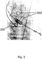
- Figure 3 shows an example of a fluoroscopy image showing on the one hand a distal end portion of a device/catheter 200, here in particular a collapsed stent-based heart valve on a catheter, and on the other hand calcifications 500 which may be used as anatomical landmarks in a method as illustrated in figure 1 .
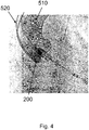
- Figure 4 shows an example of an angiography image including a darkened area 510 with a contrast agent in the ascending aorta. Based on such an angiography image, a roadmap 520 maybe generated as outlines of the darkened area 510.
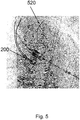
- Figure 5 shows an example of a fluoroscopic image together with a roadmap as generated in step S1 of the above described method.
- a computer program may be stored/distributed on a suitable medium such as an optical storage medium or a solid-state medium supplied together with or as a part of another hardware, but may also be distributed in other forms, such as via the internet or other wired or wireless telecommunication systems. Any reference signs in the claims should not be construed as limiting the scope.
Landscapes
- Health & Medical Sciences (AREA)
- Engineering & Computer Science (AREA)
- Life Sciences & Earth Sciences (AREA)
- Medical Informatics (AREA)
- Physics & Mathematics (AREA)
- General Health & Medical Sciences (AREA)
- Surgery (AREA)
- Nuclear Medicine, Radiotherapy & Molecular Imaging (AREA)
- Veterinary Medicine (AREA)
- Public Health (AREA)
- Radiology & Medical Imaging (AREA)
- Biomedical Technology (AREA)
- Heart & Thoracic Surgery (AREA)
- Molecular Biology (AREA)
- Animal Behavior & Ethology (AREA)
- Biophysics (AREA)
- Optics & Photonics (AREA)
- Pathology (AREA)
- High Energy & Nuclear Physics (AREA)
- Computer Vision & Pattern Recognition (AREA)
- General Physics & Mathematics (AREA)
- Theoretical Computer Science (AREA)
- Dentistry (AREA)
- Vascular Medicine (AREA)
- Multimedia (AREA)
- Oral & Maxillofacial Surgery (AREA)
- Human Computer Interaction (AREA)
- Robotics (AREA)
- Quality & Reliability (AREA)
- Apparatus For Radiation Diagnosis (AREA)
Claims (14)
- Procédé de détection automatique d'un événement dans lequel un dispositif (200) quitte une position stable par rapport à une anatomie et au sein de celle-ci, le procédé comprenant les étapes consistant à :recevoir une séquence d'images fluoroscopiques,détecter un dispositif (200) dans au moins deux des images fluoroscopiques,déterminer un champ de déplacement du dispositif détecté dans la séquence d'images fluoroscopiques,générer une séquence d'images intégrées en intégrant la séquence d'images fluoroscopiques en prenant en considération le champ de déplacement,caractérisé parla détermination d'une métrique de saillance basée sur les images intégrées,l'identification d'un point de repère (500) dans les images intégrées sur la base de la métrique de saillance.
- Procédé selon la revendication 1, comprenant l'étape de détermination quant au déplacement du point de repère (500) par rapport au dispositif (200) sur la base d'une variation de la métrique de saillance.
- Procédé selon l'une quelconque des revendications 1 et 2, dans lequel la séquence d'images fluoroscopiques comprend une première image fluoroscopique et une seconde image fluoroscopique, dans lequel la détermination d'un champ de déplacement comprend une détermination d'un déplacement du dispositif (200) entre une position détectée dans la première image fluoroscopique et une position détectée dans la seconde image fluoroscopique, et dans lequel le déplacement est pris en considération pour intégrer la pluralité d'images fluoroscopiques.
- Procédé selon l'une quelconque des revendications 1 à 3, dans lequel l'intégration de la séquence d'images fluoroscopiques est une intégration temporelle.
- Procédé selon l'une quelconque des revendications 1 à 4, dans lequel le point de repère (500) dans une image intégrée est déterminé sur la base de la hauteur de valeurs de pixels.
- Procédé selon l'une quelconque des revendications 1 à 5, dans lequel la métrique de saillance varie lorsque les valeurs de pixels varient dans la séquence d'images intégrées.
- Procédé selon l'une quelconque des revendications 1 à 6, comprenant en outre l'étape de visualisation d'au moins une image fluoroscopique dans la séquence d'images fluoroscopiques conjointement avec une feuille de route (520) sous la forme d'un recouvrement de la feuille de route sur la au moins une image fluoroscopique.
- Procédé selon la revendication 7, comprenant en outre l'étape visant à masquer la feuille de route (520) lorsqu'un déplacement du point de repère (500) par rapport au dispositif (200) est déterminé.
- Procédé selon l'une quelconque des revendications 1 à 8, dans lequel le point de repère (500) comprend une calcification dans un système vasculaire.
- Procédé selon l'une quelconque des revendications 1 à 9, dans lequel le point de repère comprend un élément déjà implanté.
- Système de détection automatique d'un événement dans lequel un dispositif (200) quitte une position stable par rapport à une anatomie et au sein de celle-ci, comprenant :un dispositif (400) configuré pour générer des images fluoroscopiques (100, 400) etun dispositif de traitement (600) configuré pour traiter les images fluoroscopiques conformément au procédé de l'une quelconque des revendications précédentes.
- Système selon la revendication 11, comprenant en outre un moniteur (610) pour afficher des images.
- Système selon l'une quelconque des revendications 11 et 12, comprenant en outre une base de données pour fournir une feuille de route.
- Programme informatique pour la détection automatique d'un événement dans lequel un dispositif quitte une position stable par rapport à une anatomie et au sein de celle-ci et qui, lorsqu'il est exécuté sur le dispositif de traitement du système selon la revendication 10, amène le système à effectuer le procédé selon la revendication 1.
Applications Claiming Priority (2)
| Application Number | Priority Date | Filing Date | Title |
|---|---|---|---|
| EP15305383 | 2015-03-16 | ||
| PCT/EP2016/054345 WO2016146380A1 (fr) | 2015-03-16 | 2016-03-02 | Détection automatique de mouvement |
Publications (2)
| Publication Number | Publication Date |
|---|---|
| EP3270786A1 EP3270786A1 (fr) | 2018-01-24 |
| EP3270786B1 true EP3270786B1 (fr) | 2018-12-19 |
Family
ID=52686305
Family Applications (1)
| Application Number | Title | Priority Date | Filing Date |
|---|---|---|---|
| EP16707718.9A Active EP3270786B1 (fr) | 2015-03-16 | 2016-03-02 | Détection de mouvement automatique |
Country Status (5)
| Country | Link |
|---|---|
| US (1) | US10869642B2 (fr) |
| EP (1) | EP3270786B1 (fr) |
| JP (2) | JP6636535B2 (fr) |
| CN (1) | CN107347249B (fr) |
| WO (1) | WO2016146380A1 (fr) |
Families Citing this family (6)
| Publication number | Priority date | Publication date | Assignee | Title |
|---|---|---|---|---|
| EP3270786B1 (fr) * | 2015-03-16 | 2018-12-19 | Koninklijke Philips N.V. | Détection de mouvement automatique |
| CN108605095B (zh) | 2016-02-26 | 2021-04-09 | 富士胶片株式会社 | 图像处理装置、摄像装置以及图像处理方法 |
| WO2019019048A1 (fr) * | 2017-07-26 | 2019-01-31 | Shenzhen Xpectvision Technology Co., Ltd. | Système d'imagerie radiologique et méthode de suivi d'image radiologique |
| CN107874760B (zh) * | 2017-09-27 | 2020-12-25 | 中国科学院深圳先进技术研究院 | 一种医学影像中的导丝追踪方法、装置、设备及存储介质 |
| EP4623404A1 (fr) * | 2022-11-22 | 2025-10-01 | Dolby Laboratories Licensing Corporation | Réglage adaptatif de la luminosité d'un visage pour des images et une vidéo |
| EP4530974A1 (fr) * | 2023-09-27 | 2025-04-02 | Koninklijke Philips N.V. | Visualisation de vaisseau occlus |
Family Cites Families (30)
| Publication number | Priority date | Publication date | Assignee | Title |
|---|---|---|---|---|
| JP2792133B2 (ja) * | 1989-08-30 | 1998-08-27 | 株式会社島津製作所 | 画像処理装置 |
| US5253169A (en) * | 1991-11-29 | 1993-10-12 | General Electric Company | Method and apparatus for reducing x-ray dosage during fluoroscopic examinations |
| US5274551A (en) * | 1991-11-29 | 1993-12-28 | General Electric Company | Method and apparatus for real-time navigation assist in interventional radiological procedures |
| US6320976B1 (en) * | 1999-04-01 | 2001-11-20 | Siemens Corporate Research, Inc. | Computer-assisted diagnosis method and system for automatically determining diagnostic saliency of digital images |
| ATE397902T1 (de) * | 2001-11-30 | 2008-07-15 | Koninkl Philips Electronics Nv | Bildverarbeitungsverfahren und system zum hervorheben von strukturen in verrauschten bildern |
| DE10247299A1 (de) | 2002-10-10 | 2004-04-22 | Philips Intellectual Property & Standards Gmbh | Bildverarbeitungseinheit und Verfahren für die Zuordnung von gespeicherten zu aktuellen Aufnahmen |
| US7907989B2 (en) | 2003-06-16 | 2011-03-15 | Koninklijke Philips Electronics N.V. | Imaging system for interventional radiology |
| DE102004004604B4 (de) * | 2004-01-29 | 2016-12-29 | Siemens Healthcare Gmbh | Verfahren und Bildgebungssystem zur Kompensation von Patientenbewegungen bei Serienaufnahmen in der medizinischen Bildgebung |
| KR20080043774A (ko) * | 2005-08-09 | 2008-05-19 | 코닌클리케 필립스 일렉트로닉스 엔.브이. | 블라인드 디콘볼루션으로 노이즈 이미지에서의 구조를공간적으로 향상시키는 시스템 및 방법 |
| US7826884B2 (en) * | 2006-07-31 | 2010-11-02 | Siemens Medical Solutions Usa, Inc. | Live fluoroscopic roadmapping including targeted automatic pixel shift for misregistration correction |
| US7907217B2 (en) * | 2006-10-31 | 2011-03-15 | Siemens Medical Solutions Usa, Inc. | Systems and methods of subtraction angiography utilizing motion prediction |
| US8111895B2 (en) * | 2006-12-06 | 2012-02-07 | Siemens Medical Solutions Usa, Inc. | Locally adaptive image enhancement for digital subtraction X-ray imaging |
| US7609814B2 (en) * | 2008-01-15 | 2009-10-27 | Siemens Medical Solutions Usa, Inc. | Adaptive medical image and mask data processing system |
| TWI535267B (zh) * | 2008-04-25 | 2016-05-21 | 湯姆生特許公司 | 影像序列的圖像之圖像部位寫碼方法及所用寫碼器和解碼器 |
| JP5523791B2 (ja) * | 2008-10-27 | 2014-06-18 | 株式会社東芝 | X線診断装置および画像処理装置 |
| JP2010115429A (ja) * | 2008-11-14 | 2010-05-27 | Toshiba Corp | X線診断装置および画像処理装置 |
| RU2535608C2 (ru) * | 2009-09-29 | 2014-12-20 | Конинклейке Филипс Электроникс Н.В. | Совмещение в реальном времени для лечения сосудов |
| JP5965840B2 (ja) * | 2009-09-29 | 2016-08-10 | コーニンクレッカ フィリップス エヌ ヴェKoninklijke Philips N.V. | 血管ロードマッピング |
| US9189851B2 (en) | 2010-01-07 | 2015-11-17 | Siemens Aktiengesellschaft | Method of motion compensation for trans-catheter aortic valve implantation |
| US8565859B2 (en) * | 2010-06-29 | 2013-10-22 | Siemens Aktiengesellschaft | Method and system for image based device tracking for co-registration of angiography and intravascular ultrasound images |
| US8712177B2 (en) * | 2011-01-25 | 2014-04-29 | Siemens Aktiengesellschaft | Motion compensated overlay |
| WO2012123850A1 (fr) * | 2011-03-15 | 2012-09-20 | Koninklijke Philips Electronics N.V. | Dispositif d'imagerie médicale pour fournir un support de représentation d'image lors du positionnement d'un dispositif d'intervention |
| US8600538B2 (en) * | 2011-04-11 | 2013-12-03 | Disney Enterprises, Inc. | System and method for producing three-dimensional multi-layer objects from digital models |
| US9186087B2 (en) | 2011-04-13 | 2015-11-17 | Siemens Aktiengesellschaft | Combined cardiac and respiratory motion compensation for atrial fibrillation ablation procedures |
| US8891009B2 (en) * | 2011-08-29 | 2014-11-18 | Futurewei Technologies, Inc. | System and method for retargeting video sequences |
| WO2013165565A1 (fr) * | 2012-04-30 | 2013-11-07 | Nikon Corporation | Procédé de détection de sujet principal dans une image |
| US9082158B2 (en) * | 2012-09-19 | 2015-07-14 | Siemens Aktiengesellschaft | Method and system for real time stent enhancement on live 2D fluoroscopic scene |
| US9259200B2 (en) * | 2012-10-18 | 2016-02-16 | Siemens Aktiengesellschaft | Method and system for obtaining a sequence of x-ray images using a reduced dose of ionizing radiation |
| US9147255B1 (en) * | 2013-03-14 | 2015-09-29 | Hrl Laboratories, Llc | Rapid object detection by combining structural information from image segmentation with bio-inspired attentional mechanisms |
| EP3270786B1 (fr) * | 2015-03-16 | 2018-12-19 | Koninklijke Philips N.V. | Détection de mouvement automatique |
-
2016
- 2016-03-02 EP EP16707718.9A patent/EP3270786B1/fr active Active
- 2016-03-02 JP JP2017548943A patent/JP6636535B2/ja active Active
- 2016-03-02 WO PCT/EP2016/054345 patent/WO2016146380A1/fr not_active Ceased
- 2016-03-02 CN CN201680015961.7A patent/CN107347249B/zh active Active
- 2016-03-02 US US15/557,855 patent/US10869642B2/en active Active
-
2019
- 2019-04-26 JP JP2019085270A patent/JP6828083B2/ja not_active Expired - Fee Related
Non-Patent Citations (1)
| Title |
|---|
| None * |
Also Published As
| Publication number | Publication date |
|---|---|
| CN107347249B (zh) | 2021-10-01 |
| JP2019162451A (ja) | 2019-09-26 |
| US20180055462A1 (en) | 2018-03-01 |
| CN107347249A (zh) | 2017-11-14 |
| JP6636535B2 (ja) | 2020-01-29 |
| JP6828083B2 (ja) | 2021-02-10 |
| EP3270786A1 (fr) | 2018-01-24 |
| US10869642B2 (en) | 2020-12-22 |
| JP2018507758A (ja) | 2018-03-22 |
| WO2016146380A1 (fr) | 2016-09-22 |
Similar Documents
| Publication | Publication Date | Title |
|---|---|---|
| EP2482726B1 (fr) | Cartographie vasculaire | |
| US8255037B2 (en) | Cardiac roadmapping | |
| EP3270786B1 (fr) | Détection de mouvement automatique | |
| US9042628B2 (en) | 3D-originated cardiac roadmapping | |
| JP6581598B2 (ja) | カテーテルの特定の位置を決定するための装置 | |
| US8554308B2 (en) | Phase-free cardiac roadmapping | |
| US20100292565A1 (en) | Medical imaging medical device navigation from at least two 2d projections from different angles | |
| JP2019500185A (ja) | 放射線照射を低減された手術中の3次元視覚化 | |
| US10478140B2 (en) | Nearest available roadmap selection | |
| KR101703564B1 (ko) | 혈관 정보를 포함하는 의료 영상을 디스플레이하는 장치 및 방법 |
Legal Events
| Date | Code | Title | Description |
|---|---|---|---|
| STAA | Information on the status of an ep patent application or granted ep patent |
Free format text: STATUS: THE INTERNATIONAL PUBLICATION HAS BEEN MADE |
|
| PUAI | Public reference made under article 153(3) epc to a published international application that has entered the european phase |
Free format text: ORIGINAL CODE: 0009012 |
|
| STAA | Information on the status of an ep patent application or granted ep patent |
Free format text: STATUS: REQUEST FOR EXAMINATION WAS MADE |
|
| 17P | Request for examination filed |
Effective date: 20171016 |
|
| AK | Designated contracting states |
Kind code of ref document: A1 Designated state(s): AL AT BE BG CH CY CZ DE DK EE ES FI FR GB GR HR HU IE IS IT LI LT LU LV MC MK MT NL NO PL PT RO RS SE SI SK SM TR |
|
| AX | Request for extension of the european patent |
Extension state: BA ME |
|
| GRAP | Despatch of communication of intention to grant a patent |
Free format text: ORIGINAL CODE: EPIDOSNIGR1 |
|
| STAA | Information on the status of an ep patent application or granted ep patent |
Free format text: STATUS: GRANT OF PATENT IS INTENDED |
|
| RIC1 | Information provided on ipc code assigned before grant |
Ipc: A61B 6/12 20060101ALI20180418BHEP Ipc: A61B 6/00 20060101AFI20180418BHEP Ipc: G06T 7/246 20170101ALI20180418BHEP |
|
| DAV | Request for validation of the european patent (deleted) | ||
| DAX | Request for extension of the european patent (deleted) | ||
| INTG | Intention to grant announced |
Effective date: 20180518 |
|
| GRAJ | Information related to disapproval of communication of intention to grant by the applicant or resumption of examination proceedings by the epo deleted |
Free format text: ORIGINAL CODE: EPIDOSDIGR1 |
|
| STAA | Information on the status of an ep patent application or granted ep patent |
Free format text: STATUS: REQUEST FOR EXAMINATION WAS MADE |
|
| GRAP | Despatch of communication of intention to grant a patent |
Free format text: ORIGINAL CODE: EPIDOSNIGR1 |
|
| STAA | Information on the status of an ep patent application or granted ep patent |
Free format text: STATUS: GRANT OF PATENT IS INTENDED |
|
| INTG | Intention to grant announced |
Effective date: 20180705 |
|
| GRAS | Grant fee paid |
Free format text: ORIGINAL CODE: EPIDOSNIGR3 |
|
| GRAA | (expected) grant |
Free format text: ORIGINAL CODE: 0009210 |
|
| STAA | Information on the status of an ep patent application or granted ep patent |
Free format text: STATUS: THE PATENT HAS BEEN GRANTED |
|
| AK | Designated contracting states |
Kind code of ref document: B1 Designated state(s): AL AT BE BG CH CY CZ DE DK EE ES FI FR GB GR HR HU IE IS IT LI LT LU LV MC MK MT NL NO PL PT RO RS SE SI SK SM TR |
|
| REG | Reference to a national code |
Ref country code: GB Ref legal event code: FG4D |
|
| REG | Reference to a national code |
Ref country code: CH Ref legal event code: EP |
|
| REG | Reference to a national code |
Ref country code: IE Ref legal event code: FG4D |
|
| REG | Reference to a national code |
Ref country code: DE Ref legal event code: R096 Ref document number: 602016008460 Country of ref document: DE |
|
| REG | Reference to a national code |
Ref country code: AT Ref legal event code: REF Ref document number: 1077805 Country of ref document: AT Kind code of ref document: T Effective date: 20190115 |
|
| REG | Reference to a national code |
Ref country code: NL Ref legal event code: MP Effective date: 20181219 |
|
| PG25 | Lapsed in a contracting state [announced via postgrant information from national office to epo] |
Ref country code: LV Free format text: LAPSE BECAUSE OF FAILURE TO SUBMIT A TRANSLATION OF THE DESCRIPTION OR TO PAY THE FEE WITHIN THE PRESCRIBED TIME-LIMIT Effective date: 20181219 Ref country code: NO Free format text: LAPSE BECAUSE OF FAILURE TO SUBMIT A TRANSLATION OF THE DESCRIPTION OR TO PAY THE FEE WITHIN THE PRESCRIBED TIME-LIMIT Effective date: 20190319 Ref country code: FI Free format text: LAPSE BECAUSE OF FAILURE TO SUBMIT A TRANSLATION OF THE DESCRIPTION OR TO PAY THE FEE WITHIN THE PRESCRIBED TIME-LIMIT Effective date: 20181219 Ref country code: HR Free format text: LAPSE BECAUSE OF FAILURE TO SUBMIT A TRANSLATION OF THE DESCRIPTION OR TO PAY THE FEE WITHIN THE PRESCRIBED TIME-LIMIT Effective date: 20181219 Ref country code: LT Free format text: LAPSE BECAUSE OF FAILURE TO SUBMIT A TRANSLATION OF THE DESCRIPTION OR TO PAY THE FEE WITHIN THE PRESCRIBED TIME-LIMIT Effective date: 20181219 Ref country code: BG Free format text: LAPSE BECAUSE OF FAILURE TO SUBMIT A TRANSLATION OF THE DESCRIPTION OR TO PAY THE FEE WITHIN THE PRESCRIBED TIME-LIMIT Effective date: 20190319 |
|
| REG | Reference to a national code |
Ref country code: LT Ref legal event code: MG4D |
|
| REG | Reference to a national code |
Ref country code: AT Ref legal event code: MK05 Ref document number: 1077805 Country of ref document: AT Kind code of ref document: T Effective date: 20181219 |
|
| PG25 | Lapsed in a contracting state [announced via postgrant information from national office to epo] |
Ref country code: RS Free format text: LAPSE BECAUSE OF FAILURE TO SUBMIT A TRANSLATION OF THE DESCRIPTION OR TO PAY THE FEE WITHIN THE PRESCRIBED TIME-LIMIT Effective date: 20181219 Ref country code: SE Free format text: LAPSE BECAUSE OF FAILURE TO SUBMIT A TRANSLATION OF THE DESCRIPTION OR TO PAY THE FEE WITHIN THE PRESCRIBED TIME-LIMIT Effective date: 20181219 Ref country code: GR Free format text: LAPSE BECAUSE OF FAILURE TO SUBMIT A TRANSLATION OF THE DESCRIPTION OR TO PAY THE FEE WITHIN THE PRESCRIBED TIME-LIMIT Effective date: 20190320 Ref country code: AL Free format text: LAPSE BECAUSE OF FAILURE TO SUBMIT A TRANSLATION OF THE DESCRIPTION OR TO PAY THE FEE WITHIN THE PRESCRIBED TIME-LIMIT Effective date: 20181219 |
|
| PG25 | Lapsed in a contracting state [announced via postgrant information from national office to epo] |
Ref country code: NL Free format text: LAPSE BECAUSE OF FAILURE TO SUBMIT A TRANSLATION OF THE DESCRIPTION OR TO PAY THE FEE WITHIN THE PRESCRIBED TIME-LIMIT Effective date: 20181219 |
|
| PG25 | Lapsed in a contracting state [announced via postgrant information from national office to epo] |
Ref country code: ES Free format text: LAPSE BECAUSE OF FAILURE TO SUBMIT A TRANSLATION OF THE DESCRIPTION OR TO PAY THE FEE WITHIN THE PRESCRIBED TIME-LIMIT Effective date: 20181219 Ref country code: PL Free format text: LAPSE BECAUSE OF FAILURE TO SUBMIT A TRANSLATION OF THE DESCRIPTION OR TO PAY THE FEE WITHIN THE PRESCRIBED TIME-LIMIT Effective date: 20181219 Ref country code: CZ Free format text: LAPSE BECAUSE OF FAILURE TO SUBMIT A TRANSLATION OF THE DESCRIPTION OR TO PAY THE FEE WITHIN THE PRESCRIBED TIME-LIMIT Effective date: 20181219 Ref country code: PT Free format text: LAPSE BECAUSE OF FAILURE TO SUBMIT A TRANSLATION OF THE DESCRIPTION OR TO PAY THE FEE WITHIN THE PRESCRIBED TIME-LIMIT Effective date: 20190419 Ref country code: IT Free format text: LAPSE BECAUSE OF FAILURE TO SUBMIT A TRANSLATION OF THE DESCRIPTION OR TO PAY THE FEE WITHIN THE PRESCRIBED TIME-LIMIT Effective date: 20181219 |
|
| PG25 | Lapsed in a contracting state [announced via postgrant information from national office to epo] |
Ref country code: RO Free format text: LAPSE BECAUSE OF FAILURE TO SUBMIT A TRANSLATION OF THE DESCRIPTION OR TO PAY THE FEE WITHIN THE PRESCRIBED TIME-LIMIT Effective date: 20181219 Ref country code: SK Free format text: LAPSE BECAUSE OF FAILURE TO SUBMIT A TRANSLATION OF THE DESCRIPTION OR TO PAY THE FEE WITHIN THE PRESCRIBED TIME-LIMIT Effective date: 20181219 Ref country code: IS Free format text: LAPSE BECAUSE OF FAILURE TO SUBMIT A TRANSLATION OF THE DESCRIPTION OR TO PAY THE FEE WITHIN THE PRESCRIBED TIME-LIMIT Effective date: 20190419 Ref country code: SM Free format text: LAPSE BECAUSE OF FAILURE TO SUBMIT A TRANSLATION OF THE DESCRIPTION OR TO PAY THE FEE WITHIN THE PRESCRIBED TIME-LIMIT Effective date: 20181219 Ref country code: EE Free format text: LAPSE BECAUSE OF FAILURE TO SUBMIT A TRANSLATION OF THE DESCRIPTION OR TO PAY THE FEE WITHIN THE PRESCRIBED TIME-LIMIT Effective date: 20181219 |
|
| REG | Reference to a national code |
Ref country code: DE Ref legal event code: R097 Ref document number: 602016008460 Country of ref document: DE |
|
| PLBE | No opposition filed within time limit |
Free format text: ORIGINAL CODE: 0009261 |
|
| STAA | Information on the status of an ep patent application or granted ep patent |
Free format text: STATUS: NO OPPOSITION FILED WITHIN TIME LIMIT |
|
| PG25 | Lapsed in a contracting state [announced via postgrant information from national office to epo] |
Ref country code: MC Free format text: LAPSE BECAUSE OF FAILURE TO SUBMIT A TRANSLATION OF THE DESCRIPTION OR TO PAY THE FEE WITHIN THE PRESCRIBED TIME-LIMIT Effective date: 20181219 Ref country code: DK Free format text: LAPSE BECAUSE OF FAILURE TO SUBMIT A TRANSLATION OF THE DESCRIPTION OR TO PAY THE FEE WITHIN THE PRESCRIBED TIME-LIMIT Effective date: 20181219 Ref country code: AT Free format text: LAPSE BECAUSE OF FAILURE TO SUBMIT A TRANSLATION OF THE DESCRIPTION OR TO PAY THE FEE WITHIN THE PRESCRIBED TIME-LIMIT Effective date: 20181219 |
|
| REG | Reference to a national code |
Ref country code: CH Ref legal event code: PL |
|
| 26N | No opposition filed |
Effective date: 20190920 |
|
| PG25 | Lapsed in a contracting state [announced via postgrant information from national office to epo] |
Ref country code: LU Free format text: LAPSE BECAUSE OF NON-PAYMENT OF DUE FEES Effective date: 20190302 |
|
| REG | Reference to a national code |
Ref country code: BE Ref legal event code: MM Effective date: 20190331 |
|
| PG25 | Lapsed in a contracting state [announced via postgrant information from national office to epo] |
Ref country code: IE Free format text: LAPSE BECAUSE OF NON-PAYMENT OF DUE FEES Effective date: 20190302 Ref country code: CH Free format text: LAPSE BECAUSE OF NON-PAYMENT OF DUE FEES Effective date: 20190331 Ref country code: LI Free format text: LAPSE BECAUSE OF NON-PAYMENT OF DUE FEES Effective date: 20190331 |
|
| PG25 | Lapsed in a contracting state [announced via postgrant information from national office to epo] |
Ref country code: SI Free format text: LAPSE BECAUSE OF FAILURE TO SUBMIT A TRANSLATION OF THE DESCRIPTION OR TO PAY THE FEE WITHIN THE PRESCRIBED TIME-LIMIT Effective date: 20181219 Ref country code: BE Free format text: LAPSE BECAUSE OF NON-PAYMENT OF DUE FEES Effective date: 20190331 |
|
| PG25 | Lapsed in a contracting state [announced via postgrant information from national office to epo] |
Ref country code: TR Free format text: LAPSE BECAUSE OF FAILURE TO SUBMIT A TRANSLATION OF THE DESCRIPTION OR TO PAY THE FEE WITHIN THE PRESCRIBED TIME-LIMIT Effective date: 20181219 |
|
| PG25 | Lapsed in a contracting state [announced via postgrant information from national office to epo] |
Ref country code: MT Free format text: LAPSE BECAUSE OF NON-PAYMENT OF DUE FEES Effective date: 20190302 |
|
| GBPC | Gb: european patent ceased through non-payment of renewal fee |
Effective date: 20200302 |
|
| PG25 | Lapsed in a contracting state [announced via postgrant information from national office to epo] |
Ref country code: GB Free format text: LAPSE BECAUSE OF NON-PAYMENT OF DUE FEES Effective date: 20200302 |
|
| PG25 | Lapsed in a contracting state [announced via postgrant information from national office to epo] |
Ref country code: CY Free format text: LAPSE BECAUSE OF FAILURE TO SUBMIT A TRANSLATION OF THE DESCRIPTION OR TO PAY THE FEE WITHIN THE PRESCRIBED TIME-LIMIT Effective date: 20181219 |
|
| PG25 | Lapsed in a contracting state [announced via postgrant information from national office to epo] |
Ref country code: HU Free format text: LAPSE BECAUSE OF FAILURE TO SUBMIT A TRANSLATION OF THE DESCRIPTION OR TO PAY THE FEE WITHIN THE PRESCRIBED TIME-LIMIT; INVALID AB INITIO Effective date: 20160302 |
|
| PG25 | Lapsed in a contracting state [announced via postgrant information from national office to epo] |
Ref country code: MK Free format text: LAPSE BECAUSE OF FAILURE TO SUBMIT A TRANSLATION OF THE DESCRIPTION OR TO PAY THE FEE WITHIN THE PRESCRIBED TIME-LIMIT Effective date: 20181219 |
|
| PGFP | Annual fee paid to national office [announced via postgrant information from national office to epo] |
Ref country code: DE Payment date: 20260320 Year of fee payment: 11 |
|
| PGFP | Annual fee paid to national office [announced via postgrant information from national office to epo] |
Ref country code: FR Payment date: 20260323 Year of fee payment: 11 |