EP4530974A1 - Visualisation de vaisseau occlus - Google Patents
Visualisation de vaisseau occlus Download PDFInfo
- Publication number
- EP4530974A1 EP4530974A1 EP23306619.0A EP23306619A EP4530974A1 EP 4530974 A1 EP4530974 A1 EP 4530974A1 EP 23306619 A EP23306619 A EP 23306619A EP 4530974 A1 EP4530974 A1 EP 4530974A1
- Authority
- EP
- European Patent Office
- Prior art keywords
- vessel
- sequence
- images
- occlusion
- image
- Prior art date
- Legal status (The legal status is an assumption and is not a legal conclusion. Google has not performed a legal analysis and makes no representation as to the accuracy of the status listed.)
- Withdrawn
Links
Images

Classifications
-
- G—PHYSICS
- G06—COMPUTING OR CALCULATING; COUNTING
- G06T—IMAGE DATA PROCESSING OR GENERATION, IN GENERAL
- G06T5/00—Image enhancement or restoration
- G06T5/50—Image enhancement or restoration using two or more images, e.g. averaging or subtraction
-
- A—HUMAN NECESSITIES
- A61—MEDICAL OR VETERINARY SCIENCE; HYGIENE
- A61B—DIAGNOSIS; SURGERY; IDENTIFICATION
- A61B6/00—Apparatus or devices for radiation diagnosis; Apparatus or devices for radiation diagnosis combined with radiation therapy equipment
- A61B6/44—Constructional features of apparatus for radiation diagnosis
- A61B6/4429—Constructional features of apparatus for radiation diagnosis related to the mounting of source units and detector units
- A61B6/4435—Constructional features of apparatus for radiation diagnosis related to the mounting of source units and detector units the source unit and the detector unit being coupled by a rigid structure
- A61B6/4441—Constructional features of apparatus for radiation diagnosis related to the mounting of source units and detector units the source unit and the detector unit being coupled by a rigid structure the rigid structure being a C-arm or U-arm
-
- A—HUMAN NECESSITIES
- A61—MEDICAL OR VETERINARY SCIENCE; HYGIENE
- A61B—DIAGNOSIS; SURGERY; IDENTIFICATION
- A61B6/00—Apparatus or devices for radiation diagnosis; Apparatus or devices for radiation diagnosis combined with radiation therapy equipment
- A61B6/48—Diagnostic techniques
- A61B6/486—Diagnostic techniques involving generating temporal series of image data
- A61B6/487—Diagnostic techniques involving generating temporal series of image data involving fluoroscopy
-
- A—HUMAN NECESSITIES
- A61—MEDICAL OR VETERINARY SCIENCE; HYGIENE
- A61B—DIAGNOSIS; SURGERY; IDENTIFICATION
- A61B6/00—Apparatus or devices for radiation diagnosis; Apparatus or devices for radiation diagnosis combined with radiation therapy equipment
- A61B6/50—Apparatus or devices for radiation diagnosis; Apparatus or devices for radiation diagnosis combined with radiation therapy equipment specially adapted for specific body parts; specially adapted for specific clinical applications
- A61B6/503—Apparatus or devices for radiation diagnosis; Apparatus or devices for radiation diagnosis combined with radiation therapy equipment specially adapted for specific body parts; specially adapted for specific clinical applications for diagnosis of the heart
-
- A—HUMAN NECESSITIES
- A61—MEDICAL OR VETERINARY SCIENCE; HYGIENE
- A61B—DIAGNOSIS; SURGERY; IDENTIFICATION
- A61B6/00—Apparatus or devices for radiation diagnosis; Apparatus or devices for radiation diagnosis combined with radiation therapy equipment
- A61B6/50—Apparatus or devices for radiation diagnosis; Apparatus or devices for radiation diagnosis combined with radiation therapy equipment specially adapted for specific body parts; specially adapted for specific clinical applications
- A61B6/504—Apparatus or devices for radiation diagnosis; Apparatus or devices for radiation diagnosis combined with radiation therapy equipment specially adapted for specific body parts; specially adapted for specific clinical applications for diagnosis of blood vessels, e.g. by angiography
-
- A—HUMAN NECESSITIES
- A61—MEDICAL OR VETERINARY SCIENCE; HYGIENE
- A61B—DIAGNOSIS; SURGERY; IDENTIFICATION
- A61B6/00—Apparatus or devices for radiation diagnosis; Apparatus or devices for radiation diagnosis combined with radiation therapy equipment
- A61B6/52—Devices using data or image processing specially adapted for radiation diagnosis
- A61B6/5211—Devices using data or image processing specially adapted for radiation diagnosis involving processing of medical diagnostic data
- A61B6/5217—Devices using data or image processing specially adapted for radiation diagnosis involving processing of medical diagnostic data extracting a diagnostic or physiological parameter from medical diagnostic data
-
- G—PHYSICS
- G06—COMPUTING OR CALCULATING; COUNTING
- G06T—IMAGE DATA PROCESSING OR GENERATION, IN GENERAL
- G06T7/00—Image analysis
- G06T7/0002—Inspection of images, e.g. flaw detection
- G06T7/0012—Biomedical image inspection
- G06T7/0014—Biomedical image inspection using an image reference approach
- G06T7/0016—Biomedical image inspection using an image reference approach involving temporal comparison
-
- G—PHYSICS
- G06—COMPUTING OR CALCULATING; COUNTING
- G06T—IMAGE DATA PROCESSING OR GENERATION, IN GENERAL
- G06T2207/00—Indexing scheme for image analysis or image enhancement
- G06T2207/10—Image acquisition modality
- G06T2207/10116—X-ray image
- G06T2207/10121—Fluoroscopy
-
- G—PHYSICS
- G06—COMPUTING OR CALCULATING; COUNTING
- G06T—IMAGE DATA PROCESSING OR GENERATION, IN GENERAL
- G06T2207/00—Indexing scheme for image analysis or image enhancement
- G06T2207/30—Subject of image; Context of image processing
- G06T2207/30004—Biomedical image processing
- G06T2207/30101—Blood vessel; Artery; Vein; Vascular
Definitions
- the present disclosure relates to providing an image representation of an occluded vessel.
- a system, a computer-implemented method, and a computer program product, are disclosed.
- Occlusions can occur for various reasons, including as a result of the build-up of plaque, or the development of a clot, in the vessel. Occlusions can occur in blood vessels in various parts of the anatomy, including in the heart, the brain, the lung, the leg, and so forth.
- an occlusion is partial, and blood flow in the vessel is restricted, but not blocked.
- a partial occlusion of a coronary artery may result in the heart having to work harder in order to maintain blood flow.
- blood flow in a vessel may be completely blocked by an occlusion.
- a chronic total occlusion, or "CTO" is defined as a complete blockage of a blood vessel for a duration of greater than or equal to 3 months.
- a treatment procedure may be required.
- An example of such a treatment procedure is a balloon angioplasty procedure.
- a balloon angioplasty procedure has the effect of opening-up a vessel lumen, thereby restoring blood flow through the vessel.
- Various interventional devices may be used in such treatment procedures, including a guidewire, a (balloon) catheter, and so forth.
- a balloon angioplasty often includes the placement of a stent in the vessel, and which serves to maintain the vessel lumen in the opened-up state Medical investigations relating to occluded vessels are often performed using angiographic images. X-ray angiographic images, i.e.
- X-ray images that are acquired subsequent to the injection of a contrast agent into the vasculature are often used for this purpose.
- the contrast agent introduces a difference between the X-ray attenuation of blood, and surrounding tissue, thereby improving the contrast between the vessel lumen, and the surrounding tissue in the X-ray angiographic images.
- the limited amount, or in the case of a CTO, the absence, of blood, and consequently contrast agent in the occlusion itself results in poor visibility of occlusions in X-ray angiographic images. Occluded vessels may therefore only appear in angiographic images as faint image features arising from the attenuation of vessel walls, calcifications, and any contrast agent that manages to pass along the vessel lumen.
- a system for providing an image representation of an occluded vessel comprises one or more processors configured to:
- occluded vessels are typically only poorly visible in angiographic images.
- angiographic images are mutually registered using motion vectors that are determined based on the motion of a detected portion of a vessel abutting the occlusion. Using the portion of the vessel abutting the occlusion to mutually-register the images ensures that the images are accurately registered in the vicinity of the occlusion. This portion of the vessel is also visible in angiographic images because blood reaches this portion of the vessel.
- the image intensities in the mutually-registered sequence of angiographic images are then processed in a region of interest adjoining the portion of the vessel to provide an image representation of the occluded vessel.
- the image intensities may be processed using techniques such as temporal integration, for example.
- the image representation may be referred to as an enhanced image representation of the occluded vessel since the visibility of the occluded vessel is enhanced as compared to in the sequence of angiographic images. Since this processing is based on the accurately co-registered images, faint image features of the occluded vessel arising from the attenuation of vessel walls, calcifications, and any contrast agent that manages to pass along the vessel lumen, are well-aligned in the region of interest in the mutually-registered images. This facilitates their processing so as to provide an accurate image representation of the occluded vessel.
- the occluded vessel is a coronary artery, i.e. a blood vessel located in the heart. It is, however, to be appreciated that the coronary artery, and the heart, serve only as examples of a location, and a type, of the occluded vessel.
- the occluded vessel may be any type of blood vessel, including an artery, or a vein, for example.
- the occluded vessel may be in any location in the anatomy, including in the heart, the brain, the lung, the leg, and so forth.
- the occlusion is a CTO. It is, however, to be appreciated that the occlusion may in general be any type of occlusion. For instance, the occlusion may alternatively be a partial occlusion.
- the computer-implemented methods disclosed herein may be provided as a non-transitory computer-readable storage medium including computer-readable instructions stored thereon, which, when executed by at least one processor, cause the at least one processor to perform the method.
- the computer-implemented methods may be implemented in a computer program product.
- the computer program product can be provided by dedicated hardware, or hardware capable of running the software in association with appropriate software.
- the functions of the method features can be provided by a single dedicated processor, or by a single shared processor, or by a plurality of individual processors, some of which can be shared.
- the functions of one or more of the method features may for instance be provided by processors that are shared within a networked processing architecture such as a client/server architecture, a peer-to-peer architecture, the Internet, or the Cloud.
- processor or “controller” should not be interpreted as exclusively referring to hardware capable of running software, and can implicitly include, but is not limited to, digital signal processor "DSP” hardware, read only memory “ROM” for storing software, random access memory “RAM”, a non-volatile storage device, and the like.
- DSP digital signal processor
- ROM read only memory
- RAM random access memory
- examples of the present disclosure can take the form of a computer program product accessible from a computer-usable storage medium, or a computer-readable storage medium, the computer program product providing program code for use by or in connection with a computer or any instruction execution system.
- a computer-usable storage medium or a computer readable storage medium can be any apparatus that can comprise, store, communicate, propagate, or transport a program for use by or in connection with an instruction execution system, apparatus, or device.
- the medium can be an electronic, magnetic, optical, electromagnetic, infrared, or a semiconductor system or device or propagation medium.
- Examples of computer-readable media include semiconductor or solid-state memories, magnetic tape, removable computer disks, random access memory "RAM”, read-only memory "ROM”, rigid magnetic disks and optical disks. Current examples of optical disks include compact disk-read only memory "CD-ROM”, compact disk-read/write "CD-R/W”, Blu-Ray TM and DVD.
- Suitable techniques may include machine learning techniques, as well as deep learning techniques such as neural networks.
- one or more neural networks may be trained in a supervised, or in some cases unsupervised, manner, to implement the operations that are performed by the one or more processors.
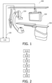
- Fig. 1 is a schematic diagram illustrating an example of a system 100 for providing an image representation of an occluded vessel, in accordance with some aspects of the present disclosure.
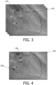
- Fig. 2 is a flowchart illustrating an example of a computer-implemented method of providing an image representation of an occluded vessel, in accordance with some aspects of the present disclosure. It is noted that operations that are described as being performed by the one or more processors 110 of the system 100 illustrated in Fig. 1 , may also be performed in the method illustrated in Fig. 2 . Likewise, operations that are described in relation to the method described with reference to Fig. 2 may also be performed by the one or more processors 110 of the system 100 illustrated in Fig. 1 .
- the system 100 for providing an image representation of an occluded vessel comprises one or more processors 110 configured to:
- occluded vessels are typically only poorly visible in angiographic images.
- angiographic images are mutually registered using motion vectors that are determined based on the motion of a detected portion of a vessel abutting the occlusion. Using the portion of the vessel abutting the occlusion to mutually-register the images ensures that the images are accurately registered in the vicinity of the occlusion. This portion of the vessel is also visible in angiographic images because blood reaches this portion of the vessel.
- the image intensities in the mutually-registered sequence of angiographic images are then processed in a region of interest adjoining the portion of the vessel to provide an image representation of the occluded vessel.
- the image intensities may be processed using techniques such as temporal integration, for example.
- the image representation may be referred to as an enhanced image representation of the occluded vessel since the visibility of the occluded vessel is enhanced as compared to in the sequence of angiographic images. Since this processing is based on the accurately co-registered images, faint image features of the occluded vessel arising from the attenuation of vessel walls, calcifications, and any contrast agent that manages to pass along the vessel lumen, are well-aligned in the region of interest in the mutually-registered images. This facilitates their processing so as to provide an accurate image representation of the occluded vessel.
- image data is received.
- the image data represents a sequence of angiographic images 120 comprising an occlusion 130 in a vessel 140.
- the sequence of angiographic images 120 that is received in the operation S110 may be generated by various types of imaging systems. These include two-dimensional imaging systems such as projection X-ray imaging systems, and also volumetric imaging systems such as computed tomography "CT” imaging systems and magnetic resonance imaging "MRI” systems. In examples in which the sequence of angiographic images 120 is generated by a projection X-ray imaging system, or by a CT imaging system, the imaging system may be a spectral X-ray projection imaging system, or a spectral CT imaging system, respectively. Such imaging systems generate X-ray attenuation data representing X-ray attenuation within multiple different energy intervals. The X-ray attenuation data generated by such imaging systems may be processed, e.g.
- X-ray attenuation data generated by spectral X-ray projection imaging systems, or by spectral CT imaging systems may be processed to provide angiographic images with improved specificity to materials such as contrast agent, tissue, bone, and so forth.
- the sequence of angiographic images 120 is generated subsequent to the injection of a contrast agent into the vasculature of a subject.
- the contrast agent serves to improve the contrast between blood and surrounding tissue in the angiographic images 120.
- the angiographic images 120 may be referred-to as contrast-enhanced angiographic images.
- Sequences of contrast-enhanced angiographic images may be generated by a projection X-ray imaging system, or by a CT imaging system, or by an MRI system.
- MRI angiographic images may alternatively be generated in the absence of a contrast agent, and are often referred-to as non-contrast-enhanced MR angiography "NC-MRA" images.
- the images in the sequence of angiographic images 120 are generated instantaneously before being received by the one or more processors 110.
- the sequence of angiographic images 120 may be a live sequence of angiographic images 120.
- the sequence of angiographic images 120 may have been generated some seconds, minutes, hours, or even days, or a longer period, before being received by the one or more processors 110.
- the sequence of angiographic images 120 may have been generated prior to performing a medical procedure on the anatomical region.
- the sequence of angiographic images 120 may be referred-to as a pre-procedural sequence of angiographic images 120.
- the sequence of angiographic images 120 may be received from various sources in the operation S110, including from a medical imaging system such as one of the imaging systems described above.
- the sequence of angiographic images 120 may be received from another source, such as from a computer readable storage medium, or from the internet, or from the Cloud, and so forth.
- the sequence of angiographic images 120 may be received via any form of data communication, including wired and wireless communication.
- wired communication when wired communication is used, the communication may take place via an electrical or optical cable, and when wireless communication is used, the communication may for example take place via RF or infrared signals.
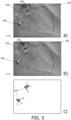
- Fig. 3 illustrates an example of a sequence of angiographic images 120 comprising an occlusion 130 in a vessel 140, in accordance with some aspects of the present disclosure.
- the angiographic images 120 illustrated in Fig. 3 represent the vasculature of the heart.
- the angiographic images 120 illustrated in Fig. 3 are contrast-enhanced X-ray angiographic images that have been generated subsequent to the injection of a contrast agent into a subject.
- the contrast-enhanced X-ray angiographic images illustrated in Fig. 3 may be generated using a projection X-ray imaging system, such as the C-arm-based projection X-ray imaging system 210 illustrated in Fig. 1 .
- a projection X-ray imaging system such as the C-arm-based projection X-ray imaging system 210 illustrated in Fig. 1 .
- the vessel 140 includes an occlusion 130.
- the occlusion 130 extends between the points labelled A, and A'.
- the occlusion completely blocks the flow of blood, and the occlusion 130 is a CTO.
- the occlusion 130 is poorly visible in the angiographic images 120.
- a portion 140 p , 140 d of the vessel abutting the occlusion 130 is detected in the sequence of angiographic images 120.
- a portion of the vessel abutting the occlusion is visible in the angiographic images because blood reaches this portion of the vessel.
- This portion of the vessel 140 may be referred-to as a "stump" of the vessel because beyond this portion of the vessel, the vessel appears to be truncated in the angiographic images 120.
- proximal and distal in this context refer to relative positions with respect to the direction of conventional blood flow in the vessel.
- a single, i.e. a proximal or a distal, or alternatively both, i.e. a proximal and a distal, portion of the vessel 140 abutting the occlusion 130 may be detected in the operation S120.
- the portion of the vessel that is detected in the operation S120 may be a point, such as a distal, or proximal, end of the vessel abutting the occlusion 130. Alternatively it may be a longer portion of the vessel, such as a segment of the vessel.
- motion vectors 150 that represent a motion of the portion 140 p , 140 d of the vessel, are extracted from the sequence of angiographic images 120, by determining changes in the position of the detected portion 140 p , 140 d of the vessel in the angiographic images.
- the motion vectors 150 may for example represent a motion of the portion 140 p , 140 d of the vessel with respect to a reference image in the sequence.
- the detection of the distal portion 140 d of the vessel, and the extraction of motion vectors representing a motion of the distal portion 140 d of the vessel may be performed in the same manner as described above for the proximal portion 140 p .
- Using both the proximal and the distal portion of the vessel in accordance with this example may serve to improve the reliability of the image representation of the vessel because the path of the vessel is constrained at both ends by the detected portions of the vessel.
- Improved guidance is provided to a physician by each of: displaying the image representation 160 and the live sequence of fluoroscopic images as an overlay image; displaying the image representation 160 and the live sequence of fluoroscopic images adjacent one another; displaying a path of the occluded vessel 140 in the live sequence of fluoroscopic images; and displaying one or more features of the occluded vessel 140 in the live sequence of fluoroscopic images.
- this additional guidance is provided without the need for additional contrast agent injections. Thus, it also reduces the health risks associated with contrast agent usage.
- the live sequence of fluoroscopic images comprises an interventional device in the vessel 140.
- the one or more processors 110 are configured to:
- the motion of the portion of the interventional device is used in combination with the motion of the portion 140 p , 140 d of the vessel abutting the occlusion 130, as determined from the angiographic images, to mutually register the angiographic images.
- the portion of the interventional device that is detected in this example may for instance be a radiopaque tip of the interventional device, or a radiopaque marker attached to the interventional device, a portion of a guidewire formed from a radiopaque material, and so forth.
- the radiopacity of such interventional device features facilitates their detection in the fluoroscopic images in the absence of a contrast agent.
- a further benefit of using the interventional device to perform this registration is that as the interventional device advances into the occlusion in the fluoroscopic images, it follows the path of the occlusion. Consequently, the motion of the interventional device, as determined from the fluoroscopic images, provides reliable information on the motion of the occluded vessel, and also the shape, of the occluded vessel, within the occlusion itself. Thus, it serves to improve the reliability of the image representation 160 of the occluded vessel.
- a volumetric angiographic image comprising the vessel 140 is used to estimate a shape of the vessel 140 in the sequence of angiographic images 120.
- the image data that is received in the operation S110 comprises projection image data and the sequence of angiographic images comprises a sequence of projected angiographic images, and the one or more processors 110 are also configured to:
- the volumetric angiographic image is used to estimate a shape of the vessel 140 in the angiographic images 120
- the estimated shape of the vessel 140 in the angiographic images 120 is used to detect S120 the portion 140 p , 140 d of the vessel abutting the occlusion 130 in the sequence of angiographic images 120..
- This may improve the reliability of the detection of the portion 140 p , 140 d of the vessel, or it may reduce the time taken to detect the portion 140 p , 140 d of the vessel because the volumetric angiographic image, in contrast to the projection angiographic images that are received in the operation S110, includes additional information on the shape and movement of the portion of the vessel 140. Consequently, it improves the reliability of the image representation 160 of the occluded vessel, and also reduces the time taken to generate the image representation 160.
- the shape of the vessel 140 in the sequence of angiographic images may be estimated by identifying the vessel 140 in the volumetric angiographic image, and subsequently registering the volumetric angiographic image, including the identified vessel, to the sequence of projection angiographic images that are acquired in the operation S110.
- the portion 140 p , 140 d of the vessel abutting the occlusion 130 in the sequence of angiographic images 120 may be determined by finding a (minimal) path in the angiographic images path that is constrained by the projected estimated shape of the vessel.
- the vessel 140 may be identified in the volumetric angiographic image using segmentation techniques such as model-based segmentation, semantic segmentation, and so forth.
- the registration may be performed by projecting the volumetric angiographic image, including the identified vessel, so as to provide a synthetic projection image from the same perspective of a projection X-ray imaging system as the sequence of projection angiographic images, and then (elastically) registering the synthetic projection image to the projection angiographic images.
- This provides synthetic projection images, which include the identified vessel 140, and which correspond to the projection angiographic images, and consequently it facilitates the identification of the identified vessel in the projection angiographic images.
- the volumetric angiographic image may be a (pre-procedural) CT image or a (pre-procedural) MRI image, for example.
- the volumetric angiographic image may be referred-to as a coronary computed tomography angiography "CCTA" image if the vessel is in the heart.
- CCTA coronary computed tomography angiography
- the motion vectors may be extracted in the manner described above.
- the one or more processors 110 are configured to evaluate an accuracy parameter for the image representation 160 and to output the value of the accuracy parameter.
- the value of the accuracy parameter may be calculated based on factors such as a sharpness of the image representation 160 within the region of interest, or based on a confidence measure for the operation of detecting (S120) the portion of the vessel abutting the occlusion.
- the value of the accuracy parameter may be calculated using the motion vectors. For instance, if the motion field has an excessive magnitude, or if the motion field is indicative of a high degree of bending, a relatively lower accuracy parameter may be provided. Providing the value of the accuracy parameter allows a physician to assess the extent to which the image representation 160 can be relied upon.
- an estimated extension to the portion of the vessel 140 p , 140 d is provided.
- the one or more processors 110 are configured to:
- the value of the accuracy parameter may be indicated in the image representation.
- the region of interest adjoining the portion of the vessel, or the predicted extension to the vessel, or the estimated extension to the vessel may be provided with a color that corresponds to the value of the accuracy parameter. This indicates to a physician the extent to which the image representation 160 can be relied upon.
- an additional benefit is provided if the portion of the interventional device is in contact with the occlusion because in this arrangement the detected portion of the interventional device provides an accurate indication of the vessel motion close to the occlusion, i.e. at a point in the vessel in which the visibility of the portion 140 p , 140 d of the vessel abutting the occlusion 130 starts to diminish as a result of the occlusion.
- a computer-implemented method of providing an image representation of an occluded vessel includes:
- a computer program product comprises instructions which when executed by one or more processors 110, cause the one or more processors to carry out a method of providing an image representation of an occluded vessel.
- the method includes:
Landscapes
- Health & Medical Sciences (AREA)
- Engineering & Computer Science (AREA)
- Life Sciences & Earth Sciences (AREA)
- Medical Informatics (AREA)
- Physics & Mathematics (AREA)
- General Health & Medical Sciences (AREA)
- Radiology & Medical Imaging (AREA)
- Nuclear Medicine, Radiotherapy & Molecular Imaging (AREA)
- Heart & Thoracic Surgery (AREA)
- Public Health (AREA)
- Optics & Photonics (AREA)
- Pathology (AREA)
- Biophysics (AREA)
- Biomedical Technology (AREA)
- High Energy & Nuclear Physics (AREA)
- Molecular Biology (AREA)
- Surgery (AREA)
- Animal Behavior & Ethology (AREA)
- Veterinary Medicine (AREA)
- Computer Vision & Pattern Recognition (AREA)
- Dentistry (AREA)
- Oral & Maxillofacial Surgery (AREA)
- General Physics & Mathematics (AREA)
- Theoretical Computer Science (AREA)
- Physiology (AREA)
- Cardiology (AREA)
- Quality & Reliability (AREA)
- Vascular Medicine (AREA)
- Apparatus For Radiation Diagnosis (AREA)
Priority Applications (3)
| Application Number | Priority Date | Filing Date | Title |
|---|---|---|---|
| EP23306619.0A EP4530974A1 (fr) | 2023-09-27 | 2023-09-27 | Visualisation de vaisseau occlus |
| CN202480062432.7A CN121970082A (zh) | 2023-09-27 | 2024-09-18 | 堵塞血管可视化 |
| PCT/EP2024/076006 WO2025067965A1 (fr) | 2023-09-27 | 2024-09-18 | Visualisation d'un vaisseau obstrué |
Applications Claiming Priority (1)
| Application Number | Priority Date | Filing Date | Title |
|---|---|---|---|
| EP23306619.0A EP4530974A1 (fr) | 2023-09-27 | 2023-09-27 | Visualisation de vaisseau occlus |
Publications (1)
| Publication Number | Publication Date |
|---|---|
| EP4530974A1 true EP4530974A1 (fr) | 2025-04-02 |
Family
ID=88315834
Family Applications (1)
| Application Number | Title | Priority Date | Filing Date |
|---|---|---|---|
| EP23306619.0A Withdrawn EP4530974A1 (fr) | 2023-09-27 | 2023-09-27 | Visualisation de vaisseau occlus |
Country Status (3)
| Country | Link |
|---|---|
| EP (1) | EP4530974A1 (fr) |
| CN (1) | CN121970082A (fr) |
| WO (1) | WO2025067965A1 (fr) |
Citations (5)
| Publication number | Priority date | Publication date | Assignee | Title |
|---|---|---|---|---|
| US20060058643A1 (en) * | 2002-11-13 | 2006-03-16 | Koninklijke Philips Electronics, N.V. | Medical viewing system and method for detecting boundary structures |
| WO2008104921A2 (fr) | 2007-02-28 | 2008-09-04 | Koninklijke Philips Electronics N.V. | Cartographie cardiaque indépendante des phases |
| US20090169080A1 (en) * | 2005-08-09 | 2009-07-02 | Koninklijke Philips Electronics, N.V. | System and method for spatially enhancing structures in noisy images with blind de-convolution |
| US20180055462A1 (en) * | 2015-03-16 | 2018-03-01 | Koninklijke Philips N.V. | Automatic movement detection |
| JP2020513923A (ja) * | 2017-01-05 | 2020-05-21 | コーニンクレッカ フィリップス エヌ ヴェKoninklijke Philips N.V. | 閉塞を有する血管構造の経路の視覚化 |
-
2023
- 2023-09-27 EP EP23306619.0A patent/EP4530974A1/fr not_active Withdrawn
-
2024
- 2024-09-18 CN CN202480062432.7A patent/CN121970082A/zh active Pending
- 2024-09-18 WO PCT/EP2024/076006 patent/WO2025067965A1/fr active Pending
Patent Citations (5)
| Publication number | Priority date | Publication date | Assignee | Title |
|---|---|---|---|---|
| US20060058643A1 (en) * | 2002-11-13 | 2006-03-16 | Koninklijke Philips Electronics, N.V. | Medical viewing system and method for detecting boundary structures |
| US20090169080A1 (en) * | 2005-08-09 | 2009-07-02 | Koninklijke Philips Electronics, N.V. | System and method for spatially enhancing structures in noisy images with blind de-convolution |
| WO2008104921A2 (fr) | 2007-02-28 | 2008-09-04 | Koninklijke Philips Electronics N.V. | Cartographie cardiaque indépendante des phases |
| US20180055462A1 (en) * | 2015-03-16 | 2018-03-01 | Koninklijke Philips N.V. | Automatic movement detection |
| JP2020513923A (ja) * | 2017-01-05 | 2020-05-21 | コーニンクレッカ フィリップス エヌ ヴェKoninklijke Philips N.V. | 閉塞を有する血管構造の経路の視覚化 |
Non-Patent Citations (2)
| Title |
|---|
| BENMANSOUR, F ET AL.: "Fast object segmentation by growing minimal paths from a single point on 2D or 3D images", J MATH IMAGING VIS, vol. 33, 2009, pages 209 - 221, XP019679337, Retrieved from the Internet <URL:https://doi.org/l0.1007/s10851-008-0131-0> |
| ISENSEE, F ET AL., AUTOMATED DESIGN OF DEEP LEARNING METHODS FOR BIOMEDICAL IMAGE SEGMENTATION, pages 1 - 55, Retrieved from the Internet <URL:https://arxiv.org/pdf/1904.08128.pdf> |
Also Published As
| Publication number | Publication date |
|---|---|
| WO2025067965A1 (fr) | 2025-04-03 |
| CN121970082A (zh) | 2026-05-01 |
Similar Documents
| Publication | Publication Date | Title |
|---|---|---|
| US7853061B2 (en) | System and method to improve visibility of an object in an imaged subject | |
| US10362943B2 (en) | Dynamic overlay of anatomy from angiography to fluoroscopy | |
| CN101836234A (zh) | 灰度光栅图像中的目标的探测和暗化方法 | |
| US12551296B2 (en) | Estimating the endoluminal path of an endoluminal device along a lumen | |
| JP6232147B2 (ja) | X線データにおいてteeプローブのイメージングを修正するための装置 | |
| EP2940657A1 (fr) | Régression pour une modélisation périodique en fonction de la phase en angiographie | |
| EP4468238A1 (fr) | Localisation de sténose | |
| CN113947205A (zh) | 神经网络模型训练方法、计算机可读存储介质和设备 | |
| US20240320842A1 (en) | Providing a result dataset | |
| EP4530974A1 (fr) | Visualisation de vaisseau occlus | |
| US12588881B2 (en) | Providing a result data set | |
| Bredno et al. | Algorithmic solutions for live device-to-vessel match | |
| EP4542489A1 (fr) | Fourniture d'une représentation d'image d'une région vasculaire | |
| EP4666958A1 (fr) | Détermination de géométrie de section transversale de récipient | |
| EP4623833A1 (fr) | Fourniture de rétroaction pendant une angioplastie à ballonnet | |
| Ohnishi et al. | Respiratory-synchronized digital subtraction angiography based on a respiratory phase matching method | |
| EP4524890A1 (fr) | Fourniture d'une image de projection d'une région vasculaire | |
| US20250384558A1 (en) | Providing a classified data set | |
| EP4585159A1 (fr) | Représentation d'image d'une région vasculaire à partir de données d'image volumétriques et angiographiques | |
| WO2025061493A1 (fr) | Fourniture d'une image de projection d'une région vasculaire | |
| Robert et al. | A lesion stabilization method for coronary angiography | |
| CN118591345A (zh) | 用于交替地显示图形表示的方法和系统 | |
| CN118717157A (zh) | 对图形显示的调整 | |
| WO2023100838A1 (fr) | Programme informatique, dispositif de traitement d'informations, procédé de traitement d'informations et procédé de génération de modèle d'apprentissage |
Legal Events
| Date | Code | Title | Description |
|---|---|---|---|
| PUAI | Public reference made under article 153(3) epc to a published international application that has entered the european phase |
Free format text: ORIGINAL CODE: 0009012 |
|
| STAA | Information on the status of an ep patent application or granted ep patent |
Free format text: STATUS: THE APPLICATION HAS BEEN PUBLISHED |
|
| AK | Designated contracting states |
Kind code of ref document: A1 Designated state(s): AL AT BE BG CH CY CZ DE DK EE ES FI FR GB GR HR HU IE IS IT LI LT LU LV MC ME MK MT NL NO PL PT RO RS SE SI SK SM TR |
|
| STAA | Information on the status of an ep patent application or granted ep patent |
Free format text: STATUS: THE APPLICATION IS DEEMED TO BE WITHDRAWN |
|
| 18D | Application deemed to be withdrawn |
Effective date: 20251003 |