EP3272028B1 - Circuit frontal rf reconfigurable destiné à un système d'antenne à réflecteur alimenté à réseau multi-faisceau - Google Patents
Circuit frontal rf reconfigurable destiné à un système d'antenne à réflecteur alimenté à réseau multi-faisceau Download PDFInfo
- Publication number
- EP3272028B1 EP3272028B1 EP15711729.2A EP15711729A EP3272028B1 EP 3272028 B1 EP3272028 B1 EP 3272028B1 EP 15711729 A EP15711729 A EP 15711729A EP 3272028 B1 EP3272028 B1 EP 3272028B1
- Authority
- EP
- European Patent Office
- Prior art keywords
- hpa
- high power
- reconfigurable
- output
- llrbfn
- Prior art date
- Legal status (The legal status is an assumption and is not a legal conclusion. Google has not performed a legal analysis and makes no representation as to the accuracy of the status listed.)
- Active
Links
Images


Classifications
-
- H—ELECTRICITY
- H01—ELECTRIC ELEMENTS
- H01Q—ANTENNAS, i.e. RADIO AERIALS
- H01Q3/00—Arrangements for changing or varying the orientation or the shape of the directional pattern of the waves radiated from an antenna or antenna system
- H01Q3/26—Arrangements for changing or varying the orientation or the shape of the directional pattern of the waves radiated from an antenna or antenna system varying the relative phase or relative amplitude of energisation between two or more active radiating elements; varying the distribution of energy across a radiating aperture
- H01Q3/2664—Arrangements for changing or varying the orientation or the shape of the directional pattern of the waves radiated from an antenna or antenna system varying the relative phase or relative amplitude of energisation between two or more active radiating elements; varying the distribution of energy across a radiating aperture electrically moving the phase centre of a radiating element in the focal plane of a focussing device
-
- H—ELECTRICITY
- H01—ELECTRIC ELEMENTS
- H01Q—ANTENNAS, i.e. RADIO AERIALS
- H01Q1/00—Details of, or arrangements associated with, antennas
- H01Q1/27—Adaptation for use in or on movable bodies
- H01Q1/28—Adaptation for use in or on aircraft, missiles, satellites, or balloons
- H01Q1/288—Satellite antennas
-
- H—ELECTRICITY
- H01—ELECTRIC ELEMENTS
- H01Q—ANTENNAS, i.e. RADIO AERIALS
- H01Q19/00—Combinations of primary active antenna elements and units with secondary devices, e.g. with quasi-optical devices, for giving the antenna a desired directional characteristic
- H01Q19/10—Combinations of primary active antenna elements and units with secondary devices, e.g. with quasi-optical devices, for giving the antenna a desired directional characteristic using reflecting surfaces
- H01Q19/12—Combinations of primary active antenna elements and units with secondary devices, e.g. with quasi-optical devices, for giving the antenna a desired directional characteristic using reflecting surfaces wherein the surfaces are concave
- H01Q19/17—Combinations of primary active antenna elements and units with secondary devices, e.g. with quasi-optical devices, for giving the antenna a desired directional characteristic using reflecting surfaces wherein the surfaces are concave the primary radiating source comprising two or more radiating elements
-
- H—ELECTRICITY
- H01—ELECTRIC ELEMENTS
- H01Q—ANTENNAS, i.e. RADIO AERIALS
- H01Q25/00—Antennas or antenna systems providing at least two radiating patterns
- H01Q25/007—Antennas or antenna systems providing at least two radiating patterns using two or more primary active elements in the focal region of a focusing device
-
- H—ELECTRICITY
- H01—ELECTRIC ELEMENTS
- H01Q—ANTENNAS, i.e. RADIO AERIALS
- H01Q3/00—Arrangements for changing or varying the orientation or the shape of the directional pattern of the waves radiated from an antenna or antenna system
- H01Q3/26—Arrangements for changing or varying the orientation or the shape of the directional pattern of the waves radiated from an antenna or antenna system varying the relative phase or relative amplitude of energisation between two or more active radiating elements; varying the distribution of energy across a radiating aperture
- H01Q3/30—Arrangements for changing or varying the orientation or the shape of the directional pattern of the waves radiated from an antenna or antenna system varying the relative phase or relative amplitude of energisation between two or more active radiating elements; varying the distribution of energy across a radiating aperture varying the relative phase between the radiating elements of an array
- H01Q3/34—Arrangements for changing or varying the orientation or the shape of the directional pattern of the waves radiated from an antenna or antenna system varying the relative phase or relative amplitude of energisation between two or more active radiating elements; varying the distribution of energy across a radiating aperture varying the relative phase between the radiating elements of an array by electrical means
- H01Q3/40—Arrangements for changing or varying the orientation or the shape of the directional pattern of the waves radiated from an antenna or antenna system varying the relative phase or relative amplitude of energisation between two or more active radiating elements; varying the distribution of energy across a radiating aperture varying the relative phase between the radiating elements of an array by electrical means with phasing matrix
-
- H—ELECTRICITY
- H04—ELECTRIC COMMUNICATION TECHNIQUE
- H04B—TRANSMISSION
- H04B7/00—Radio transmission systems, i.e. using radiation field
- H04B7/14—Relay systems
- H04B7/15—Active relay systems
- H04B7/185—Space-based or airborne stations; Stations for satellite systems
- H04B7/1851—Systems using a satellite or space-based relay
- H04B7/18515—Transmission equipment in satellites or space-based relays
-
- H—ELECTRICITY
- H04—ELECTRIC COMMUNICATION TECHNIQUE
- H04B—TRANSMISSION
- H04B7/00—Radio transmission systems, i.e. using radiation field
- H04B7/14—Relay systems
- H04B7/15—Active relay systems
- H04B7/204—Multiple access
- H04B7/2041—Spot beam multiple access
Definitions
- the present invention relates to a reconfigurable RF front-end circuit for a multi-beam array fed reflector antenna system having a first plurality of N B input beam signals and a second plurality of N E radiating elements (RE), the front-end circuit comprising a reconfigurable beam forming network (LLRBFN), having a set of N B input ports and distributing each input port signal to a plurality of N A output ports with phase and amplitude control; a plurality of N A high power amplifiers (HPA) connected to the plurality of N A output ports of the reconfigurable beam forming network (LLRBFN); and an output network (ONET, OSN), arranged for recombining signals output by the high power amplifiers (HPA) and feeding the recombined signals to the second plurality of N E radiating elements (RE).
- LLRBFN reconfigurable beam forming network
- HPA high power amplifiers
- OSN output network
- the present invention relates to a method of operating such an RF front-end circuit.
- US patent 5,115,248 discloses a solid state power amplifier with dynamically adjusted operating points.
- the output power from such an RF High-Power-Amplifier can be adjusted by changing its bias conditions.
- EP patent application 2 296 225 discloses a reconfigurable beam-forming-network architecture, and an electronic circuit for implementing such a beam-forming network.
- TWTA Travelling Wave Tube Amplifiers
- Satellite systems for multimedia broadcasting to mobiles have been proposed to adopt multiple shaped beams antennas realizing coverages, e.g. coinciding with different linguistic geographical regions.
- the most promising antenna architecture is based on large size reflectors fed by complex arrays of radiating elements (RE), i.e. an Array Fed Reflector (AFR).
- RE radiating elements
- AFR Array Fed Reflector
- the high power section is responsible for RF power generation and distribution to feeds.
- the feed array comprises a plurality of radiating elements (REs) typically arranged in a regular grid pattern (e.g. on a hexagonal lattice).
- the feed array is located at a reflector focal plane or at an offset distance.
- the feed array produces a wavefront which is reflected off the reflector to a coverage area.
- a fundamental goal that has been taken into consideration for the development of the present invention embodiments is the power utilization efficiency.
- the limited availability of power sources in satellites make it preferable for the on-board High Power Amplifiers (HPAs) to work close to the saturation point in order to improve the DC-to-RF power conversion efficiency and to take full advantage of their power-handling capabilities.
- HPAs High Power Amplifiers
- a radiating element In allocating the power to the radiating elements RE in a multi-beam or reconfigurable antenna, if a radiating element is not participating to the formation of the beam due its position, its power would be wasted.
- VB-HPAs Variable-Bias High-Power-Amplifiers
- the bias supplied to less-used amplifiers can be reallocated to other amplifiers providing useful contribution.
- the bias In a Variable-Bias High-Power-Amplifier the bias can be adjusted to provide high efficiency in a wide range of RF output power.
- Some or all aspects of the present invention may be suitable for being implemented in form of software, in particular a computer program product.
- Such computer program product may comprise a storage media, such as a memory, on which the software is stored.
- the computer program may be represented by a signal, such as an optic signal or an electro-magnetic signal, carried by a transmission medium such as an optic fiber cable or the air.
- the computer program may partly or entirely have the form of source code, object code, or pseudo code, suitable for being executed by a computer system.
- the code may be executable by one or more processors.
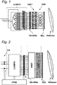
- Fig. 1 illustrates a schematic diagram of a first embodiment of the front-end circuit according to the present invention as applied in a multi-beam array fed reflector antenna system.
- the multi-beam array fed reflector antenna system of Fig. 1 comprises a low-level reconfigurable beam forming network (LLRBFN), a layer of variable bias high power amplifiers (VB-HPAs), a layer of lossless multiport hybrid matrices (output network, ONET), a fixed output scrambling network (OSN), a layer of radiating elements (REs), and a reflector.
- the layer of radiating elements (REs) has a number N E of radiating elements.
- a reconfigurable RF front-end circuit is provided for a multi-beam array fed reflector antenna system having a first plurality of N B input beam signals and a second plurality of N E radiating elements RE.
- the front-end circuit comprises a reconfigurable beam forming network LLRBFN, having a set of N B input ports and distributing each input port signal to a plurality of N A output ports with phase and amplitude control; a plurality of N A high power amplifiers HPA connected to the plurality of N A output ports of the reconfigurable beam forming network LLRBFN; an output network (ONET, OSN) arranged for recombining signals output by the high power amplifiers HPA and feeding the recombined signals to the second plurality of N E radiating elements RE.
- the high power amplifiers HPA are variable bias high power amplifiers VB-HPA.
- the LLRBFN of Fig. 1 has a number N B of input ports and a number N A of output ports configured to receive a number N B of beam signals and to distribute them to a number N A of output ports.
- the number N B of input ports is equal to the number N B of input beams and each input port of the N B input ports is configured to receive one of the N B beam signals.
- the number N A of output ports is equal to the number N A of variable bias high power amplifiers (VB-HPAs).
- the LLRBFN of Fig. 1 is further configured to transmit an input injected into one of the input ports to N A different output ports.
- the low-level reconfigurable beam forming network (LLRBFN) of Fig. 1 comprises a first layer of N B Signal Dividers SD, a second layer of N A ⁇ N B variable attenuators elements WE AMP, a third layer of N A ⁇ N B phase shifters elements WE, a forth layer of N A Signal Combiners SC for combining the signal channels into the plurality of N A output ports.
- the reconfigurable beam forming network comprises a plurality of signal dividers (SD) for distributing each input port signal to a plurality of N A signal channels, each signal channel further comprising an amplitude weighting element (WE AMP) and a phase weighting element (WE PHI), and a plurality of N A signal combiners (SC) for combining the signal channels into the plurality of N A output ports.
- SD signal dividers
- WE AMP amplitude weighting element
- WE PHI phase weighting element
- SC signal combiners
- amplitude and phase weighting elements can be interchanged, or amplitude and phase weighting may be implemented in an integrated weighting element.
- the first layer of N B Signal Dividers SD of Fig. 1 has a number N B of input ports and a number N A ⁇ N B of output ports, and is configured to receive the N B input beam signals and to split each input signal in N A output signals.
- the second layer of N A ⁇ N B variable attenuators elements WE AMP of Fig. 1 has a number N A ⁇ N B of input ports connected to the outputs of the layer SD and a number N A ⁇ N B of output ports.
- the third layer of N A ⁇ N B phase shifters elements WE PHI of Fig. 1 has a number N A ⁇ N B of input ports connected to the outputs of the variable attenuators elements layer and a number N A ⁇ N B of output ports.
- the forth layer of N A Signal Combiners has a number N A ⁇ N B of input ports for combining the signals at the output of the phase shifter layer into the plurality of N A output ports; and is configured in such a way that each signal combiner has N B input signals corresponding to each N B beam signals and combine them in an output signals.
- the layer of variable bias high power amplifiers (VB-HPAs) of Fig. 1 comprises N A variable bias high power amplifiers each one having an input and an output.
- the N A inputs of the active variable bias high power amplifiers are connected to the N A output ports of the LLRBFN.
- the variable bias high power amplifier VB-HPA is a flexible or variable bias solid-state power amplifier (flex-SSPA) in a specific embodiment, or it can be implemented as a flexible or variable bias travelling wave tube amplifier (flex-TWTA).
- the layer of lossless multiport hybrid matrices (ONET) of Fig. 1 comprises a plurality of lossless multiport hybrid matrices, a number N A of input ports and a number N E of output ports.
- Each lossless multiport hybrid matrix may be a Butler network (see description below) or any other suitable device.
- the number N A of input ports is equal to the number of variable bias high power amplifiers VB-HPA and each input port of the N A input ports is connected to a different output port of the N A output ports of the layer of variable bias high power amplifiers VB-HPA.
- the number N E of output ports of the ONET is equal to the number N E of radiating elements RE.
- the fixed output scrambling network (OSN) of Fig. 1 connects each output port of the N E output ports of the ONET to a radiating element RE.
- the OSN interconnection between each lossless multiport hybrid matrix of the ONET and the radiating elements RE is such to obtain an almost uniform distribution of power among the amplifiers independently form the power assigned to the beams.
- Fig. 2 illustrates a schematic diagram of a second embodiment of the front-end circuit applied in a multi-beam array fed reflector antenna system according to a further embodiment of the present invention.
- the multi-beam array fed reflector antenna system of Fig. 2 comprises a first layer of N B channel amplifiers CA (each with a voltage gain a m ), in addition to a low-level reconfigurable beam forming network (LLRBFN) (with voltage gains b nm ), a layer of variable bias high power amplifiers (VB-HPAs, with normalised voltage gain c n ), a layer of lossless multiport hybrid matrices (output network, ONET), a fixed output scrambling network (OSN), a layer of radiating elements (REs), and a reflector (as in the Fig. 1 embodiment). Furthermore a control and power sub-system (CPSS) is provided connected to the reconfigurable beam forming network (LLRBFN) and the variable bias high power amplifiers (VB-HPA).
- CA low-level reconfigurable beam forming network
- VB-HPAs with normalised voltage gain c n
- ONET optical network
- ONET fixed output scrambling network
- Each one of the N B channel amplifiers CA comprises one input configured to receive one of the N B beam signals and one output connected to the LLRBFN.
- the front-end circuit further comprises a set of channel amplifiers (CA) each connected to one of the set of N B input ports of the reconfigurable beam forming network (LLRBFN).
- the LLRBFN of Fig. 2 similar to the embodiment of Fig. 1 , has a number N B of input ports and a number N A of output ports , and is configured to receive the N B outputs of the CA and to transmit an input injected into an input port to N A different output ports.
- the layer of variable bias high power amplifiers (VB-HPAs), the layer of lossless multiport hybrid matrices (ONET), the fixed output scrambling network (OSN) and the layer of radiating elements (REs) of Fig. 2 are similar in structure and function to the VB-HPAs, the ONET, the OSN and the REs of Fig. 1 .
- the CPSS of Fig. 2 is configured to provide amplitude and phase settings for the LLRBFN and for the bias of the VB-HPA, and to supply a DC power associated to the LLRBFN and VB-HPA states, wherein the DC power is less than a power needed to simultaneously operate all the power amplifiers at full power.
- the LLRBFN distributes the input beam signals to all the VB-HPAs with appropriate amplitude and phase.
- the ONET linearly recombines the amplified sub-signals and the OSN associates them to respective radiating elements REs.
- focusing means e.g. a concave reflector, form the transmitted beams whose direction, shape and EIRP depends on the position of the radiating element RE within the array, on the applied amplitude and phase excitations and the bias conditions of the VB-HPAs.
- the cascade of the LLRBFN, VB-HPAs, ONETs and OSN i.e. the reconfigurable RF front-end circuit, controls amplitude and phase excitations of the Radiating Elements REs.
- Fig. 3 illustrates a typical set-up of a plurality of radiating elements as used in an exemplary implementation of a multi-beam array fed reflector antenna system according to the present invention.
- This exemplary radiating elements configuration uses thirty two radiating elements.
- the target coverage shown in Fig. 3 may aim at covering different linguistic zones.
- the baseline number of radiating elements in Fig. 3 may be selected by an appropriate trade-off aimed at fitting the array with the target multi-beam coverage.
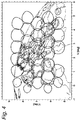
- Fig. 4 illustrates the footprint of the elementary beams generated by the configuration of thirty two radiating elements of Fig. 3 , typical for a geostationary satellite covering the surface of Western Europe.
- the spherical coordinate system used in Fig. 4 refers to the satellite orbital location pointing toward the Earth centre, the horizontal and vertical axes represents the projections of the spherical versor along the north-south and east-west axes in degrees.
- a thirty two radiating elements array may offer a good solution for reconfiguration over a large orbital sector since as it can be seen in Fig.
- the footprint of the elementary beams generated by the radiating elements supply an acceptable coverage all over the required angular sector due to a proper reflector (or platform) repointing depending on the selected satellite position.
- the reconfiguration capability related to the satellite position may be managed by means of antenna re-pointing while the reconfiguration capability related to the beam shaping within the service area may be managed optimizing both the beam forming network weights and the amplifier biasing conditions.
- the baseline RF-Front-End circuit and Antenna architecture used for the configuration of RE's in Fig. 3 and Fig. 4 is similar to the one illustrated in Fig. 1 and Fig. 2 .
- the service is provided by means of shaped beams covering a given region or language homogeneous area.
- Fig. 5 illustrates an exemplary Western Europe coverage with different shaped beams.
- the shaped beams are formed by means of appropriately amplitude and phase combining individual elementary beams.
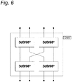
- Fig. 6 illustrates an exemplary 4x4 hybrid matrix constituting the ONET as possibly used in the embodiments of Fig. 1 and Fig. 2 , as well as in the embodiment of Fig. 6 described below.
- the hybrid matrix of Fig. 6 has four inputs, four outputs, and four directional coupler blocks of 3dB/90 degrees. As it can be seen in Fig. 6 , the hybrid matrix linearly combines and phase shifts the inputs.
- the OSN interconnection between each lossless multiport hybrid matrix of the ONET and the radiating elements RE is such to obtain an as uniform as possible distribution of power among the amplifiers independently form the power assigned to the individual beams.
- the table below illustrates an exemplary OSN interconnection of a plurality of lossless multiport hybrid matrices of Fig. 6 to obtain an almost uniform distribution of power among the amplifiers for elementary beam of Fig.4 and the shaped beams exemplified in Fig. 5 as used in the embodiments of Fig. 1 and Fig. 2 .
- Lossless multiport hybrid matrix Radiating Elements A 1, 5, 16, 30 B 2, 17, 28, 32 c 3, 14, 18,27 D 4, 15, 19, 29 E 6, 10, 21,25 F 7, 11, 22, 26 G 8, 12, 23, 31 H 9, 13, 20, 24
- the present invention also extends to a further aspect, i.e. a multi-beam array fed reflector antenna system comprising a first plurality of N B input beam signal inputs, an RF front-end circuit according to any one of the embodiment described herein, and further comprising a reflector receiving radiated signals from the second plurality of N E radiating elements (RE).
- a multi-beam array fed reflector antenna system comprising a first plurality of N B input beam signal inputs, an RF front-end circuit according to any one of the embodiment described herein, and further comprising a reflector receiving radiated signals from the second plurality of N E radiating elements (RE).
- the LLRBFN has maximal reconfigurability.
- the set of output ports N A is equal to the number of high power amplifiers, and the LLRBFN is configured to transmit an input signal injected into an input port to N A different output ports.
- the LLRBFN or the combination of the CA and LLRFBFN, can be built as a Digital Beamforming Network (DBFN).
- DBFN Digital Beamforming Network
- P n A assuming uncorrelated beam signals
- P n SAT is a reference power level for the n-th High Power Amplifier that will be assumed to correspond to the maximum deliverable power (e.g.
- a power amplifier efficiency is defined as the ratio of the output RF-power of a power amplifier to the DC-power it consumes.
- the amplification process introduces nonlinearities that affect the quality of the signal. For this reason, the operating point of the power amplifiers must be selected by trading efficiency versus linearity. Basically, the output power of power amplifiers can be controlled by changing the input power level.
- variable bias high power amplifiers for a desired maximum output power, the efficiency can be controlled by adjusting the bias condition of the power amplifier.
- the power consumption of the power amplifier results are thus determined by the combination of the power amplifier bias conditions and output power.
- SBO Saturation Back-Off
- the bias condition is controlled to vary a saturation back-off (SBO) parameter according to an actual power requirement of each of the variable bias high power amplifiers (VB-HPA) individually, the saturation back-off parameter (SBO) being defined as the ratio of a maximum achievable saturation power to an adjustable saturation power. Consequently, one or more of the power amplifiers can be operated at different Saturation Back-Off (SBO) values related to the output power actually needed for the power amplifier in consideration.
- SBO saturation back-off
- the other parameter is the Output Back-Off (OBO) defined as the ratio of the actual saturation power of the amplifier (i.e. the adjustable saturation power) to the output power in the operational condition under consideration.
- OBO n P n SAT P n A
- the bias condition is controlled to vary an output back-off (OBO) parameter for each of the variable bias high power amplifiers (VB-HPA) individually, the output back-off parameter (OBO) being defined as the ratio of an adjustable saturation power to the actual output power.
- the output back-off (OBO) parameter of the plurality of N A variable bias high power amplifiers (VB-HPA) is equal to or higher than a minimum output back-off parameter value (OBO min ).
- the saturation back-off (SBO) parameter for each of the plurality of N A variable bias high power amplifiers is equal to or lower than a maximum saturation back-off parameter value (SBO max ).
- the saturation back-off parameter for each of the plurality of N A variable bias high power amplifiers is set according to formula (17) wherein n denotes an index for each of the plurality of N A variable bias high power amplifiers (VB-HPA), m denotes an index for each of the plurality of N B input beams, a m is the gain contribution of the respective channel amplifier CA, b n , m is the gain contribution of the respective reconfigurable beam forming network (LLRBFN), and c n is the gain contribution of the variable bias high power amplifier (VB-HPA).
- Each Radiating Elements is fed by an excitation coefficient t k,m .
- EIRP m min ⁇ ⁇ ⁇ ⁇ m EIRP m ⁇ ⁇
- SBO Saturation Back-Off
- a variable bias high power amplifiers (VB-HPA) is calculating by selecting the ceiling value.
- the final objective of the optimization is that the amplitude and phase excitations of all the beams are simultaneously optimized in such a way that the radiative performances are met together with the constraint that the load for each amplifier is kept within a range that allow to operate the amplifier with a good DC-to-RF efficiency and the overall RF-Front-End in an optimum DC-to-EIRP efficiency condition.
- the amplitude and phase optimization procedure consists in a simultaneous optimization of all the LLRBFN coefficients aiming at meeting edge-of-coverage (EOC) EIRP and beam-to-beam isolation for all the active beams taking into account the constraint on the amplifiers' load.
- EOC edge-of-coverage
- the amplitude and phase optimization, with constrained VB-HPA load, can be managed by means of consolidated optimization tools.
- the method further comprises a simultaneous optimization of the coefficients controlling the reconfigurable beam forming networks (LLRBFN).
- the CPSS (as described above with reference to the embodiment of Fig. 2 , but which can also be applied in the embodiment of Fig. 1 ) regulates the amount of power supplied to each amplifier by varying their bias conditions in accordance with the amplifier load.
- the power amplifier is designed to maintain their efficiency over a range output power.
- Configuration D (Semi-Active Multi-Matrix - Phase Only) is similar to the previous configuration C, but with phase only beam forming.
- the configuration D showed almost full freedom in power-to-beam allocation. Thanks to an advanced antenna numerical optimization it has been proven possible to achieve good gain maximization while maintaining control of the beam-to-beam isolation. Nevertheless the attractive feature of full power reconfigurability offered by the Semi-Active Multi-Matrix Phase Only (configuration D) is paid in terms of reduced radiation efficiency with respect to the Semi-Active Multi-Matrix Amplitude & Phase (configuration C), which conversely leads to HPAs oversize and then to reduced efficiency of the amplification section.
- Configuration C and D are prior art configurations, used for comparison purposes.
- Configuration E is an exemplary embodiment according to the present invention.
- the average gain ⁇ G ⁇ is best for configuration C that can exploit all the available degrees of freedom for pattern shaping and it is worst for configuration D that is limited to use only the phase degrees of freedom.
- the amplitude constraints imposed accordingly to the present invention i.e. configuration E) do not affect significantly the radiation performance.
- configuration D achieves the maximum total RF power P Tot RF / P SAT and configuration C the worst, with configuration E achieving an intermediate value.
Landscapes
- Engineering & Computer Science (AREA)
- Physics & Mathematics (AREA)
- Astronomy & Astrophysics (AREA)
- General Physics & Mathematics (AREA)
- Aviation & Aerospace Engineering (AREA)
- Computer Networks & Wireless Communication (AREA)
- Signal Processing (AREA)
- Remote Sensing (AREA)
- Variable-Direction Aerials And Aerial Arrays (AREA)
- Amplifiers (AREA)
Claims (14)
- Circuit frontal RF reconfigurable pour un système d'antenne à réflecteur alimenté par réseau multi-faisceau ayant une première pluralité de N B signaux de faisceau d'entrée et une seconde pluralité de N E éléments rayonnants (RE), le circuit frontal comprenant
un réseau de formation de faisceau reconfigurable (LLRBFN), ayant un ensemble de N B ports d'entrée et distribuant chaque signal de port d'entrée à une pluralité de N A ports de sortie avec une commande de phase et d'amplitude ;
une pluralité de N A amplificateurs haute puissance (VB-HPA) connectés à la pluralité de N A ports de sortie du réseau de formation de faisceau reconfigurable (LLRBFN) ;
un réseau de sortie (ONET, OSN), agencé pour recombiner des signaux délivrés en sortie par les amplificateurs haute puissance (VB-HPA) et fournir les signaux recombinés à la seconde pluralité de N E éléments rayonnants (RE), dans lequel les amplificateurs haute puissance (VB-HPA) sont des amplificateurs haute puissance à polarisation variable (VB-HPA), comprenant en outre
un ensemble d'amplificateurs de canal (CA) chacun connecté à l'un de l'ensemble de N B ports d'entrée du réseau de formation de faisceau reconfigurable (LLRBFN). - Circuit frontal RF reconfigurable selon la revendication 1, dans lequel l'amplificateur haute puissance à polarisation variable (VB-HPA) est un amplificateur de puissance à semi-conducteur flexible.
- Circuit frontal RF reconfigurable selon la revendication 1, dans lequel l'amplificateur haute puissance à polarisation variable (VB-HPA) est un amplificateur à tube à ondes progressives à polarisation variable.
- Circuit frontal RF reconfigurable selon l'une quelconque des revendications 1 à 3, dans lequel le réseau de formation de faisceau reconfigurable (LLRBFN) comprend
une pluralité de diviseurs de signal pour distribuer chaque signal de port d'entrée à une pluralité de N A canaux de signal, chaque canal de signal comprenant en outre un élément de pondération de phase (VVE PHI) et un élément de pondération d'amplitude, et
une pluralité de N A combineurs de signaux pour combiner les canaux de signal dans la pluralité de N A ports de sortie. - Circuit frontal RF reconfigurable selon l'une quelconque des revendications 1 à 4,
comprenant en outre un sous-système de commande et d'alimentation (CPSS) connecté au réseau de formation de faisceau reconfigurable (LLRBFN) et aux amplificateurs haute puissance à polarisation variable (VB-HPA). - Circuit frontal RF reconfigurable selon l'une quelconque des revendications 1 à 5, dans lequel le réseau de sortie (ONET, OSN) comprend des matrices hybrides 4x4.
- Procédé d'exploitation d'un circuit frontal RF pour un système d'antenne à réflecteur alimenté par réseau à faisceaux multiples ayant une première pluralité de Nb signaux de faisceau d'entrée et une seconde pluralité de Ne éléments rayonnants (RE), le procédé comprenant les étapes consistant à :Amplifier, par l'intermédiaire de chacun des Nb amplificateurs de canal (CA), l'un des Nb signaux de faisceau et délivrer en sortie le signal amplifié à un port d'entrée d'un réseau de formation de faisceau reconfigurable (LLRBFN) ;distribuer chaque signal de port d'entrée du réseau de formation de faisceau reconfigurable (LLRBFN) à une pluralité de Na ports de sortie avec une commande de phase et d'amplitude ;amplifier, par l'intermédiaire de chacun d'une pluralité de Na amplificateurs haute puissance à polarisation variable (VB-HPA), un signal reçu depuis l'un respectif des Na ports de sortie du réseau de formation de faisceau reconfigurable (LLRBFN), dans lequel la condition de polarisation de chacun des amplificateurs haute puissance à polarisation variable (VB-HPA) est commandée individuellement ;recombiner, par l'intermédiaire d'un réseau de sortie (ONET, OSN), des signaux délivrés en sortie par les amplificateurs haute puissance (VB-HPA)et alimenter les signaux recombinés à la seconde pluralité de Ne éléments rayonnants (RE).
- Procédé selon la revendication 7, dans lequel la condition de polarisation est commandée pour faire varier un paramètre de réduction de saturation en fonction d'une exigence de puissance réelle de chacun des amplificateurs haute puissance à polarisation variable (VB-HPA) individuellement, le paramètre de réduction de saturation étant défini comme le rapport d'une puissance de saturation atteignable maximale à une puissance de saturation réglable.
- Procédé selon la revendication 8, dans lequel le paramètre de réduction de saturation pour chacun de la pluralité de N A amplificateurs haute puissance à polarisation variable (VB-HPA) est égal ou inférieur à une valeur de paramètre de réduction de saturation maximale.
- Procédé selon la revendication 7, 8 ou 9, dans lequel la condition de polarisation est commandée pour faire varier un paramètre de réduction de puissance de sortie pour chacun des amplificateurs haute puissance de polarisation variable (VB-HPA) individuellement, le paramètre de réduction de puissance de sortie étant défini comme le rapport d'une puissance de saturation ajustable à la puissance de sortie réelle.
- Procédé selon la revendication 10, dans lequel le paramètre de réduction de puissance de sortie de la pluralité de N A amplificateurs haute puissance à polarisation variable (VB-HPA) est égal ou supérieur à une valeur de paramètre de réduction de puissance de sortie minimale.
- Procédé selon la revendication 11, dans lequel le paramètre de réduction de saturation pour chacun de la pluralité de N A amplificateurs haute puissance à polarisation variable (VB-HPA) est réglé selon
 dans lequel n désigne un indice pour chacun de la pluralité de N A amplificateurs haute puissance à polarisation variable (VB-HPA), m désigne un indice pour chacun de la pluralité de N B faisceaux d'entrée,OBOmin est la valeur de paramètre de réduction de sortie minimale,a m est la contribution de gain de l'amplificateur de canal respectif CA,b n,m est la contribution de gain du réseau de formation de faisceau reconfigurable respectif (LLRBFN),et cn est la contribution de gain de l'amplificateur haute puissance à polarisation variable (VB-HPA).
 - Procédé selon l'une quelconque des revendications 8 à 12, comprenant en outre une optimisation simultanée des coefficients commandant les réseaux de formation de faisceau reconfigurables (LLRBFN).
- Système d'antenne à réflecteur alimenté par réseau à faisceaux multiples comprenant une première pluralité d'entrées de signal de faisceau d'entrée NB, un circuit frontal RF selon l'une quelconque des revendications 1 à 6, et comprenant en outre un réflecteur recevant des signaux rayonnés à partir de la seconde pluralité de N A éléments rayonnants (RE).
Applications Claiming Priority (1)
| Application Number | Priority Date | Filing Date | Title |
|---|---|---|---|
| PCT/EP2015/055807 WO2016146195A1 (fr) | 2015-03-19 | 2015-03-19 | Circuit frontal rf reconfigurable destiné à un système d'antenne à réflecteur alimenté à réseau multi-faisceau |
Publications (2)
| Publication Number | Publication Date |
|---|---|
| EP3272028A1 EP3272028A1 (fr) | 2018-01-24 |
| EP3272028B1 true EP3272028B1 (fr) | 2021-09-01 |
Family
ID=52727122
Family Applications (1)
| Application Number | Title | Priority Date | Filing Date |
|---|---|---|---|
| EP15711729.2A Active EP3272028B1 (fr) | 2015-03-19 | 2015-03-19 | Circuit frontal rf reconfigurable destiné à un système d'antenne à réflecteur alimenté à réseau multi-faisceau |
Country Status (3)
| Country | Link |
|---|---|
| US (1) | US10347986B2 (fr) |
| EP (1) | EP3272028B1 (fr) |
| WO (1) | WO2016146195A1 (fr) |
Families Citing this family (4)
| Publication number | Priority date | Publication date | Assignee | Title |
|---|---|---|---|---|
| US10158170B2 (en) * | 2016-01-25 | 2018-12-18 | International Business Machines Corporation | Two-dimensional scanning cylindrical reflector |
| US10177460B2 (en) | 2017-04-24 | 2019-01-08 | Blue Digs LLC | Satellite array architecture |
| CN115801083A (zh) * | 2022-10-24 | 2023-03-14 | 苏州博海创业微系统有限公司 | 一种大规模波束形成矩阵及整机结构 |
| CN120342451B (zh) * | 2025-04-25 | 2026-03-31 | 西安电子科技大学 | 基于孔径分配和饱和功率放大的通感一体化波束成形方法 |
Family Cites Families (7)
| Publication number | Priority date | Publication date | Assignee | Title |
|---|---|---|---|---|
| FR2652452B1 (fr) * | 1989-09-26 | 1992-03-20 | Europ Agence Spatiale | Dispositif d'alimentation d'une antenne a faisceaux multiples. |
| US5119042A (en) * | 1990-08-30 | 1992-06-02 | Hughes Aircraft Company | Solid state power amplifier with dynamically adjusted operating point |
| US6871049B2 (en) * | 2002-03-21 | 2005-03-22 | Cognio, Inc. | Improving the efficiency of power amplifiers in devices using transmit beamforming |
| US7221907B2 (en) | 2003-02-12 | 2007-05-22 | The Boeing Company | On orbit variable power high power amplifiers for a satellite communications system |
| US7181163B2 (en) * | 2003-05-05 | 2007-02-20 | Agence Spatiale Europeenne | Multi-beam satellite communications payload with flexible power allocation |
| FR2860648B1 (fr) | 2003-10-03 | 2006-02-24 | Agence Spatiale Europeenne | Antenne de satellite de communication multi-faisceaux presentant une compensation de defaillance |
| EP2296225B1 (fr) * | 2009-09-10 | 2018-05-09 | Agence Spatiale Européenne | Architecture reconfigurable de réseau de formation de faisceaux |
-
2015
- 2015-03-19 US US15/559,064 patent/US10347986B2/en active Active
- 2015-03-19 EP EP15711729.2A patent/EP3272028B1/fr active Active
- 2015-03-19 WO PCT/EP2015/055807 patent/WO2016146195A1/fr not_active Ceased
Also Published As
| Publication number | Publication date |
|---|---|
| US10347986B2 (en) | 2019-07-09 |
| EP3272028A1 (fr) | 2018-01-24 |
| WO2016146195A1 (fr) | 2016-09-22 |
| US20180076519A1 (en) | 2018-03-15 |
Similar Documents
| Publication | Publication Date | Title |
|---|---|---|
| US11863255B2 (en) | Power control to a beam steering phased array antenna in satellite applications | |
| US5936592A (en) | Reconfigurable multiple beam satellite reflector antenna with an array feed | |
| US5115248A (en) | Multibeam antenna feed device | |
| US6246364B1 (en) | Light-weight modular low-level reconfigurable beamformer for array antennas | |
| Abdel-Wahab et al. | A modular architecture for wide scan angle phased array antenna for K/Ka mobile SATCOM | |
| US4825172A (en) | Equal power amplifier system for active phase array antenna and method of arranging same | |
| US8354956B2 (en) | Space segment payload architecture for mobile satellite services (MSS) systems | |
| US11699850B2 (en) | Method and apparatus for beam steering and switching | |
| EP3272028B1 (fr) | Circuit frontal rf reconfigurable destiné à un système d'antenne à réflecteur alimenté à réseau multi-faisceau | |
| US12489206B2 (en) | Multi-beam antenna using higher-order modes | |
| US5204686A (en) | RF Feed array | |
| Ruggerini et al. | A Ka-band active aperiodic constrained lens antenna for multibeam applications: Active discrete lens antennas are promising alternative solutions for multibeam coverage using a single aperture | |
| EP1972030B1 (fr) | Charge reconfigurable utilisant une antenne de reflecteur non ciblee pour des satellites hieo et geo | |
| US20040224633A1 (en) | Multi-beam satellite communications payload with flexible power allocation | |
| GB2315644A (en) | Geosynchronous communications satellite system with reconfigurable service area | |
| CN113745854A (zh) | 一种相控阵发射多波束天线系统 | |
| JP3411223B2 (ja) | アンテナ装置 | |
| JPH08102618A (ja) | マルチビームアンテナ | |
| Lier et al. | Techniques to maximize communication traffic capacity in multi-beam satellite active phased array antennas for non-uniform traffic model | |
| JPH10229308A (ja) | ビーム走査アンテナ装置 | |
| Oldoni et al. | Phased Array Design for Bounded-Power Consumption Onboard Spacecraft | |
| JPH1093337A (ja) | マルチビームアンテナ | |
| Angeletti et al. | Study of a flexible payload for S-band mobile broadcasting to multiple shaped beams | |
| Zaghloul et al. | Design and performance assessment of active phased arrays for communications satellites | |
| Rao et al. | Phased Array Antenna Design for Transmit Applications |
Legal Events
| Date | Code | Title | Description |
|---|---|---|---|
| STAA | Information on the status of an ep patent application or granted ep patent |
Free format text: STATUS: THE INTERNATIONAL PUBLICATION HAS BEEN MADE |
|
| PUAI | Public reference made under article 153(3) epc to a published international application that has entered the european phase |
Free format text: ORIGINAL CODE: 0009012 |
|
| STAA | Information on the status of an ep patent application or granted ep patent |
Free format text: STATUS: REQUEST FOR EXAMINATION WAS MADE |
|
| 17P | Request for examination filed |
Effective date: 20170919 |
|
| AK | Designated contracting states |
Kind code of ref document: A1 Designated state(s): AL AT BE BG CH CY CZ DE DK EE ES FI FR GB GR HR HU IE IS IT LI LT LU LV MC MK MT NL NO PL PT RO RS SE SI SK SM TR |
|
| AX | Request for extension of the european patent |
Extension state: BA ME |
|
| DAV | Request for validation of the european patent (deleted) | ||
| DAX | Request for extension of the european patent (deleted) | ||
| STAA | Information on the status of an ep patent application or granted ep patent |
Free format text: STATUS: EXAMINATION IS IN PROGRESS |
|
| 17Q | First examination report despatched |
Effective date: 20181206 |
|
| GRAP | Despatch of communication of intention to grant a patent |
Free format text: ORIGINAL CODE: EPIDOSNIGR1 |
|
| STAA | Information on the status of an ep patent application or granted ep patent |
Free format text: STATUS: GRANT OF PATENT IS INTENDED |
|
| INTG | Intention to grant announced |
Effective date: 20210503 |
|
| GRAS | Grant fee paid |
Free format text: ORIGINAL CODE: EPIDOSNIGR3 |
|
| GRAA | (expected) grant |
Free format text: ORIGINAL CODE: 0009210 |
|
| STAA | Information on the status of an ep patent application or granted ep patent |
Free format text: STATUS: THE PATENT HAS BEEN GRANTED |
|
| AK | Designated contracting states |
Kind code of ref document: B1 Designated state(s): AL AT BE BG CH CY CZ DE DK EE ES FI FR GB GR HR HU IE IS IT LI LT LU LV MC MK MT NL NO PL PT RO RS SE SI SK SM TR |
|
| REG | Reference to a national code |
Ref country code: GB Ref legal event code: FG4D |
|
| REG | Reference to a national code |
Ref country code: CH Ref legal event code: EP Ref country code: AT Ref legal event code: REF Ref document number: 1427321 Country of ref document: AT Kind code of ref document: T Effective date: 20210915 |
|
| REG | Reference to a national code |
Ref country code: DE Ref legal event code: R096 Ref document number: 602015072832 Country of ref document: DE |
|
| REG | Reference to a national code |
Ref country code: IE Ref legal event code: FG4D |
|
| REG | Reference to a national code |
Ref country code: LT Ref legal event code: MG9D |
|
| REG | Reference to a national code |
Ref country code: NL Ref legal event code: MP Effective date: 20210901 |
|
| PG25 | Lapsed in a contracting state [announced via postgrant information from national office to epo] |
Ref country code: HR Free format text: LAPSE BECAUSE OF FAILURE TO SUBMIT A TRANSLATION OF THE DESCRIPTION OR TO PAY THE FEE WITHIN THE PRESCRIBED TIME-LIMIT Effective date: 20210901 Ref country code: SE Free format text: LAPSE BECAUSE OF FAILURE TO SUBMIT A TRANSLATION OF THE DESCRIPTION OR TO PAY THE FEE WITHIN THE PRESCRIBED TIME-LIMIT Effective date: 20210901 Ref country code: RS Free format text: LAPSE BECAUSE OF FAILURE TO SUBMIT A TRANSLATION OF THE DESCRIPTION OR TO PAY THE FEE WITHIN THE PRESCRIBED TIME-LIMIT Effective date: 20210901 Ref country code: LT Free format text: LAPSE BECAUSE OF FAILURE TO SUBMIT A TRANSLATION OF THE DESCRIPTION OR TO PAY THE FEE WITHIN THE PRESCRIBED TIME-LIMIT Effective date: 20210901 Ref country code: BG Free format text: LAPSE BECAUSE OF FAILURE TO SUBMIT A TRANSLATION OF THE DESCRIPTION OR TO PAY THE FEE WITHIN THE PRESCRIBED TIME-LIMIT Effective date: 20211201 Ref country code: NO Free format text: LAPSE BECAUSE OF FAILURE TO SUBMIT A TRANSLATION OF THE DESCRIPTION OR TO PAY THE FEE WITHIN THE PRESCRIBED TIME-LIMIT Effective date: 20211201 Ref country code: ES Free format text: LAPSE BECAUSE OF FAILURE TO SUBMIT A TRANSLATION OF THE DESCRIPTION OR TO PAY THE FEE WITHIN THE PRESCRIBED TIME-LIMIT Effective date: 20210901 Ref country code: FI Free format text: LAPSE BECAUSE OF FAILURE TO SUBMIT A TRANSLATION OF THE DESCRIPTION OR TO PAY THE FEE WITHIN THE PRESCRIBED TIME-LIMIT Effective date: 20210901 |
|
| REG | Reference to a national code |
Ref country code: AT Ref legal event code: MK05 Ref document number: 1427321 Country of ref document: AT Kind code of ref document: T Effective date: 20210901 |
|
| PG25 | Lapsed in a contracting state [announced via postgrant information from national office to epo] |
Ref country code: PL Free format text: LAPSE BECAUSE OF FAILURE TO SUBMIT A TRANSLATION OF THE DESCRIPTION OR TO PAY THE FEE WITHIN THE PRESCRIBED TIME-LIMIT Effective date: 20210901 Ref country code: LV Free format text: LAPSE BECAUSE OF FAILURE TO SUBMIT A TRANSLATION OF THE DESCRIPTION OR TO PAY THE FEE WITHIN THE PRESCRIBED TIME-LIMIT Effective date: 20210901 Ref country code: GR Free format text: LAPSE BECAUSE OF FAILURE TO SUBMIT A TRANSLATION OF THE DESCRIPTION OR TO PAY THE FEE WITHIN THE PRESCRIBED TIME-LIMIT Effective date: 20211202 |
|
| PG25 | Lapsed in a contracting state [announced via postgrant information from national office to epo] |
Ref country code: AT Free format text: LAPSE BECAUSE OF FAILURE TO SUBMIT A TRANSLATION OF THE DESCRIPTION OR TO PAY THE FEE WITHIN THE PRESCRIBED TIME-LIMIT Effective date: 20210901 |
|
| PG25 | Lapsed in a contracting state [announced via postgrant information from national office to epo] |
Ref country code: IS Free format text: LAPSE BECAUSE OF FAILURE TO SUBMIT A TRANSLATION OF THE DESCRIPTION OR TO PAY THE FEE WITHIN THE PRESCRIBED TIME-LIMIT Effective date: 20220101 Ref country code: SM Free format text: LAPSE BECAUSE OF FAILURE TO SUBMIT A TRANSLATION OF THE DESCRIPTION OR TO PAY THE FEE WITHIN THE PRESCRIBED TIME-LIMIT Effective date: 20210901 Ref country code: SK Free format text: LAPSE BECAUSE OF FAILURE TO SUBMIT A TRANSLATION OF THE DESCRIPTION OR TO PAY THE FEE WITHIN THE PRESCRIBED TIME-LIMIT Effective date: 20210901 Ref country code: RO Free format text: LAPSE BECAUSE OF FAILURE TO SUBMIT A TRANSLATION OF THE DESCRIPTION OR TO PAY THE FEE WITHIN THE PRESCRIBED TIME-LIMIT Effective date: 20210901 Ref country code: PT Free format text: LAPSE BECAUSE OF FAILURE TO SUBMIT A TRANSLATION OF THE DESCRIPTION OR TO PAY THE FEE WITHIN THE PRESCRIBED TIME-LIMIT Effective date: 20220103 Ref country code: NL Free format text: LAPSE BECAUSE OF FAILURE TO SUBMIT A TRANSLATION OF THE DESCRIPTION OR TO PAY THE FEE WITHIN THE PRESCRIBED TIME-LIMIT Effective date: 20210901 Ref country code: EE Free format text: LAPSE BECAUSE OF FAILURE TO SUBMIT A TRANSLATION OF THE DESCRIPTION OR TO PAY THE FEE WITHIN THE PRESCRIBED TIME-LIMIT Effective date: 20210901 Ref country code: CZ Free format text: LAPSE BECAUSE OF FAILURE TO SUBMIT A TRANSLATION OF THE DESCRIPTION OR TO PAY THE FEE WITHIN THE PRESCRIBED TIME-LIMIT Effective date: 20210901 Ref country code: AL Free format text: LAPSE BECAUSE OF FAILURE TO SUBMIT A TRANSLATION OF THE DESCRIPTION OR TO PAY THE FEE WITHIN THE PRESCRIBED TIME-LIMIT Effective date: 20210901 |
|
| REG | Reference to a national code |
Ref country code: DE Ref legal event code: R097 Ref document number: 602015072832 Country of ref document: DE |
|
| PLBE | No opposition filed within time limit |
Free format text: ORIGINAL CODE: 0009261 |
|
| STAA | Information on the status of an ep patent application or granted ep patent |
Free format text: STATUS: NO OPPOSITION FILED WITHIN TIME LIMIT |
|
| PG25 | Lapsed in a contracting state [announced via postgrant information from national office to epo] |
Ref country code: IT Free format text: LAPSE BECAUSE OF FAILURE TO SUBMIT A TRANSLATION OF THE DESCRIPTION OR TO PAY THE FEE WITHIN THE PRESCRIBED TIME-LIMIT Effective date: 20210901 Ref country code: DK Free format text: LAPSE BECAUSE OF FAILURE TO SUBMIT A TRANSLATION OF THE DESCRIPTION OR TO PAY THE FEE WITHIN THE PRESCRIBED TIME-LIMIT Effective date: 20210901 |
|
| 26N | No opposition filed |
Effective date: 20220602 |
|
| PG25 | Lapsed in a contracting state [announced via postgrant information from national office to epo] |
Ref country code: SI Free format text: LAPSE BECAUSE OF FAILURE TO SUBMIT A TRANSLATION OF THE DESCRIPTION OR TO PAY THE FEE WITHIN THE PRESCRIBED TIME-LIMIT Effective date: 20210901 |
|
| PG25 | Lapsed in a contracting state [announced via postgrant information from national office to epo] |
Ref country code: MC Free format text: LAPSE BECAUSE OF FAILURE TO SUBMIT A TRANSLATION OF THE DESCRIPTION OR TO PAY THE FEE WITHIN THE PRESCRIBED TIME-LIMIT Effective date: 20210901 |
|
| REG | Reference to a national code |
Ref country code: BE Ref legal event code: MM Effective date: 20220331 |
|
| PG25 | Lapsed in a contracting state [announced via postgrant information from national office to epo] |
Ref country code: LU Free format text: LAPSE BECAUSE OF NON-PAYMENT OF DUE FEES Effective date: 20220319 Ref country code: IE Free format text: LAPSE BECAUSE OF NON-PAYMENT OF DUE FEES Effective date: 20220319 |
|
| PG25 | Lapsed in a contracting state [announced via postgrant information from national office to epo] |
Ref country code: BE Free format text: LAPSE BECAUSE OF NON-PAYMENT OF DUE FEES Effective date: 20220331 |
|
| PG25 | Lapsed in a contracting state [announced via postgrant information from national office to epo] |
Ref country code: HU Free format text: LAPSE BECAUSE OF FAILURE TO SUBMIT A TRANSLATION OF THE DESCRIPTION OR TO PAY THE FEE WITHIN THE PRESCRIBED TIME-LIMIT; INVALID AB INITIO Effective date: 20150319 |
|
| PG25 | Lapsed in a contracting state [announced via postgrant information from national office to epo] |
Ref country code: MK Free format text: LAPSE BECAUSE OF FAILURE TO SUBMIT A TRANSLATION OF THE DESCRIPTION OR TO PAY THE FEE WITHIN THE PRESCRIBED TIME-LIMIT Effective date: 20210901 Ref country code: CY Free format text: LAPSE BECAUSE OF FAILURE TO SUBMIT A TRANSLATION OF THE DESCRIPTION OR TO PAY THE FEE WITHIN THE PRESCRIBED TIME-LIMIT Effective date: 20210901 |
|
| PG25 | Lapsed in a contracting state [announced via postgrant information from national office to epo] |
Ref country code: MT Free format text: LAPSE BECAUSE OF FAILURE TO SUBMIT A TRANSLATION OF THE DESCRIPTION OR TO PAY THE FEE WITHIN THE PRESCRIBED TIME-LIMIT Effective date: 20210901 |
|
| PGFP | Annual fee paid to national office [announced via postgrant information from national office to epo] |
Ref country code: CH Payment date: 20250401 Year of fee payment: 11 |
|
| PG25 | Lapsed in a contracting state [announced via postgrant information from national office to epo] |
Ref country code: TR Free format text: LAPSE BECAUSE OF FAILURE TO SUBMIT A TRANSLATION OF THE DESCRIPTION OR TO PAY THE FEE WITHIN THE PRESCRIBED TIME-LIMIT Effective date: 20210901 |
|
| REG | Reference to a national code |
Ref country code: CH Ref legal event code: U11 Free format text: ST27 STATUS EVENT CODE: U-0-0-U10-U11 (AS PROVIDED BY THE NATIONAL OFFICE) Effective date: 20260401 |
|
| PGFP | Annual fee paid to national office [announced via postgrant information from national office to epo] |
Ref country code: GB Payment date: 20260324 Year of fee payment: 12 |
|
| PGFP | Annual fee paid to national office [announced via postgrant information from national office to epo] |
Ref country code: DE Payment date: 20260319 Year of fee payment: 12 |
|
| PGFP | Annual fee paid to national office [announced via postgrant information from national office to epo] |
Ref country code: FR Payment date: 20260320 Year of fee payment: 12 |