EP3272552B1 - Pneumatique - Google Patents
Pneumatique Download PDFInfo
- Publication number
- EP3272552B1 EP3272552B1 EP16765007.6A EP16765007A EP3272552B1 EP 3272552 B1 EP3272552 B1 EP 3272552B1 EP 16765007 A EP16765007 A EP 16765007A EP 3272552 B1 EP3272552 B1 EP 3272552B1
- Authority
- EP
- European Patent Office
- Prior art keywords
- groove
- air
- air intake
- guiding
- tire
- Prior art date
- Legal status (The legal status is an assumption and is not a legal conclusion. Google has not performed a legal analysis and makes no representation as to the accuracy of the status listed.)
- Active
Links
Images







Classifications
-
- B—PERFORMING OPERATIONS; TRANSPORTING
- B60—VEHICLES IN GENERAL
- B60C—VEHICLE TYRES; TYRE INFLATION; TYRE CHANGING; CONNECTING VALVES TO INFLATABLE ELASTIC BODIES IN GENERAL; DEVICES OR ARRANGEMENTS RELATED TO TYRES
- B60C11/00—Tyre tread bands; Tread patterns; Anti-skid inserts
- B60C11/03—Tread patterns
- B60C11/0311—Patterns comprising tread lugs arranged parallel or oblique to the axis of rotation
-
- B—PERFORMING OPERATIONS; TRANSPORTING
- B60—VEHICLES IN GENERAL
- B60C—VEHICLE TYRES; TYRE INFLATION; TYRE CHANGING; CONNECTING VALVES TO INFLATABLE ELASTIC BODIES IN GENERAL; DEVICES OR ARRANGEMENTS RELATED TO TYRES
- B60C11/00—Tyre tread bands; Tread patterns; Anti-skid inserts
- B60C11/03—Tread patterns
- B60C11/13—Tread patterns characterised by the groove cross-section, e.g. for buttressing or preventing stone-trapping
- B60C11/1307—Tread patterns characterised by the groove cross-section, e.g. for buttressing or preventing stone-trapping with special features of the groove walls
-
- B—PERFORMING OPERATIONS; TRANSPORTING
- B60—VEHICLES IN GENERAL
- B60C—VEHICLE TYRES; TYRE INFLATION; TYRE CHANGING; CONNECTING VALVES TO INFLATABLE ELASTIC BODIES IN GENERAL; DEVICES OR ARRANGEMENTS RELATED TO TYRES
- B60C11/00—Tyre tread bands; Tread patterns; Anti-skid inserts
- B60C11/03—Tread patterns
- B60C11/032—Patterns comprising isolated recesses
-
- B—PERFORMING OPERATIONS; TRANSPORTING
- B60—VEHICLES IN GENERAL
- B60C—VEHICLE TYRES; TYRE INFLATION; TYRE CHANGING; CONNECTING VALVES TO INFLATABLE ELASTIC BODIES IN GENERAL; DEVICES OR ARRANGEMENTS RELATED TO TYRES
- B60C11/00—Tyre tread bands; Tread patterns; Anti-skid inserts
- B60C11/03—Tread patterns
- B60C2011/0337—Tread patterns characterised by particular design features of the pattern
- B60C2011/0339—Grooves
- B60C2011/0358—Lateral grooves, i.e. having an angle of 45 to 90 degees to the equatorial plane
- B60C2011/0365—Lateral grooves, i.e. having an angle of 45 to 90 degees to the equatorial plane characterised by width
-
- B—PERFORMING OPERATIONS; TRANSPORTING
- B60—VEHICLES IN GENERAL
- B60C—VEHICLE TYRES; TYRE INFLATION; TYRE CHANGING; CONNECTING VALVES TO INFLATABLE ELASTIC BODIES IN GENERAL; DEVICES OR ARRANGEMENTS RELATED TO TYRES
- B60C11/00—Tyre tread bands; Tread patterns; Anti-skid inserts
- B60C11/03—Tread patterns
- B60C2011/0337—Tread patterns characterised by particular design features of the pattern
- B60C2011/0339—Grooves
- B60C2011/0358—Lateral grooves, i.e. having an angle of 45 to 90 degees to the equatorial plane
- B60C2011/0367—Lateral grooves, i.e. having an angle of 45 to 90 degees to the equatorial plane characterised by depth
-
- B—PERFORMING OPERATIONS; TRANSPORTING
- B60—VEHICLES IN GENERAL
- B60C—VEHICLE TYRES; TYRE INFLATION; TYRE CHANGING; CONNECTING VALVES TO INFLATABLE ELASTIC BODIES IN GENERAL; DEVICES OR ARRANGEMENTS RELATED TO TYRES
- B60C11/00—Tyre tread bands; Tread patterns; Anti-skid inserts
- B60C11/03—Tread patterns
- B60C2011/0337—Tread patterns characterised by particular design features of the pattern
- B60C2011/0339—Grooves
- B60C2011/0358—Lateral grooves, i.e. having an angle of 45 to 90 degees to the equatorial plane
- B60C2011/0367—Lateral grooves, i.e. having an angle of 45 to 90 degees to the equatorial plane characterised by depth
- B60C2011/0369—Lateral grooves, i.e. having an angle of 45 to 90 degees to the equatorial plane characterised by depth with varying depth of the groove
-
- B—PERFORMING OPERATIONS; TRANSPORTING
- B60—VEHICLES IN GENERAL
- B60C—VEHICLE TYRES; TYRE INFLATION; TYRE CHANGING; CONNECTING VALVES TO INFLATABLE ELASTIC BODIES IN GENERAL; DEVICES OR ARRANGEMENTS RELATED TO TYRES
- B60C11/00—Tyre tread bands; Tread patterns; Anti-skid inserts
- B60C11/03—Tread patterns
- B60C2011/0337—Tread patterns characterised by particular design features of the pattern
- B60C2011/0339—Grooves
- B60C2011/0381—Blind or isolated grooves
- B60C2011/0383—Blind or isolated grooves at the centre of the tread
-
- B—PERFORMING OPERATIONS; TRANSPORTING
- B60—VEHICLES IN GENERAL
- B60C—VEHICLE TYRES; TYRE INFLATION; TYRE CHANGING; CONNECTING VALVES TO INFLATABLE ELASTIC BODIES IN GENERAL; DEVICES OR ARRANGEMENTS RELATED TO TYRES
- B60C2200/00—Tyres specially adapted for particular applications
- B60C2200/06—Tyres specially adapted for particular applications for heavy duty vehicles
- B60C2200/065—Tyres specially adapted for particular applications for heavy duty vehicles for construction vehicles
Definitions
- the present invention relates to a tire, and in particular, relates to a tire suitable for mounting on large vehicles, particularly construction vehicles.
- a pneumatic tire used for large vehicles such as a vehicle construction machine has a thickness of a tread section larger than that of other vehicles.
- the temperature of the tread section, particularly in a deep portion thereof, of a tire heated accompanying work or running of a large vehicle is hard to bring down by natural heat dissipation in the atmosphere.
- Patent Literature 1 previously providing a plurality of air intake grooves of air and air introduction grooves of air communicating with each air intake groove in a tire circumferential direction in a tread section of the tire has been proposed (see Patent Literature 1).
- the air received after being introduced into the air intake groove through the air introduction groove flows in a longitudinal direction inside the air intake groove, and in the meantime, the neighborhood of a groove bottom of the air intake groove, and therefore, the neighborhood of a deep portion of the tread section is cooled.
- the air introduced into the air intake groove may flow through a relatively shallow portion below an open surface of the air intake groove, instead of the neighborhood of the groove bottom of the air intake groove, and therefore, the deep portion of the tread section, where the temperature is relatively high, may not be sufficiently cooled.
- Patent Literature 1 WO 2013-035889 .
- WO2008/029563-A1 and EP0847878-A2 show tires being relevant for the invention with an air intake groove, an air introduction groove and an air-guiding section.
- the present invention is made in view of the above problem and a subject thereof is to provide a tire capable of sufficiently cooling a deep portion of a tread section by efficiently fluidizing the air in the deep portion of the tread section or the neighborhood thereof.
- a tire according to first aspect of the present invention includes at least one air intake groove provided in a tire tread section, extending in a direction intersecting a tire circumferential direction, and having a groove width smaller than a groove depth; an air introduction groove opening to a tread surface side and communicating with the air intake groove to introduce an air on the tread surface side into the air intake groove accompanying tire rotation; and an air-guiding section having an air-guiding surface which intersects the air intake groove and which is directed outward in a position intersecting the air intake groove with respect to a center position in a groove longitudinal direction of the air intake groove, the air-guiding surface guiding an air introduced into the air intake groove by the air introduction groove to a groove bottom side of the air intake groove, wherein the air introduction groove is made of an inclined surface inclined from the tread surface toward the inner side in a tire radial direction, the inclination angle of the inclined surface of the air introduction grooves, with respect to the tread surface is 45° or less.
- the air introduction groove communicates with a groove wall surface on one side of groove wall surfaces opposite to each other in the tire circumferential direction of the air intake groove.
- the air-guiding section communicates with the air intake groove, communicates with the groove wall surface on the other side of the groove wall surfaces opposite to each other in the tire radial direction of the air intake groove, has an outer side end in the tire circumferential direction on an outer side in a tire radial direction from a radial direction position where the air introduction groove and the air intake groove intersect, and has an inner side end in the tire radial direction on an inner side in the tire radial direction from a position half a groove depth of the air intake groove, wherein the air-guiding section comprises includes an air-guiding groove partially opposed to the air introduction groove at least in the tire circumferential direction.
- the air-guiding section protrudes in a groove width direction of the air intake groove by being arranged on the groove wall of the air intake groove and includes an air-guiding protrusion extending in the tire radial direction toward the groove bottom.
- the air-guiding protrusion guides an air guided into the air intake groove by the air introduction groove accompanying the tire rotation to the groove bottom side of the air intake groove.
- the present invention provides a tire capable of sufficiently cooling a deep portion of a tread section by efficiently fluidizing the air in the deep portion of the tread section or the neighborhood thereof.
- a portion of the surface of a tread section 12 of a tire 10 is schematically shown in a state expanded on a flat surface.
- the tire 10 is made of a pneumatic tire used for large vehicles like vehicle construction machines.
- the tread section 12 of the tire 10 includes any pattern (tread pattern).
- the tread pattern shown in Fig. 1 includes a pair of circumferential grooves 16 extending in a tire circumferential direction (an up and down direction in Fig. 1 ) and a plurality of width direction grooves 18 extending in a tire width direction (a left and right direction in Fig. 1 ). Both of the circumferential grooves 16 are positioned on both sides of an equatorial plane CL of the tire 10.
- the plurality of width direction grooves 18 is arranged equidistantly to each other in the tire circumferential direction between each of the circumferential grooves 16 and each tread end TE. One end of each of the width direction grooves 18 communicates with each of the circumferential grooves 16 and the other end thereof ends at each tread end TE.
- the tread pattern includes a center land section 20 partitioned by both of the circumferential grooves 16 therebetween and extending in the tire circumferential direction and a block-like land section 21 partitioned by the two width direction grooves 18 adjacent to each other therebetween in the tire circumferential direction.
- the surface of the center land section 20 and that of the block-like land section 21 each define practically the tread of the tire 10.
- the tread pattern of the tread section 12 may be made of what is called a lib pattern, a lug pattern, or a block pattern.
- the width direction grooves 18 may, for example, extend in a direction intersecting the width direction or have mutually different width dimensions.
- the tire 10 includes at least one, in the illustrated example, a plurality of air intake grooves 22 provided in the tread section 12 to release heat generated in the tread section 12 accompanying work or running of the vehicle mounted therewith and opening to the surface of the center land section 20 defining the tread, a set of an air introduction groove 24 and an air-guiding groove (air-guiding section) 26 communicating with each of the air intake grooves 22, and another set of another air introduction groove 28 and another air-guiding groove (air-guiding section) 30.
- these grooves 22 to 30 may be provided in each of the block-like land sections 21.
- the air introduction grooves 24, 28 are each provided so as to be positioned forward and backward in one direction when the tire 10 rotates in the one direction for work or running of the vehicle.
- the air introduction groove 24 serves to introduce the air (atmosphere) flowing into the air introduction groove 24 when the tire 10 rotates in the one direction into the air intake groove 22,
- the air intake groove 22 serves to receive the air introduced thereinto, and
- the air-guiding groove 26 serves to guide the air introduced into the air intake groove 22 toward the groove bottom of the air intake groove 22.
- the other air introduction groove 28 serves as an outflow path of the air after the inside of the air intake groove 22 being fluidized.
- the other air introduction groove 28 serves to introduce the air flowing into the other air introduction groove 28 when the tire 10 rotates in the opposite direction into the air intake groove 22 and the air-guiding groove 30 serves to guide the air introduced into the air intake groove 22 toward the groove bottom of the air intake groove 22.
- the air introduction groove 24 serves as an outflow path of the air after the inside of the air intake groove 22 being fluidized.
- the air fluidized inside the air intake groove 22 serves to deprive the tread section 12 of heat during fluidization.
- the plurality of air intake grooves 22 each opens to the surface of the center land section 20 (tread of the tire 10) constituting the tread section 12.
- the plurality of air intake grooves 22 is arranged equidistantly to each other in the tire circumferential direction in parallel with each other.
- the plurality of air intake grooves 22 may be arranged at mutually different intervals or to be non-parallel to each other.
- the air intake groove 22 extends in a direction intersecting the tire circumferential direction. That is, the air intake groove 22 extends non-parallel thereto.
- An intersection angle ⁇ is set so as to be in a range of 0° ⁇ ⁇ ⁇ 90°, preferably 0° ⁇ ⁇ ⁇ 60°.
- the air intake groove 22 illustrated has one end and the other end in a longitudinal direction thereof within the center land section 20.
- the air intake groove 22 extends within the center land section 20 and also terminates within the center land section 20.
- Both or one of both ends in the longitudinal direction of the air intake groove 22 may communicate with both or one of both of the circumferential grooves 16, but in consideration of degradation of rigidity of the center land section 20, it is desirable, as in the illustrated example, to be non-communicating.
- each of the air intake grooves 22 has a U-shaped cross-sectional shape and includes groove wall surfaces 22a, 22b defining the cross-sectional shape and made of a pair of flat surfaces opposite to each other and a groove bottom 22c linked to both of the groove wall surfaces 22a, 22b and made of a flat surface.
- the air intake groove 22 may have, for example, a V-shaped cross-sectional shape.
- each of a pair of groove wall surfaces opposite to each other is made of a flat surface and the groove bottom is made of an intersection portion of both groove wall surfaces and forms a linear line.
- a groove width W and a groove depth D (see Fig. 2 ) of each of the air intake grooves 22 are set such that the relation W ⁇ D is satisfied to limit the degradation of rigidity of the tread section 12, more specifically the degradation of rigidity of the center land section 20 caused by the air intake groove 22 being provided.
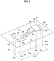
- a set of the air introduction groove 24 and the air-guiding groove 26 of two sets of the air introduction grooves and air-guiding grooves, and another set of the other air introduction groove 28 and the other air-guiding groove 30 are arranged by leaving a space to each other in the longitudinal direction of the air intake groove and arranged, in the example illustrated in Fig. 2 , at both ends in the longitudinal direction of the air intake groove 22.
- only one of the two sets (for example, the one set of the air introduction groove 24 and the air-guiding groove 26) may be provided at one of both ends of the air intake groove 22.
- only one of the two sets (for example, the one set of the air introduction groove 24 and the air-guiding groove 26) may be provided at one end of the air intake groove 22 and only the air introduction groove 28 may be provided at the other end of the air intake groove 22.
- the air introduction grooves 24, 28 each open to the surface (tread) of the center land section 20. Accordingly, the air can be taken into the air introduction grooves 24, 28 from around the tire 10.
- the air introduction grooves 24, 28 each extend in any direction, preferably in the tire circumferential direction. Accordingly, the flow of air into the air introduction grooves 24, 28 can be smoothed.
- the air introduction grooves 24, 28 each communicate with the air intake groove 22 to open to the air intake groove on the one 22a and the other 22b of both of the groove wall surfaces 22a, 22b defining the groove width W ( Fig. 2 ) of the air intake groove 22. This enables the intake of the air when the tire 10 rotates in the one direction or the opposite direction and the introduction of the air into the air intake groove 22.
- One air introduction groove 24 has a U-shaped cross-sectional shape and includes groove wall surfaces 24a, 24b defining the cross-sectional shape and made of a pair of flat surfaces opposite to each other and a groove bottom 24c linked to both of these groove wall surfaces and made of a flat surface and the groove bottom 24c intersects one groove wall surface 22a of the air intake groove 22.
- the other air introduction groove 28 also has, as with the air introduction groove 24, a U-shaped cross-sectional shape and includes groove wall surfaces 28a, 28b defining the cross-sectional shape and made of a pair of flat surfaces opposite to each other and a groove bottom 28c linked to both of these groove wall surfaces 28a, 28b and made of a flat surface and the groove bottom 28c intersects the other groove wall surface 22b of the air intake groove 22.
- each of the air introduction grooves 24, 28 may have, for example, a V-shaped cross-sectional shape.
- each of a pair of groove wall surfaces opposite to each other is made of a flat surface and the groove bottom is made of an intersection portion of both groove wall surfaces and forms a linear line.
- the groove bottom 24c of the air introduction groove 24 and the groove bottom 28c of the air introduction groove 28 are each made of an inclined surface inclined from the surface (tread) of the center land section 20 toward the inner side in a tire radial direction.
- the depth of groove gradually increases toward the air intake groove 22 and both of the groove wall surfaces 24a, 24b and both of the groove wall surfaces 28a, 28b form a right-angled triangular shape.
- the inclination angle of the inclined surface of the air introduction grooves 24, 28, that is, the inclination angle ⁇ ( Fig. 2 ) with respect to the surface (tread) of the center land section 20 of the groove bottom 24c, 28c is 45° or less, preferably in the range of 20° to 30°. This is because while the flow rate of the air from the air introduction grooves 24, 28 to the air intake groove 22 increases with an increasing inclination angle ⁇ , if the inclination angle ⁇ exceeds 45°, the flow of the air separates more easily from the groove bottoms 24c, 28c near the air intake groove 22, leading to a decreased flow rate of the air.
- the air-guiding groove 26 has a U-shaped cross-sectional shape and includes groove wall surfaces 26a, 26b defining the cross-sectional shape and made of a pair of flat surfaces opposite to each other and a groove bottom 26c linked to both of the groove wall surfaces and made of a flat surface.
- the other air-guiding groove 30 has, similarly to the air-guiding groove 26, a U-shaped cross-sectional shape and includes groove wall surfaces 30a, 30b defining the cross-sectional shape and made of a pair of flat surfaces opposite to each other and a groove bottom 30c linked to both of the groove wall surfaces and made of a flat surface.
- each of the air-guiding grooves 26, 30 may have, for example, a V-shaped cross-sectional shape (see Fig.
- each of a pair of groove wall surfaces opposite to each other is made of a flat surface and the groove bottom is made of an intersection portion of both groove wall surfaces and forms a straight line.
- the air-guiding grooves 26, 30 open to the groove wall surface 22b on the other side in the circumferential direction of the air intake groove 22 and to the groove wall surface 22a on the one side respectively and extend in the tire radial direction. Then, the air-guiding grooves 26, 30 have groove wall surfaces (air-guiding surfaces) 26b, 30b directed outward with respect to the center position in the groove longitudinal direction of the air intake groove 22 in a position of intersection with the other groove wall surface 22b or the one groove wall surface 22a of the air intake groove 22. From the above, the air introduced into the air intake groove 22 has smaller fluid resistance in a position where the air-guiding grooves 26, 30 are formed than when only the air intake groove 22 is formed so that the air can be guided toward the groove bottom 22c of the air intake groove 22.
- the center position in the groove longitudinal direction of the air intake groove 22 is, for example, a range of ⁇ 5% of the length L in the longitudinal direction of the air intake groove 22 from the center in the longitudinal direction of the air intake groove 22.
- the air-guiding groove 26 has one end (outer end in figures) 26d and the other end (inner end in figures) 26e in the tire radial direction.
- the one end 26d and the other end 26e of the air-guiding groove 26 are positioned on the outer side in the tire radial direction from an intersection position PI ( Fig. 3 ) of the groove bottom 24c of the air introduction groove 24 and the one groove wall surface 22a of the air intake groove 22 and on the inner side in the tire radial direction from a position P2 ( Fig. 3 ) half the groove depth of the air intake groove 22 respectively.
- the air-guiding groove 26 has the one end 26d opening to the surface (tread) of the center land section 20 and the other end 26e as deep as the groove bottom 22c of the air intake groove 22.
- the air-guiding groove 30 has one end (outer end) 30d and the other end (inner end) 30e in the tire radial direction ( Fig. 2 ).
- the one end 30d and the other end 30e of the air-guiding groove 30 ( Fig. 2 ) are positioned on the outer side in the tire radial direction from the intersection position (PI) of the groove bottom 28c of the air introduction groove 28 and the other groove wall surface 22b of the air intake groove 22 and on the inner side in the tire radial direction from the position (P2) half the groove depth of the air intake groove 22 respectively.
- the air-guiding groove 30 has the one end 30d opening to the surface (tread) of the center land section 20 and the other end 30e as deep as the groove bottom 22c of the air intake groove 22.
- an air AR ( Fig. 3 ) introduced into the air intake groove 22 along the groove bottoms 24c, 28c of the air introduction grooves 24, 28 can be made flowable into the air-guiding grooves 26, 30.
- the air AR guided by the air-guiding grooves 26, 30 is released in a position near the groove bottom 22c of the air intake groove 22. Accordingly, the air-guiding grooves 26, 30 can forcibly send the air AR to the groove bottom 22c of the air intake groove 22 or the neighborhood thereof.
- the air-guiding grooves 26, 30 are opposed to the air introduction grooves 24, 28 in the tire circumferential direction respectively.
- the air introduction grooves 24, 28 and the air-guiding grooves 26, 30 have the same groove width in a longitudinal direction X ( Fig. 2 ) of the air intake groove 22 and are opposed to each other in the entire groove width.
- the present embodiment is not limited to such an example and the air introduction grooves 24, 28 and the air-guiding grooves 26, 30 only need to be at least partially opposed or overlapped regarding the longitudinal direction X of the air intake groove 22 (see Figs. 7(a), 7(b) ). Accordingly, the air AR from the air introduction grooves 24, 28 can reach inside the air-guiding grooves 26, 30 by crossing the air intake groove 22.
- the air AR can be fluidized in the longitudinal direction X above the groove bottom 22c or in the neighborhood thereof inside the air intake groove 22 and this contributes to cooling of a deep portion of the tread section 12 and lowering of the temperature in the deep portion accompanying the cooling.
- the air introduction grooves 24, 28 have a groove width larger than that of the air-guiding grooves 26, 30 and thus, the air introduction grooves 24, 28 and the air-guiding grooves 26, 30 are partially opposed in relation to the longitudinal direction X ( Fig. 2 ) of the air intake groove 22.
- the air introduction grooves 24, 28 and the air-guiding grooves 26, 30 are partially opposed in relation to the longitudinal direction X ( Fig. 2 ) of the air intake groove 22.
- the air-guiding grooves 26, 30 are arranged in a position spaced from one end to the other end of the air intake groove 22 in an longitudinal direction X and in a position spaced from the other end to one end respectively.
- the air introduction grooves 24, 28 and the air-guiding grooves 26, 30 are partially opposed in relation to the longitudinal direction X.
- the air introduction grooves 24, 28 and the air-guiding grooves 26, 30 have the same groove width in relation to the longitudinal direction X of the air intake groove 22 and are opposed in the entire groove width.
- the shape of an open surface on the surface (tread) of the center land section 20 of the air introduction grooves 24, 28 and a plane shape of the one ends 26d, 30d (see Fig. 1 ) of the air-guiding grooves 26, 30, that is, the shape of the open surface on the surface (tread) of the center land section 20 may be any shape different from the rectangular shape shown in the above example.
- the shape of the open surface of the air introduction grooves 24, 28 is trapezoidal.
- the shape of the open surface of the air-guiding grooves 26, 30 is trapezoidal ( Figs. 7(a) and 7(b) ), triangular ( Fig.
- both of the groove wall surfaces (26a, 26b), (30a, 30b) and the groove bottom (26c), (30c) of each of the air-guiding grooves 26, 30 constitute a portion of a cylindrical surface as a whole and both of the groove wall surfaces and the groove bottom are made up of three continuous circular surfaces constituting a portion of the cylindrical surface.
- an intersection angle ⁇ of each of the air introduction grooves 24, 28 with respect to the air intake groove 22 forms an acute angle at each of both ends in the longitudinal direction X ( Fig. 2 ) of the air intake groove 22.
- the intersection angle ⁇ may be set to 90 degrees (see Fig. 2 ) or a chronic angle (see Fig. 1 ). If the intersection angle ⁇ is set to an acute angle, however, compared with a case in which other angles are set, the air flowing through the air introduction grooves 24, 28 is more likely to converge on a location defining the intersection angle ⁇ and then, flow toward the groove bottom 22c inside the air intake groove 22.
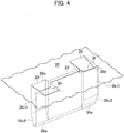
- the groove bottoms 26c, 30c of the air-guiding grooves 26, 30 can be set as described below (see Figs, 4 , 5 , and 8 ), instead of the above example ( Fig. 2 ) in which the whole thereof is made of a flat surface extending in the tire radial direction in parallel with the groove wall surface 22a, 22b of the air intake groove 22.
- the groove bottom of the air-guiding grooves 26, 30 is made of flat surfaces 26c1, 30c1 and inclined surfaces 26c2, 30c2.
- the flat surfaces 26c1, 30c1 extend from the one ends 26d, 30d of the air-guiding grooves 26, 30 to the inner side in the tire radial direction in parallel with the groove wall surfaces 22a, 22b of the air intake groove 22.
- the inclined surfaces 26c2, 30c2 are linked to the flat surfaces 26c1, 30c1 by forming an angle to reach the other ends 26e, 30e of the air-guiding grooves 26, 30.
- the inclined surfaces 26c2, 30c2 shown in Fig. 4 are replaced by concave-curved surfaces 26c3, 30c3.
- the concave-curved surfaces 26c3, 30c3 correspond to the groove wall surfaces 22a, 22b of the air intake groove 22 respectively.
- the volume of the air-guiding grooves 26, 30 can be made smaller. Therefore, degradation of rigidity of the center land section 20 by the air-guiding groove being provided can be limited.
- the one ends 26d, 30d of the air-guiding grooves 26, 30 open to the surface (tread) of the center land section 20.
- This is a factor that degrades rigidity of the tread section 12 and is also a factor that changes the heat transfer coefficient between the tread section 12 and the air AR exerting a cooling effect thereon.
- it is important how to set the aperture ratio (B/A) as a ratio of the sum (B) of orthographic projection areas of the air-guiding groove 26 and the other air-guiding groove 30 to the sum (A) of orthographic projection areas of the air introduction groove 24 and the other air introduction groove 28 on the tread of the tire 10.
- Fig. 6 the relationship between the aperture ratio (B/A) obtained from experiments and the heat transfer coefficient is shown by a graph. From the graph, the heat transfer coefficient approximately exhibits the maximum value when the aperture ratio (B/A) is from 30 to 40%. From the above result, the aperture ratio (B/A) is desirably set to 50% or less.
- the air-guiding grooves 26, 30 may have the groove bottoms 26c, 30c as a concave portion made of a concave-curved surface opposite to the groove wall surfaces 22a, 22b of the air intake groove 22.
- the air-guiding grooves 26, 30 have both groove wall surfaces 26a, 26b; 30a, 30b linked to the groove bottoms 26c, 30c respectively and the both groove wall surfaces 26a, 26b; 30a, 30b each form a crescent moon shape.
- the one ends 26d, 30d and the other ends 26e, 30e of the air-guiding grooves 26, 30 are each positioned between the surface (tread) of the center land section 20 and the groove bottom 22c of the air intake groove 22.
- the one ends 26d, 30d thereof are positioned on the outer side in the tire radial direction from the intersection position (P1) of the groove bottoms 24c, 28c of the air introduction grooves 24, 28 and the other groove wall surfaces 22b, 22a of the air intake groove 22 and the other ends 26e, 30e are positioned on the inner side in the tire radial direction from the position (P2) half the groove depth of the air intake groove 22.
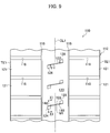
- a portion of the surface of a tread section 112 of a tire 110 according to the second embodiment is schematically shown in a state expanded on a flat surface.
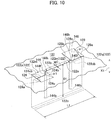
- a partial perspective view of the tread of the tire 110 according to the second embodiment is shown.
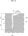
- a sectional view of a line XI-XI in Fig. 9 is shown.
- the tire 110 is made of a pneumatic tire used for large vehicles like vehicle construction machines.
- the tread section 112 of the tire 110 includes arbitrary pattern (tread pattern).
- the tread pattern shown in Fig. 9 includes a pair of circumferential grooves 116 extending in the tire circumferential direction (an up and down direction in Fig. 9 ) and a plurality of width direction grooves 118 extending in the tire width direction (a paper left and right direction in Fig. 9 ).
- the circumferential grooves 116 are each positioned on both sides of an equatorial plane CL1 of the tire 110.
- the plurality of width direction grooves 118 is arranged equidistantly to each other in the tire circumferential direction between each of the circumferential grooves 116 and each tread end TE1.
- One end of each of the width direction grooves 118 communicates with each of the circumferential grooves 116 and the other end thereof ends at each tread end TE1.
- the above tread pattern further includes a center land section 120 partitioned by both of the circumferential grooves 116 therebetween and extending in the tire circumferential direction and a block-like land section 121 partitioned by the two width direction grooves 118 adjacent to each other therebetween in the tire circumferential direction.
- the surface of the center land section 120 and that of the block-like land section 121 each define practically the tread of the tire 110.
- the tread pattern of the tread section 112 may be made of what is called a lib pattern, a lug pattern, a block pattern, or the like.
- the width direction grooves 118 may, for example, extend in a direction intersecting the tire width direction or have mutually different width dimensions.
- the tire 110 includes an air intake groove 122 provided in the tread section 112 and opening to the center land section 120 defining the tread to give off heat generated in the tread section 112 accompanying work or running of the vehicle mounted therewith.
- the air intake groove 122 extends in a direction intersecting the tire circumferential direction in the tread section 112 and has a groove width made smaller than a groove depth.
- the tire 110 opens to a tread surface side and communicates with the air intake groove 122, groove bottoms 124c, 128c are inclined so that the groove on the side of the air intake groove 122 becomes deeper, and the tire 110 has air introduction grooves 124, 128 that guide the air on the tread surface side into the air intake groove 122 accompanying the tire rotation on both end sides in the groove longitudinal direction of the air intake groove 122.
- the tire 110 includes air-guiding protrusions (air-guiding sections) 144, 146 that protrude in the groove width direction of the air intake groove 122 by being arranged on groove wall surfaces 122b, 122a of the air intake groove 122 and guide the air guided into the air intake groove 122 by the air introduction grooves 124, 128 accompanying the tire rotation to the groove bottom side of the air intake groove 122.
- the air-guiding protrusions 144, 146 are arranged on both sides in the groove longitudinal direction with respect to the center position in the groove longitudinal direction of the air intake groove in a tread surface view.
- outer ends in the tire radial direction of the air-guiding protrusions 144, 146 are positioned on the outer side in the tire radial direction from an inner end in the tire radial direction of the air intake groove 122 and inner ends in the tire radial direction of the air-guiding protrusions 144, 146 are positioned on the inner side in the tire radial direction from the position half the groove depth of the air intake groove 122.
- the air intake groove 122 is constructed of an air intake groove body section 122m positioned on the center side in the groove longitudinal direction from the air-guiding protrusions 144, 146 in the tread surface view, an air intake groove side section 122p communicating with the air introduction groove 124 on the side of the air-guiding protrusion 144 in the tread surface view, and an air intake groove side section 122q communicating with the air introduction groove 128 on the side of the air-guiding protrusion 146.
- the air introduction grooves 124, 128 are arranged on both sides in the groove longitudinal direction with respect to the center position in the groove longitudinal direction of the air intake groove in the tread surface view and extend in the tire circumferential direction so as to be in directions opposite to each other. Then, the air introduction grooves 124, 128 have a gradually shallower groove while extending in the tire circumferential direction and the bottom faces (groove bottoms) 124c, 128c of the air introduction grooves 124, 128 are an inclined surface (slope) in a flat surface shape.
- the bottom face 124c is inclined such that the groove on the side of the air intake groove side section 122p becomes deeper and the bottom face 128c is inclined such that the groove on the side of the air intake groove side section 122q becomes deeper.
- the air introduction grooves 124, 128 guide the air on the tread surface side to the air intake groove side sections 122p, 122q accompanying the tire rotation respectively.
- the air-guiding protrusion 144 is arranged on the borderline between the air intake groove body section 122m and the air intake groove side section 122p and the air-guiding protrusion 146 is arranged on the borderline between the air intake groove body section 122m and the air intake groove side section 122q.
- the height of an outer end 144h in the tire radial direction of the air-guiding protrusion 144 is set to a height of an inner end 124cb in the tire radial direction of the bottom face 124c or more and the height of an outer end 146h in the tire radial direction of the air-guiding protrusion 146 is set to a height of an inner end 128cb in the tire radial direction of the bottom face 128c or more.
- inner ends 144b, 146b in the tire radial direction of the air-guiding protrusions 144, 146 are positioned on the inner side in the tire radial direction from the position half a groove depth D1 (depth position of D1/2) of the air intake groove 122.
- the extension direction in the tire circumferential direction of the air introduction grooves 124, 128 is defined as described above, and thus, when the tire 110 rotates in one direction for work or running of the vehicle, the air introduction grooves 124, 128 are provided so as to be positioned forward and backward in the one direction respectively.
- the air introduction groove 124 serves to introduce the air (atmosphere) flowing into the air introduction groove 124 into the air intake groove side section 122p when the tire 110 rotates in the one direction.
- the air-guiding protrusion 144 serves to allow the air flowing into the air introduction groove 124 to efficiently reach a groove bottom portion of the air intake groove body section 122m by the fluid resistance in the groove longitudinal direction from the air intake groove side section 122p to the air intake groove body section 122m being increased by an outward sidewall 144f (air-guiding wall) with respect to the center position in the groove longitudinal direction of the air intake groove 122 in the position where the air-guiding protrusion 144 is formed and serves to inhibit the air flowing into the air intake groove 122 from the air intake groove side section 122p from returning to the air intake groove side section 122p.
- the other air introduction groove 128 serves as an outflow path of the air after the inside of the air intake groove 122 being fluidized.
- the air introduction groove 128 similarly serves to introduce the air (atmosphere) flowing into the other air introduction groove 128 into the air intake groove side section 122q.
- the air-guiding protrusion 146 serves to allow the air flowing into the air introduction groove 128 to efficiently reach a groove bottom portion of the air intake groove body section 122m by the fluid resistance in the groove longitudinal direction from the air intake groove side section 122q to the air intake groove body section 122m being increased by an outward sidewall 146f (air-guiding wall) with respect to the center position in the groove longitudinal direction of the air intake groove 122 in the position where the air-guiding protrusion 146 is formed and serves to inhibit the air flowing into the air intake groove 122 from the air intake groove side section 122q from returning to the air intake groove side section 122q.
- the air introduction groove 124 serves as an outflow path of the air after the inside of the air intake groove 122 being fluidized.
- the air fluidized inside the air intake groove 122 (particularly, the air fluidized at the groove bottom) serves to deprive the tread section 112 of heat.
- configuration sections such as the air intake groove 122 are arranged along the tire circumferential direction.
- a plurality of air intake grooves 122 each opens to the surface of the center land section 120 (tread of the tire 110) constituting the tread section 112.
- the plurality of air intake grooves 122 is arranged equidistantly to each other in the tire circumferential direction in parallel with each other.
- the plurality of air intake grooves 122 may be arranged at mutually different intervals or to be non-parallel to each other.
- the air intake groove 122 extends in a direction intersecting the tire circumferential direction. That is, the air intake groove 22 extends non-parallel thereto.
- An intersection angle ⁇ 1 is set so as to be in the range of 0° ⁇ ⁇ 1 ⁇ 90°, preferably 0° ⁇ ⁇ 1 ⁇ 60°.
- the air intake groove 122 illustrated has one end and the other end in the longitudinal direction thereof within the center land section 120.
- the air intake groove 122 extends within the center land section 120 and also terminates within the center land section 120.
- Both or one of both ends in the longitudinal direction of the air intake groove 122 may communicate with both or one of both of the circumferential grooves 116, but in consideration of degradation of rigidity of the center land section 120, it is desirable, like in the illustrated example, to be non-communicating.
- each of the air intake grooves 122 has a U-shaped cross-sectional shape and includes groove wall surfaces 122a, 122b made of a pair of flat surfaces opposite to each other and a groove bottom 122c linked to both of the groove wall surfaces 122a, 122b and made of a flat surface.
- a groove width W1 and a groove depth D1 (see Fig. 10 ) of each of the air intake grooves 122 are set such that the relation W1 ⁇ D1 is satisfied to limit the degradation of rigidity of the tread section 112, more specifically the degradation of rigidity of the center land section 120 caused by the air intake groove 122 being provided.
- the air introduction grooves 124, 128 each open to the surface (tread) of the center land section 120. Accordingly, the air can be taken into the air introduction grooves 124, 128 from around the tire 110.
- the air introduction groove 124 includes groove wall surfaces 124a, 124b made of a pair of flat surfaces opposite to each other and the bottom face 124c linked to both of the groove wall surfaces 124a, 124b and made of a flat surface.
- the air introduction groove 128 includes groove wall surfaces 128a, 128b made of a pair of flat surfaces opposite to each other and the bottom face 128c linked to both of the groove wall surfaces 128a, 128b and made of a flat surface.
- the bottom face 124c of the air introduction groove 124 is formed from an inclined surface inclined from the surface (tread) of the center land section 120 toward the inner side in the tire radial direction.
- the depth of groove gradually increases toward the air intake groove 122 and also both of the groove wall surfaces 124a, 124b form a right-angled triangular shape.
- the bottom face 124c may extend in a non-inclined state, but by adopting the inclined surface, a driving force larger than when forced toward the groove bottom of the air intake groove 122 can be given to the air flowing into the air intake groove 122 from the air introduction groove 124.
- the inclination angle of the inclined surface of the air introduction groove 124 that is, an inclination angle ⁇ 1 ( Fig. 10 ) with respect to the surface (tread) of the center land section 120 of the bottom face 124c is 45° or less, preferably in the range of 20° to 30°. This is because while the flow rate of the air from the air introduction grooves 124 to the air intake groove 122 increases with an increasing inclination angle ⁇ 1, if the inclination angle ⁇ 1 exceeds 45°, the flow of the air separates more easily from the bottom face 124c near the air intake groove 122, leading to a decreased flow rate of the air.
- the air introduction grooves 124, 128 and the air-guiding protrusions 144, 146 are arranged so as to be point-symmetric on both end sides in the longitudinal direction of the air intake groove 122 in the tread surface view. Therefore, the air introduction groove 128 is configured to be point-symmetric (a shape that fits perfectly after rotation of 180°) about a center M1 (see Fig. 9 ) of symmetry of the equatorial plane CL1 of the tire with respect to the air intake groove 122, which is configured in the same manner as the air introduction groove 124.
- the air having flowed into the air intake groove 122 from the air introduction grooves 124, 128 along the air-guiding protrusion 144 can efficiently be fluidized by the air-guiding protrusion 144 in a deep portion of the tread section 112 or in the neighborhood thereof.
- the groove bottom of the air intake groove 122 that is, the deep portion of the tread section 112 is cooled by heat transfer accompanying contact with the air and heat dissipation from the deep portion of the tread section 112 and lowering of the temperature of the deep portion of the tread section 112 can thereby be achieved. Therefore, the tire 110 capable of sufficiently cooling the deep portion of the tread section 112 can be implemented.
- a protrusion height H1 (see Fig. 11 ) of each of the air-guiding protrusions 144, 146 in the groove width direction of the air intake groove 122 is preferably in the range of from 15 to 75% of the groove width W1 of the air intake groove 122. Accordingly, the air can efficiently be caused to flow into the air intake groove body section 122m from the air intake groove side section 122p or the air intake groove side section 122q so that particularly the groove bottom of the air intake groove 122 can be allowed to be efficiently cooled.
- the fluid resistance between the air flowing into the air intake groove body section 122m from the air intake groove side section 122p along the air-guiding protrusion 144 and the wall surface of the air-guiding protrusion 144 increases and thus, the air having flowed in is more likely to be decelerated before reaching the groove bottom portion of the air intake groove body section 122m and the groove bottom portion of the air intake groove body section 122m cannot be efficiently cooled.
- the outer end of the air-guiding protrusion 144 is preferably arranged on the borderline between the air intake groove body section 122m and the air intake groove side section 122p.
- a depth E1 in the tire radial direction of the air-guiding protrusions 144, 146 is defined by being positioned on the inner side in the tire radial direction from the position half the groove depth D1 of the air intake groove 122 and it is further preferable that the depth E1 be in the range of from 60 to 80% of the groove depth D1 and the air-guiding protrusions 144, 146 do not reach the groove bottom 122c of the air intake groove 122.
- Figs. 10 and 11 an example in which the air-guiding protrusions 144, 146 do not reach the groove bottom 122c of the air intake groove 122 is depicted.
- an air flow at the groove bottom of the air intake groove 122 is reliably prevented from being hindered by the air-guiding protrusions 144, 146. If the depth E1 in the up and down direction of the air-guiding protrusion 144 is longer than 80% of the groove depth D1, the flow of the air flow is hindered by the inner side end in the tire radial direction of the air-guiding protrusion 144 so that a heat dissipation effect may be more likely to be weakened.
- the air is released to the side of the air intake groove 122 in a position apart from the groove bottom 122c and thus, an air flow parallel to the groove bottom 122c may arise so that a heat dissipation effect may be more likely to be weakened.
- a low protrusion site G1 whose protrusion height H1 gradually becomes lower toward the inner side in the tire radial direction may be arranged. Accordingly, a tire can be implemented that makes it easy to effectively prevent the air flow at the groove bottom 122c of the air intake groove 122 from being hindered by the low protrusion site G1, while maintaining high strength of the groove wall by the low protrusion site G1.
- Components such as grooves and air-guiding protrusions arranged in the center land section 120 may be provided in each of the block-like land sections 121, instead of the center land section 120.
- an example is taken in which the inflow of air into the air introduction grooves 124, 128 can be smoothed by the extension in the tire circumferential direction of the air introduction grooves 124, 128, but a configuration in which the direction in which the air introduction grooves 124, 128 extend is a different direction from the above direction (for example, a direction intersecting the tire circumferential direction and the tire width direction) may also be adopted.
- the air intake groove 122 may have, for example, a V-shaped cross-sectional shape.
- each of a pair of groove wall surfaces opposite to each other is made of a flat surface and the groove bottom is made of an intersection portion of both groove wall surfaces and frequently forms a linear line.
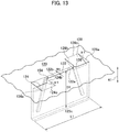
- Fig. 13 a partial perspective view of the tread of a tire according to the third embodiment is shown.
- air-guiding protrusions 154, 156 instead of the air-guiding protrusions 144, 146, that are each inclined with respect to a tire radial direction K1 are arranged so as to be positioned on the outer side in the groove longitudinal direction of the air intake groove 122 in the tread surface view with an increasing groove depth.
- the air-guiding protrusions 154, 156 are each linear when viewed from the groove wall surface side.
- the guide flow path becomes narrower toward the groove bottom, the air having flowed into the groove on the outer side in the groove longitudinal direction from the air-guiding protrusions 154, 156 in the tread surface view can be increased in flow rate toward the groove bottom. Therefore, compared with the second embodiment, heat dissipation can further be increased (compared with the second embodiment, for example, heat dissipation can be increased by a little less than 10%).
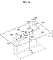
- Fig. 14 a partial perspective view of the tread of a tire according to the fourth embodiment is shown.
- air-guiding protrusions 164, 166 that are each inclined with respect to the tire radial direction K1 are arranged so as to be positioned on the outer side in the groove longitudinal direction of the air intake groove 122 in the tread surface view with an increasing groove depth.
- the air-guiding protrusions 164, 166 are curved, compared with the third embodiment, when viewed from the groove wall surface side and accordingly, the air is made easy to flow smoothly up to the inner side end in the tire radial direction (end on the groove bottom side) of the air-guiding protrusions 164, 166.
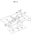
- Fig. 15 a partial perspective view of the tread of a tire according to the fifth embodiment is shown.
- air-guiding protrusions 174, 176 are arranged.
- the air-guiding protrusion 174 has a tire radial direction inner portion 174g that guides the air to the inner side in the groove longitudinal direction in the tread surface view on the inner side end in the tire radial direction (end on the groove bottom side).
- the air-guiding protrusion 176 has a tire radial direction inner portion 176g that guides the air to the inner side in the groove longitudinal direction in the tread surface view on the inner side end in the tire radial direction (end on the groove bottom side).
- the amount of air fluidized on the surface of the groove bottom increases significantly, so that the groove bottom can be cooled more efficiently compared with the fourth embodiment.
- the inventors calculated by analytical calculation the heat transfer coefficient of the entire groove bottom regarding the tire 110 according to the second embodiment by setting the protrusion height HI to 50% of the air intake groove 122 and changing the ratio (50%, 75%, 100%) of the depth E1 in the up and down direction of the air-guiding protrusions 144, 146 to the groove depth D1 of the air intake groove 122 as a parameter.
- the entire groove bottom means the groove bottom 122c and the average heat transfer coefficient of the region was calculated (this also applies in Analytical calculation example 2).
- the calculation result is shown in Fig. 16 .
- the heat transfer coefficient was calculated by analytical calculation by setting the protrusion height HI to 25% of the air intake groove 122 and changing the ratio (50%, 75%, 100%) of the guide depth to the depth of the air intake groove as a parameter.
- the calculation result is shown also in Fig. 16 .
- the inventors calculated the heat transfer coefficient of the entire groove bottom regarding a tire according to the third embodiment by setting the protrusion height H1 to 50% of the air intake groove 122 and setting the ratio of the depth E1 in the up and down direction of the air-guiding protrusions 154, 156 to the groove depth D1 of the air intake groove to 75%.
- the calculation result is shown in Fig. 17 .
- Fig. 17 In Fig.
- the inventors determined by analytical calculation the air flow on the groove wall surface of the air intake groove 122 using an example of the tire according to the second embodiment.
- a schematic diagram obtained by the present analytical calculation regarding the air flow on the groove wall surface is shown in Fig. 18 .
- the air flow in the air intake groove 122 communicating with each of both ends thereof was determined by analytical calculation for an example in which the air-guiding protrusion 144 is not formed in a tire according to the second embodiment as an example of a conventional tire.
- An obtained schematic diagram is shown in Fig. 19 .
- the air-guiding protrusions are each arranged by being inclined with respect to the tire radial direction K1 so as to be positioned on the outer side in the groove longitudinal direction of the air intake groove 122 in the tread surface view.
- the groove width in the longitudinal direction X of the air intake groove 22 of the air-guiding grooves 26, 30 may decrease with an increasing grove depth.
- the present invention provides a tire capable of sufficiently cooling a deep portion of a tread section by efficiently fluidizing the air in the deep portion of the tread section or the neighborhood thereof.
Landscapes
- Engineering & Computer Science (AREA)
- Mechanical Engineering (AREA)
- Tires In General (AREA)
Claims (13)
- Pneu (10, 110) comprenant :au moins une cannelure d'admission d'air (22, 122) ménagée dans une section de bande de roulement d'un pneu (12, 112), s'étendant dans une direction coupant une direction circonférentielle du pneu, et présentant une largeur de cannelure (W, W1) inférieure à une profondeur de cannelure (D, D1);une cannelure d'introduction d'air (24, 28, 124, 128) s'ouvrant sur un côté de surface de bande de roulement et communiquant avec la cannelure d'admission d'air (22, 122) afin d'introduire de l'air sur le côté de surface de bande de roulement dans la cannelure d'admission d'air (22, 122) accompagnant la rotation du pneu ; etune section de guidage d'air (26, 30, 144, 146, 154, 156, 164, 166, 174, 176) présentant une surface de guidage d'air (26b, 30b, 144f, 146f) qui coupe la cannelure d'admission d'air (22, 122) et qui est dirigée vers l'extérieur dans une position coupant la cannelure d'admission d'air (22, 122) relativement à une position centrale dans une direction longitudinale de cannelure de la cannelure d'admission d'air (22, 122), la surface de guidage d'air (26b, 30b, 144f, 146f) guidant un air (AR) introduit dans la cannelure d'admission d'air (22, 122) par la cannelure d'introduction d'air (24, 28, 124, 128) vers un côté inférieur de cannelure de la cannelure d'admission d'air (22, 122),dans lequel un fond de cannelure (24c, 28c) de la cannelure d'introduction d'air (24, 28) est constitué d'une surface inclinée, inclinée depuis la surface de bande de roulement vers le côté interne dans une direction radiale du pneu, l'angle d'inclinaison (α, α1) de la surface inclinée des cannelures d'introduction d'air (24, 28), relativement à la surface de bande de roulement est de 45° ou moins,dans lequel la cannelure d'introduction d'air (24, 28) communique avec une surface de paroi de cannelure (22a, 22b) d'un côté des surfaces de paroi de cannelure (22a, 22b) opposées l'une à l'autre dans la direction circonférentielle du pneu de la cannelure d'admission d'air (22),dans lequel la section de guidage d'air (26, 30) communique avec la cannelure d'admission d'air (22), communique avec la surface de paroi de cannelure (22a, 22b) de l'autre côté des surfaces de paroi de cannelure (22a, 22b) opposées l'une à l'autre dans la direction circonférentielle du pneu de la cannelure d'admission d'air (22), présente un côté extérieur dans la direction radiale du pneu sur un côté extérieur dans une direction radiale du pneu à partir d'une position de direction radiale (P1) où la cannelure d'introduction d'air (24, 28) et la cannelure d'admission d'air (22) se coupent, et présente une extrémité latérale interne dans la direction radiale du pneu sur un côté interne dans la direction radiale du pneu, depuis une position (P2) à mi-chemin d'une profondeur de cannelure (D) de la cannelure d'admission d'air (22), etdans lequel la section de guidage d'air (26, 30) comprend une cannelure de guidage d'air (26, 30) partiellement opposée à la cannelure d'introduction d'air (24, 28) au moins dans la direction circonférentielle du pneu.
- Pneu (10) selon la revendication 1, dans lequel la cannelure de guidage d'air (26, 30) présente une même profondeur de cannelure (D) que la cannelure d'admission d'air (22) et une paroi de cannelure (26c, 30c) de la cannelure de guidage d'air (26, 30) est parallèle à une surface de paroi latérale (22a, 22b) de la cannelure d'admission d'air (22) au moins partiellement dans une direction radiale.
- Pneu (10) selon la revendication 1, dans lequel une extrémité et l'autre extrémité (26d et 26e, 30d et 30e) de la cannelure de guidage d'air (26, 30) sont chacune positionnées entre une bande de roulement (20) et un fond de cannelure (22c) de la cannelure d'admission d'air (22) et constituées d'une cavité bosselée relativement à une paroi de cannelure (22a, 22b) de la cannelure d'admission d'air (22).
- Pneu (10) selon l'une quelconque des revendications 1 à 3, comprenant en outre : un autre ensemble d'une autre cannelure d'introduction d'air (28, 24) et une autre cannelure de guidage d'air (30, 26) communiquant avec la cannelure d'admission d'air (22), dans lequel l'autre cannelure d'introduction d'air (28, 24) communique avec la surface de paroi de cannelure (22a, 22b) de l'autre côté des surfaces de paroi de cannelure (22a, 22b) opposées les unes aux autres dans la direction circonférentielle de la cannelure d'admission d'air (22) et la cannelure de guidage d'air (30, 26) communique avec la surface de paroi de cannelure (22a, 22b) d'un côté dans la direction circonférentielle des surfaces de paroi de cannelure (22a, 22b) opposées l'une à l'autre dans la direction circonférentielle de la cannelure d'admission d'air (22).
- Pneu (10) selon la revendication 4, dans lequel un ensemble de la cannelure d'introduction d'air (28, 24) et de la cannelure de guidage d'air (26, 30) et l'autre ensemble de l'autre cannelure d'introduction d'air (28, 24) et de l'autre cannelure de guidage d'air (30, 26) sont chacun agencés de manière à être espacés l'un de l'autre dans une direction longitudinale de la cannelure d'admission d'air (22).
- Pneu (10) selon la revendication 1 ou 2, comprenant en outre : un autre ensemble d'une autre cannelure d'introduction d'air (28, 24) et d'une autre cannelure de guidage d'air (30, 26) communiquant avec la cannelure d'admission d'air (22), dans lequel l'autre cannelure d'introduction d'air (28, 24) coupe une autre surface de paroi de cannelure (22b, 22a) de la cannelure d'admission d'air (22), l'autre cannelure de guidage d'air (30, 26) s'ouvre sur une surface de paroi de cannelure (22b, 22a) de la cannelure d'admission d'air (22), une extrémité de la cannelure de guidage d'air (26, 30) s'ouvre sur une bande de roulement (20), et un rapport d'ouverture (B/A) comme un rapport entre une somme (B) de zones de projection orthographiques de la cannelure de guidage d'air (26, 30) et l'autre cannelure de guidage d'air (30, 26) et une somme (A) des zones de projection orthographiques de la cannelure d'introduction d'air (24, 28) et de l'autre cannelure d'introduction d'air (28, 24) sur la bande de roulement du pneu (10) est de 50 % ou moins.
- Pneu (10) selon la revendication 6, dans lequel un ensemble de la cannelure d'introduction d'air (24, 28) et de la cannelure de guidage d'air (26, 30) et l'autre ensemble de l'autre cannelure d'introduction d'air (28, 24) et de l'autre cannelure de guidage d'air (30, 26) sont chacun agencés en étant espacés l'un de l'autre dans une direction longitudinale de la cannelure d'admission d'air (22).
- Pneu (110) selon l'une quelconque des revendications 1 à 7, dans lequel la section de guidage d'air (144, 146, 154, 156, 164, 166, 174, 176) ressort dans une direction de la largeur de cannelure (W1) de la cannelure d'admission d'air (122) en étant agencée sur la paroi de cannelure de la cannelure d'admission d'air (122) et elle inclut une saillie de guidage d'air (144, 146, 154, 156, 164, 166, 174, 176) s'étendant dans la direction radiale du pneu (110) vers le fond de cannelure, et la saillie de guidage d'air (144, 146, 154, 156, 164, 166, 174, 176) guide un air guidé dans la cannelure d'admission d'air (122) par la cannelure d'introduction d'air (124, 128) accompagnant la rotation du pneu vers le côté inférieur de cannelure de la cannelure d'admission d'air (122).
- Pneu (110) selon la revendication 8, dans lequel la cannelure d'introduction d'air (124, 128) et la saillie de guidage d'air (144, 146, 154, 156, 164, 166, 174, 176) sont chacune agencées des deux côtés dans la direction longitudinale de la cannelure relativement à la position centrale dans la direction longitudinale de la cannelure de la cannelure d'admission d'air (122) dans une vue de surface de bande de roulement et la cannelure d'admission d'air (122) comprend une section de corps de cannelure d'admission d'air (122m) positionnée sur un côté central dans la direction longitudinale de la cannelure par rapport à la saillie de guidage d'air (144, 146, 154, 156, 164, 166, 174, 176) dans la vue de la surface de bande de roulement et une section latérale de cannelure d'admission d'air (122p, 122q) positionnée sur le côté extérieur dans la direction longitudinale de cannelure depuis la saillie de guidage d'air (144, 146, 154, 156, 164, 166, 174, 176) afin de communiquer avec la cannelure d'introduction d'air (124, 128).
- Pneu (110) selon la revendication 8 ou 9, dans lequel l'extrémité latérale interne dans la direction radiale du pneu de la saillie de guidage d'air (144, 146, 154, 156, 164, 166, 174, 176) n'atteint pas le fond de la cannelure de la cannelure d'admission d'air (122).
- Pneu (110) selon l'une quelconque des revendications 8 à 10, dans lequel une hauteur de saillie dans la direction de la largeur de cannelure (W1) de la saillie de guidage d'air (144, 146, 154, 156, 164, 166, 174, 176) diminue progressivement vers le côté interne dans la direction radiale du pneu.
- Pneu (110) selon l'une quelconque des revendications 8 à 11, dans lequel la saillie de guidage d'air (156) est inclinée vers le côté extérieur dans la direction longitudinale de la cannelure d'admission d'air (122) dans la vue de surface de bande de roulement vers le côté interne dans la direction radiale du pneu.
- Pneu (110) selon l'une quelconque des revendications 8 à 12, dans lequel la cannelure d'introduction d'air (124, 128) et la saillie de guidage d'air (144, 146, 154, 156, 164, 166, 174, 176) sont agencées de façon à présenter une symétrie ponctuelle dans la vue de la surface de bande de roulement des deux côtés dans la direction longitudinale de la cannelure d'admission d'air (122).
Applications Claiming Priority (3)
| Application Number | Priority Date | Filing Date | Title |
|---|---|---|---|
| JP2015055752A JP6578114B2 (ja) | 2015-03-19 | 2015-03-19 | タイヤ |
| JP2015138538 | 2015-07-10 | ||
| PCT/JP2016/058285 WO2016148178A1 (fr) | 2015-03-19 | 2016-03-16 | Pneumatique |
Publications (3)
| Publication Number | Publication Date |
|---|---|
| EP3272552A1 EP3272552A1 (fr) | 2018-01-24 |
| EP3272552A4 EP3272552A4 (fr) | 2018-03-21 |
| EP3272552B1 true EP3272552B1 (fr) | 2019-11-13 |
Family
ID=56919887
Family Applications (1)
| Application Number | Title | Priority Date | Filing Date |
|---|---|---|---|
| EP16765007.6A Active EP3272552B1 (fr) | 2015-03-19 | 2016-03-16 | Pneumatique |
Country Status (5)
| Country | Link |
|---|---|
| US (1) | US20180056730A1 (fr) |
| EP (1) | EP3272552B1 (fr) |
| CN (1) | CN107428203B (fr) |
| ES (1) | ES2770337T3 (fr) |
| WO (1) | WO2016148178A1 (fr) |
Families Citing this family (2)
| Publication number | Priority date | Publication date | Assignee | Title |
|---|---|---|---|---|
| JP6890086B2 (ja) | 2017-12-12 | 2021-06-18 | 株式会社ブリヂストン | 重荷重用タイヤ |
| JP7215900B2 (ja) * | 2018-12-27 | 2023-01-31 | Toyo Tire株式会社 | 空気入りタイヤ |
Family Cites Families (14)
| Publication number | Priority date | Publication date | Assignee | Title |
|---|---|---|---|---|
| JPH02241806A (ja) * | 1989-03-15 | 1990-09-26 | Bridgestone Corp | ギャップ差をもつサイプを有する空気入りタイヤとタイヤモールドのサイプ形成用ブレード |
| DE19651792A1 (de) * | 1996-12-12 | 1998-06-18 | Continental Ag | Fahrzeugreifen mit einer Lauffläche mit Einschnitten |
| DE502004011794D1 (de) * | 2004-03-26 | 2010-12-02 | Continental Reifen Deutschland | Fahrzeugluftreifen |
| JP4938316B2 (ja) * | 2006-01-20 | 2012-05-23 | 株式会社ブリヂストン | 建設車両用タイヤ |
| JP4943717B2 (ja) * | 2006-03-01 | 2012-05-30 | 株式会社ブリヂストン | 空気入りタイヤ |
| JP4805762B2 (ja) * | 2006-09-05 | 2011-11-02 | 株式会社ブリヂストン | 建設車両用タイヤ |
| JP5435877B2 (ja) * | 2008-01-31 | 2014-03-05 | 株式会社ブリヂストン | 空気入りタイヤ |
| JP5099914B2 (ja) * | 2008-10-03 | 2012-12-19 | 東洋ゴム工業株式会社 | 空気入りタイヤ |
| DE102009044246A1 (de) * | 2009-10-14 | 2011-05-12 | Continental Reifen Deutschland Gmbh | Laufstreifenprofil eines Fahrzeugluftreifens |
| JP5753404B2 (ja) * | 2011-02-28 | 2015-07-22 | 株式会社ブリヂストン | 建設車両用ラジアルタイヤ |
| JP5429267B2 (ja) * | 2011-11-28 | 2014-02-26 | 横浜ゴム株式会社 | 空気入りタイヤ |
| US20140116590A1 (en) * | 2012-10-26 | 2014-05-01 | The Goodyear Tire & Rubber Company | Heavy Duty Tire |
| JP5568657B1 (ja) * | 2013-03-13 | 2014-08-06 | 株式会社ブリヂストン | 空気入りタイヤ |
| JP5977696B2 (ja) * | 2013-03-13 | 2016-08-24 | 株式会社ブリヂストン | 空気入りタイヤ |
-
2016
- 2016-03-16 US US15/558,426 patent/US20180056730A1/en not_active Abandoned
- 2016-03-16 EP EP16765007.6A patent/EP3272552B1/fr active Active
- 2016-03-16 CN CN201680016602.3A patent/CN107428203B/zh active Active
- 2016-03-16 ES ES16765007T patent/ES2770337T3/es active Active
- 2016-03-16 WO PCT/JP2016/058285 patent/WO2016148178A1/fr not_active Ceased
Non-Patent Citations (1)
| Title |
|---|
| None * |
Also Published As
| Publication number | Publication date |
|---|---|
| ES2770337T3 (es) | 2020-07-01 |
| US20180056730A1 (en) | 2018-03-01 |
| CN107428203A (zh) | 2017-12-01 |
| WO2016148178A1 (fr) | 2016-09-22 |
| EP3272552A1 (fr) | 2018-01-24 |
| EP3272552A4 (fr) | 2018-03-21 |
| CN107428203B (zh) | 2019-08-27 |
Similar Documents
| Publication | Publication Date | Title |
|---|---|---|
| EP3403853B1 (fr) | Pneumatique | |
| CN105473347B (zh) | 充气轮胎 | |
| CN106852135A (zh) | 包括具有多个厚度减小的区域的可变厚度胎纹沟槽的轮胎胎面 | |
| CA2856238C (fr) | Pneumatique | |
| JP2015098325A (ja) | 空気入りタイヤ | |
| WO2014142349A1 (fr) | Pneu | |
| CN104703818A (zh) | 具有带后缘刀槽花纹的对角肋的轮胎 | |
| EP3272552B1 (fr) | Pneumatique | |
| JP2015209169A (ja) | 空気入りタイヤ | |
| US11827060B2 (en) | Heavy load tire | |
| JP2019098998A (ja) | タイヤ | |
| JP6578114B2 (ja) | タイヤ | |
| EP3505368B1 (fr) | Pneu | |
| JP5780854B2 (ja) | 空気入りタイヤ | |
| JP6735131B2 (ja) | タイヤ | |
| JP5557943B1 (ja) | 空気入りタイヤ | |
| JP2008162363A (ja) | 空気入りタイヤ | |
| EP4303035A1 (fr) | Pneu de véhicule à deux roues pour roulage sur terrain accidenté | |
| EP3312024B1 (fr) | Pneu pour un véhicule | |
| EP2871070A1 (fr) | Pneu | |
| JP2023170401A (ja) | 建設車両用タイヤ | |
| JP6706151B2 (ja) | タイヤ | |
| CN111376655A (zh) | 充气轮胎 |
Legal Events
| Date | Code | Title | Description |
|---|---|---|---|
| STAA | Information on the status of an ep patent application or granted ep patent |
Free format text: STATUS: THE INTERNATIONAL PUBLICATION HAS BEEN MADE |
|
| PUAI | Public reference made under article 153(3) epc to a published international application that has entered the european phase |
Free format text: ORIGINAL CODE: 0009012 |
|
| STAA | Information on the status of an ep patent application or granted ep patent |
Free format text: STATUS: REQUEST FOR EXAMINATION WAS MADE |
|
| 17P | Request for examination filed |
Effective date: 20171016 |
|
| AK | Designated contracting states |
Kind code of ref document: A1 Designated state(s): AL AT BE BG CH CY CZ DE DK EE ES FI FR GB GR HR HU IE IS IT LI LT LU LV MC MK MT NL NO PL PT RO RS SE SI SK SM TR |
|
| AX | Request for extension of the european patent |
Extension state: BA ME |
|
| A4 | Supplementary search report drawn up and despatched |
Effective date: 20180216 |
|
| RIC1 | Information provided on ipc code assigned before grant |
Ipc: B60C 11/03 20060101ALI20180212BHEP Ipc: B60C 11/00 20060101AFI20180212BHEP Ipc: B60C 11/12 20060101ALI20180212BHEP Ipc: B60C 11/13 20060101ALI20180212BHEP |
|
| DAV | Request for validation of the european patent (deleted) | ||
| DAX | Request for extension of the european patent (deleted) | ||
| STAA | Information on the status of an ep patent application or granted ep patent |
Free format text: STATUS: EXAMINATION IS IN PROGRESS |
|
| 17Q | First examination report despatched |
Effective date: 20190103 |
|
| GRAP | Despatch of communication of intention to grant a patent |
Free format text: ORIGINAL CODE: EPIDOSNIGR1 |
|
| STAA | Information on the status of an ep patent application or granted ep patent |
Free format text: STATUS: GRANT OF PATENT IS INTENDED |
|
| INTG | Intention to grant announced |
Effective date: 20190704 |
|
| GRAS | Grant fee paid |
Free format text: ORIGINAL CODE: EPIDOSNIGR3 |
|
| GRAA | (expected) grant |
Free format text: ORIGINAL CODE: 0009210 |
|
| STAA | Information on the status of an ep patent application or granted ep patent |
Free format text: STATUS: THE PATENT HAS BEEN GRANTED |
|
| AK | Designated contracting states |
Kind code of ref document: B1 Designated state(s): AL AT BE BG CH CY CZ DE DK EE ES FI FR GB GR HR HU IE IS IT LI LT LU LV MC MK MT NL NO PL PT RO RS SE SI SK SM TR |
|
| REG | Reference to a national code |
Ref country code: CH Ref legal event code: EP Ref country code: AT Ref legal event code: REF Ref document number: 1201277 Country of ref document: AT Kind code of ref document: T Effective date: 20191115 |
|
| REG | Reference to a national code |
Ref country code: DE Ref legal event code: R096 Ref document number: 602016024351 Country of ref document: DE |
|
| REG | Reference to a national code |
Ref country code: IE Ref legal event code: FG4D |
|
| REG | Reference to a national code |
Ref country code: NL Ref legal event code: MP Effective date: 20191113 |
|
| REG | Reference to a national code |
Ref country code: LT Ref legal event code: MG4D |
|
| PG25 | Lapsed in a contracting state [announced via postgrant information from national office to epo] |
Ref country code: FI Free format text: LAPSE BECAUSE OF FAILURE TO SUBMIT A TRANSLATION OF THE DESCRIPTION OR TO PAY THE FEE WITHIN THE PRESCRIBED TIME-LIMIT Effective date: 20191113 Ref country code: GR Free format text: LAPSE BECAUSE OF FAILURE TO SUBMIT A TRANSLATION OF THE DESCRIPTION OR TO PAY THE FEE WITHIN THE PRESCRIBED TIME-LIMIT Effective date: 20200214 Ref country code: NO Free format text: LAPSE BECAUSE OF FAILURE TO SUBMIT A TRANSLATION OF THE DESCRIPTION OR TO PAY THE FEE WITHIN THE PRESCRIBED TIME-LIMIT Effective date: 20200213 Ref country code: PT Free format text: LAPSE BECAUSE OF FAILURE TO SUBMIT A TRANSLATION OF THE DESCRIPTION OR TO PAY THE FEE WITHIN THE PRESCRIBED TIME-LIMIT Effective date: 20200313 Ref country code: BG Free format text: LAPSE BECAUSE OF FAILURE TO SUBMIT A TRANSLATION OF THE DESCRIPTION OR TO PAY THE FEE WITHIN THE PRESCRIBED TIME-LIMIT Effective date: 20200213 Ref country code: SE Free format text: LAPSE BECAUSE OF FAILURE TO SUBMIT A TRANSLATION OF THE DESCRIPTION OR TO PAY THE FEE WITHIN THE PRESCRIBED TIME-LIMIT Effective date: 20191113 Ref country code: LV Free format text: LAPSE BECAUSE OF FAILURE TO SUBMIT A TRANSLATION OF THE DESCRIPTION OR TO PAY THE FEE WITHIN THE PRESCRIBED TIME-LIMIT Effective date: 20191113 Ref country code: NL Free format text: LAPSE BECAUSE OF FAILURE TO SUBMIT A TRANSLATION OF THE DESCRIPTION OR TO PAY THE FEE WITHIN THE PRESCRIBED TIME-LIMIT Effective date: 20191113 Ref country code: PL Free format text: LAPSE BECAUSE OF FAILURE TO SUBMIT A TRANSLATION OF THE DESCRIPTION OR TO PAY THE FEE WITHIN THE PRESCRIBED TIME-LIMIT Effective date: 20191113 Ref country code: LT Free format text: LAPSE BECAUSE OF FAILURE TO SUBMIT A TRANSLATION OF THE DESCRIPTION OR TO PAY THE FEE WITHIN THE PRESCRIBED TIME-LIMIT Effective date: 20191113 |
|
| PG25 | Lapsed in a contracting state [announced via postgrant information from national office to epo] |
Ref country code: IS Free format text: LAPSE BECAUSE OF FAILURE TO SUBMIT A TRANSLATION OF THE DESCRIPTION OR TO PAY THE FEE WITHIN THE PRESCRIBED TIME-LIMIT Effective date: 20200313 Ref country code: HR Free format text: LAPSE BECAUSE OF FAILURE TO SUBMIT A TRANSLATION OF THE DESCRIPTION OR TO PAY THE FEE WITHIN THE PRESCRIBED TIME-LIMIT Effective date: 20191113 Ref country code: RS Free format text: LAPSE BECAUSE OF FAILURE TO SUBMIT A TRANSLATION OF THE DESCRIPTION OR TO PAY THE FEE WITHIN THE PRESCRIBED TIME-LIMIT Effective date: 20191113 |
|
| PG25 | Lapsed in a contracting state [announced via postgrant information from national office to epo] |
Ref country code: AL Free format text: LAPSE BECAUSE OF FAILURE TO SUBMIT A TRANSLATION OF THE DESCRIPTION OR TO PAY THE FEE WITHIN THE PRESCRIBED TIME-LIMIT Effective date: 20191113 |
|
| REG | Reference to a national code |
Ref country code: ES Ref legal event code: FG2A Ref document number: 2770337 Country of ref document: ES Kind code of ref document: T3 Effective date: 20200701 |
|
| PG25 | Lapsed in a contracting state [announced via postgrant information from national office to epo] |
Ref country code: DK Free format text: LAPSE BECAUSE OF FAILURE TO SUBMIT A TRANSLATION OF THE DESCRIPTION OR TO PAY THE FEE WITHIN THE PRESCRIBED TIME-LIMIT Effective date: 20191113 Ref country code: EE Free format text: LAPSE BECAUSE OF FAILURE TO SUBMIT A TRANSLATION OF THE DESCRIPTION OR TO PAY THE FEE WITHIN THE PRESCRIBED TIME-LIMIT Effective date: 20191113 Ref country code: CZ Free format text: LAPSE BECAUSE OF FAILURE TO SUBMIT A TRANSLATION OF THE DESCRIPTION OR TO PAY THE FEE WITHIN THE PRESCRIBED TIME-LIMIT Effective date: 20191113 Ref country code: RO Free format text: LAPSE BECAUSE OF FAILURE TO SUBMIT A TRANSLATION OF THE DESCRIPTION OR TO PAY THE FEE WITHIN THE PRESCRIBED TIME-LIMIT Effective date: 20191113 |
|
| REG | Reference to a national code |
Ref country code: DE Ref legal event code: R097 Ref document number: 602016024351 Country of ref document: DE |
|
| REG | Reference to a national code |
Ref country code: AT Ref legal event code: MK05 Ref document number: 1201277 Country of ref document: AT Kind code of ref document: T Effective date: 20191113 |
|
| PG25 | Lapsed in a contracting state [announced via postgrant information from national office to epo] |
Ref country code: SM Free format text: LAPSE BECAUSE OF FAILURE TO SUBMIT A TRANSLATION OF THE DESCRIPTION OR TO PAY THE FEE WITHIN THE PRESCRIBED TIME-LIMIT Effective date: 20191113 Ref country code: SK Free format text: LAPSE BECAUSE OF FAILURE TO SUBMIT A TRANSLATION OF THE DESCRIPTION OR TO PAY THE FEE WITHIN THE PRESCRIBED TIME-LIMIT Effective date: 20191113 |
|
| PLBE | No opposition filed within time limit |
Free format text: ORIGINAL CODE: 0009261 |
|
| STAA | Information on the status of an ep patent application or granted ep patent |
Free format text: STATUS: NO OPPOSITION FILED WITHIN TIME LIMIT |
|
| REG | Reference to a national code |
Ref country code: DE Ref legal event code: R119 Ref document number: 602016024351 Country of ref document: DE |
|
| 26N | No opposition filed |
Effective date: 20200814 |
|
| PG25 | Lapsed in a contracting state [announced via postgrant information from national office to epo] |
Ref country code: MC Free format text: LAPSE BECAUSE OF FAILURE TO SUBMIT A TRANSLATION OF THE DESCRIPTION OR TO PAY THE FEE WITHIN THE PRESCRIBED TIME-LIMIT Effective date: 20191113 |
|
| REG | Reference to a national code |
Ref country code: CH Ref legal event code: PL |
|
| PG25 | Lapsed in a contracting state [announced via postgrant information from national office to epo] |
Ref country code: AT Free format text: LAPSE BECAUSE OF FAILURE TO SUBMIT A TRANSLATION OF THE DESCRIPTION OR TO PAY THE FEE WITHIN THE PRESCRIBED TIME-LIMIT Effective date: 20191113 Ref country code: SI Free format text: LAPSE BECAUSE OF FAILURE TO SUBMIT A TRANSLATION OF THE DESCRIPTION OR TO PAY THE FEE WITHIN THE PRESCRIBED TIME-LIMIT Effective date: 20191113 |
|
| REG | Reference to a national code |
Ref country code: BE Ref legal event code: MM Effective date: 20200331 |
|
| PG25 | Lapsed in a contracting state [announced via postgrant information from national office to epo] |
Ref country code: LU Free format text: LAPSE BECAUSE OF NON-PAYMENT OF DUE FEES Effective date: 20200316 |
|
| PG25 | Lapsed in a contracting state [announced via postgrant information from national office to epo] |
Ref country code: DE Free format text: LAPSE BECAUSE OF NON-PAYMENT OF DUE FEES Effective date: 20201001 Ref country code: LI Free format text: LAPSE BECAUSE OF NON-PAYMENT OF DUE FEES Effective date: 20200331 Ref country code: CH Free format text: LAPSE BECAUSE OF NON-PAYMENT OF DUE FEES Effective date: 20200331 Ref country code: IT Free format text: LAPSE BECAUSE OF FAILURE TO SUBMIT A TRANSLATION OF THE DESCRIPTION OR TO PAY THE FEE WITHIN THE PRESCRIBED TIME-LIMIT Effective date: 20191113 Ref country code: IE Free format text: LAPSE BECAUSE OF NON-PAYMENT OF DUE FEES Effective date: 20200316 |
|
| PG25 | Lapsed in a contracting state [announced via postgrant information from national office to epo] |
Ref country code: BE Free format text: LAPSE BECAUSE OF NON-PAYMENT OF DUE FEES Effective date: 20200331 |
|
| GBPC | Gb: european patent ceased through non-payment of renewal fee |
Effective date: 20200316 |
|
| PG25 | Lapsed in a contracting state [announced via postgrant information from national office to epo] |
Ref country code: GB Free format text: LAPSE BECAUSE OF NON-PAYMENT OF DUE FEES Effective date: 20200316 |
|
| PG25 | Lapsed in a contracting state [announced via postgrant information from national office to epo] |
Ref country code: TR Free format text: LAPSE BECAUSE OF FAILURE TO SUBMIT A TRANSLATION OF THE DESCRIPTION OR TO PAY THE FEE WITHIN THE PRESCRIBED TIME-LIMIT Effective date: 20191113 Ref country code: MT Free format text: LAPSE BECAUSE OF FAILURE TO SUBMIT A TRANSLATION OF THE DESCRIPTION OR TO PAY THE FEE WITHIN THE PRESCRIBED TIME-LIMIT Effective date: 20191113 Ref country code: CY Free format text: LAPSE BECAUSE OF FAILURE TO SUBMIT A TRANSLATION OF THE DESCRIPTION OR TO PAY THE FEE WITHIN THE PRESCRIBED TIME-LIMIT Effective date: 20191113 |
|
| PG25 | Lapsed in a contracting state [announced via postgrant information from national office to epo] |
Ref country code: MK Free format text: LAPSE BECAUSE OF FAILURE TO SUBMIT A TRANSLATION OF THE DESCRIPTION OR TO PAY THE FEE WITHIN THE PRESCRIBED TIME-LIMIT Effective date: 20191113 |
|
| P01 | Opt-out of the competence of the unified patent court (upc) registered |
Effective date: 20230531 |
|
| PGFP | Annual fee paid to national office [announced via postgrant information from national office to epo] |
Ref country code: FR Payment date: 20250325 Year of fee payment: 10 |
|
| PGFP | Annual fee paid to national office [announced via postgrant information from national office to epo] |
Ref country code: ES Payment date: 20250429 Year of fee payment: 10 |