WO2016148178A1 - Pneumatique - Google Patents
Pneumatique Download PDFInfo
- Publication number
- WO2016148178A1 WO2016148178A1 PCT/JP2016/058285 JP2016058285W WO2016148178A1 WO 2016148178 A1 WO2016148178 A1 WO 2016148178A1 JP 2016058285 W JP2016058285 W JP 2016058285W WO 2016148178 A1 WO2016148178 A1 WO 2016148178A1
- Authority
- WO
- WIPO (PCT)
- Prior art keywords
- groove
- air
- receiving groove
- tire
- air receiving
- Prior art date
- Legal status (The legal status is an assumption and is not a legal conclusion. Google has not performed a legal analysis and makes no representation as to the accuracy of the status listed.)
- Ceased
Links
Images




Classifications
-
- B—PERFORMING OPERATIONS; TRANSPORTING
- B60—VEHICLES IN GENERAL
- B60C—VEHICLE TYRES; TYRE INFLATION; TYRE CHANGING; CONNECTING VALVES TO INFLATABLE ELASTIC BODIES IN GENERAL; DEVICES OR ARRANGEMENTS RELATED TO TYRES
- B60C11/00—Tyre tread bands; Tread patterns; Anti-skid inserts
- B60C11/03—Tread patterns
- B60C11/0311—Patterns comprising tread lugs arranged parallel or oblique to the axis of rotation
-
- B—PERFORMING OPERATIONS; TRANSPORTING
- B60—VEHICLES IN GENERAL
- B60C—VEHICLE TYRES; TYRE INFLATION; TYRE CHANGING; CONNECTING VALVES TO INFLATABLE ELASTIC BODIES IN GENERAL; DEVICES OR ARRANGEMENTS RELATED TO TYRES
- B60C11/00—Tyre tread bands; Tread patterns; Anti-skid inserts
- B60C11/03—Tread patterns
- B60C11/13—Tread patterns characterised by the groove cross-section, e.g. for buttressing or preventing stone-trapping
- B60C11/1307—Tread patterns characterised by the groove cross-section, e.g. for buttressing or preventing stone-trapping with special features of the groove walls
-
- B—PERFORMING OPERATIONS; TRANSPORTING
- B60—VEHICLES IN GENERAL
- B60C—VEHICLE TYRES; TYRE INFLATION; TYRE CHANGING; CONNECTING VALVES TO INFLATABLE ELASTIC BODIES IN GENERAL; DEVICES OR ARRANGEMENTS RELATED TO TYRES
- B60C11/00—Tyre tread bands; Tread patterns; Anti-skid inserts
- B60C11/03—Tread patterns
- B60C11/032—Patterns comprising isolated recesses
-
- B—PERFORMING OPERATIONS; TRANSPORTING
- B60—VEHICLES IN GENERAL
- B60C—VEHICLE TYRES; TYRE INFLATION; TYRE CHANGING; CONNECTING VALVES TO INFLATABLE ELASTIC BODIES IN GENERAL; DEVICES OR ARRANGEMENTS RELATED TO TYRES
- B60C11/00—Tyre tread bands; Tread patterns; Anti-skid inserts
- B60C11/03—Tread patterns
- B60C2011/0337—Tread patterns characterised by particular design features of the pattern
- B60C2011/0339—Grooves
- B60C2011/0358—Lateral grooves, i.e. having an angle of 45 to 90 degees to the equatorial plane
- B60C2011/0365—Lateral grooves, i.e. having an angle of 45 to 90 degees to the equatorial plane characterised by width
-
- B—PERFORMING OPERATIONS; TRANSPORTING
- B60—VEHICLES IN GENERAL
- B60C—VEHICLE TYRES; TYRE INFLATION; TYRE CHANGING; CONNECTING VALVES TO INFLATABLE ELASTIC BODIES IN GENERAL; DEVICES OR ARRANGEMENTS RELATED TO TYRES
- B60C11/00—Tyre tread bands; Tread patterns; Anti-skid inserts
- B60C11/03—Tread patterns
- B60C2011/0337—Tread patterns characterised by particular design features of the pattern
- B60C2011/0339—Grooves
- B60C2011/0358—Lateral grooves, i.e. having an angle of 45 to 90 degees to the equatorial plane
- B60C2011/0367—Lateral grooves, i.e. having an angle of 45 to 90 degees to the equatorial plane characterised by depth
-
- B—PERFORMING OPERATIONS; TRANSPORTING
- B60—VEHICLES IN GENERAL
- B60C—VEHICLE TYRES; TYRE INFLATION; TYRE CHANGING; CONNECTING VALVES TO INFLATABLE ELASTIC BODIES IN GENERAL; DEVICES OR ARRANGEMENTS RELATED TO TYRES
- B60C11/00—Tyre tread bands; Tread patterns; Anti-skid inserts
- B60C11/03—Tread patterns
- B60C2011/0337—Tread patterns characterised by particular design features of the pattern
- B60C2011/0339—Grooves
- B60C2011/0358—Lateral grooves, i.e. having an angle of 45 to 90 degees to the equatorial plane
- B60C2011/0367—Lateral grooves, i.e. having an angle of 45 to 90 degees to the equatorial plane characterised by depth
- B60C2011/0369—Lateral grooves, i.e. having an angle of 45 to 90 degees to the equatorial plane characterised by depth with varying depth of the groove
-
- B—PERFORMING OPERATIONS; TRANSPORTING
- B60—VEHICLES IN GENERAL
- B60C—VEHICLE TYRES; TYRE INFLATION; TYRE CHANGING; CONNECTING VALVES TO INFLATABLE ELASTIC BODIES IN GENERAL; DEVICES OR ARRANGEMENTS RELATED TO TYRES
- B60C11/00—Tyre tread bands; Tread patterns; Anti-skid inserts
- B60C11/03—Tread patterns
- B60C2011/0337—Tread patterns characterised by particular design features of the pattern
- B60C2011/0339—Grooves
- B60C2011/0381—Blind or isolated grooves
- B60C2011/0383—Blind or isolated grooves at the centre of the tread
-
- B—PERFORMING OPERATIONS; TRANSPORTING
- B60—VEHICLES IN GENERAL
- B60C—VEHICLE TYRES; TYRE INFLATION; TYRE CHANGING; CONNECTING VALVES TO INFLATABLE ELASTIC BODIES IN GENERAL; DEVICES OR ARRANGEMENTS RELATED TO TYRES
- B60C2200/00—Tyres specially adapted for particular applications
- B60C2200/06—Tyres specially adapted for particular applications for heavy duty vehicles
- B60C2200/065—Tyres specially adapted for particular applications for heavy duty vehicles for construction vehicles
Definitions
- the present invention relates to a tire, and more particularly to a tire suitable for mounting on a large vehicle, particularly a construction vehicle.
- a pneumatic tire used for a large vehicle such as a vehicle construction machine has a tread portion that is thicker than tires of other vehicles. For this reason, there exists a problem that the temperature in the tread part of the tire which generate
- air introduced into the air receiving groove through the air introducing groove and received air flows in the longitudinal direction in the air receiving groove, and in the meantime, near the groove bottom portion of the air receiving groove, and thus the The vicinity of the deep portion of the tread portion is cooled.
- the air introduced into the air receiving groove may flow not in the vicinity of the bottom of the air receiving groove but in a relatively shallow area below the open surface of the air receiving groove. For this reason, there may be a case where the deep portion of the tread portion having a relatively high temperature is not sufficiently cooled.
- the present invention has been made in view of the above problems, and it is an object of the present invention to provide a tire capable of sufficiently cooling the deep portion of the tread portion by efficiently flowing air in the deep portion of the tread portion or in the vicinity thereof.
- the tire according to the first aspect of the present invention is provided on the tire tread portion, extends in a direction intersecting the tire circumferential direction and has a groove width smaller than the groove depth, and on the tread surface side.
- An air inlet groove that opens and communicates with the air receiving groove and introduces air on the tread surface side to the air receiving groove as the tire rotates, and air reception at a position that intersects the air receiving groove and intersects the air receiving groove.
- An air guide having an air guide surface that is outward with respect to the center position in the longitudinal direction of the groove, and that guides air introduced into the air receiving groove by the air introduction groove to the groove bottom side of the air receiving groove.
- the air introduction groove communicates with the groove wall surface on one side of the groove wall surface facing the tire circumferential direction of the air receiving groove.
- the air guide portion communicates with the air receiving groove, communicates with the groove wall surface on the other side of the groove wall surface facing the tire circumferential direction of the air receiving groove, and the outer end in the tire radial direction intersects the air introducing groove and the air receiving groove.
- the outer end of the tire in the radial direction of the tire in the radial direction of the tire, the inner end of the tire in the radial direction of the tire is inward of the tire in the radial direction of the half of the groove depth of the air receiving groove, and the air introduction groove and at least a portion in the tire circumferential direction
- the air guide grooves are opposed to each other.
- the air guide portion is disposed on the groove wall of the air receiving groove, protrudes in the groove width direction of the air receiving groove, and extends in the tire radial direction toward the groove bottom. It is a guide protrusion.
- the air guide protrusion guides the air guided to the air receiving groove by the air introduction groove as the tire rotates to the groove bottom side of the air receiving groove.
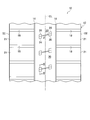
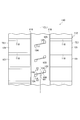
- FIG. 1 is a schematic view showing a part of the tread surface of the tire according to the first embodiment in a state where it is developed on a flat surface.
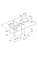
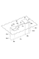
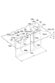
- FIG. 2 shows an air receiving groove for air that opens to the tread of the tire according to the first embodiment, a set of air introducing grooves and air guiding grooves that communicate with the air receiving groove, and another set of other air introducing grooves. It is a perspective view which shows an air guide groove.
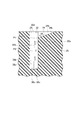
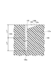
- FIG. 3 is a cross-sectional view taken along line III-III in FIG.
- FIG. 4 is a schematic perspective view showing a modification of the air guide groove according to the first embodiment.
- FIG. 5 is a schematic partial perspective view showing another modification of the air guide groove according to the first embodiment.
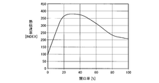
- FIG. 6 shows the sum of the orthographic projection areas of the air guide groove and other air guide grooves (A) with respect to the sum (A) of the orthographic projection areas of the air introduction groove and other air introduction grooves on the tread of the tire according to the first embodiment. It is a graph which shows the relationship between the aperture ratio (B / A) which is a ratio of B), and the heat transfer rate of the air in an air receiving groove.
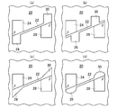
- FIGS. 7A to 7D are schematic orthographic views showing examples of the positional relationship between the two air introduction grooves and the air guide grooves of the tire according to the first embodiment.
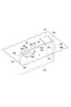
- FIG. 8 is a perspective view showing still another modification of the air guide groove according to the first embodiment of the present invention.
- FIG. 9 is a schematic view showing a part of the tread surface of the tire according to the second embodiment in a state where it is developed on a flat surface.
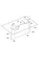
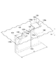
- FIG. 10 is a partial perspective view of a tread surface of a tire according to the second embodiment.
- 11 is a cross-sectional view taken along line XI-XI in FIG.
- FIG. 12 is a cross-sectional view showing a modification taken along line XI-XI in FIG.
- FIG. 13 is a partial perspective view of a tread surface of a tire according to the third embodiment.
- FIG. 14 is a partial perspective view of a tread surface of a tire according to the fourth embodiment.
- FIG. 15 is a partial perspective view of a tread surface of a tire according to the fifth embodiment.
- FIG. 10 is a partial perspective view of a tread surface of a tire according to the second embodiment.
- 11 is a cross-sectional view taken along line XI-XI in FIG.
- FIG. 12 is a cross-section
- FIG. 16 is a graph showing a calculation result in the analysis calculation example 1.
- FIG. 17 is a graph showing a calculation result in the analysis calculation example 2.
- FIG. 18 is an analysis calculation example 3 and is a graph showing calculation results in the example.
- FIG. 19 is a graph showing a calculation result in the conventional example in the analysis calculation example 3.
- the tire 10 is not limited to the application target, but is typically a pneumatic tire used for a large vehicle such as a vehicle construction machine.
- the tread portion 12 of the tire 10 has an arbitrary pattern (tread pattern).
- the tread pattern shown in FIG. 1 includes a pair of circumferential grooves 16 extending in the tire circumferential direction (up and down direction in FIG. 1) and a plurality of width direction grooves 18 extending in the tire width direction (left and right direction in FIG. 1). Both circumferential grooves 16 are located on both sides of the equatorial plane CL of the tire 10. Further, the plurality of widthwise grooves 18 are arranged at equal intervals in the tire circumferential direction between each circumferential groove 16 and each tread end TE. Each widthwise groove 18 communicates with each circumferential groove 16 at one end, and the other end ends at each tread end TE.
- the tread pattern is defined between the central land portion 20 extending in the tire circumferential direction defined between the circumferential grooves 16 and the two widthwise grooves 18 adjacent to each other in the tire circumferential direction. And a block-shaped land portion 21.
- the surfaces of the central land portion 20 and the block-shaped land portion 21 substantially define the tread surface of the tire 10, respectively.
- the tread pattern of the tread portion 12 may be a so-called rib pattern, rug pattern, block pattern, or the like.
- channel 18 may extend in the direction which cross
- the tire 10 is opened to the surface of the central land portion 20 that defines the tread surface provided in the tread portion 12 to release heat generated in the tread portion 12 in accordance with the work or running of the vehicle on which the tire 10 is mounted.
- Air introduction groove 28 and another air guide groove (air guide part) 30 may be provided in each block-shaped land portion 21 instead of the illustrated example.
- the air introduction grooves 24 and 28 are provided so as to be positioned forward and rearward in the one direction when the tire 10 rotates in one direction for the vehicle to work or travel, respectively.
- the air introduction groove 24 functions to introduce air (atmosphere) flowing into the air introduction groove 24 into the air reception groove 22 when the tire 10 rotates in the one direction, and the air reception groove 22 is introduced into this.
- the air guide groove 26 serves to receive air and guides the air introduced into the air receiving groove 22 toward the groove bottom of the air receiving groove 22. At this time, the other air introduction groove 28 functions as an air outflow path after flowing in the air receiving groove 22.
- another air introduction groove 28 serves to introduce the air flowing into the air reception groove 22, and the air guide groove 30 is introduced into the air reception groove 22.
- the air is guided toward the groove bottom of the air receiving groove 22.
- the air introduction groove 24 functions as an air outflow path after flowing in the air receiving groove 22.
- the air flowing through the air receiving groove 22 functions to take heat away from the tread portion 12 during the flow.
- Each of the plurality of air receiving grooves 22 is open to the surface of the central land portion 20 constituting the tread portion 12 (the tread surface of the tire 10).
- the plurality of air receiving grooves 22 are arranged in parallel to each other at equal intervals in the tire circumferential direction.
- the plurality of air receiving grooves 22 can be arranged at different intervals or non-parallel to each other.
- the air receiving groove 22 extends in a direction intersecting the tire circumferential direction with respect to the tire circumferential direction. That is, it extends non-parallel to the tire circumferential direction.
- the crossing angle ⁇ is set in a range of 0 ° ⁇ ⁇ 90 °, and preferably in a range of 0 ° ⁇ ⁇ 60 °.
- the air receiving groove 22 shown in the figure has one end and the other end in the longitudinal direction in the central land portion 20.
- the air receiving groove 22 extends in the central land portion 20 and terminates in the central land portion 20.
- the air receiving groove 22 may be communicated with both or one of the circumferential grooves 16 at both or one of the both ends in the longitudinal direction thereof, but considering the decrease in rigidity of the central land portion 20, It is desirable not to communicate as in the illustrated example.
- each air receiving groove 22 is connected to a groove wall surface 22a, 22b composed of a U-shaped cross-sectional shape and a pair of opposed flat surfaces defining the U-shaped cross section, and both the groove wall surfaces 22a, 22b. And a groove bottom 22c made of a flat surface.
- the air receiving groove 22 may have, for example, a V-shaped cross section instead of the illustrated example.
- the pair of groove wall surfaces facing each other is a flat surface
- the groove bottom is a crossing portion of both groove wall surfaces and has a straight line shape.
- Two sets of air introduction grooves and air guide grooves which are one set of air introduction groove 24 and air guide groove 26, and another set of other air introduction grooves 28 and air guide grooves 30 are respectively the air receiving grooves.
- the air receiving grooves 22 are disposed at both ends in the longitudinal direction.
- only one of the two sets (for example, one set of the air introduction groove 24 and the air guide groove 26) can be provided on either one of the both ends of the air receiving groove 22.
- only one of the two sets (for example, one set of air introduction groove 24 and air guide groove 26) is provided at one end of the air receiving groove 22, and the other is provided at the other end of the air receiving groove 22. Only the air introduction groove 28 can be provided.
- the air introduction grooves 24 and 28 are open to the surface (tread surface) of the central land portion 20, respectively.
- air can be taken into the air introduction grooves 24 and 28 from the periphery of the tire 10.
- the air introduction grooves 24 and 28 each extend in an arbitrary direction, preferably in the tire circumferential direction. Thereby, smooth inflow of the air into the air introduction grooves 24 and 28 can be achieved.
- the air introduction grooves 24 and 28 communicate with the air reception groove 22 at one of the groove wall surfaces 22a and 22b defining the groove width W (FIG. 2) of the air reception groove 22 and the other 22b, respectively.
- the air receiving groove opens. Accordingly, the air can be taken in and the air can be introduced into the air receiving groove 22 when the tire 10 is rotated in the one direction and in the opposite direction.
- One of the air introduction grooves 24 includes a U-shaped cross-sectional shape, a pair of opposed flat surfaces that define the U-shaped cross section, and groove surfaces 24a and 24b that are opposed to each other, and a groove bottom 24c that is formed of a flat surface that is continuous with both of these groove walls.
- the groove bottom 24 c intersects one groove wall surface 22 a of the air receiving groove 22.
- the other air introduction groove 28 also has a U-shaped cross-sectional shape similar to that of the air introduction groove 24 and a pair of opposed flat surfaces that define the U-shaped transverse wall surface 28a, 28b, and both of these groove wall surfaces 28a, 28b.
- the groove bottom 28 c is a flat surface, and the groove bottom 28 c intersects the other groove wall surface 22 b of the air receiving groove 22.
- Each of the air introduction grooves 24 and 28 may have, for example, a V-shaped cross section instead of the illustrated example.
- a pair of groove wall surfaces facing each other is a flat surface, and the groove bottom is an intersection of both groove wall surfaces, and has a linear shape.
- the groove bottom 24c of the air introduction groove 24 and the groove bottom 28c of the air introduction groove 28 are respectively inclined surfaces inclined from the surface (tread surface) of the central land portion 20 toward the inside in the tire radial direction. For this reason, the groove depth gradually increases toward the air receiving groove 22, and both the groove wall surfaces 24a and 24b and the both groove wall surfaces 28a and 28b have a right triangle shape. Each of the groove bottom 24c and the groove bottom 28c may extend in a non-inclined state. However, when the groove bottom 24c and the groove bottom 28c are formed as the inclined surface, the air introduction groove 24 is compared with the case where the groove bottom 24c is in a non-inclined state. To the air guide groove 26 can be given more propulsive power forcing it toward the groove bottom of the air receiving groove 22.
- the inclination angle ⁇ of the inclined surfaces of the air introduction grooves 24, 28, that is, the inclination angle ⁇ (FIG. 2) with respect to the surface (tread surface) of the central land portion 20 of the groove bottoms 24c, 28c is 45 ° or less, preferably 20 ° -30 °. It is desirable to be in the range. This is because the flow rate of the air from the air introduction grooves 24 and 28 to the air receiving groove 22 increases as the inclination angle ⁇ increases, but in the vicinity of the air receiving groove 22 when the inclination angle ⁇ exceeds 45 °. This is because the air flow is easily separated from the groove bottoms 24c and 28c, and the flow rate of the air is reduced.
- the air guide groove 26 has a U-shaped cross-sectional shape, a groove wall surface 26a, 26b composed of a pair of opposed flat surfaces defining the U-shaped cross section, and a groove bottom 26c composed of a flat surface connected to both the groove wall surfaces.
- the other air guide grooves 30 are formed on the groove wall surfaces 30a and 30b formed of a U-shaped cross-sectional shape similar to the air guide groove 26 and a pair of opposed flat surfaces that define the U-shaped cross section, and both the groove wall surfaces.
- a groove bottom 30c formed of a flat surface.
- Each of the air guide grooves 26 and 30 may have, for example, a V-shaped cross section instead of the illustrated example (see FIG. 7C).
- a pair of groove wall surfaces facing each other is a flat surface
- the groove bottom is an intersection of both groove wall surfaces.
- the air guide grooves 26 and 30 are open to the groove wall surface 22b and the groove wall surface 22a on the other side in the circumferential direction of the air receiving groove 22, respectively, and extend in the tire radial direction.
- the air guide grooves 26 and 30 are groove wall surfaces that are outward with respect to the center position in the longitudinal direction of the air receiving groove 22 at a position intersecting the other groove wall surface 22b of the air receiving groove 22 or the one groove wall surface 22a. Air guide surfaces) 26b and 30b. Therefore, the air introduced into the air receiving groove 22 has a smaller fluid resistance than the case where only the air receiving groove 22 is formed at the position where the air guide grooves 26 and 30 are formed, and the air receiving groove 22 It can guide toward the groove bottom 22c of 22.
- the center position in the longitudinal direction of the air receiving groove 22 refers to, for example, a range of ⁇ 5% of the longitudinal length L of the air receiving groove 22 from the center in the longitudinal direction of the air receiving groove 22.
- the air guide groove 26 has one end (outer end in the figure) 26d and the other end (inner end in the figure) 26e in the tire radial direction.
- One end 26d and the other end 26e of the air guide groove 26 are respectively located on the outer side in the tire radial direction from the intersection position P1 (FIG. 3) between the groove bottom 24c of the air introduction groove 24 and one groove wall surface 22a of the air receiving groove 22. It is on the inner side in the tire radial direction from the position P2 (FIG. 3) which is half the groove depth of the air receiving groove 22.
- one end 26 d of the air guide groove 26 is open to the surface (tread surface) of the central land portion 20, and the other end 26 e has the same groove depth as the groove bottom 22 c of the air receiving groove 22.
- the air guide groove 30 also has one end (outer end) 30d and the other end (inner end) 30e in the tire radial direction (FIG. 2).
- the one end 30d and the other end 30e (FIG. 2) of the air guide groove 30 are also more tires than the intersection position (P1) between the groove bottom 28c of the air introduction groove 28 and the other groove wall surface 22b of the air receiving groove 22, respectively. It exists in the tire radial direction inner side than the position (P2) of the radial direction outer side and the groove depth of the air receiving groove 22 half.
- the air guide groove 30 has one end 30 d opened to the surface (tread surface) of the central land portion 20, and the other end 30 e has the same groove depth as the groove bottom 22 c of the air receiving groove 22.
- the air AR introduced into the air receiving groove 22 along the groove bottoms 24c and 28c of the air introduction grooves 24 and 28 by placing one ends 26d and 30d of the air guide grooves 26 and 30 on the outer side in the tire radial direction from the position P1. (FIG. 3) can flow into the air guide grooves 26, 30. Further, by placing the other ends 26e, 30e of the air guide grooves 26, 30 on the inner side in the tire radial direction from the position P2, the air AR guided by the air guide grooves 26, 30 is allowed to flow into the groove bottom of the air receiving groove 22. Release at a position closer to 22c. Thereby, the air guide grooves 26 and 30 can forcibly send the air AR to the groove bottom 22c of the air receiving groove 22 or the vicinity thereof.
- the air guide grooves 26 and 30 are opposed to the air introduction grooves 24 and 28 in the tire circumferential direction, respectively.
- the air introduction grooves 24 and 28 and the air guide grooves 26 and 30 have the same groove width in the longitudinal direction X (FIG. 2) of the air receiving groove 22, respectively. All are facing each other.
- the present invention is not limited to this, and the air introduction grooves 24 and 28 and the air guide grooves 26 and 30 may be at least partially opposed or overlapped with each other in the longitudinal direction X of the air receiving groove 22 (FIG. 7). (Refer to (a) and (b)). Thereby, the air AR from the air introduction grooves 24 and 28 can cross the air receiving groove 22 and reach the air guide grooves 26 and 30.
- the air AR can flow in the longitudinal direction X on or near the groove bottom 22c in the air receiving groove 22, and this causes cooling of the deep portion of the tread portion 12 and the accompanying deep portion of the deep portion. Contributes to temperature reduction.
- the air introduction grooves 24 and 28 are larger than the air guide grooves 26 and 30 in the example of FIG. 7A.
- the air introduction grooves 24 and 28 and the air guide grooves 26 and 30 are partially opposed to each other with respect to the longitudinal direction X of the air receiving groove 22 (FIG. 2).
- the air guide grooves 26 and 30 In the example of FIG. 7B, in addition to the air introduction grooves 24 and 28 having a groove width larger than the air guide grooves 26 and 30, the air guide grooves 26 and 30
- the receiving groove 22 is placed at a position spaced from one end to the other end and at a position spaced from the other end toward the one end.
- the air introduction grooves 24 and 28 and the air guide grooves 26 and 30 are partially opposed in the longitudinal direction X.
- the air introduction grooves 24 and 28 and the air guide grooves 26 and 30 have the same size with respect to the longitudinal direction X of the air receiving groove 22, respectively. These groove widths are opposed to each other in all of these groove widths.
- the open surface shape of the air introduction grooves 24 and 28 on the surface (tread surface) of the central land portion 20 and the one ends 26d and 30d of the air guide grooves 26 and 30 can be an arbitrary shape different from the rectangle shown in the previous example.
- the open surface shape of the air introduction grooves 24 and 28 is a trapezoid.
- the open surface shapes of the air guide grooves 26 and 30 are trapezoid (FIGS. 7A and 7B), a triangle (FIG. 7C), and an arc shape (FIG. 7D). Yes.
- FIG. 7A and 7B trapezoid
- FIG. 7C a triangle
- an arc shape FIG. 7D
- both the groove wall surfaces (26a, 26b), (30a, 30b) and the groove bottoms (26c), (30c) of the air guide grooves 26, 30 are entirely formed.
- both the groove wall surface and the groove bottom are composed of three continuous circular arc surfaces constituting a part of the cylindrical surface.
- 7A to 7D the crossing angles of the air introduction grooves 24 and 28 with respect to the air receiving groove 22 at both ends in the longitudinal direction X of the air receiving groove 22 (FIG. 2).
- ⁇ forms an acute angle.
- the crossing angle ⁇ can be set to 90 degrees (see FIG. 2) or an obtuse angle (see FIG. 1) instead of making it an acute angle.
- the crossing angle ⁇ is set to an acute angle
- the air flowing through the air introduction grooves 24 and 28 is likely to gather at a location that defines the crossing angle ⁇ , and then in the air receiving groove 22 as compared with the case where the other angle is set. Tends to flow toward the groove bottom 22c.
- the groove bottoms of the air guide grooves 26 and 30 are formed of flat surfaces 26c1 and 30c1 and inclined surfaces 26c2 and 30c2.
- the flat surfaces 26c1 and 30c1 extend inward in the tire radial direction in parallel with the groove wall surfaces 22a and 22b of the air receiving groove 22 from one ends 26d and 30d of the air guide grooves 26 and 30.
- the inclined surfaces 26c2 and 30c2 are connected to the flat surfaces 26c1 and 30c1 at an angle and reach the other ends 26e and 30e of the air guide grooves 26 and 30, respectively.
- the inclined surfaces 26c2, 30c2 shown in FIG. 4 are replaced with concave curved surfaces 26c3, 30c3.
- the concave curved surfaces 26c3 and 30c3 are opposed to both the groove wall surfaces 22a and 22b of the air receiving groove 22, respectively.
- the volume of the air guide grooves 26 and 30 can be made smaller. For this reason, the fall of the rigidity of the central land part 20 by providing the said air guide groove can be restrict
- the one ends 26 d and 30 d of the air guide grooves 26 and 30 are open to the surface (tread) of the central land portion 20.
- This is a factor that decreases the rigidity of the tread portion 12 and also a factor that changes the heat transfer coefficient between the tread portion 12 and the air AR that exerts a cooling action on the tread portion 12.
- the sum of the orthographic projection areas of the air guide groove 26 and the other air guide groove 30 with respect to the sum (A) of the orthographic projection areas of the air introduction groove 24 and the other air introduction groove 28 on the tread surface of the tire 10 It is important how to set the aperture ratio (B / A) that is the ratio of B).
- FIG. 6 is a graph showing the relationship between the aperture ratio (B / A) obtained by the experiment and the thermal conductivity. According to this, when the aperture ratio (B / A) is 30 to 40%, the heat transfer coefficient is almost the maximum value. Therefore, it is desirable that the aperture ratio (B / A) is 50% or less.
- the air guide grooves 26 and 30 have groove bottoms 26 c and 30 c which are concave portions formed of concave curved surfaces respectively opposed to both groove wall surfaces 22 a and 22 b of the air receiving groove 22. can do.
- the air guide grooves 26, 30 have both groove wall surfaces 26a, 26b, 30a, 30b respectively connected to the groove bottoms 26c, 30c, and the both groove wall surfaces 26a, 26b, 30a, 30b each have the shape of an arched moon. .
- One end 26d, 30d and the other end 26e, 30e of the air guide grooves 26, 30 are located between the surface (tread surface) 20 of the central land portion 20 and the groove bottom 22c of the air receiving groove 22, respectively.
- one end 26 d and 30 d is from the intersection position (P 1) between the groove bottoms 24 c and 28 c of the air introduction grooves 24 and 28 and the groove wall surfaces 22 b and 22 a of the air receiving groove 22.
- the other ends 26e and 30e are located on the inner side in the tire radial direction from the position (P2) that is half the groove depth of the air receiving groove 22.
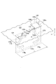
- FIG. 9 a part of the surface of the tread portion 112 of the tire 110 of the second embodiment is schematically shown in a state of being developed on a flat surface.
- FIG. 10 the fragmentary perspective view of the tread surface of the tire 110 of 2nd Embodiment is shown.
- FIG. 11 shows a cross-sectional view taken along line XI-XI in FIG.
- the tire 110 is not limited to the application target, but is typically a pneumatic tire used for a large vehicle such as a vehicle construction machine.
- the tread portion 112 of the tire 110 has an arbitrary pattern (tread pattern).
- the tread pattern shown in FIG. 9 includes a pair of circumferential grooves 116 extending in the tire circumferential direction (up and down direction in FIG. 9) and a plurality of width direction grooves 118 extending in the tire width direction (left and right direction in FIG. 1). .
- the circumferential grooves 116 are located on both sides of the equator plane CL1 of the tire 110, respectively.
- the plurality of width direction grooves 118 are arranged at equal intervals in the tire circumferential direction between each circumferential groove 116 and each tread end TE1.
- Each width direction groove 118 communicates with each circumferential direction groove 116 at one end, and the other end ends at each tread end TE1.
- the tread pattern is further divided between the central land portion 120 extending in the tire circumferential direction defined between the two circumferential grooves 116 and the two widthwise grooves 118 adjacent to each other in the tire circumferential direction.
- the block-shaped land part 121 is provided. The surfaces of the central land portion 120 and the block-shaped land portion 121 substantially define the tread surface of the tire 110, respectively.
- the tread pattern of the tread portion 112 may be a so-called rib pattern, rug pattern, block pattern, or the like.
- channel 118 may extend in the direction which cross
- the tire 110 has an opening on the surface of the central land portion 120 that defines the tread surface provided in the tread portion 112 to release heat generated in the tread portion 112 in accordance with the work or running of the vehicle on which the tire 110 is mounted.
- An air receiving groove 122 is provided.
- the air receiving groove 122 extends in the tread portion 112 in a direction intersecting the tire circumferential direction, and the groove width is smaller than the groove depth.
- the tire 110 opens to the tread surface side, communicates with the air receiving groove 122, and the groove bottoms 124c and 128c are inclined so that the groove depth on the air receiving groove 122 side becomes deep.
- air introduction grooves 124 and 128 for guiding the air on the tread surface side to the air receiving groove 122 are provided on both ends in the longitudinal direction of the air receiving groove 122.
- the tire 110 is disposed on the groove wall surfaces 122b and 122a of the air receiving groove 122, protrudes in the groove width direction of the air receiving groove 122, and is guided to the air receiving groove 122 by the air introducing grooves 124 and 128 as the tire rotates.
- Air guide protrusions (air guide portions) 144 and 146 are provided for guiding the generated air to the groove bottom side of the air receiving groove 122.
- the air guide protrusions 144 and 146 are respectively arranged on both sides in the groove longitudinal direction with respect to the groove longitudinal center position of the air receiving groove in a tread surface view.
- the tire radial outer ends of the air guide protrusions 144 and 146 are located on the outer side in the tire radial direction from the tire radial inner end of the groove bottom of the air introduction groove 122, and the tires of the air guide protrusions 144 and 146 The radially inner end is located on the inner side in the tire radial direction than the half of the groove depth of the air receiving groove 122.
- the air receiving groove 122 has an air receiving groove main body part 122m located on the center side in the groove longitudinal direction from the air guiding protrusions 144 and 146 in the tread surface view, and the air guiding protrusion 144 side in the tread surface view.
- An air receiving groove side portion 122p communicating with the air introducing groove 124 and an air receiving groove side portion 122q communicating with the air introducing groove 128 on the air guiding projection 146 side are configured.
- the air introduction grooves 124 and 128 are respectively arranged on both sides in the groove longitudinal direction with respect to the center position in the groove longitudinal direction of the air receiving groove in the tread surface view, and are arranged in the tire circumferential direction so that their directions are opposite to each other. It extends.
- the air introduction grooves 124 and 128 gradually decrease in depth as they extend in the tire circumferential direction, and the bottom surfaces (groove bottoms) 124c and 128c of the air introduction grooves 124 and 128 are inclined in a flat surface shape. It is on the surface (slope).
- the bottom surface 124c is inclined so that the groove depth on the air receiving groove side portion 122p side is deep
- the bottom surface 128c is inclined so that the groove depth on the air receiving groove side portion 122q side is deep.
- the air guide protrusion 144 is disposed at the boundary between the air receiving groove main body part 122m and the air receiving groove side part 122p, and the air guiding protrusion 146 is the boundary between the air receiving groove main body part 122m and the air receiving groove side part 122q. Is arranged.
- the height of the tire radial outer end 144h of the air guide protrusion 144 is set to be equal to or higher than the height of the tire radial inner end 124cb of the bottom surface 124c.
- the height of the radially outer end 146h is equal to or higher than the height of the tire radial inner end 128cb of the bottom surface 128c.
- the tire radial inner ends 144b and 146b of the air guide protrusions 144 and 146 are located on the inner side in the tire radial direction than the half position (D1 / 2 depth position) of the groove depth D1 of the air receiving groove 122. To do.
- the air introduction groove is used when the tire 110 rotates in one direction for the vehicle to operate or travel.
- 124 and 128 are provided so as to be positioned forward and backward in the one direction, respectively.
- the air introduction groove 124 functions to introduce air (atmosphere) flowing into the air introduction groove 124 into the air receiving groove side portion 122p when the tire 110 rotates in the one direction.
- the air guide projection 144 has an air receiving groove side portion 122p whose side wall 144f (air guide wall) is outward with respect to the central position in the longitudinal direction of the air receiving groove 122 at the position where the air guiding protrusion 144 is formed.
- the air receiving groove main body portion 122m Increases the fluid resistance in the longitudinal direction of the groove from the air receiving groove main body portion 122m to the air receiving groove main body portion 122m, and allows air flowing into the air introducing groove 124 to efficiently reach the groove bottom portion of the air receiving groove main body portion 122m. It functions to suppress the air flowing into the air receiving groove 122 from the groove side portion 122p from returning to the air receiving groove side portion 122p. At this time, the other air introduction groove 128 functions as an air outflow path after flowing in the air receiving groove 122.
- the air guide protrusion 146 has an air receiving groove side part 122q that has a side wall 146f (air guide wall) that faces outward in the groove longitudinal center of the air receiving groove 122 at the position where the air guiding protrusion 146 is formed. It increases the fluid resistance in the longitudinal direction of the groove from the air receiving groove main body 122m to the air receiving groove main body 122m, so that the air flowing into the air introducing groove 128 reaches the groove bottom portion of the air receiving groove main body 122m efficiently.
- the air introduction groove 124 functions as an air outflow path after flowing in the air receiving groove 122.
- the air flowing through the air receiving groove 122 serves to remove heat from the tread portion 112.
- these components such as the air receiving groove 122 are arranged along the tire circumferential direction.
- Each of the plurality of air receiving grooves 122 is open to the surface of the central land portion 120 constituting the tread portion 112 (the tread surface of the tire 110).
- the plurality of air receiving grooves 122 are arranged at equal intervals in the tire circumferential direction and parallel to each other.
- the plurality of air receiving grooves 122 can be arranged at different intervals or non-parallel to each other.
- the air receiving groove 122 extends in a direction intersecting the tire circumferential direction with respect to the tire circumferential direction. That is, it extends non-parallel to the tire circumferential direction.
- the intersection angle ⁇ 1 is set so as to be in the range of 0 ° ⁇ 1 ⁇ 90 °, and preferably in the range of 0 ° ⁇ 1 ⁇ 60 °.
- the air receiving groove 122 shown in the figure has one end and the other end in the longitudinal direction in the central land portion 120.
- the air receiving groove 122 extends in the central land portion 120 and terminates in the central land portion 120.
- the air receiving groove 122 may be communicated with both or one of the circumferential grooves 116 at both or both ends in the longitudinal direction thereof, but considering the decrease in rigidity of the central land portion 120, It is desirable not to communicate as in the illustrated example.
- each air receiving groove 122 has a U-shaped cross section, and groove wall surfaces 122 a and 122 b formed of a pair of flat surfaces facing each other, and both groove wall surfaces 122 a, And a groove bottom 122c formed of a flat surface continuous to 122b.
- the air introduction grooves 124 and 128 are open to the surface (tread surface) of the central land portion 120, respectively. As a result, air can be taken into the air introduction grooves 124 and 128 from the periphery of the tire 110.
- the air introduction groove 124 has groove wall surfaces 124a and 124b made of a pair of flat surfaces facing each other, and a bottom surface 124c made of a flat surface connected to both groove wall surfaces 124a and 124b.
- the air introduction groove 128 has groove wall surfaces 128a and 128b made of a pair of flat surfaces opposed to each other, and a bottom surface 128c made of a flat surface connected to both groove wall surfaces 128a and 128b.
- the bottom surface 124c of the air introduction groove 124 is formed as an inclined surface that inclines inward in the tire radial direction from the surface (tread surface) of the central land portion 120. For this reason, the groove depth gradually becomes deeper toward the air receiving groove 122, and both the groove wall surfaces 124a and 124b have a right triangle shape.
- the bottom surface 124c may extend in a non-inclined state, but by using this as the inclined surface, air flowing into the air receiving groove 122 from the air introduction groove 124 is directed toward the groove bottom of the air receiving groove 122. Can be given greater propulsion power.
- the inclination angle ⁇ 1 (FIG. 10) of the inclined surface of the air introduction groove 124 with respect to the surface (tread surface) of the central land portion 120 of the bottom surface 124c is 45 ° or less, preferably in the range of 20 ° to 30 °. Is desirable. This is because the flow rate of air from the air introduction groove 124 to the air receiving groove 122 increases as the inclination angle ⁇ 1 increases, but when the inclination angle ⁇ 1 exceeds 45 °, the air flow in the vicinity of the air receiving groove 122. Is easily peeled off from the bottom surface 124c, and the air flow rate is reduced.
- the air introduction grooves 124 and 128 and the air guide protrusions 144 and 146 are arranged so as to be point-symmetric on both ends of the air receiving groove 122 in the longitudinal direction in the tread surface view. Therefore, the configuration of the air introduction groove 128 is a configuration that is point-symmetrical (a shape that overlaps when rotated by 180 °) around the symmetrical center M1 (see FIG. 9) on the tire equatorial plane CL1 with respect to the air receiving groove 124. The configuration is the same as that of the air receiving groove 124.
- the air that has flowed into the air receiving groove 122 along the air guide protrusion 144 from the air introduction grooves 124 and 128 passes through the deep portion of the tread portion 112 by the air guide protrusion 144. Air can be efficiently flowed in the vicinity thereof. Therefore, the groove bottom of the air receiving groove 122, that is, the deep portion of the tread portion 112 is cooled by heat transfer accompanying contact with air, thereby releasing heat from the deep portion of the tread portion 112 and accompanying tread portion 112. The temperature of the deep part can be reduced. Therefore, the tire 110 can sufficiently cool the deep portion of the tread portion 112.
- the protrusion height H1 (see FIG. 11) of each of the air guide protrusions 144 and 146 in the groove width direction of the air receiving groove 122 is in the range of 15 to 75% of the groove width W1 of the air receiving groove 122. It is preferable. Thereby, air can be efficiently flowed into the air receiving groove main body portion 122m from the air receiving groove side portion 122p or the air receiving groove side portion 122q, and the groove bottom of the air receiving groove 122, in particular, the groove bottom can be efficiently cooled. Can do.
- the air flowing into the air receiving groove main body portion 122m along the air guiding protrusion 144 from the air receiving groove side portion 122p gets over the air guiding protrusion 144 and the groove bottom of the air receiving groove main body portion 122m. It is difficult to reach the portion, and the air that has flowed into the air receiving groove main body portion 122m along the air guiding protrusion 146 from the air receiving groove side portion 122q passes over the air guiding protrusion 146 and is formed in the groove of the air receiving groove main body portion 122m. It is difficult to reach the bottom portion, and the groove bottom 122c cannot be efficiently cooled.
- the fluid resistance between air flowing into the air receiving groove main body portion 122m along the air guiding protrusion 144 from the air receiving groove side portion 122p and the wall surface of the air guiding protrusion 144 increases.
- the air that has flowed in before reaching the groove bottom portion of the air receiving groove main body portion 122m easily decelerates, and the groove bottom portion of the air receiving groove main body portion 122m cannot be efficiently cooled.
- the outer end of the air guide protrusion 144 is disposed at the boundary between the air receiving groove main body portion 122m and the air receiving groove side portion 122p. By disposing at this position, the air introduced into the air receiving groove side portion 122p can be efficiently moved along the air guide protrusion 144 compared with the case where the air receiving groove side portion 122p is disposed closer to the center position 132m in the groove longitudinal direction. It is easy to guide to the groove bottom 122c.
- the outer end of the air guide protrusion 146 is also preferably arranged at the boundary between the air receiving groove main body portion 122m and the air receiving groove side portion 122q for the same reason.
- the tire radial direction depth E1 (refer FIG. 11) of the air guidance protrusions 144 and 146 is located in a tire radial direction inner side rather than the half position of the groove depth D1 of the air receiving groove 122.
- the air guide protrusions 144 and 146 are illustrated as examples that do not reach the groove bottom 122 c of the air receiving groove 122.
- low protrusion portions G1 in which the protrusion height H1 gradually decreases toward the inner side in the tire radial direction may be arranged.
- each block-shaped land portion 121 may be provided in each block-shaped land portion 121 instead of the central land portion 120.
- the air introduction grooves 124 and 128 extend in the tire circumferential direction so that the air can smoothly flow into the air introduction grooves 124 and 128. It is also possible to adopt a configuration in which the direction in which the introduction grooves 124 and 128 extend is extended in other directions (for example, the direction intersecting the tire circumferential direction and the tire width direction).
- the air receiving groove 122 may have, for example, a V-shaped cross section.
- the pair of groove wall surfaces facing each other is a flat surface
- the groove bottom is a crossing portion of both groove wall surfaces and has a straight line shape.
- FIG. 13 is a partial perspective view of the tread surface of the tire according to the third embodiment.
- the air receiving groove 122 is positioned on the outer side in the longitudinal direction of the groove in the tread surface view.
- Air guide protrusions 154 and 156 that are inclined with respect to the tire radial direction K1 are disposed. Each of the air guide protrusions 154 and 156 is linear when viewed from the groove wall surface side.
- the air that has flowed into the groove on the outer side in the longitudinal direction of the groove in the tread surface view from the air guide protrusions 154 and 156 becomes narrower as compared with the second embodiment toward the groove bottom.
- the flow rate of air toward the groove bottom can be increased. Therefore, it is possible to further improve the heat dissipation performance than the second embodiment (for example, increase the heat dissipation performance by about a little less than 10% compared to the second embodiment).
- FIG. 14 is a partial perspective view of the tread surface of the tire according to the fourth embodiment.
- the air receiving groove 122 is positioned on the outer side in the longitudinal direction of the groove in the tread surface view. Air guide protrusions 164 and 166 that are inclined with respect to the tire radial direction K1 are disposed.
- the air guide protrusions 164 and 166 are curved as viewed from the groove wall surface side as compared with the third embodiment, and thereby, the end portions in the tire radial direction of the air guide protrusions 164 and 166 are formed. It is easy for air to smoothly flow to (the end on the groove bottom side).
- FIG. 15 is a partial perspective view of the tread surface of the tire according to the fifth embodiment.
- air guide protrusions 174 and 176 are arranged instead of the air guide protrusions 164 and 166 as compared with the fourth embodiment.
- the air guide protrusion 174 has a tire radial inner portion 174g that guides air inward in the longitudinal direction of the groove as viewed in the tread surface, at the tire radial inner end (end on the groove bottom side).
- the air guide protrusion 176 also has a tire radial inner portion 176g that guides air inward in the groove longitudinal direction as viewed in the tread surface, at the tire radial inner end (end on the groove bottom side).
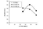
- the projection height H1 is set to 25% of the air receiving groove 122, and the ratio of the guide depth to the air receiving groove depth is changed as a parameter (50%, 75%, 100%) in the same manner.
- the heat transfer coefficient was calculated. The calculation results are also shown in FIG.
- the heat transfer rate is 50% of the vertical depth E1 of the air guiding protrusions 144 and 146 with respect to the groove depth D1 of the air receiving groove 122.
- the ratio of the vertical depth E1 of the air guide protrusions 144 and 146 to the groove depth D1 of the air receiving groove 122 gradually decreases as the ratio increases.
- the inventor sets the protrusion height H1 to 50% of the air receiving groove 122 in the tire of the third embodiment, and the vertical depths of the air guide protrusions 154 and 156 with respect to the groove depth D1 of the air receiving groove.
- the ratio of E1 was set to 75%, and the heat transfer coefficient of the entire groove bottom was calculated by analytical calculation.
- the calculation results are shown in FIG. In FIG. 17, for comparison, in analysis calculation example 1, with respect to the tire 110 of the second embodiment, the protrusion height H1 is set to 50% of the air receiving groove 122 and the groove depth of the air receiving groove 122 is set.
- the analysis calculation result of the heat transfer coefficient when the ratio of the vertical direction depth E1 of the air guide protrusions 154 and 156 to D1 is set to 75% is also illustrated.
- the third embodiment is more than the second embodiment.
- the result was a high heat transfer rate.
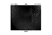
- FIG. 18 shows a schematic diagram obtained by this analysis calculation regarding the air flow on the groove wall surface.
- the tire (FIG. 18, an example of the second embodiment) in which the air guiding protrusions 144 and 146 are arranged is more grooved than the tire (FIG. 19, an example of the conventional example) that is not arranged.
- the result was good air flow at the bottom.
- the air guide protrusion is positioned with respect to the tire radial direction K1 so as to be positioned on the outer side in the groove longitudinal direction of the air receiving groove 122 in the tread surface view as the groove depth increases.
- Each is inclined.
- the groove width in the longitudinal direction X of the air receiving groove 22 of the air guide grooves 26, 30 may be narrowed as the groove depth increases. .
Landscapes
- Engineering & Computer Science (AREA)
- Mechanical Engineering (AREA)
- Tires In General (AREA)
Abstract
Cette invention concerne un pneumatique, comprenant; au moins une rainure d'admission d'air (22, 122) qui est ménagée dans une section de bande de roulement de pneu (12, 112), qui s'étend dans une direction intéressant le sens de la circonférence du pneumatique, et qui présente une largeur de rainure (W, W1) qui est inférieure à la profondeur de rainure (D, D1); une rainure d'introduction d'air (24, 124) qui donne sur le côté de surface de bande de roulement, qui communique avec la rainure d'admission d'air (22, 122), et qui introduit de l'air (AR) sur le côté de surface de bande de roulement dans la rainure d'admission d'air (22, 122) conjointement avec la rotation du pneu; et des sections de guidage d'air (26, 30, 144, 146, 154, 156, 164, 166, 174, 176) qui croisent la rainure d'admission d'air (22, 122), qui comprennent des surfaces de guidage d'air (26b, 30b, 144f, 146f) orientées vers l'extérieur par rapport à une position centrale dans le sens de la longueur de rainure de la rainure d'admission d'air (22, 122) à la position d'intersection avec la rainure d'admission d'air (22, 122), et qui guident l'air (AR) introduit dans la rainure d'admission d'air (22, 122) par la rainure d'introduction d'air (24, 124) vers le côté du fond de rainure (22c, 122c) de la rainure d'admission d'air (22, 122) au moyen des surfaces de guidage d'air (26b, 30b, 144f, 146f).
Priority Applications (4)
| Application Number | Priority Date | Filing Date | Title |
|---|---|---|---|
| ES16765007T ES2770337T3 (es) | 2015-03-19 | 2016-03-16 | Neumático |
| CN201680016602.3A CN107428203B (zh) | 2015-03-19 | 2016-03-16 | 轮胎 |
| US15/558,426 US20180056730A1 (en) | 2015-03-19 | 2016-03-16 | Tire |
| EP16765007.6A EP3272552B1 (fr) | 2015-03-19 | 2016-03-16 | Pneumatique |
Applications Claiming Priority (4)
| Application Number | Priority Date | Filing Date | Title |
|---|---|---|---|
| JP2015055752A JP6578114B2 (ja) | 2015-03-19 | 2015-03-19 | タイヤ |
| JP2015-055752 | 2015-03-19 | ||
| JP2015-138538 | 2015-07-10 | ||
| JP2015138538 | 2015-07-10 |
Publications (1)
| Publication Number | Publication Date |
|---|---|
| WO2016148178A1 true WO2016148178A1 (fr) | 2016-09-22 |
Family
ID=56919887
Family Applications (1)
| Application Number | Title | Priority Date | Filing Date |
|---|---|---|---|
| PCT/JP2016/058285 Ceased WO2016148178A1 (fr) | 2015-03-19 | 2016-03-16 | Pneumatique |
Country Status (5)
| Country | Link |
|---|---|
| US (1) | US20180056730A1 (fr) |
| EP (1) | EP3272552B1 (fr) |
| CN (1) | CN107428203B (fr) |
| ES (1) | ES2770337T3 (fr) |
| WO (1) | WO2016148178A1 (fr) |
Families Citing this family (2)
| Publication number | Priority date | Publication date | Assignee | Title |
|---|---|---|---|---|
| JP6890086B2 (ja) | 2017-12-12 | 2021-06-18 | 株式会社ブリヂストン | 重荷重用タイヤ |
| JP7215900B2 (ja) * | 2018-12-27 | 2023-01-31 | Toyo Tire株式会社 | 空気入りタイヤ |
Citations (7)
| Publication number | Priority date | Publication date | Assignee | Title |
|---|---|---|---|---|
| JP2007191093A (ja) * | 2006-01-20 | 2007-08-02 | Bridgestone Corp | 建設車両用タイヤ |
| JP2007230399A (ja) * | 2006-03-01 | 2007-09-13 | Bridgestone Corp | 空気入りタイヤ |
| WO2008029563A1 (fr) * | 2006-09-05 | 2008-03-13 | Bridgestone Corporation | Pneu pour véhicule de construction |
| JP2009179219A (ja) * | 2008-01-31 | 2009-08-13 | Bridgestone Corp | 空気入りタイヤ |
| JP2012179948A (ja) * | 2011-02-28 | 2012-09-20 | Bridgestone Corp | 建設車両用ラジアルタイヤ |
| JP2014084109A (ja) * | 2012-10-26 | 2014-05-12 | The Goodyear Tire & Rubber Co | オフロード用のタイヤ |
| WO2014142346A1 (fr) * | 2013-03-13 | 2014-09-18 | 株式会社ブリヂストン | Pneumatique |
Family Cites Families (7)
| Publication number | Priority date | Publication date | Assignee | Title |
|---|---|---|---|---|
| JPH02241806A (ja) * | 1989-03-15 | 1990-09-26 | Bridgestone Corp | ギャップ差をもつサイプを有する空気入りタイヤとタイヤモールドのサイプ形成用ブレード |
| DE19651792A1 (de) * | 1996-12-12 | 1998-06-18 | Continental Ag | Fahrzeugreifen mit einer Lauffläche mit Einschnitten |
| DE502004011794D1 (de) * | 2004-03-26 | 2010-12-02 | Continental Reifen Deutschland | Fahrzeugluftreifen |
| JP5099914B2 (ja) * | 2008-10-03 | 2012-12-19 | 東洋ゴム工業株式会社 | 空気入りタイヤ |
| DE102009044246A1 (de) * | 2009-10-14 | 2011-05-12 | Continental Reifen Deutschland Gmbh | Laufstreifenprofil eines Fahrzeugluftreifens |
| JP5429267B2 (ja) * | 2011-11-28 | 2014-02-26 | 横浜ゴム株式会社 | 空気入りタイヤ |
| JP5977696B2 (ja) * | 2013-03-13 | 2016-08-24 | 株式会社ブリヂストン | 空気入りタイヤ |
-
2016
- 2016-03-16 US US15/558,426 patent/US20180056730A1/en not_active Abandoned
- 2016-03-16 EP EP16765007.6A patent/EP3272552B1/fr active Active
- 2016-03-16 CN CN201680016602.3A patent/CN107428203B/zh active Active
- 2016-03-16 ES ES16765007T patent/ES2770337T3/es active Active
- 2016-03-16 WO PCT/JP2016/058285 patent/WO2016148178A1/fr not_active Ceased
Patent Citations (7)
| Publication number | Priority date | Publication date | Assignee | Title |
|---|---|---|---|---|
| JP2007191093A (ja) * | 2006-01-20 | 2007-08-02 | Bridgestone Corp | 建設車両用タイヤ |
| JP2007230399A (ja) * | 2006-03-01 | 2007-09-13 | Bridgestone Corp | 空気入りタイヤ |
| WO2008029563A1 (fr) * | 2006-09-05 | 2008-03-13 | Bridgestone Corporation | Pneu pour véhicule de construction |
| JP2009179219A (ja) * | 2008-01-31 | 2009-08-13 | Bridgestone Corp | 空気入りタイヤ |
| JP2012179948A (ja) * | 2011-02-28 | 2012-09-20 | Bridgestone Corp | 建設車両用ラジアルタイヤ |
| JP2014084109A (ja) * | 2012-10-26 | 2014-05-12 | The Goodyear Tire & Rubber Co | オフロード用のタイヤ |
| WO2014142346A1 (fr) * | 2013-03-13 | 2014-09-18 | 株式会社ブリヂストン | Pneumatique |
Also Published As
| Publication number | Publication date |
|---|---|
| ES2770337T3 (es) | 2020-07-01 |
| EP3272552B1 (fr) | 2019-11-13 |
| US20180056730A1 (en) | 2018-03-01 |
| CN107428203A (zh) | 2017-12-01 |
| EP3272552A1 (fr) | 2018-01-24 |
| EP3272552A4 (fr) | 2018-03-21 |
| CN107428203B (zh) | 2019-08-27 |
Similar Documents
| Publication | Publication Date | Title |
|---|---|---|
| JP6149032B2 (ja) | 内部空間を持つ溝を有するタイヤトレッド | |
| JP6514869B2 (ja) | 空気入りタイヤ | |
| JP5805123B2 (ja) | 空気入りタイヤ | |
| JP2014522772A5 (fr) | ||
| CN105473347B (zh) | 充气轮胎 | |
| JP2014205410A (ja) | 空気入りタイヤ | |
| WO2016148178A1 (fr) | Pneumatique | |
| CN112334331B (zh) | 重载用轮胎 | |
| JP6578114B2 (ja) | タイヤ | |
| JP5557821B2 (ja) | 空気入りタイヤ | |
| WO2013191119A1 (fr) | Pneumatique | |
| JP5697868B2 (ja) | 運搬車両用タイヤ | |
| JP4583846B2 (ja) | 空気入りタイヤ | |
| JP4420598B2 (ja) | 空気入りタイヤ | |
| JP6735131B2 (ja) | タイヤ | |
| US12005743B2 (en) | Tire | |
| JP2013006574A (ja) | 空気入りタイヤ | |
| JP5944756B2 (ja) | タイヤ | |
| JP5557943B1 (ja) | 空気入りタイヤ | |
| JP6161947B2 (ja) | タイヤ | |
| JP7077341B2 (ja) | 重荷重用タイヤ | |
| JP6534300B2 (ja) | タイヤ | |
| JP2014213830A (ja) | タイヤ | |
| CN121464048A (zh) | 重型轮胎 | |
| JP2019104362A (ja) | 重荷重用タイヤ |
Legal Events
| Date | Code | Title | Description |
|---|---|---|---|
| 121 | Ep: the epo has been informed by wipo that ep was designated in this application |
Ref document number: 16765007 Country of ref document: EP Kind code of ref document: A1 |
|
| WWE | Wipo information: entry into national phase |
Ref document number: 15558426 Country of ref document: US |
|
| NENP | Non-entry into the national phase |
Ref country code: DE |
|
| REEP | Request for entry into the european phase |
Ref document number: 2016765007 Country of ref document: EP |