EP3273701A1 - Audiosignalprozessor - Google Patents
Audiosignalprozessor Download PDFInfo
- Publication number
- EP3273701A1 EP3273701A1 EP16180173.3A EP16180173A EP3273701A1 EP 3273701 A1 EP3273701 A1 EP 3273701A1 EP 16180173 A EP16180173 A EP 16180173A EP 3273701 A1 EP3273701 A1 EP 3273701A1
- Authority
- EP
- European Patent Office
- Prior art keywords
- bit
- audio signal
- audio
- clock
- digital
- Prior art date
- Legal status (The legal status is an assumption and is not a legal conclusion. Google has not performed a legal analysis and makes no representation as to the accuracy of the status listed.)
- Granted
Links
Images



Classifications
-
- G—PHYSICS
- G06—COMPUTING OR CALCULATING; COUNTING
- G06F—ELECTRIC DIGITAL DATA PROCESSING
- G06F3/00—Input arrangements for transferring data to be processed into a form capable of being handled by the computer; Output arrangements for transferring data from processing unit to output unit, e.g. interface arrangements
- G06F3/16—Sound input; Sound output
- G06F3/165—Management of the audio stream, e.g. setting of volume, audio stream path
-
- H—ELECTRICITY
- H04—ELECTRIC COMMUNICATION TECHNIQUE
- H04R—LOUDSPEAKERS, MICROPHONES, GRAMOPHONE PICK-UPS OR LIKE ACOUSTIC ELECTROMECHANICAL TRANSDUCERS; ELECTRIC HEARING AIDS; PUBLIC ADDRESS SYSTEMS
- H04R1/00—Details of transducers, loudspeakers or microphones
- H04R1/20—Arrangements for obtaining desired frequency or directional characteristics
- H04R1/32—Arrangements for obtaining desired frequency or directional characteristics for obtaining desired directional characteristic only
- H04R1/40—Arrangements for obtaining desired frequency or directional characteristics for obtaining desired directional characteristic only by combining a number of identical transducers
- H04R1/406—Arrangements for obtaining desired frequency or directional characteristics for obtaining desired directional characteristic only by combining a number of identical transducers microphones
-
- H—ELECTRICITY
- H04—ELECTRIC COMMUNICATION TECHNIQUE
- H04R—LOUDSPEAKERS, MICROPHONES, GRAMOPHONE PICK-UPS OR LIKE ACOUSTIC ELECTROMECHANICAL TRANSDUCERS; ELECTRIC HEARING AIDS; PUBLIC ADDRESS SYSTEMS
- H04R3/00—Circuits for transducers
- H04R3/005—Circuits for transducers for combining the signals of two or more microphones
-
- H—ELECTRICITY
- H04—ELECTRIC COMMUNICATION TECHNIQUE
- H04R—LOUDSPEAKERS, MICROPHONES, GRAMOPHONE PICK-UPS OR LIKE ACOUSTIC ELECTROMECHANICAL TRANSDUCERS; ELECTRIC HEARING AIDS; PUBLIC ADDRESS SYSTEMS
- H04R2430/00—Signal processing covered by H04R, not provided for in its groups
- H04R2430/20—Processing of the output signals of the acoustic transducers of an array for obtaining a desired directivity characteristic
-
- H—ELECTRICITY
- H04—ELECTRIC COMMUNICATION TECHNIQUE
- H04R—LOUDSPEAKERS, MICROPHONES, GRAMOPHONE PICK-UPS OR LIKE ACOUSTIC ELECTROMECHANICAL TRANSDUCERS; ELECTRIC HEARING AIDS; PUBLIC ADDRESS SYSTEMS
- H04R2499/00—Aspects covered by H04R or H04S not otherwise provided for in their subgroups
- H04R2499/10—General applications
- H04R2499/13—Acoustic transducers and sound field adaptation in vehicles
Definitions
- the present invention relates to audio signal processing and more particular to systems and methods for generating an analog audio signal from digital microphone signals and in particular to an audio signal processor for the creation of an analog microphone signal with directional characteristic from 1-bit signals of at least two digitally ported microphones.
- Digital 1-bit audio signals are known but audio signal processing based on 1-bit signals is limited so far to rather simple signal manipulation like volume control as described in US 20030151535 A1 , or require a transformation into n-bit signals (n>1) for applying digital signal processing, and wherein the 1-bit signal itself is only used for signal transport as described in US6295014 B1 .
- Digital microphones with 1-bit pulse-density-modulated PDM output are known. Usually these microphones are constructed in MEMS Micro Electro Mechanical System technology and have omni-spatial characteristic, i.e. no preferred direction of sound reception.
- the signals of such digital microphones supplying a digital audio system are often also required in analog audio systems, where furthermore a directional microphone characteristic is required, e.g. in order to improve the signal-to-noise ratio of a desired sound source, e.g. a human speaker in a running car conducting hands-free communication.
- an audio signal processor being capable of generating an analog audio signal with directional characteristic from at least two 1-bit audio signals of digital microphones which does not require sophisticated mathematical operation, time-frequency domain transformations and thus a complex digital signal processor (DSP) for such kind of complex operation.
- DSP complex digital signal processor
- An apparatus and method are disclosed that generate an analog audio signal with directional characteristic from at least two 1-bit audio signals generated by respective digital microphones, wherein the apparatus comprises a shift register of length n for bit-clocked throughput of at least one 1-bit audio signal and a combiner for combining at least two 1-bit audio signals to an interlaced 1-bit audio signal with doubled bit frequency.
- the apparatus can be an audio signal processor that generates the analog audio signal with directional characteristic from the two or more 1-bit audio signals provided by the digital microphones.
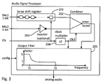
- Linear shift and add beamforming of the 1-bit digital audio signals is carried out by means of a serial shift register and a combiner, the latter producing a 1-bit audio signal with doubled bit frequency as interlaced signal of a first digital microphone signal being put through said serial shift register and an optionally inverted second 1-bit microphone signal.
- the audio signal processor all required processing steps are carried out with Boolean logical elements and filters, whereas in a preferred embodiment also the filters consist of digital gates, so that all active elements of the audio processor can be implemented by digital logic, and implementation of the audio signal processor in a device is very inexpensive, requires less and only simple digital circuitry and thus is less power consuming compared to complex DSP circuits by using standard digital logical circuits.
- the audio signal processor 104 as part of an audio system 100 generates an analog audio signal with directional characteristic.
- the signal of the first digital microphone 101 is delayed by d/c milliseconds, where c is the speed of sound 340 m/s at room temperature, and subtracted from the second, un-delayed microphone 102 signal.
- Said shift register 201 delays the 1-bit audio signal of said first digital microphone 101.
- Said interlaced signal is composed of alternating bits of the delayed first and the second microphone signal creating the so-called 1-bit audio output signal which forms a first analog audio signal.
- the second microphone signal can also be inverted before combined with the delayed first microphone signal influencing the directional characteristic of the analog audio signal.
- the interlaced 1-bit audio output signal produced by the combiner will then be filtered by the output filter to produce a filtered analog audio signal with respective directional characteristic.
- the output filter is a suitable low-pass filter filtering out respective undesired out-of-band components, which do not contribute to the audible frequency range of the interlaced 1-bit audio output signal in the interlaced 1-bit audio output signal. If the second microphone signal is inverted before combined with the delayed first microphone signal the (filtered) analog audio signal has a respective cardioid spatial characteristic.
- the band edge of said low pass filter should be chosen not higher than 48 kHz, in the given preferred example preferably not higher than 24 kHz in order to avoid spatial aliasing, but can also be set to an even lower frequency depending on the requirements of the analog audio system.
- said inverter 203 can also invert the delayed signal of the first microphone 101 instead of the un-delayed second microphone 102.
- Different directional characteristics e.g. hyper-cardioid of super-cardioid can be achieved with different, suitable shift register 201 length n.
- the exact value of n depends on the desired angular direction of maximum attenuation and the audio sample rate and the microphone distance, as well as the speed of sound which is usually treated as a constant although it varies with atmospheric conditions.
- the inverter 203 can also be omitted, then the resulting directional characteristic is not cardioid or similar, see above, instead constructive interference is exploited, resulting in a signal enhancement of up to 6 dB in a preferred direction, for an array of two microphones.
- the embodiment without inverter is suitable for cascading more than two microphones with additional shift registers forming a phased array. Interlacing more than two shifted microphone signals will increase the bit clock of the interlaced signal by a factor equal to the number of microphones in the phased array
- a low pass filter 205 is not necessarily required as part of the audio signal processor. It is however preferable to integrate said filter into the audio signal processor 104, which is referred to as output filter 205 in the following.
- the output filter can be designed as FIR Finite Impulse Response filter with standard filter design skills, and an exemplary transfer function of such output filter is sketched in the box 205 for the output filter in Fig. 2 .
- output filter 205 all active components of said output filter 205 are digital i.e. Boolean, so production of the complete audio signal processor is cheap and simple.
- Such output filter 205 consists of two serial-in parallel-out shift registers 301, 303 of length m referred to as "parallel shift registers" or "second and third shift register” in the following as shown in Fig. 3 .
- the interlaced signal is dynamically put through the second shift register 301 with bit clock 2f.
- Third shift register 303 holds a bit pattern, which is the 1-bit representation of a desired FIR filter as outlined above, whereas the oversampling factor of this 1-bit representation is twice of the oversampling factor of the 1-bit signals of the digital microphones 128 in the given example.
- Third shift register 303 can be hard-coded with said static bit pattern; however, in a preferred embodiment there is a configuration interface comprising a config-clock signal and a config-data signal. By this means, said static bit pattern can be loaded into said third shift register 303.
- Each of the m stages of both parallel shift registers 301, 303 are input to a logical Exclusive-Or XOR Gate 302, and the outputs of all m XOR Gates are connected via m resistors 304 with a resistor value of e.g. 1 M Ohm.
- the resistors 304 carry out the average over the output states of the m XOR-gates 302, producing an analog audio signal as output of the audio signal processor 104.
- the audio system 100 further comprises an analog audio system 105 which is a typical sink of the analog output signal of the audio signal processor 104, and in an embodiment where the analog audio system is the only audio sink in the application, both clock signal clk and supply voltage Vdd for the audio signal processor 104 as well as the digital microphones 101, 102 are provided by the analog audio system 105.
- an analog audio system 105 which is a typical sink of the analog output signal of the audio signal processor 104
- both clock signal clk and supply voltage Vdd for the audio signal processor 104 as well as the digital microphones 101, 102 are provided by the analog audio system 105.
- a typical deployment of the audio signal processor is an application, where a digital audio system 103 is directly processing the digital signals of the digital microphones 101, 102.
- the digital audio system 103 provides the clock signal and also power supply for the digital microphones 101, 102, and in such an embodiment the audio signal processor 104 gets its clock signal clk from the digital audio system 103, and not from the analog audio system 105 where the analog output signal goes to.
- the audio signal processor 104 must maintain operation even in case the digital audio system ceased operation, e.g. due to an accident.
- operation of the audio signal processor 104 and also of the digital microphones 101, 102 is secured by an alternative supply of both power and clock from the digital audio system 103 and from the analog audio system 105 as backup.
- Alternative power supply can be simply realized by means of a pair of diodes 106 as shown in Fig. 1 , although more complex switches are also possible.
- Alternative clock supply of the audio signal processor 104 and the digital microphones 104 is realized by means of a clock selector 107, that outputs the clock signal clk_dig provided by the digital audio system 103 in case it is a valid clock signal, and elk_analog that is provided by the analog audio system 105 otherwise.
- the output of the clock selector is the clock signal of both audio signal processor 104 and digital microphones 101, 102.
- Fig. 4 shows an exemplary embodiment of a method 400 for generating the analog audio signal with directional characteristic from at least two 1-bit audio signals of digital microphones as described above.
- the method comprises a bit-clocked putting through 410 of a first 1-bit audio signal of the first digital microphone 101 in the shift register of length n 201 and producing 420 a shift register output signal with single bit frequency.
- the shift register output signal is combined with the second 1-bit audio signal of the second digital microphone 102 by the combiner 202 to generate 440 an interlaced 1-bit audio output signal with doubled bit frequency.
- the interlaced 1-bit audio output signal is filtered in output filter 205 to generate 460 the analog audio signal.
- Embodiments of the subject matter and the operations described in this specification can be implemented in digital electronic circuitry, or in computer software, firmware, or hardware, including the structures disclosed in this specification and their structural equivalents, or in combinations of one or more of them.
- Embodiments of the subject matter described in this specification can be implemented as one or more computer programs, i.e., one or more modules of computer program instructions, encoded on computer storage medium for execution by, or to control the operation of, data processing apparatus.
- the operations described in this specification can be implemented as operations performed by a data processing apparatus on data stored on one or more computer-readable storage devices or received from other sources.
Landscapes
- Engineering & Computer Science (AREA)
- Health & Medical Sciences (AREA)
- Otolaryngology (AREA)
- Physics & Mathematics (AREA)
- Acoustics & Sound (AREA)
- Signal Processing (AREA)
- General Health & Medical Sciences (AREA)
- Theoretical Computer Science (AREA)
- Multimedia (AREA)
- Audiology, Speech & Language Pathology (AREA)
- Human Computer Interaction (AREA)
- General Engineering & Computer Science (AREA)
- General Physics & Mathematics (AREA)
- Circuit For Audible Band Transducer (AREA)
Priority Applications (2)
| Application Number | Priority Date | Filing Date | Title |
|---|---|---|---|
| EP16180173.3A EP3273701B1 (de) | 2016-07-19 | 2016-07-19 | Audiosignalprozessor |
| US15/649,450 US10083001B2 (en) | 2016-07-19 | 2017-07-13 | Audio signal processor |
Applications Claiming Priority (1)
| Application Number | Priority Date | Filing Date | Title |
|---|---|---|---|
| EP16180173.3A EP3273701B1 (de) | 2016-07-19 | 2016-07-19 | Audiosignalprozessor |
Publications (2)
| Publication Number | Publication Date |
|---|---|
| EP3273701A1 true EP3273701A1 (de) | 2018-01-24 |
| EP3273701B1 EP3273701B1 (de) | 2018-07-04 |
Family
ID=56883500
Family Applications (1)
| Application Number | Title | Priority Date | Filing Date |
|---|---|---|---|
| EP16180173.3A Active EP3273701B1 (de) | 2016-07-19 | 2016-07-19 | Audiosignalprozessor |
Country Status (2)
| Country | Link |
|---|---|
| US (1) | US10083001B2 (de) |
| EP (1) | EP3273701B1 (de) |
Citations (10)
| Publication number | Priority date | Publication date | Assignee | Title |
|---|---|---|---|---|
| GB2276495A (en) * | 1991-12-19 | 1994-09-28 | Secr Defence | A digital beamforming array |
| US6295014B1 (en) | 1997-10-24 | 2001-09-25 | Sony United Kingdom Limited | System for processing one-bit audio signals |
| US20030151535A1 (en) | 2001-07-13 | 2003-08-14 | Melanson John Laurence | Circuits, systems and methods for volume control in 1-bit digital audio systems |
| EP1744174A1 (de) * | 2005-07-12 | 2007-01-17 | Mitel Networks Corporation | Überabtastender Strahlformer |
| US20080019548A1 (en) | 2006-01-30 | 2008-01-24 | Audience, Inc. | System and method for utilizing omni-directional microphones for speech enhancement |
| US20080260175A1 (en) | 2002-02-05 | 2008-10-23 | Mh Acoustics, Llc | Dual-Microphone Spatial Noise Suppression |
| US20120213389A1 (en) * | 2011-02-22 | 2012-08-23 | Ricoh Company, Ltd. | Audio mixing device, method thereof, and electronic device |
| US20130117016A1 (en) | 2011-11-07 | 2013-05-09 | Dietmar Ruwisch | Method and an apparatus for generating a noise reduced audio signal |
| US20140132304A1 (en) * | 2012-11-15 | 2014-05-15 | Moshe Haiut | Device and method for direct mixing of pulse density modulation (pdm) signals |
| US20140193000A1 (en) | 2013-01-07 | 2014-07-10 | Dietmar Ruwisch | Method and apparatus for generating a noise reduced audio signal using a microphone array |
Family Cites Families (2)
| Publication number | Priority date | Publication date | Assignee | Title |
|---|---|---|---|---|
| GB2202942B (en) * | 1987-03-21 | 1991-08-21 | Ferranti Plc | Production of directionally limited acoustic power spectra |
| JP2003059182A (ja) * | 2001-08-10 | 2003-02-28 | Teac Corp | 1ビット形式ディジタル信号の記録方法及び記録装置及び付加装置 |
-
2016
- 2016-07-19 EP EP16180173.3A patent/EP3273701B1/de active Active
-
2017
- 2017-07-13 US US15/649,450 patent/US10083001B2/en active Active
Patent Citations (10)
| Publication number | Priority date | Publication date | Assignee | Title |
|---|---|---|---|---|
| GB2276495A (en) * | 1991-12-19 | 1994-09-28 | Secr Defence | A digital beamforming array |
| US6295014B1 (en) | 1997-10-24 | 2001-09-25 | Sony United Kingdom Limited | System for processing one-bit audio signals |
| US20030151535A1 (en) | 2001-07-13 | 2003-08-14 | Melanson John Laurence | Circuits, systems and methods for volume control in 1-bit digital audio systems |
| US20080260175A1 (en) | 2002-02-05 | 2008-10-23 | Mh Acoustics, Llc | Dual-Microphone Spatial Noise Suppression |
| EP1744174A1 (de) * | 2005-07-12 | 2007-01-17 | Mitel Networks Corporation | Überabtastender Strahlformer |
| US20080019548A1 (en) | 2006-01-30 | 2008-01-24 | Audience, Inc. | System and method for utilizing omni-directional microphones for speech enhancement |
| US20120213389A1 (en) * | 2011-02-22 | 2012-08-23 | Ricoh Company, Ltd. | Audio mixing device, method thereof, and electronic device |
| US20130117016A1 (en) | 2011-11-07 | 2013-05-09 | Dietmar Ruwisch | Method and an apparatus for generating a noise reduced audio signal |
| US20140132304A1 (en) * | 2012-11-15 | 2014-05-15 | Moshe Haiut | Device and method for direct mixing of pulse density modulation (pdm) signals |
| US20140193000A1 (en) | 2013-01-07 | 2014-07-10 | Dietmar Ruwisch | Method and apparatus for generating a noise reduced audio signal using a microphone array |
Also Published As
| Publication number | Publication date |
|---|---|
| US20180024809A1 (en) | 2018-01-25 |
| EP3273701B1 (de) | 2018-07-04 |
| US10083001B2 (en) | 2018-09-25 |
Similar Documents
| Publication | Publication Date | Title |
|---|---|---|
| EP3201911B1 (de) | Akustischer prozessor mit niedriger latenzzeit | |
| EP1198974B1 (de) | Hörgerät mit adaptiver anpassung von mikrofonen | |
| CN107743711B (zh) | 匣偏移型麦克风 | |
| US4472834A (en) | Loudspeaker system | |
| US10013965B2 (en) | Calibration system for active noise cancellation and speaker apparatus | |
| US20160365083A1 (en) | Low-Power-Consumption Active Noise-Reduction In-Ear Music Headphones and Method for Noise Reduction | |
| JP6609698B2 (ja) | 歪みを制限するためのシステムおよび方法 | |
| US10972123B1 (en) | Signal processing structure | |
| JP2016015722A5 (de) | ||
| US8014745B1 (en) | High isolation multiple carrier system architecture for communications | |
| KR20190135045A (ko) | 헤드셋들을 위한 유연한 음성 캡처 프론트-엔드 | |
| JP2018531557A6 (ja) | 歪みを制限するためのシステムおよび方法 | |
| US10714071B2 (en) | Active noise reduction device | |
| US10997960B2 (en) | Acoustic processor having low latency | |
| US10083001B2 (en) | Audio signal processor | |
| US7205918B2 (en) | Hearing aid device with an output amplifier having a sigma-delta modulator | |
| US12301769B2 (en) | Echo cancellation | |
| JP2015106799A (ja) | 方法および電子機器 | |
| US11257476B2 (en) | Signal processing apparatus and signal processing method | |
| US20250233944A1 (en) | Echo cancellation | |
| US11477569B2 (en) | Apparatus and method for obtaining directional audio signals | |
| US12632212B2 (en) | User interface for selective filtering of speech and noise | |
| US20180108341A1 (en) | Controlling an audio system | |
| US20230214173A1 (en) | User interface for selective filtering of speech and noise | |
| JP6474246B2 (ja) | オーディオ信号処理回路、車載用オーディオ装置、オーディオコンポーネント装置、電子機器 |
Legal Events
| Date | Code | Title | Description |
|---|---|---|---|
| PUAI | Public reference made under article 153(3) epc to a published international application that has entered the european phase |
Free format text: ORIGINAL CODE: 0009012 |
|
| 17P | Request for examination filed |
Effective date: 20170705 |
|
| AK | Designated contracting states |
Kind code of ref document: A1 Designated state(s): AL AT BE BG CH CY CZ DE DK EE ES FI FR GB GR HR HU IE IS IT LI LT LU LV MC MK MT NL NO PL PT RO RS SE SI SK SM TR |
|
| AX | Request for extension of the european patent |
Extension state: BA ME |
|
| GRAP | Despatch of communication of intention to grant a patent |
Free format text: ORIGINAL CODE: EPIDOSNIGR1 |
|
| RIC1 | Information provided on ipc code assigned before grant |
Ipc: H04R 3/00 20060101AFI20180130BHEP Ipc: H04R 1/40 20060101ALN20180130BHEP |
|
| INTG | Intention to grant announced |
Effective date: 20180215 |
|
| GRAS | Grant fee paid |
Free format text: ORIGINAL CODE: EPIDOSNIGR3 |
|
| GRAA | (expected) grant |
Free format text: ORIGINAL CODE: 0009210 |
|
| AK | Designated contracting states |
Kind code of ref document: B1 Designated state(s): AL AT BE BG CH CY CZ DE DK EE ES FI FR GB GR HR HU IE IS IT LI LT LU LV MC MK MT NL NO PL PT RO RS SE SI SK SM TR |
|
| REG | Reference to a national code |
Ref country code: GB Ref legal event code: FG4D |
|
| REG | Reference to a national code |
Ref country code: CH Ref legal event code: EP |
|
| REG | Reference to a national code |
Ref country code: AT Ref legal event code: REF Ref document number: 1015793 Country of ref document: AT Kind code of ref document: T Effective date: 20180715 |
|
| REG | Reference to a national code |
Ref country code: IE Ref legal event code: FG4D |
|
| REG | Reference to a national code |
Ref country code: DE Ref legal event code: R096 Ref document number: 602016003936 Country of ref document: DE |
|
| REG | Reference to a national code |
Ref country code: FR Ref legal event code: PLFP Year of fee payment: 3 |
|
| REG | Reference to a national code |
Ref country code: NL Ref legal event code: MP Effective date: 20180704 |
|
| REG | Reference to a national code |
Ref country code: LT Ref legal event code: MG4D |
|
| REG | Reference to a national code |
Ref country code: AT Ref legal event code: MK05 Ref document number: 1015793 Country of ref document: AT Kind code of ref document: T Effective date: 20180704 |
|
| PG25 | Lapsed in a contracting state [announced via postgrant information from national office to epo] |
Ref country code: NL Free format text: LAPSE BECAUSE OF FAILURE TO SUBMIT A TRANSLATION OF THE DESCRIPTION OR TO PAY THE FEE WITHIN THE PRESCRIBED TIME-LIMIT Effective date: 20180704 |
|
| PG25 | Lapsed in a contracting state [announced via postgrant information from national office to epo] |
Ref country code: PL Free format text: LAPSE BECAUSE OF FAILURE TO SUBMIT A TRANSLATION OF THE DESCRIPTION OR TO PAY THE FEE WITHIN THE PRESCRIBED TIME-LIMIT Effective date: 20180704 Ref country code: SE Free format text: LAPSE BECAUSE OF FAILURE TO SUBMIT A TRANSLATION OF THE DESCRIPTION OR TO PAY THE FEE WITHIN THE PRESCRIBED TIME-LIMIT Effective date: 20180704 Ref country code: AT Free format text: LAPSE BECAUSE OF FAILURE TO SUBMIT A TRANSLATION OF THE DESCRIPTION OR TO PAY THE FEE WITHIN THE PRESCRIBED TIME-LIMIT Effective date: 20180704 Ref country code: IS Free format text: LAPSE BECAUSE OF FAILURE TO SUBMIT A TRANSLATION OF THE DESCRIPTION OR TO PAY THE FEE WITHIN THE PRESCRIBED TIME-LIMIT Effective date: 20181104 Ref country code: NO Free format text: LAPSE BECAUSE OF FAILURE TO SUBMIT A TRANSLATION OF THE DESCRIPTION OR TO PAY THE FEE WITHIN THE PRESCRIBED TIME-LIMIT Effective date: 20181004 Ref country code: GR Free format text: LAPSE BECAUSE OF FAILURE TO SUBMIT A TRANSLATION OF THE DESCRIPTION OR TO PAY THE FEE WITHIN THE PRESCRIBED TIME-LIMIT Effective date: 20181005 Ref country code: FI Free format text: LAPSE BECAUSE OF FAILURE TO SUBMIT A TRANSLATION OF THE DESCRIPTION OR TO PAY THE FEE WITHIN THE PRESCRIBED TIME-LIMIT Effective date: 20180704 Ref country code: RS Free format text: LAPSE BECAUSE OF FAILURE TO SUBMIT A TRANSLATION OF THE DESCRIPTION OR TO PAY THE FEE WITHIN THE PRESCRIBED TIME-LIMIT Effective date: 20180704 Ref country code: CZ Free format text: LAPSE BECAUSE OF FAILURE TO SUBMIT A TRANSLATION OF THE DESCRIPTION OR TO PAY THE FEE WITHIN THE PRESCRIBED TIME-LIMIT Effective date: 20180704 Ref country code: BG Free format text: LAPSE BECAUSE OF FAILURE TO SUBMIT A TRANSLATION OF THE DESCRIPTION OR TO PAY THE FEE WITHIN THE PRESCRIBED TIME-LIMIT Effective date: 20181004 Ref country code: LT Free format text: LAPSE BECAUSE OF FAILURE TO SUBMIT A TRANSLATION OF THE DESCRIPTION OR TO PAY THE FEE WITHIN THE PRESCRIBED TIME-LIMIT Effective date: 20180704 |
|
| REG | Reference to a national code |
Ref country code: DE Ref legal event code: R082 Ref document number: 602016003936 Country of ref document: DE Representative=s name: BETTEN & RESCH PATENT- UND RECHTSANWAELTE PART, DE Ref country code: DE Ref legal event code: R081 Ref document number: 602016003936 Country of ref document: DE Owner name: RUWISCH PATENT GMBH, DE Free format text: FORMER OWNER: RUWISCH, DIETMAR, DR., 12557 BERLIN, DE Ref country code: DE Ref legal event code: R081 Ref document number: 602016003936 Country of ref document: DE Owner name: ANALOG DEVICES INTERNATIONAL UNLIMITED COMPANY, IE Free format text: FORMER OWNER: RUWISCH, DIETMAR, DR., 12557 BERLIN, DE |
|
| PG25 | Lapsed in a contracting state [announced via postgrant information from national office to epo] |
Ref country code: HR Free format text: LAPSE BECAUSE OF FAILURE TO SUBMIT A TRANSLATION OF THE DESCRIPTION OR TO PAY THE FEE WITHIN THE PRESCRIBED TIME-LIMIT Effective date: 20180704 Ref country code: LV Free format text: LAPSE BECAUSE OF FAILURE TO SUBMIT A TRANSLATION OF THE DESCRIPTION OR TO PAY THE FEE WITHIN THE PRESCRIBED TIME-LIMIT Effective date: 20180704 Ref country code: AL Free format text: LAPSE BECAUSE OF FAILURE TO SUBMIT A TRANSLATION OF THE DESCRIPTION OR TO PAY THE FEE WITHIN THE PRESCRIBED TIME-LIMIT Effective date: 20180704 Ref country code: ES Free format text: LAPSE BECAUSE OF FAILURE TO SUBMIT A TRANSLATION OF THE DESCRIPTION OR TO PAY THE FEE WITHIN THE PRESCRIBED TIME-LIMIT Effective date: 20180704 |
|
| PG25 | Lapsed in a contracting state [announced via postgrant information from national office to epo] |
Ref country code: LU Free format text: LAPSE BECAUSE OF NON-PAYMENT OF DUE FEES Effective date: 20180719 |
|
| REG | Reference to a national code |
Ref country code: BE Ref legal event code: MM Effective date: 20180731 |
|
| REG | Reference to a national code |
Ref country code: DE Ref legal event code: R097 Ref document number: 602016003936 Country of ref document: DE |
|
| REG | Reference to a national code |
Ref country code: GB Ref legal event code: 732E Free format text: REGISTERED BETWEEN 20190321 AND 20190327 Ref country code: IE Ref legal event code: MM4A |
|
| PG25 | Lapsed in a contracting state [announced via postgrant information from national office to epo] |
Ref country code: RO Free format text: LAPSE BECAUSE OF FAILURE TO SUBMIT A TRANSLATION OF THE DESCRIPTION OR TO PAY THE FEE WITHIN THE PRESCRIBED TIME-LIMIT Effective date: 20180704 Ref country code: MC Free format text: LAPSE BECAUSE OF FAILURE TO SUBMIT A TRANSLATION OF THE DESCRIPTION OR TO PAY THE FEE WITHIN THE PRESCRIBED TIME-LIMIT Effective date: 20180704 Ref country code: EE Free format text: LAPSE BECAUSE OF FAILURE TO SUBMIT A TRANSLATION OF THE DESCRIPTION OR TO PAY THE FEE WITHIN THE PRESCRIBED TIME-LIMIT Effective date: 20180704 Ref country code: IE Free format text: LAPSE BECAUSE OF NON-PAYMENT OF DUE FEES Effective date: 20180719 Ref country code: IT Free format text: LAPSE BECAUSE OF FAILURE TO SUBMIT A TRANSLATION OF THE DESCRIPTION OR TO PAY THE FEE WITHIN THE PRESCRIBED TIME-LIMIT Effective date: 20180704 |
|
| PLBE | No opposition filed within time limit |
Free format text: ORIGINAL CODE: 0009261 |
|
| STAA | Information on the status of an ep patent application or granted ep patent |
Free format text: STATUS: NO OPPOSITION FILED WITHIN TIME LIMIT |
|
| PG25 | Lapsed in a contracting state [announced via postgrant information from national office to epo] |
Ref country code: BE Free format text: LAPSE BECAUSE OF NON-PAYMENT OF DUE FEES Effective date: 20180731 Ref country code: SM Free format text: LAPSE BECAUSE OF FAILURE TO SUBMIT A TRANSLATION OF THE DESCRIPTION OR TO PAY THE FEE WITHIN THE PRESCRIBED TIME-LIMIT Effective date: 20180704 Ref country code: DK Free format text: LAPSE BECAUSE OF FAILURE TO SUBMIT A TRANSLATION OF THE DESCRIPTION OR TO PAY THE FEE WITHIN THE PRESCRIBED TIME-LIMIT Effective date: 20180704 Ref country code: SK Free format text: LAPSE BECAUSE OF FAILURE TO SUBMIT A TRANSLATION OF THE DESCRIPTION OR TO PAY THE FEE WITHIN THE PRESCRIBED TIME-LIMIT Effective date: 20180704 |
|
| 26N | No opposition filed |
Effective date: 20190405 |
|
| PG25 | Lapsed in a contracting state [announced via postgrant information from national office to epo] |
Ref country code: SI Free format text: LAPSE BECAUSE OF FAILURE TO SUBMIT A TRANSLATION OF THE DESCRIPTION OR TO PAY THE FEE WITHIN THE PRESCRIBED TIME-LIMIT Effective date: 20180704 |
|
| PG25 | Lapsed in a contracting state [announced via postgrant information from national office to epo] |
Ref country code: MT Free format text: LAPSE BECAUSE OF NON-PAYMENT OF DUE FEES Effective date: 20180719 |
|
| REG | Reference to a national code |
Ref country code: CH Ref legal event code: PL |
|
| PG25 | Lapsed in a contracting state [announced via postgrant information from national office to epo] |
Ref country code: TR Free format text: LAPSE BECAUSE OF FAILURE TO SUBMIT A TRANSLATION OF THE DESCRIPTION OR TO PAY THE FEE WITHIN THE PRESCRIBED TIME-LIMIT Effective date: 20180704 |
|
| PG25 | Lapsed in a contracting state [announced via postgrant information from national office to epo] |
Ref country code: PT Free format text: LAPSE BECAUSE OF FAILURE TO SUBMIT A TRANSLATION OF THE DESCRIPTION OR TO PAY THE FEE WITHIN THE PRESCRIBED TIME-LIMIT Effective date: 20180704 Ref country code: CH Free format text: LAPSE BECAUSE OF NON-PAYMENT OF DUE FEES Effective date: 20190731 Ref country code: LI Free format text: LAPSE BECAUSE OF NON-PAYMENT OF DUE FEES Effective date: 20190731 |
|
| PG25 | Lapsed in a contracting state [announced via postgrant information from national office to epo] |
Ref country code: CY Free format text: LAPSE BECAUSE OF FAILURE TO SUBMIT A TRANSLATION OF THE DESCRIPTION OR TO PAY THE FEE WITHIN THE PRESCRIBED TIME-LIMIT Effective date: 20180704 Ref country code: HU Free format text: LAPSE BECAUSE OF FAILURE TO SUBMIT A TRANSLATION OF THE DESCRIPTION OR TO PAY THE FEE WITHIN THE PRESCRIBED TIME-LIMIT; INVALID AB INITIO Effective date: 20160719 Ref country code: MK Free format text: LAPSE BECAUSE OF NON-PAYMENT OF DUE FEES Effective date: 20180704 |
|
| REG | Reference to a national code |
Ref country code: DE Ref legal event code: R082 Ref document number: 602016003936 Country of ref document: DE Representative=s name: BETTEN & RESCH PATENT- UND RECHTSANWAELTE PART, DE Ref country code: DE Ref legal event code: R081 Ref document number: 602016003936 Country of ref document: DE Owner name: ANALOG DEVICES INTERNATIONAL UNLIMITED COMPANY, IE Free format text: FORMER OWNER: RUWISCH PATENT GMBH, 12459 BERLIN, DE |
|
| REG | Reference to a national code |
Ref country code: GB Ref legal event code: 732E Free format text: REGISTERED BETWEEN 20201210 AND 20201216 |
|
| PGFP | Annual fee paid to national office [announced via postgrant information from national office to epo] |
Ref country code: GB Payment date: 20250619 Year of fee payment: 10 |
|
| PGFP | Annual fee paid to national office [announced via postgrant information from national office to epo] |
Ref country code: FR Payment date: 20250620 Year of fee payment: 10 |
|
| PGFP | Annual fee paid to national office [announced via postgrant information from national office to epo] |
Ref country code: DE Payment date: 20250620 Year of fee payment: 10 |