EP3275706B1 - Installation de climatisation d'un habitacle d'un bus a passagers - Google Patents
Installation de climatisation d'un habitacle d'un bus a passagers Download PDFInfo
- Publication number
- EP3275706B1 EP3275706B1 EP16181755.6A EP16181755A EP3275706B1 EP 3275706 B1 EP3275706 B1 EP 3275706B1 EP 16181755 A EP16181755 A EP 16181755A EP 3275706 B1 EP3275706 B1 EP 3275706B1
- Authority
- EP
- European Patent Office
- Prior art keywords
- air
- heating
- heat exchanger
- conditioning
- roof
- Prior art date
- Legal status (The legal status is an assumption and is not a legal conclusion. Google has not performed a legal analysis and makes no representation as to the accuracy of the status listed.)
- Active
Links
Images


Classifications
-
- B—PERFORMING OPERATIONS; TRANSPORTING
- B60—VEHICLES IN GENERAL
- B60H—ARRANGEMENTS OF HEATING, COOLING, VENTILATING OR OTHER AIR-TREATING DEVICES SPECIALLY ADAPTED FOR PASSENGER OR GOODS SPACES OF VEHICLES
- B60H1/00—Heating, cooling or ventilating devices
- B60H1/00357—Air-conditioning arrangements specially adapted for particular vehicles
- B60H1/00371—Air-conditioning arrangements specially adapted for particular vehicles for vehicles carrying large numbers of passengers, e.g. buses
-
- B—PERFORMING OPERATIONS; TRANSPORTING
- B60—VEHICLES IN GENERAL
- B60H—ARRANGEMENTS OF HEATING, COOLING, VENTILATING OR OTHER AIR-TREATING DEVICES SPECIALLY ADAPTED FOR PASSENGER OR GOODS SPACES OF VEHICLES
- B60H1/00—Heating, cooling or ventilating devices
- B60H1/00357—Air-conditioning arrangements specially adapted for particular vehicles
- B60H1/00385—Air-conditioning arrangements specially adapted for particular vehicles for vehicles having an electrical drive, e.g. hybrid or fuel cell
- B60H1/00392—Air-conditioning arrangements specially adapted for particular vehicles for vehicles having an electrical drive, e.g. hybrid or fuel cell for electric vehicles having only electric drive means
-
- B—PERFORMING OPERATIONS; TRANSPORTING
- B60—VEHICLES IN GENERAL
- B60H—ARRANGEMENTS OF HEATING, COOLING, VENTILATING OR OTHER AIR-TREATING DEVICES SPECIALLY ADAPTED FOR PASSENGER OR GOODS SPACES OF VEHICLES
- B60H1/00—Heating, cooling or ventilating devices
- B60H1/00642—Control systems or circuits; Control members or indication devices for heating, cooling or ventilating devices
- B60H1/00814—Control systems or circuits characterised by their output, for controlling particular components of the heating, cooling or ventilating installation
- B60H1/00878—Control systems or circuits characterised by their output, for controlling particular components of the heating, cooling or ventilating installation the components being temperature regulating devices
- B60H1/00899—Controlling the flow of liquid in a heat pump system
- B60H1/00907—Controlling the flow of liquid in a heat pump system where the flow direction of the refrigerant changes and an evaporator becomes condenser
-
- B—PERFORMING OPERATIONS; TRANSPORTING
- B60—VEHICLES IN GENERAL
- B60H—ARRANGEMENTS OF HEATING, COOLING, VENTILATING OR OTHER AIR-TREATING DEVICES SPECIALLY ADAPTED FOR PASSENGER OR GOODS SPACES OF VEHICLES
- B60H1/00—Heating, cooling or ventilating devices
- B60H1/22—Heating, cooling or ventilating devices the heat source being other than the propulsion plant
- B60H1/2215—Heating, cooling or ventilating devices the heat source being other than the propulsion plant the heat being derived from electric heaters
- B60H1/2221—Heating, cooling or ventilating devices the heat source being other than the propulsion plant the heat being derived from electric heaters arrangements of electric heaters for heating an intermediate liquid
-
- B—PERFORMING OPERATIONS; TRANSPORTING
- B60—VEHICLES IN GENERAL
- B60H—ARRANGEMENTS OF HEATING, COOLING, VENTILATING OR OTHER AIR-TREATING DEVICES SPECIALLY ADAPTED FOR PASSENGER OR GOODS SPACES OF VEHICLES
- B60H1/00—Heating, cooling or ventilating devices
- B60H1/22—Heating, cooling or ventilating devices the heat source being other than the propulsion plant
- B60H1/2215—Heating, cooling or ventilating devices the heat source being other than the propulsion plant the heat being derived from electric heaters
- B60H1/2226—Electric heaters using radiation
-
- B—PERFORMING OPERATIONS; TRANSPORTING
- B60—VEHICLES IN GENERAL
- B60H—ARRANGEMENTS OF HEATING, COOLING, VENTILATING OR OTHER AIR-TREATING DEVICES SPECIALLY ADAPTED FOR PASSENGER OR GOODS SPACES OF VEHICLES
- B60H1/00—Heating, cooling or ventilating devices
- B60H1/00007—Combined heating, ventilating, or cooling devices
- B60H1/00207—Combined heating, ventilating, or cooling devices characterised by the position of the HVAC devices with respect to the passenger compartment
- B60H2001/00235—Devices in the roof area of the passenger compartment
-
- B—PERFORMING OPERATIONS; TRANSPORTING
- B60—VEHICLES IN GENERAL
- B60H—ARRANGEMENTS OF HEATING, COOLING, VENTILATING OR OTHER AIR-TREATING DEVICES SPECIALLY ADAPTED FOR PASSENGER OR GOODS SPACES OF VEHICLES
- B60H1/00—Heating, cooling or ventilating devices
- B60H1/00642—Control systems or circuits; Control members or indication devices for heating, cooling or ventilating devices
- B60H1/00814—Control systems or circuits characterised by their output, for controlling particular components of the heating, cooling or ventilating installation
- B60H1/00878—Control systems or circuits characterised by their output, for controlling particular components of the heating, cooling or ventilating installation the components being temperature regulating devices
- B60H2001/00935—Control systems or circuits characterised by their output, for controlling particular components of the heating, cooling or ventilating installation the components being temperature regulating devices comprising four way valves for controlling the fluid direction
Definitions
- the invention relates to a system for air conditioning a passenger compartment of a passenger bus. It further relates to a passenger bus with such a system.
- Passenger buses are used to transport people and have more than 8 seats next to the driver's seat. They are used in regular and tourist traffic. To increase the passenger capacity, buses can be designed as single or double articulated buses. Scheduled buses designed as single-articulated buses have a transport capacity of, for example, 150-200 people (thereof approx. 50 seats), double articulated buses correspondingly more.
- the drive can be carried out by means of an internal combustion engine (in particular a diesel or gas engine) or by means of an electric motor, in the second case the power supply can be provided in particular by a battery and / or an overhead line (overhead line bus or trolley bus).
- an internal combustion engine in particular a diesel or gas engine
- an electric motor in the second case the power supply can be provided in particular by a battery and / or an overhead line (overhead line bus or trolley bus).
- the air conditioning of the passenger compartment is of particular importance for passenger comfort. Depending on the location of the passenger bus, weather conditions and passenger volume, cooling or heating of the passenger compartment is necessary to create a pleasant climate. Air conditioning of the driver's compartment or driver's seat is also of particular importance, also in terms of safety. Temperatures that are too high or too low can impair the performance of the driver; fogging of the windscreen and thus impairing the visibility must also be prevented.
- a convector heater In conventional buses with an internal combustion engine, a convector heater is generally used for heating, the heating liquid being heated with the waste heat of the internal combustion engine and, if necessary, by means of an additional heating device, and being piped to the convectors arranged in the passenger compartment.
- the cooling is often carried out via air conditioning units arranged in the roof area, by means of which outside air can be cooled and then directed into the passenger compartment.
- the DE 10 2011 107081 A1 discloses a method and a device for conditioning the air in the interior of a vehicle, the electrical energy requirement when heating electric or hybrid vehicles to be reduced.
- a circulating air process is proposed that does not have to heat large amounts of cold outside air.
- the interior air is cooled below its dew point, which is usually above the outside temperature in winter; less energy is therefore used for reheating than for heating outside air.
- a lower temperature is sufficient for the dried circulating air compared to the outside air to prevent fogging of the vehicle windows.
- a small part of the outside air is added to the circulating air.
- the system includes a roof-mounted air conditioner for cooling, dehumidifying and heating air for the interior of a vehicle. Coolant flows through three different heat exchangers and, depending on the operating mode, work as evaporators or condensers. An air heating device can be arranged downstream.
- the DE 10 2014 018 416 A1 (Daimler AG) deals with heating devices for hybrid or pure electric vehicles, also in the bus sector. So that the air in the entire vehicle interior does not have to be heated, it suggests using radiant heat sources on the one hand and activating these only when the presence of people is detected.
- the radiant heat sources are preferably surface radiators based on infrared technology.
- US 2011/042988 A1 (MA Alpert) concerns the heating and / or cooling of vehicle interiors.
- radiant heating sources or cooling elements including infrared heating elements, which can also be arranged in the roof area.
- the primary goal is to avoid noise.
- Radiant heat sources have the advantage that the heat generated is transmitted directly to the passengers via radiation. It is not necessary to heat the indoor air and only partially by heating illuminated objects. The heating energy required can thus be reduced in typical use situations of passenger buses.
- heating using only radiant heat sources may not be sufficient or not economical.
- the object of the invention is to create a system for air-conditioning a passenger compartment of a passenger bus which belongs to the technical field mentioned at the outset and which functions economically even at lower outside temperatures.
- a roof-mounted air conditioner is understood here to be a device which has an element arranged in the roof area with a heat exchanger of a refrigeration machine and is able to cool outside air and supply it to the passenger compartment.
- Appropriate devices, also for use in passenger buses, are known in principle.
- the heater is a device for heating a heat transfer medium.
- the latter is suitable for transporting heat to other components via a pipe system.
- the heat transfer medium is guided in particular in a closed circuit (or several closed circuits).
- the heater is in particular operated electrically.
- connection of the heater to the heat exchanger of the at least one roof air conditioner is carried out by an additional circuit for the heat carrier heated by the heater, which has heating pipes which run in the heat exchanger parallel to the pipes which carry the fluid tempered by the roof air conditioner itself.
- the air passes both the latter pipes and the heating pipes, the two pipe runs with respect to the flow direction of the air being able to be arranged next to one another (alternately in several layers) or one behind the other.
- the roof air conditioner can also be used to heat air emitted into the passenger compartment by supplying heat medium heated by the heater, or an existing heat output of the roof air conditioner can be increased considerably if necessary. Adequate heating of the passenger compartment can be achieved even at low outside temperatures. At temperatures in the transition area, the heater can only be used temporarily, e.g. B. for heating the vehicle at the start of operation.
- the infrared heating system also improves comfort for passengers by heating them in the leg and foot area and not primarily in the area of the head and upper body like the roof-mounted air conditioner, the heated air of which is brought into the passenger compartment from above.
- the system according to the invention is particularly suitable for electrically operated passenger buses in which no waste heat from the engine can be usefully used, but is not restricted to this area of application.
- the heater can be operated in the context of the system according to the invention at a significantly lower power than a heater for the heating water of a convector heater.
- the saving can be 10-15 kW.
- a total heating power required for heating the passenger compartment is provided by the at least one roof air conditioner (with the support of the heater) and the infrared heating system. Water-air convectors and the piping required for this are therefore unnecessary. This saves costs and creates additional interior space and increased flexibility in interior design.
- Water is preferably used as the heat transfer medium in the heater.
- the heater is a device for heating water, and the heat exchanger to which the heat transfer medium is supplied is a water-air heat exchanger.
- the water heater can be designed as a water heater or as a boiler with a hot water tank. In particular, it is operated electrically.
- the at least one roof-mounted air conditioning unit can advantageously be operated as a heat pump. This increases the efficiency of the roof air conditioner and enables a further reduction in energy consumption.
- the roof air conditioner is thus able to heat outside air in reverse operation and supply it to the passenger compartment. In this case, heating can take place with or without the support of the heater.
- a roof-mounted air conditioner with a heat pump is not mandatory, however, and the invention can also be implemented without one.
- the system preferably comprises a controller for controlling the at least one roof-mounted air conditioning unit, the infrared heating system and the heating device, which can be put into at least one first operating mode in which the at least one roof-mounted air conditioning unit generates heated air for air conditioning the passenger compartment and the infrared heating system is switched off and in a second operating mode, in which the at least one roof-mounted air conditioner generates heated air for air conditioning the passenger compartment and the infrared heating system is switched on.
- the roof air conditioner can also be supported by the heater in heating mode (heat pump mode) by supplying the heated heat carrier.
- heating mode heat pump mode
- the first operating mode or the second operating mode are preferably activated as a function of an outside temperature and an energy availability.
- the energy availability results in particular from the charge level of a battery, the predicted future energy demand, the available recuperation power and / or the availability in a power network (in overhead line operation).
- the operating mode can be selected, for example, on the basis of the following criteria, where T 0 ⁇ T 1 ⁇ T 2 denote predetermined temperatures: temperature commitment Energy availability mode T> T 2 - - 0 (cool if necessary) T 1 ⁇ T ⁇ T 2 Start of operations - IIb T 1 ⁇ T ⁇ T 2 Driving operation low Ia or III T 1 ⁇ T ⁇ T 2 Driving operation high Iia or III T 1 ⁇ T ⁇ T 2 End of operation - 0 (front box only) T 0 ⁇ T ⁇ T 1 Start of operations - IIb T 0 ⁇ T ⁇ T 1 Driving operation low IIa T 0 ⁇ T ⁇ T 1 Driving operation high IIb T 0 ⁇ T ⁇ T 1 End of operation - 0 (front box only) T ⁇ T 1 - - IIb
- the system advantageously includes a front box for air conditioning a driver's compartment and for removing fog from a front window.
- the front box includes an autonomous heating / air conditioning system.
- the windscreen is cleared of fittings (defrosting) using dry air.
- the front box can be operated essentially independently of the air conditioning in the passenger compartment. This enables a special consideration of the driver's requirements.
- the driver's seat or the driver's compartment can be air-conditioned in the transfer operation (e.g. at the start or end of operation), even if the air conditioning in the passenger compartment, which requires far more energy, is switched off.
- the heater for heating the driver's compartment is advantageously connected to the front box.
- the front box includes a heat exchanger, to which water from the heater can be fed, so that the front box can provide high heating outputs if required.
- An electrically powered passenger bus can have traction batteries, by means of which it is driven over its entire route or in certain areas.
- it is, for example, a trolleybus with a traction battery for sections of the route that are not provided with a catenary.
- the system preferably comprises a cooling circuit for travel batteries arranged on the roof of the passenger bus, the cooling circuit being connected to at least one of the roof-mounted air conditioning units.
- the cooling liquid circulating in the cooling circuit can thus be cooled by the at least one roof-mounted air conditioning unit, in particular by a heat exchanger, to which cooling fluid cooled in the cooling operation of the air conditioning unit is supplied, while in a possible heat pump heating operation of the air conditioning unit, cooling fluid can be supplied, which can be obtained by heating the in the Air supplied inside and passing through an expansion valve has been cooled.
- the Figure 1 is a schematic side view of a passenger bus with a schematically illustrated system for air conditioning the passenger compartment.
- the passenger bus 1 is designed as an articulated bus with a front car 2 and a rear car 3, which are connected to one another via a joint with bellows.
- the front carriage 2 is biaxial, the rear carriage 3 is uniaxial.
- the interior of the passenger bus is divided into a driver compartment 4 arranged at the front end and the passenger compartment 5 arranged behind it.
- the passenger compartment 5 is designed throughout in a low-floor construction.
- the passenger bus 1 comprises electric traction motors which are arranged in the underbody construction.
- the passenger bus 1 is an overhead line bus with a current collector 6, by means of which electrical energy can be absorbed by a contact wire.
- the passenger bus further comprises a travel battery 7 arranged on the roof, which can temporarily store electrical energy.
- the traction motors of the passenger bus 1 can be operated with power from the traction battery 7 in the absence of an external power supply (e.g. in sections of a route without an overhead line).
- a schematically drawn system for air conditioning the passenger compartment comprises a front air conditioner 20, a rear air conditioner 40, an infrared heater 60, a water heater 80 and a front box 90.
- the front air conditioner 20 is arranged on the roof of the front car 2. It can be used in both cooling and heating mode and has a heat pump. A more detailed description of the mode of operation and the operating modes follows below in connection with the Figure 2 .
- Corresponding air conditioning units are commercially available. For example, Ingersoll-Rand Company, Swords, Ireland offers such devices under the Thermo King brand on the market under the name Athenia TM Mk II, types E-700H and E-960H.
- the air conditioner comprises a conventional water-air heat exchanger with aluminum fins through which the air to be heated or cooled is drawn, whereby circulating air, fresh air or a mixture can be used - the control is carried out by a corresponding flap.
- a blower is then arranged, by means of which the air is conducted into the passenger compartment 5 and distributed.
- the front air conditioner 20 includes another water-air heat exchanger, the heating tubes of which are drawn through the same aluminum fins. With respect to the flow direction of the air, the heating pipes are arranged after the pipes of the water-air heat exchanger of the air conditioner.
- the front air conditioner 20 draws alternating current with a voltage of 400 V and hot water from the water heater 80.
- the cooling capacity of the front air conditioner 20 is a maximum of approximately 36 kW, the heat output by means of a heat pump is max. approx. 15 kW, using heating water max. approx. 19 kW.
- the front air conditioning unit 20 is used to air-condition the passenger compartment 5 (heating / cooling) with fresh air or in recirculation mode. Heating takes place by means of heat transfer between the heating water and the air and / or by means of heat transfer between the refrigerant and the air (heat pump operation). The cooling takes place by means of a heat transfer between the air and the refrigerant.
- the front air conditioner 20 also serves to supply the evaporator of the front box 90 with refrigerant. For this purpose, it has connections for a refrigerant circuit 91 to the front box 90.
- the rear air conditioner 40 is arranged on the roof of the rear car 3. It largely corresponds to the front air conditioning unit 20. It can therefore also be used in both cooling and heating mode and has a heat pump.
- the rear air conditioning unit 40 also draws alternating current with a voltage of 400 V and hot water from the water heater 80.
- the performance values of the rear air conditioning unit 20 correspond to those of the front air conditioning unit 20.
- the rear air conditioning unit 40 is used to air-condition the passenger compartment 5 (heating / cooling) with fresh air or in recirculation mode. Heating takes place by means of heat transfer between the heating water and the air and / or by means of heat transfer between the refrigerant and the air (heat pump operation). The cooling takes place by means of a heat transfer between the air and the refrigerant. Furthermore, the rear air conditioner 40 serves to provide a cooling fluid for cooling the travel battery 7 by means of a heat exchanger. For this purpose, the cooling fluid is transferred in a circuit 52 between the heat exchanger and the cooling system of the drive battery 7.
- the front box 90 is arranged in the front of the vehicle, in the area of the driver compartment 4. It enables the driver compartment 4 to be heated by means of heating water drawn from the water heater 80. The corresponding heating output is max. approx. 22 kW. The front box 90 also enables the driver compartment 4 to be cooled, with coolant being obtained from the front air conditioning unit 20 as stated above. The corresponding cooling capacity is max. approx. 8 kW. In addition to the heating water and refrigerant, the front box only needs a 24 V DC power supply.
- the front box 90 comprises the evaporator connected to the refrigerant circuit 91, the heating element operated by means of the heating water, a blower for air circulation, a flap for choosing between recirculating air and fresh air operation, a flap for controlling the air distribution (in particular between the driver position and the Windscreen), an air filter and the necessary control elements.
- the front box 90 is used to air-condition the driver's seat (heating / cooling) in fresh air or recirculated air mode and to clear the front window of misting (ice or condensed water).
- the water heater 80 is arranged in the underfloor area. Its maximum heating output is 20-30 kW. In the illustrated embodiment, it is operated with 400 V direct current, but operation with 600-800 V direct current (analogous to the traction motors), with alternating current or with fuels is also possible in principle.
- the water heater 80 operates in a continuous mode and comprises a heating coil, a circulation pump and control elements. Water heated by the water heater 80 is supplied to the two air conditioners 20, 40 and the front box 90 via a water circuit.
- the infrared heater 60 is arranged in the area of the inner roof cladding of the passenger bus 1. It extends essentially over the entire length of the passenger compartment 5. It comprises 17 panels with a maximum heating output of approx. 170 W each and a flat area of approx. 1000x250 mm. The total maximum heating output is therefore approx. 2.7 kW. The heat is almost exclusively given off in a half space (to the interior). Power is supplied via 24 V DC. The operating temperature during heating is max. approx. 70 ° C.
- the passenger compartment is heated with the infrared heater 60, with surfaces in particular being heated. This leads to an increased sensation of warmth for passengers with reduced air temperature.
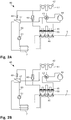
- the Figure 2A is a schematic representation of the air conditioner in cooling operation.
- the illustration shows the rear air conditioning unit 40, which, in addition to the air conditioning of the passenger compartment 5, also for providing a cooling fluid for cooling the driving battery 7 responsible is.
- the air conditioner 40 comprises a first heat exchanger 41 with an associated blower 42, which draws in outside air and guides it through aluminum fins of the first heat exchanger 41.
- the first heat exchanger is connected at its first end to a compressor 44 via a changeover valve 43.
- the changeover valve 43 is also connected via a line to the first end of a second heat exchanger 45 and via a third heat exchanger 47 and an expansion valve 48 to the second end of the first heat exchanger 41.
- the second end of the first heat exchanger 41 is finally connected to the second end of the second heat exchanger 45 via a further expansion valve 49.
- the second heat exchanger 45 is also equipped with a blower 46, by means of which air is sucked in, passed through the aluminum fins of the second heat exchanger and can be discharged into the passenger compartment 5.
- the heating tubes of a fourth heat exchanger 55 which are connected to the water heater via lines, are also guided through these aluminum fins. Since this heat exchanger 55 is not used in cooling operation, the corresponding elements are shown in broken lines (cf. Figure 2B ).
- the third heat exchanger 47 is connected to a coolant circuit 50 for the drive battery 7. This has its own pump 51.
- cooling mode which in the Figure 2A is shown, the changeover valve 43 is switched such that coolant compressed by the compressor 44 is directed to the first end of the first heat exchanger 41 and that evaporated coolant or recirculated coolant from the third heat exchanger 47 is returned to the compressor 44 in the second heat exchanger 45.
- the mode of operation is as follows: The initially liquid coolant passes the second heat exchanger 45 and is evaporated therein, the air passing through the second heat exchanger 45 and directed into the passenger compartment 5 being cooled. The coolant then passes through the changeover valve 43 into the compressor 44 and is compressed there. The condensation then takes place in the first heat exchanger 41, heat being given off to the surroundings. The condensed coolant will then fed to the two expansion valves 48, 49, where it expands and thus cools down. A portion of the coolant is then fed back to the second heat exchanger 45. The other portion passes through the third heat exchanger 47 and cools the coolant in the coolant circuit 50 for the traction battery 7.
- the Figure 2B is a schematic representation of the air conditioner in heating mode.
- the changeover valve 43 is switched in this operating mode in such a way that coolant compressed by the compressor 44 is conducted to the first end of the second heat exchanger 45 and that coolant expanded in the expansion valve 49 and recirculated coolant from the third heat exchanger 47 are fed back to the compressor 44 via the first heat exchanger 41 .
- the mode of operation is as follows: heat is supplied to the coolant by means of a compressor 44, the heated coolant then emits heat to the passenger compartment 5 via the second heat exchanger 45. The coolant then passes through the expansion valve 49 and is thereby further cooled, so that it can absorb heat from the surroundings in the first heat exchanger 41. The coolant is then returned to the compressor 44.
- the air conditioner 40 thus functions as a heat pump with a reversed cycle.
- the driving battery 7 is cooled via a portion of the cooling liquid which has had heat removed in the second heat exchanger 45 and which is then fed to the third heat exchanger 47 via the expansion valve 48.
- water heated in the water heater can be supplied to the fourth heat exchanger 55, so that the air led into the passenger compartment 5 is further heated.
- the water heater is used in particular at lower outside temperatures. Above a certain lower limit temperature, icing of the first heat exchanger 41 threatens, moreover, the heating power of the heat pump alone is no longer sufficient to achieve a sufficient temperature in the passenger compartment.
- the additional heating of the supplied air by means of the fourth heat exchanger 55 also improves dehumidification of the air and thus reduces the internal fogging on the vehicle windows.
- the Figure 3 is a representation of the energy savings over the course of the year. It is based on a simulation and shows how much the required heating energy can be reduced by using the air conditioning units as a heat pump and infrared heating. The values refer to the climatic conditions in the Swiss plateau.
- the energy values shown on the vertical axis are given in kWh / km per vehicle.
- the horizontal axis shows the heating energy consumption 101.1 ... 12 for the months January-December and the average value 101.0 for the whole year above the zero line.
- the display begins with the month of December so that the winter months of December-February are displayed side by side.
- roof air conditioners without a heat pump function can also be used.
- Specific dimensions and characteristics of the components used can also be selected differently, in particular depending on the expansion of the passenger compartment to be air-conditioned and the expected climatic conditions.
- the invention creates a system for air conditioning a passenger compartment of a passenger bus, which system also functions economically at lower outside temperatures.
Landscapes
- Engineering & Computer Science (AREA)
- Physics & Mathematics (AREA)
- Thermal Sciences (AREA)
- Mechanical Engineering (AREA)
- Life Sciences & Earth Sciences (AREA)
- Sustainable Development (AREA)
- Sustainable Energy (AREA)
- Air-Conditioning For Vehicles (AREA)
Claims (10)
- Installation destinée à climatiser un habitacle (5) d'un bus de passagers (1), comprenant :a) au moins un climatiseur de toit (20, 40) pour générer sélectivement de l'air chauffé ou de l'air rafraîchi pour la climatisation de l'habitacle (5) ;b) un dispositif de chauffage (80) pour chauffer un agent caloporteur ;c) l'au moins un climatiseur de toit (20, 40) comportant un échangeur thermique en tant qu'élément chauffant pour la génération de l'air chauffé ;caractérisée en ce qued) l'installation comprend une installation de chauffage aux infrarouges (60) pour l'habitacle (5) ;
ete) le dispositif de chauffage (80) est relié avec l'échangeur thermique de l'au moins un climatiseur de toit (20, 40), de telle sorte que de l'agent caloporteur chauffé dans le dispositif de chauffage (80) puisse être alimenté vers l'échangeur thermique, un circuit supplémentaire pour l'agent caloporteur chauffé par le dispositif de chauffage (80) comportant des tubes chauffants qui dans l'échangeur thermique s'étendent en parallèle de tubes, lesquels conduisent un fluide tempéré par le climatiseur de toit (20, 40) et l'échangeur thermique de l'au moins un climatiseur de toit (20, 40) étant équipé d'un ventilateur (46) au moyen duquel de l'air se laisse aspirer, guider à travers des lamelles en aluminium de l'échangeur thermique et restituer dans un habitacle (5), les tubes chauffants pour l'agent caloporteur chauffé par le dispositif de chauffage (80) étant également guidés à travers lesdites lamelles en aluminium. - Installation selon la revendication 1, caractérisée en ce qu'en tant qu'agent caloporteur est utilisée de l'eau, en ce que le dispositif de chauffage (80) est un dispositif destiné à chauffer de l'eau et en ce que l'échangeur thermique est un échangeur thermique eau-air.
- Installation selon la revendication 1 ou 2, caractérisée en ce que l'au moins un climatiseur de toit (20, 40) est exploitable comme une pompe à chaleur.
- Installation selon l'une quelconque des revendications 1 à 3, comprenant un système de commande destiné à commander l'au moins un climatiseur de toit (20, 40), l'installation de chauffage aux infrarouges (60) et le dispositif de chauffage (80), le système de commande étant susceptible d'être amené au moins dans un premier mode de fonctionnement, dans lequel l'au moins un climatiseur de toit (20, 40) génère de l'air chauffé pour la climatisation de l'habitacle (5) et l'installation de chauffage aux infrarouges (60) est à l'arrêt, et dans un deuxième mode de fonctionnement dans lequel l'au moins un climatiseur de toit (20, 40) génère de l'air chauffé pour la climatisation de l'habitacle (5) et l'installation de chauffage aux infrarouges (60) est en marche.
- Installation selon la revendication 4, caractérisée en ce que le premier mode de fonctionnement ou le deuxième mode de fonctionnement sont activés en fonction d'une température extérieure et d'une disponibilité d'énergie.
- Installation selon l'une quelconque des revendications 1 à 5, caractérisée par un caisson frontal (90) destiné à climatiser une cabine du conducteur (4) et à désembuer un pare-brise.
- Installation selon la revendication 6, caractérisée en ce que pour chauffer la cabine du conducteur, le dispositif de chauffage (80) est relié avec le caisson frontal (90).
- Installation selon l'une quelconque des revendications 1 à 7, caractérisée par un circuit de refroidissement pour des accumulateurs de traction (7) placés sur le toit du bus de passagers, le circuit de refroidissement étant relié avec au moins l'un des climatiseurs de toit.
- Installation selon l'une quelconque des revendications 1 à 8, caractérisée en ce qu'une puissance de chauffage totale requise pour chauffer l'habitacle est mise à disposition par l'au moins un climatiseur de toit (20, 40), le dispositif de chauffage (80) et l'installation de chauffage aux infrarouges (60).
- Bus de passagers (1) pourvu d'une installation destinée à climatiser un habitacle (5) selon l'une quelconque des revendications 1 à 9.
Priority Applications (1)
| Application Number | Priority Date | Filing Date | Title |
|---|---|---|---|
| EP16181755.6A EP3275706B1 (fr) | 2016-07-28 | 2016-07-28 | Installation de climatisation d'un habitacle d'un bus a passagers |
Applications Claiming Priority (1)
| Application Number | Priority Date | Filing Date | Title |
|---|---|---|---|
| EP16181755.6A EP3275706B1 (fr) | 2016-07-28 | 2016-07-28 | Installation de climatisation d'un habitacle d'un bus a passagers |
Publications (2)
| Publication Number | Publication Date |
|---|---|
| EP3275706A1 EP3275706A1 (fr) | 2018-01-31 |
| EP3275706B1 true EP3275706B1 (fr) | 2020-04-08 |
Family
ID=56557553
Family Applications (1)
| Application Number | Title | Priority Date | Filing Date |
|---|---|---|---|
| EP16181755.6A Active EP3275706B1 (fr) | 2016-07-28 | 2016-07-28 | Installation de climatisation d'un habitacle d'un bus a passagers |
Country Status (1)
| Country | Link |
|---|---|
| EP (1) | EP3275706B1 (fr) |
Cited By (1)
| Publication number | Priority date | Publication date | Assignee | Title |
|---|---|---|---|---|
| EP4703229A1 (fr) * | 2024-07-30 | 2026-03-04 | SpeedInnov | Véhicule ferroviaire avec un système de ventilation d'urgence |
Families Citing this family (3)
| Publication number | Priority date | Publication date | Assignee | Title |
|---|---|---|---|---|
| JP7207202B2 (ja) * | 2019-06-28 | 2023-01-18 | トヨタ自動車株式会社 | 車両 |
| JP2022038655A (ja) * | 2020-08-27 | 2022-03-10 | 三菱電機株式会社 | 車両用結露検出装置、車両用空調装置、及び車両用結露検出方法 |
| EP3995334B1 (fr) | 2020-11-06 | 2025-01-22 | Carrosserie Hess AG | Bus électrique |
Family Cites Families (5)
| Publication number | Priority date | Publication date | Assignee | Title |
|---|---|---|---|---|
| DE4138355C2 (de) * | 1991-11-21 | 1994-05-11 | Webasto Klimatech Gmbh | Verfahren und Einrichtung zur Klimatisierung des Innenraumes eines Omnibusses |
| SE0600471L (sv) * | 2006-03-02 | 2007-01-16 | Uwe Verken Ab | Fordonsstationär klimatkontroll |
| US9517681B2 (en) | 2009-08-21 | 2016-12-13 | Martin A. Alpert | Apparatus and method for radiant heating and cooling for vehicles |
| DE102011107081A1 (de) * | 2011-07-11 | 2013-01-17 | Spheros Gmbh | Verfahren und Vorrichtung zum Konditionieren der Luft im Innenraum eines Fahrzeuges |
| DE102014018416A1 (de) | 2014-12-11 | 2015-06-18 | Daimler Ag | Innenraumheizeinrichtung für ein Fahrzeug, Fahrzeug mit einer solchen Innenraumheizeinrichtung, und Verfahren zum Heizen eines Fahrzeugs-Innenraums |
-
2016
- 2016-07-28 EP EP16181755.6A patent/EP3275706B1/fr active Active
Non-Patent Citations (1)
| Title |
|---|
| None * |
Cited By (1)
| Publication number | Priority date | Publication date | Assignee | Title |
|---|---|---|---|---|
| EP4703229A1 (fr) * | 2024-07-30 | 2026-03-04 | SpeedInnov | Véhicule ferroviaire avec un système de ventilation d'urgence |
Also Published As
| Publication number | Publication date |
|---|---|
| EP3275706A1 (fr) | 2018-01-31 |
Similar Documents
| Publication | Publication Date | Title |
|---|---|---|
| EP3703991B1 (fr) | Véhicule guidé, système de refroidissement d'un dispositif de stockage d'énergie dudit véhicule guidé, et procédé de commande dudit système | |
| DE102018214736A1 (de) | Verfahren zum Klimatisieren eines batterie-elektrischen Fahrzeugs | |
| DE10242464B4 (de) | Vorrichtung zur Klimatisierung eines Fahrzeuginnenraums | |
| EP2596978B1 (fr) | Véhicule thermique doté d'une cellule tempérée, isolée thermiquement | |
| DE112020002633B4 (de) | Fahrzeug-Klimaanlage | |
| EP3275706B1 (fr) | Installation de climatisation d'un habitacle d'un bus a passagers | |
| DE10019571A1 (de) | Klimaanlage für ein Nutzkraftfahrzeug | |
| EP2625051B1 (fr) | Dispositif de climatisation et procédé pour la climatisation d'un espace intérieur et/ou d'au moins une pièce d'un véhicule électrique | |
| DE102020103340A1 (de) | Abtausystem mit auf einer wärmepumpe basierendem wärmetauscher mit einem sekundären kühlmittelkreislauf für ein kraftfahrzeug | |
| DE3532463A1 (de) | Heiz- und/oder klimaanlage fuer kraftfahrzeuge | |
| DE102013225839A1 (de) | Klimatisierungssystem und -verfahren für eine Hochspannungsbatterie eines Fahrzeuges | |
| WO2006082082A1 (fr) | Systeme de climatisation pour vehicule automobile | |
| WO2020156865A1 (fr) | Véhicule, en particulier véhicule à moteur, doté d'un dispositif de thermorégulation pour assurer la thermorégulation d'un espace intérieur du véhicule | |
| DE102023136513A1 (de) | Wärmemanagementsystem für ein fahrzeug | |
| DE102010026101B4 (de) | Heizungs- und Klimatisierungseinrichtung | |
| DE102018124748A1 (de) | Mehrzonenklimaanlage für Fahrzeuge | |
| DE102007039195B4 (de) | Anordnung zum Klimatisieren eines Fahrzeugs | |
| DE102018211559B4 (de) | Fahrzeug mit einer Klimatisierungsvorrichtung zum Erwärmen und Kühlen eines elektrischen Energiespeichers | |
| EP3628517B1 (fr) | Climatiseur modulaire pour un véhicule automobile | |
| DE102020003813A1 (de) | Fahrzeug | |
| DE102007046663A1 (de) | Klimaanlage und Verfahren zur Temperatureinstellung | |
| DE102007023249A1 (de) | Aufdachklimaanlage für ein Fahrzeug, insbesondere einen Omnibus | |
| WO2019241813A1 (fr) | Procédé de refroidissement d'une cabine de véhicule | |
| EP4054887B1 (fr) | Véhicule ferroviaire doté d'un ensemble de refroidissement et de climatisation | |
| DE102016204986A1 (de) | Klimatisierungsvorrichtung für ein Fahrzeug |
Legal Events
| Date | Code | Title | Description |
|---|---|---|---|
| PUAI | Public reference made under article 153(3) epc to a published international application that has entered the european phase |
Free format text: ORIGINAL CODE: 0009012 |
|
| STAA | Information on the status of an ep patent application or granted ep patent |
Free format text: STATUS: THE APPLICATION HAS BEEN PUBLISHED |
|
| AK | Designated contracting states |
Kind code of ref document: A1 Designated state(s): AL AT BE BG CH CY CZ DE DK EE ES FI FR GB GR HR HU IE IS IT LI LT LU LV MC MK MT NL NO PL PT RO RS SE SI SK SM TR |
|
| AX | Request for extension of the european patent |
Extension state: BA ME |
|
| STAA | Information on the status of an ep patent application or granted ep patent |
Free format text: STATUS: REQUEST FOR EXAMINATION WAS MADE |
|
| 17P | Request for examination filed |
Effective date: 20180321 |
|
| RBV | Designated contracting states (corrected) |
Designated state(s): AL AT BE BG CH CY CZ DE DK EE ES FI FR GB GR HR HU IE IS IT LI LT LU LV MC MK MT NL NO PL PT RO RS SE SI SK SM TR |
|
| STAA | Information on the status of an ep patent application or granted ep patent |
Free format text: STATUS: EXAMINATION IS IN PROGRESS |
|
| 17Q | First examination report despatched |
Effective date: 20180907 |
|
| GRAP | Despatch of communication of intention to grant a patent |
Free format text: ORIGINAL CODE: EPIDOSNIGR1 |
|
| STAA | Information on the status of an ep patent application or granted ep patent |
Free format text: STATUS: GRANT OF PATENT IS INTENDED |
|
| INTG | Intention to grant announced |
Effective date: 20191106 |
|
| GRAS | Grant fee paid |
Free format text: ORIGINAL CODE: EPIDOSNIGR3 |
|
| GRAA | (expected) grant |
Free format text: ORIGINAL CODE: 0009210 |
|
| STAA | Information on the status of an ep patent application or granted ep patent |
Free format text: STATUS: THE PATENT HAS BEEN GRANTED |
|
| AK | Designated contracting states |
Kind code of ref document: B1 Designated state(s): AL AT BE BG CH CY CZ DE DK EE ES FI FR GB GR HR HU IE IS IT LI LT LU LV MC MK MT NL NO PL PT RO RS SE SI SK SM TR |
|
| REG | Reference to a national code |
Ref country code: CH Ref legal event code: EP Ref country code: AT Ref legal event code: REF Ref document number: 1253892 Country of ref document: AT Kind code of ref document: T Effective date: 20200415 |
|
| REG | Reference to a national code |
Ref country code: DE Ref legal event code: R096 Ref document number: 502016009438 Country of ref document: DE |
|
| REG | Reference to a national code |
Ref country code: IE Ref legal event code: FG4D Free format text: LANGUAGE OF EP DOCUMENT: GERMAN |
|
| REG | Reference to a national code |
Ref country code: CH Ref legal event code: NV Representative=s name: KELLER AND PARTNER PATENTANWAELTE AG, CH |
|
| REG | Reference to a national code |
Ref country code: NL Ref legal event code: MP Effective date: 20200408 |
|
| REG | Reference to a national code |
Ref country code: LT Ref legal event code: MG4D |
|
| REG | Reference to a national code |
Ref country code: CH Ref legal event code: PFA Owner name: CARROSSERIE HESS AG, CH Free format text: FORMER OWNER: CARROSSERIE HESS AG, CH |
|
| PG25 | Lapsed in a contracting state [announced via postgrant information from national office to epo] |
Ref country code: IS Free format text: LAPSE BECAUSE OF FAILURE TO SUBMIT A TRANSLATION OF THE DESCRIPTION OR TO PAY THE FEE WITHIN THE PRESCRIBED TIME-LIMIT Effective date: 20200808 Ref country code: PT Free format text: LAPSE BECAUSE OF FAILURE TO SUBMIT A TRANSLATION OF THE DESCRIPTION OR TO PAY THE FEE WITHIN THE PRESCRIBED TIME-LIMIT Effective date: 20200817 Ref country code: NL Free format text: LAPSE BECAUSE OF FAILURE TO SUBMIT A TRANSLATION OF THE DESCRIPTION OR TO PAY THE FEE WITHIN THE PRESCRIBED TIME-LIMIT Effective date: 20200408 Ref country code: LT Free format text: LAPSE BECAUSE OF FAILURE TO SUBMIT A TRANSLATION OF THE DESCRIPTION OR TO PAY THE FEE WITHIN THE PRESCRIBED TIME-LIMIT Effective date: 20200408 Ref country code: NO Free format text: LAPSE BECAUSE OF FAILURE TO SUBMIT A TRANSLATION OF THE DESCRIPTION OR TO PAY THE FEE WITHIN THE PRESCRIBED TIME-LIMIT Effective date: 20200708 Ref country code: GR Free format text: LAPSE BECAUSE OF FAILURE TO SUBMIT A TRANSLATION OF THE DESCRIPTION OR TO PAY THE FEE WITHIN THE PRESCRIBED TIME-LIMIT Effective date: 20200709 Ref country code: SE Free format text: LAPSE BECAUSE OF FAILURE TO SUBMIT A TRANSLATION OF THE DESCRIPTION OR TO PAY THE FEE WITHIN THE PRESCRIBED TIME-LIMIT Effective date: 20200408 Ref country code: FI Free format text: LAPSE BECAUSE OF FAILURE TO SUBMIT A TRANSLATION OF THE DESCRIPTION OR TO PAY THE FEE WITHIN THE PRESCRIBED TIME-LIMIT Effective date: 20200408 |
|
| PG25 | Lapsed in a contracting state [announced via postgrant information from national office to epo] |
Ref country code: HR Free format text: LAPSE BECAUSE OF FAILURE TO SUBMIT A TRANSLATION OF THE DESCRIPTION OR TO PAY THE FEE WITHIN THE PRESCRIBED TIME-LIMIT Effective date: 20200408 Ref country code: LV Free format text: LAPSE BECAUSE OF FAILURE TO SUBMIT A TRANSLATION OF THE DESCRIPTION OR TO PAY THE FEE WITHIN THE PRESCRIBED TIME-LIMIT Effective date: 20200408 Ref country code: BG Free format text: LAPSE BECAUSE OF FAILURE TO SUBMIT A TRANSLATION OF THE DESCRIPTION OR TO PAY THE FEE WITHIN THE PRESCRIBED TIME-LIMIT Effective date: 20200708 Ref country code: RS Free format text: LAPSE BECAUSE OF FAILURE TO SUBMIT A TRANSLATION OF THE DESCRIPTION OR TO PAY THE FEE WITHIN THE PRESCRIBED TIME-LIMIT Effective date: 20200408 |
|
| PG25 | Lapsed in a contracting state [announced via postgrant information from national office to epo] |
Ref country code: AL Free format text: LAPSE BECAUSE OF FAILURE TO SUBMIT A TRANSLATION OF THE DESCRIPTION OR TO PAY THE FEE WITHIN THE PRESCRIBED TIME-LIMIT Effective date: 20200408 |
|
| REG | Reference to a national code |
Ref country code: DE Ref legal event code: R097 Ref document number: 502016009438 Country of ref document: DE |
|
| PG25 | Lapsed in a contracting state [announced via postgrant information from national office to epo] |
Ref country code: SM Free format text: LAPSE BECAUSE OF FAILURE TO SUBMIT A TRANSLATION OF THE DESCRIPTION OR TO PAY THE FEE WITHIN THE PRESCRIBED TIME-LIMIT Effective date: 20200408 Ref country code: EE Free format text: LAPSE BECAUSE OF FAILURE TO SUBMIT A TRANSLATION OF THE DESCRIPTION OR TO PAY THE FEE WITHIN THE PRESCRIBED TIME-LIMIT Effective date: 20200408 Ref country code: ES Free format text: LAPSE BECAUSE OF FAILURE TO SUBMIT A TRANSLATION OF THE DESCRIPTION OR TO PAY THE FEE WITHIN THE PRESCRIBED TIME-LIMIT Effective date: 20200408 Ref country code: CZ Free format text: LAPSE BECAUSE OF FAILURE TO SUBMIT A TRANSLATION OF THE DESCRIPTION OR TO PAY THE FEE WITHIN THE PRESCRIBED TIME-LIMIT Effective date: 20200408 Ref country code: RO Free format text: LAPSE BECAUSE OF FAILURE TO SUBMIT A TRANSLATION OF THE DESCRIPTION OR TO PAY THE FEE WITHIN THE PRESCRIBED TIME-LIMIT Effective date: 20200408 Ref country code: IT Free format text: LAPSE BECAUSE OF FAILURE TO SUBMIT A TRANSLATION OF THE DESCRIPTION OR TO PAY THE FEE WITHIN THE PRESCRIBED TIME-LIMIT Effective date: 20200408 Ref country code: DK Free format text: LAPSE BECAUSE OF FAILURE TO SUBMIT A TRANSLATION OF THE DESCRIPTION OR TO PAY THE FEE WITHIN THE PRESCRIBED TIME-LIMIT Effective date: 20200408 |
|
| PLBE | No opposition filed within time limit |
Free format text: ORIGINAL CODE: 0009261 |
|
| STAA | Information on the status of an ep patent application or granted ep patent |
Free format text: STATUS: NO OPPOSITION FILED WITHIN TIME LIMIT |
|
| PG25 | Lapsed in a contracting state [announced via postgrant information from national office to epo] |
Ref country code: SK Free format text: LAPSE BECAUSE OF FAILURE TO SUBMIT A TRANSLATION OF THE DESCRIPTION OR TO PAY THE FEE WITHIN THE PRESCRIBED TIME-LIMIT Effective date: 20200408 Ref country code: MC Free format text: LAPSE BECAUSE OF FAILURE TO SUBMIT A TRANSLATION OF THE DESCRIPTION OR TO PAY THE FEE WITHIN THE PRESCRIBED TIME-LIMIT Effective date: 20200408 Ref country code: PL Free format text: LAPSE BECAUSE OF FAILURE TO SUBMIT A TRANSLATION OF THE DESCRIPTION OR TO PAY THE FEE WITHIN THE PRESCRIBED TIME-LIMIT Effective date: 20200408 |
|
| 26N | No opposition filed |
Effective date: 20210112 |
|
| GBPC | Gb: european patent ceased through non-payment of renewal fee |
Effective date: 20200728 |
|
| REG | Reference to a national code |
Ref country code: BE Ref legal event code: MM Effective date: 20200731 |
|
| PG25 | Lapsed in a contracting state [announced via postgrant information from national office to epo] |
Ref country code: FR Free format text: LAPSE BECAUSE OF NON-PAYMENT OF DUE FEES Effective date: 20200731 Ref country code: GB Free format text: LAPSE BECAUSE OF NON-PAYMENT OF DUE FEES Effective date: 20200728 Ref country code: LU Free format text: LAPSE BECAUSE OF NON-PAYMENT OF DUE FEES Effective date: 20200728 |
|
| PG25 | Lapsed in a contracting state [announced via postgrant information from national office to epo] |
Ref country code: BE Free format text: LAPSE BECAUSE OF NON-PAYMENT OF DUE FEES Effective date: 20200731 Ref country code: SI Free format text: LAPSE BECAUSE OF FAILURE TO SUBMIT A TRANSLATION OF THE DESCRIPTION OR TO PAY THE FEE WITHIN THE PRESCRIBED TIME-LIMIT Effective date: 20200408 |
|
| PG25 | Lapsed in a contracting state [announced via postgrant information from national office to epo] |
Ref country code: IE Free format text: LAPSE BECAUSE OF NON-PAYMENT OF DUE FEES Effective date: 20200728 |
|
| PG25 | Lapsed in a contracting state [announced via postgrant information from national office to epo] |
Ref country code: TR Free format text: LAPSE BECAUSE OF FAILURE TO SUBMIT A TRANSLATION OF THE DESCRIPTION OR TO PAY THE FEE WITHIN THE PRESCRIBED TIME-LIMIT Effective date: 20200408 Ref country code: MT Free format text: LAPSE BECAUSE OF FAILURE TO SUBMIT A TRANSLATION OF THE DESCRIPTION OR TO PAY THE FEE WITHIN THE PRESCRIBED TIME-LIMIT Effective date: 20200408 Ref country code: CY Free format text: LAPSE BECAUSE OF FAILURE TO SUBMIT A TRANSLATION OF THE DESCRIPTION OR TO PAY THE FEE WITHIN THE PRESCRIBED TIME-LIMIT Effective date: 20200408 |
|
| PG25 | Lapsed in a contracting state [announced via postgrant information from national office to epo] |
Ref country code: MK Free format text: LAPSE BECAUSE OF FAILURE TO SUBMIT A TRANSLATION OF THE DESCRIPTION OR TO PAY THE FEE WITHIN THE PRESCRIBED TIME-LIMIT Effective date: 20200408 |
|
| PGFP | Annual fee paid to national office [announced via postgrant information from national office to epo] |
Ref country code: DE Payment date: 20250722 Year of fee payment: 10 |
|
| PGFP | Annual fee paid to national office [announced via postgrant information from national office to epo] |
Ref country code: AT Payment date: 20250722 Year of fee payment: 10 |
|
| PGFP | Annual fee paid to national office [announced via postgrant information from national office to epo] |
Ref country code: CH Payment date: 20250801 Year of fee payment: 10 |