EP4054887B1 - Véhicule ferroviaire doté d'un ensemble de refroidissement et de climatisation - Google Patents
Véhicule ferroviaire doté d'un ensemble de refroidissement et de climatisation Download PDFInfo
- Publication number
- EP4054887B1 EP4054887B1 EP20824130.7A EP20824130A EP4054887B1 EP 4054887 B1 EP4054887 B1 EP 4054887B1 EP 20824130 A EP20824130 A EP 20824130A EP 4054887 B1 EP4054887 B1 EP 4054887B1
- Authority
- EP
- European Patent Office
- Prior art keywords
- heat exchanger
- coolant
- cooling
- refrigerant
- circuit
- Prior art date
- Legal status (The legal status is an assumption and is not a legal conclusion. Google has not performed a legal analysis and makes no representation as to the accuracy of the status listed.)
- Active
Links
Images


Classifications
-
- B—PERFORMING OPERATIONS; TRANSPORTING
- B60—VEHICLES IN GENERAL
- B60L—PROPULSION OF ELECTRICALLY-PROPELLED VEHICLES; SUPPLYING ELECTRIC POWER FOR AUXILIARY EQUIPMENT OF ELECTRICALLY-PROPELLED VEHICLES; ELECTRODYNAMIC BRAKE SYSTEMS FOR VEHICLES IN GENERAL; MAGNETIC SUSPENSION OR LEVITATION FOR VEHICLES; MONITORING OPERATING VARIABLES OF ELECTRICALLY-PROPELLED VEHICLES; ELECTRIC SAFETY DEVICES FOR ELECTRICALLY-PROPELLED VEHICLES
- B60L1/00—Supplying electric power to auxiliary equipment of vehicles
-
- B—PERFORMING OPERATIONS; TRANSPORTING
- B60—VEHICLES IN GENERAL
- B60H—ARRANGEMENTS OF HEATING, COOLING, VENTILATING OR OTHER AIR-TREATING DEVICES SPECIALLY ADAPTED FOR PASSENGER OR GOODS SPACES OF VEHICLES
- B60H1/00—Heating, cooling or ventilating devices
- B60H1/00357—Air-conditioning arrangements specially adapted for particular vehicles
- B60H1/00371—Air-conditioning arrangements specially adapted for particular vehicles for vehicles carrying large numbers of passengers, e.g. buses
-
- B—PERFORMING OPERATIONS; TRANSPORTING
- B60—VEHICLES IN GENERAL
- B60H—ARRANGEMENTS OF HEATING, COOLING, VENTILATING OR OTHER AIR-TREATING DEVICES SPECIALLY ADAPTED FOR PASSENGER OR GOODS SPACES OF VEHICLES
- B60H1/00—Heating, cooling or ventilating devices
- B60H1/32—Cooling devices
- B60H1/3204—Cooling devices using compression
- B60H1/3228—Cooling devices using compression characterised by refrigerant circuit configurations
- B60H1/32284—Cooling devices using compression characterised by refrigerant circuit configurations comprising two or more secondary circuits, e.g. at evaporator and condenser side
-
- B—PERFORMING OPERATIONS; TRANSPORTING
- B60—VEHICLES IN GENERAL
- B60L—PROPULSION OF ELECTRICALLY-PROPELLED VEHICLES; SUPPLYING ELECTRIC POWER FOR AUXILIARY EQUIPMENT OF ELECTRICALLY-PROPELLED VEHICLES; ELECTRODYNAMIC BRAKE SYSTEMS FOR VEHICLES IN GENERAL; MAGNETIC SUSPENSION OR LEVITATION FOR VEHICLES; MONITORING OPERATING VARIABLES OF ELECTRICALLY-PROPELLED VEHICLES; ELECTRIC SAFETY DEVICES FOR ELECTRICALLY-PROPELLED VEHICLES
- B60L3/00—Electric devices on electrically-propelled vehicles for safety purposes; Monitoring operating variables, e.g. speed, deceleration or energy consumption
- B60L3/0023—Detecting, eliminating, remedying or compensating for drive train abnormalities, e.g. failures within the drive train
- B60L3/0046—Detecting, eliminating, remedying or compensating for drive train abnormalities, e.g. failures within the drive train relating to electric energy storage systems, e.g. batteries or capacitors
-
- B—PERFORMING OPERATIONS; TRANSPORTING
- B60—VEHICLES IN GENERAL
- B60L—PROPULSION OF ELECTRICALLY-PROPELLED VEHICLES; SUPPLYING ELECTRIC POWER FOR AUXILIARY EQUIPMENT OF ELECTRICALLY-PROPELLED VEHICLES; ELECTRODYNAMIC BRAKE SYSTEMS FOR VEHICLES IN GENERAL; MAGNETIC SUSPENSION OR LEVITATION FOR VEHICLES; MONITORING OPERATING VARIABLES OF ELECTRICALLY-PROPELLED VEHICLES; ELECTRIC SAFETY DEVICES FOR ELECTRICALLY-PROPELLED VEHICLES
- B60L58/00—Methods or circuit arrangements for monitoring or controlling batteries or fuel cells, specially adapted for electric vehicles
- B60L58/10—Methods or circuit arrangements for monitoring or controlling batteries or fuel cells, specially adapted for electric vehicles for monitoring or controlling batteries
- B60L58/24—Methods or circuit arrangements for monitoring or controlling batteries or fuel cells, specially adapted for electric vehicles for monitoring or controlling batteries for controlling the temperature of batteries
-
- B—PERFORMING OPERATIONS; TRANSPORTING
- B60—VEHICLES IN GENERAL
- B60L—PROPULSION OF ELECTRICALLY-PROPELLED VEHICLES; SUPPLYING ELECTRIC POWER FOR AUXILIARY EQUIPMENT OF ELECTRICALLY-PROPELLED VEHICLES; ELECTRODYNAMIC BRAKE SYSTEMS FOR VEHICLES IN GENERAL; MAGNETIC SUSPENSION OR LEVITATION FOR VEHICLES; MONITORING OPERATING VARIABLES OF ELECTRICALLY-PROPELLED VEHICLES; ELECTRIC SAFETY DEVICES FOR ELECTRICALLY-PROPELLED VEHICLES
- B60L58/00—Methods or circuit arrangements for monitoring or controlling batteries or fuel cells, specially adapted for electric vehicles
- B60L58/10—Methods or circuit arrangements for monitoring or controlling batteries or fuel cells, specially adapted for electric vehicles for monitoring or controlling batteries
- B60L58/24—Methods or circuit arrangements for monitoring or controlling batteries or fuel cells, specially adapted for electric vehicles for monitoring or controlling batteries for controlling the temperature of batteries
- B60L58/26—Methods or circuit arrangements for monitoring or controlling batteries or fuel cells, specially adapted for electric vehicles for monitoring or controlling batteries for controlling the temperature of batteries by cooling
-
- B—PERFORMING OPERATIONS; TRANSPORTING
- B61—RAILWAYS
- B61C—LOCOMOTIVES; MOTOR RAILCARS
- B61C3/00—Electric locomotives or railcars
- B61C3/02—Electric locomotives or railcars with electric accumulators
-
- B—PERFORMING OPERATIONS; TRANSPORTING
- B61—RAILWAYS
- B61D—BODY DETAILS OR KINDS OF RAILWAY VEHICLES
- B61D27/00—Heating, cooling, ventilating, or air-conditioning
- B61D27/0018—Air-conditioning means, i.e. combining at least two of the following ways of treating or supplying air, namely heating, cooling or ventilating
-
- B—PERFORMING OPERATIONS; TRANSPORTING
- B60—VEHICLES IN GENERAL
- B60H—ARRANGEMENTS OF HEATING, COOLING, VENTILATING OR OTHER AIR-TREATING DEVICES SPECIALLY ADAPTED FOR PASSENGER OR GOODS SPACES OF VEHICLES
- B60H1/00—Heating, cooling or ventilating devices
- B60H1/00271—HVAC devices specially adapted for particular vehicle parts or components and being connected to the vehicle HVAC unit
- B60H1/00278—HVAC devices specially adapted for particular vehicle parts or components and being connected to the vehicle HVAC unit for the battery
-
- B—PERFORMING OPERATIONS; TRANSPORTING
- B60—VEHICLES IN GENERAL
- B60H—ARRANGEMENTS OF HEATING, COOLING, VENTILATING OR OTHER AIR-TREATING DEVICES SPECIALLY ADAPTED FOR PASSENGER OR GOODS SPACES OF VEHICLES
- B60H1/00—Heating, cooling or ventilating devices
- B60H1/00271—HVAC devices specially adapted for particular vehicle parts or components and being connected to the vehicle HVAC unit
- B60H2001/00307—Component temperature regulation using a liquid flow
Definitions
- the invention relates to a rail vehicle with an energy storage device in which electrical energy can be stored to supply a traction device of the rail vehicle, and a cooling device which serves to cool the energy storage device.
- the invention further relates to a cooling and air conditioning arrangement for a rail vehicle.
- Rail vehicles that are supplied with electrical energy via an external power supply, for example in the form of an overhead line or a third rail, are fundamentally dependent on the complete electrification of the route network.
- these rail vehicles In order to be able to use these rail vehicles on routes that are not fully electrified, they are increasingly being equipped with energy storage devices, so-called traction batteries.
- the electrical energy stored in these traction batteries is used to supply drive components and, if necessary, auxiliary systems of the rail vehicle while traveling on a non-electrified section of the route.
- the traction batteries are charged, for example, while traveling on an electrified section of the route or at special charging stations, which can be located in the area of stops in particular.
- a traction battery usually consists of a large number of electrically interconnected battery cells or modules of battery cells with high performance and energy density.
- the battery cells are within a to operate within a defined temperature range, whereby the temperature range depends in particular on the materials of the battery cells. Particularly at high ambient temperatures, cooling of the battery cells is therefore necessary in order to keep their temperature at a value within the defined temperature range. Battery cells also generate heat themselves during charging and discharging processes, which must be dissipated accordingly.
- the battery cells or modules are cooled by means of a cooling device, for example by means of heat sinks connected to the housings of the battery cells or cell modules. These heat sinks are arranged, for example, in a coolant circuit which dissipates heat from the battery cells or heat sinks by means of a circulating liquid coolant.
- a refrigeration machine based on the principle of a compression refrigeration machine can be provided for cooling the coolant itself, for example a water-based coolant.
- a refrigeration machine which is used exclusively to cool the traction battery, disadvantageously leads to high costs and, if integrated into the traction battery container, to an increased space requirement for the container on the rail vehicle.
- the first heat exchanger which is arranged in both the coolant circuit and the refrigerant circuit and can thus be flowed through by both coolant and refrigerant, is designed, for example, as a water/refrigerant heat exchanger. In the refrigerant circuit, this takes on the function of an evaporator, which is usually designed as an air/refrigerant heat exchanger for cooling an air conditioning air flow. In the first heat exchanger, the refrigerant, which was previously cooled to a low temperature and is in a liquid state, evaporates and thereby cools the circulating coolant in the coolant circuit.
- the second heat exchanger is connected to the first Due to unavoidable losses in the first heat exchanger, the air conditioning system is less efficient than the solution in the older patent application DE 10 2017 223 214 A1 thus less efficient, but this reduced efficiency is negligible compared to efficiency losses, for example when the refrigeration system is operated at reduced power. Furthermore, the coolant heated in the second heat exchanger by the forced air flow continues to have a sufficiently low temperature to subsequently cool the energy storage device, since the upper value of the temperature band for the operation of the energy storage device is above the comfort temperature range.
- the control device of the rail vehicle according to the invention serves to control the flow of the coolant in the coolant circuit, in particular with regard to efficient cooling of the energy storage device and air conditioning, in particular of a room.
- the control device also serves to control the air conditioning device and the coolant circuit.
- the cooling device serving to cool the energy storage device is connected downstream of the second heat exchanger serving for air conditioning in the flow direction of the coolant and/or connected in parallel thereto.
- the rail vehicle according to the invention has a third heat exchanger which is arranged in the coolant circuit, wherein the third heat exchanger is connected upstream of the first heat exchanger in the flow direction of the coolant and wherein the coolant can be cooled in the third heat exchanger by means of a forced cooling air flow.
- the rail vehicle further comprises a controllable first valve which is arranged in the coolant circuit and by means of which a flow of the coolant through the second heat exchanger can be controlled, and a controllable second valve which is arranged in the coolant circuit and by means of which a flow of the coolant can be controlled while bypassing the second heat exchanger.
- a seventh valve which can be controlled by the control device is preferably arranged in the coolant circuit of the traction device and by means of which the volume of the coolant flowing through the fifth heat exchanger can be regulated per unit of time.
- the air conditioning air flow serves to cool the space of the rail vehicle, the flow of the coolant through the fifth heat exchanger and the heating of the air conditioning air flow caused thereby can be prevented by means of the seventh valve.
- the refrigeration device further comprises a second refrigerant circuit in which a refrigerant can be circulated, and a sixth heat exchanger which is arranged in the coolant circuit and in the second refrigerant circuit, and in which the coolant can be cooled by means of the refrigerant in the second refrigerant circuit.
- the second refrigerant circuit can be implemented as a redundant refrigerant circuit, which ensures cooling of the energy storage device or air conditioning of the room in the event of a failure of the first refrigerant circuit and thus enables the rail vehicle to continue traveling, for example.
- the refrigerant circuits are designed in such a way that they only achieve maximum cooling of the coolant in the first and sixth heat exchangers when operated in parallel.
- one of the two refrigerant circuits can be deactivated by the control device, which advantageously reduces the electrical energy required to operate the refrigeration device.
- the sixth heat exchanger is designed, for example, as a water/refrigerant heat exchanger, which in turn has the function of an evaporator in the second refrigerant circuit.
- the refrigeration system may have additional refrigerant circuits designed accordingly.
- the seventh heat exchanger is connected in parallel to the fourth heat exchanger in the direction of the cooling air flow and the sixth heat exchanger is connected in parallel to the first heat exchanger in the flow direction of the coolant.
- the coolant circuit is separated in the flow direction of the coolant before the heat exchangers and rejoined behind them, so that the coolant flows in equal parts through the first and sixth heat exchangers.
- a controllable eighth valve can be connected upstream or downstream of the sixth heat exchanger in order to prevent the coolant from flowing in the sixth heat exchanger. prevent, for example, if the second refrigerant circuit is deactivated under the control of the control device.
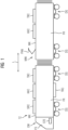
- FIG 1 shows a schematic side view of a rail vehicle, which is designed, for example, as a multiple unit TZ with a plurality of carriages for the transport of passengers, wherein only a first carriage in the form of an end carriage EW and a second carriage coupled to this carriage in the form of a middle carriage MW are shown.
- the multiple unit has two end carriages and a number of middle carriages, whereby this can alternatively consist of only two end carriages.
- the rail vehicle can have only a single carriage or be designed as a locomotive.
- the middle car MW In contrast to the end car EW, the middle car MW only has a passenger compartment FR. Passengers can enter and exit the passenger compartments FR of the cars EW, MW via doors (not shown) arranged in the side walls of the respective car body WK. Passengers can also get into the passenger compartment of a neighboring car via a car gangway. Such a car gangway is usually protected from environmental influences by a corrugated or bellows-type cover.
- a transformer is arranged in a first container TRC, for example, the primary winding of which can be connected to an overhead line (not shown) carrying high-voltage alternating current via a current collector or pantograph PAN arranged, for example, on the roof of the middle car MW.
- an energy storage device in the form of a traction battery TB is arranged, which is connected, for example, to a DC voltage intermediate circuit of the traction converter via a DC voltage controller.
- a corresponding container TBC is also arranged, for example, on the roof of the middle car MW. Distributing the traction battery across several cars of the rail vehicle can, on the one hand, advantageously increase the total storage capacity of the traction battery and thus the possible range of the multiple unit TZ under battery operation, and on the other hand achieve a more favorable distribution of the loads across the cars or bogies of the rail vehicle, for example in order not to exceed a specified maximum wheel load.
- additional containers KKC are arranged as examples, in which a respective cooling and air conditioning arrangement KKA is arranged, which is described in more detail in the following figures and which serves in particular to air-condition the respective passenger compartment FR of the end car EW and middle car MW or to air-condition the driver's cab FS of the end car EW.
- An evaporator such as that used in a compression refrigeration machine for air conditioning a passenger compartment according to the state of the art, is designed as an air/refrigerant heat exchanger.
- warm air from the passenger compartment and possibly additional fresh air from the vehicle's surroundings is passed through the evaporator with the help of a blower or one or more fans, in which the liquid refrigerant evaporates and thus cools the air flowing through. This is then fed to the passenger compartment as air conditioning air flow.
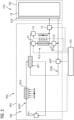
- the first heat exchanger WT1 in the first refrigerant circuit KAM1 differs from such a known evaporator in that it is not designed as an air/refrigerant heat exchanger, but is designed as a water/refrigerant heat exchanger. This is designed, for example, as a plate heat exchanger.
- the first heat exchanger WT1 is not only arranged in the first refrigerant circuit KAM1, but also in a coolant circuit KUM, in which a liquid coolant circulates. In the first heat exchanger WT1, the coolant in the liquid state evaporates due to the coolant flowing through it, which in turn cools it down.
- the cooling and air conditioning arrangement KKA thus also comprises a coolant circuit KUM, wherein the cooling device KUE arranged in the coolant circuit KUM, as in the FIG 2 shown, for example, is arranged outside the container KKC.
- the coolant cooled in the first heat exchanger WT1 can be fed to the cooling device KUE in the container TBC of the energy storage arrangement ESA and serves, as already described above, to cool the battery cells or modules of the traction battery TB.
- the coolant is circulated, for example, by means of a suitably designed coolant pump KMP arranged in the coolant circuit KUM. This is controlled by the control device STE, whereby its delivery rate can be controlled, whereby the control device STE can also simply switch the coolant pump KMP on or off.
- the coolant circuit KUM additionally has an expansion tank (not shown), which ensures that the coolant circuit is permanently completely filled with liquid coolant and within a permissible pressure range.
- the components arranged in the coolant circuit KUM are also connected to one another by means of suitable lines, pipes or hoses.
- the further function of the evaporator in a compression refrigeration machine namely air conditioning of a passenger compartment FR and/or a driver's cab FS of the multiple unit TZ by means of an air flow forced through the evaporator, is taken over by a second heat exchanger WT2.
- This is designed as an air/water heat exchanger, arranged in the coolant circuit KUM and, in the flow direction of the coolant, downstream of the first heat exchanger WT1.
- fresh air and/or circulating air from the passenger compartment supplied from the environment is guided through the second heat exchanger WT2 and cooled therein by the circulating coolant.
- the air cooled in this way is supplied to the passenger compartment as an air conditioning air flow, for example via fresh air ducts arranged in the interior ceiling area of the car and air outlets at suitable points on the interior ceiling.
- a plurality of valves V1 to V4 that can be controlled by the control device STE are provided. These enable in particular a flexible and situation-dependent control of the cooling of the traction battery TB as well as the passenger compartment by the control device STE.
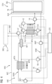
- FIG 3 Based on the above-mentioned FIG 2 a further embodiment of a cooling and air conditioning arrangement KKA.
- a third heat exchanger WT3 is additionally arranged in the coolant circuit KUM, which is connected upstream of the first heat exchanger WT1 in the flow direction of the coolant.
- the third heat exchanger WT3 is designed, for example, as an air/water heat exchanger in which the circulating coolant can be cooled by means of a forced cooling air flow.
- the third heat exchanger WT3 is arranged in such a way that the forced cooling air flow of the fourth heat exchanger WT4 of the refrigeration device KAE can flow through it.
- the fifth valve V5 and the sixth valve V6 can also be controlled by the control unit STE in such a way that the coolant flows exclusively via the third heat exchanger WT3 or exclusively via the parallel branch.
- a maximum cooling capacity for cooling the coolant can be achieved by means of the third heat exchanger WT3, while the coolant circuit KUM, when the fifth valve V5 is completely closed and the sixth valve V6 is opened, corresponds to the cooling capacity explained above.
- FIG 2 corresponds.
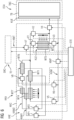
- FIG 4 shows based on the above explained FIG 3 a further embodiment of a cooling and air conditioning arrangement KKA.
- the other components explained below can, however, be used in the same way in the cooling and air conditioning device KKA of the FIG 2 be realized.
- one of the refrigerant circuits KAM1 or KAM2 can be deactivated while the other is operated in an energy-efficient range. If both refrigerant circuits are designed for maximum cooling capacity, the active refrigerant circuit would have to be operated in a partial load range, which is known to be energy-inefficient, particularly in compression refrigerant systems. The use of additional supplementary refrigerant circuits is also possible, particularly to increase the maximum cooling capacity.
- the sixth heat exchanger WT6 is, according to the embodiment of the FIG 5 in the coolant circuit KUM, in the flow direction of the coolant, upstream of the first heat exchanger WT1. This means that the circulating coolant first flows through the sixth heat exchanger WT6 and then through the first heat exchanger WT1 and is cooled in each of these, depending on the operation of the refrigerant circuits KAM1, KAM2.
- a seventh heat exchanger WT7 is arranged in the second refrigerant circuit KAM2 and, corresponding to the fourth heat exchanger WT4 in the first refrigerant circuit KAM1, is designed as an air/refrigerant heat exchanger. This thus takes on the function of a condenser or condenser in the second refrigerant circuit KAM2.
- the seventh heat exchanger WT7 is arranged in such a way that the forced cooling air flow can flow through it, whereby it is connected to the fourth Heat exchanger WT4 is connected downstream in the direction of the forced cooling air flow.
- the forced cooling air flow first flows through the third heat exchanger WT3, if such is arranged in the coolant circuit KUM, then the fourth heat exchanger WT4 and finally the seventh heat exchanger WT7 and is further heated in each of the heat exchangers.
- the seventh WT7 and the fourth heat exchanger WT4 are implemented as separate components, but alternatively they can also be implemented as a single component and in particular in a common housing.
- the third heat exchanger WT3 in particular can also be implemented in the common housing.
- the described arrangement of the sixth heat exchanger WT6 relative to the first heat exchanger WT1 in the coolant circuit KUM and of the seventh heat exchanger WT7 relative to the fourth heat exchanger WT4 in the cooling air flow means that when both refrigerant circuits KAM1, KAM2 are operated in parallel, the condensation and evaporation of the refrigerant takes place at different temperature levels.
- the temperature level of the refrigerant in the second refrigerant circuit KAM2 is higher than the temperature level of the refrigerant in the first refrigerant circuit KAM1.
- the circulating coolant is accordingly pre-cooled in the sixth heat exchanger WT6 using the refrigerant with the higher temperature and further cooled in the downstream first heat exchanger WT1 using the refrigerant with the lower temperature. This reduces exergy losses that arise due to a high temperature difference between the refrigerant and the coolant in a heat exchanger, thereby advantageously increasing the efficiency of cooling the coolant.
- FIG 6 shows a FIG 5 alternative design of the refrigeration device KAE of a cooling and air conditioning arrangement KKA designed according to the invention. This design is also based on the design of the FIG 4 , but can also be used in the cooling and air conditioning system KKA of the FIG 2 or 3 must be realized.
- the second refrigerant circuit KAM2 in the FIG 6 differs from the second refrigerant circuit KAM2 explained above of the FIG 5 by the respective arrangement of the sixth WT6 and seventh heat exchanger WT7 relative to the first WT1 or fourth heat exchanger WT4 of the first refrigerant circuit KAM1.
- the sixth heat exchanger WT6 is arranged in the coolant circuit KUM parallel to the first heat exchanger WT1 and the seventh heat exchanger WT7 is arranged in the cooling air flow parallel to the fourth heat exchanger WT4.
- a controllable valve can also be connected upstream or downstream of the first heat exchanger WT1, which is arranged parallel in the coolant circuit KUM, in order to regulate the flow of the coolant through the first heat exchanger WT1 accordingly by the control device STE.
- an optimal operation of the various components of the cooling and air conditioning arrangement KKA can be achieved, particularly with regard to energy consumption.
- Energy-efficient cooling and air conditioning is essential for rail vehicles whose main or exclusive Energy source is a traction battery, since inefficient operation of auxiliary systems or ancillary units, which include cooling and air conditioning systems, leads to a reduction in the range that can be achieved with electrical energy stored in the traction battery or requires an increase in the capacity of the traction battery.
Landscapes
- Engineering & Computer Science (AREA)
- Mechanical Engineering (AREA)
- Power Engineering (AREA)
- Transportation (AREA)
- Life Sciences & Earth Sciences (AREA)
- Sustainable Development (AREA)
- Sustainable Energy (AREA)
- Physics & Mathematics (AREA)
- Thermal Sciences (AREA)
- Air-Conditioning For Vehicles (AREA)
- Cooling, Air Intake And Gas Exhaust, And Fuel Tank Arrangements In Propulsion Units (AREA)
Claims (12)
- Véhicule (TZ) ferroviaire, comportant au moins :- un accumulateur (TB) d'énergie, dans lequel de l'énergie électrique pour l'alimentation d'un dispositif (TE) de traction peut être emmagasinée,- un dispositif (KUE) de refroidissement, qui est monté dans un circuit (KUM) de fluide de refroidissement et qui sert au refroidissement de l'accumulateur (TB) d'énergie, dans lequel un fluide de refroidissement liquide peut circuler dans le circuit (KUM) de fluide de refroidissement,- un dispositif (KAE) frigorifique ayant un premier circuit (KAM1) de fluide frigorifique, dans lequel un fluide frigorifique peut circuler,- un premier échangeur de chaleur (WT1), qui est monté dans le circuit (KUM) de fluide de refroidissement et dans le circuit (KAM1) de fluide frigorifique et dans lequel le fluide de refroidissement peut être refroidi au moyen du fluide frigorifique,- un dispositif (KLE) de conditionnement d'air ayant un deuxième échangeur de chaleur (WT2), dans lequel un espace (FS, FR) pouvant être utilisé par une personne peut être conditionné au moyen d'un courant d'air forcé de conditionnement d'air passant dans le deuxième échangeur de chaleur (WT2), et- un dispositif (STE) de commande,dans lequelle deuxième échangeur de chaleur (WT2) est monté exclusivement dans le circuit (KUM) de fluide de refroidissement et est monté, dans le sens d'écoulement du fluide de refroidissement, en aval du premier échangeur de chaleur (WT1),caractérisé en ce quele dispositif (KAE) frigorifique comporte en outre :- un deuxième circuit (KAM2) de fluide frigorifique, dans lequel un fluide frigorifique peut circuler, et- un sixième échangeur de chaleur (WT6), qui est monté dans le circuit (KUM) de fluide de refroidissement et dans le deuxième circuit (KAM2) de fluide frigorifique et dans lequel le fluide de refroidissement peut être refroidi au moyen du fluide frigorifique dans le deuxième circuit (KAM2) de fluide frigorifique.
- Véhicule ferroviaire suivant la revendication 1, caractérisé en ce que
le dispositif (KUE) de refroidissement est monté, dans le sens d'écoulement du fluide de refroidissement, en aval du deuxième échangeur de chaleur (WT2) et/ou est monté en parallèle avec celui-ci. - Véhicule ferroviaire suivant la revendication 1 ou 2, comportant en outre :
un troisième échangeur de chaleur (WT3), qui est monté dans le circuit (KUM) de fluide de refroidissement, dans lequel le troisième échangeur de chaleur (WT3) est monté, dans le sens d'écoulement du fluide de refroidissement, en amont du premier échangeur de chaleur (WT1) et dans lequel le fluide de refroidissement peut être refroidi dans le troisième échangeur de chaleur (WT3) au moyen d'un courant d'air forcé de refroidissement. - Véhicule ferroviaire suivant la revendication 3, caractérisé en ce que
le dispositif (KAE) frigorifique a un quatrième échangeur de chaleur (WT4), qui est monté dans le premier circuit (KAM1) de fluide frigorifique, dans lequel le fluide frigorifique peut être refroidi dans le quatrième échangeur de chaleur (WT4) au moyen d'un courant d'air forcé de refroidissement et dans lequel le quatrième échangeur de chaleur (WT4) est monté, dans le sens du courant d'air de refroidissement, en aval du troisième échangeur de chaleur (WT3). - Véhicule ferroviaire suivant l'une des revendications précédentes, comportant en outre :- une première soupape (V1) qui peut être commandée, qui est montée dans le circuit (KUM) de fluide de refroidissement et au moyen de laquelle un écoulement du fluide de refroidissement dans le deuxième échangeur de chaleur (WT2) peut être commandé, et- une deuxième soupape (V2), qui peut être commandée, qui est montée dans le circuit (KUM) de fluide de refroidissement et au moyen de laquelle un écoulement du fluide de refroidissement contournant le deuxième échangeur de chaleur (WT2) peut être commandé.
- Véhicule ferroviaire suivant l'une des revendications précédentes, comportant en outre :une troisième soupape (V3), qui peut être commandée, qui est montée dans le circuit (KUM) de fluide de refroidissement et qui est montée, dans le sens d'écoulement du fluide de refroidissement, en aval du deuxième échangeur de chaleur (WT2) et au moyen de laquelle un écoulement du fluide de refroidissement contournant le dispositif (KUE) de refroidissement peut être commandé, etune quatrième soupape (V4), qui peut être commandée, qui est montée dans le circuit (KUM) de fluide de refroidissement et qui est montée en amont ou en aval du dispositif (KUE) de refroidissement, dans le sens d'écoulement du fluide de refroidissement et au moyen de laquelle un écoulement du fluide de refroidissement dans le dispositif (KUE) de refroidissement peut être commandé.
- Véhicule ferroviaire suivant l'une des revendications 3 ou 4, comportant en outre :- une cinquième soupape (V5), qui peut être commandée, qui est montée dans le circuit (KUM) de fluide de refroidissement et qui est montée, dans le sens d'écoulement du fluide de refroidissement, en amont du troisième échangeur de chaleur (WT3) et au moyen de laquelle un écoulement du fluide de refroidissement dans le troisième échangeur de chaleur (WT3) peut être commandé, et- une sixième soupape (V6), qui peut être commandée, qui est montée dans le circuit (KUM) de fluide de refroidissement et au moyen de laquelle un écoulement du fluide de refroidissement contournant le troisième échangeur de chaleur (WT3) peut être commandé.
- Véhicule ferroviaire suivant l'une des revendications précédentes,
caractérisé en ce que
le dispositif (KLE) de conditionnement d'air comporte en outre : un cinquième échangeur de chaleur (WT5), qui est monté, dans le sens du courant d'air forcé de conditionnement d'air, en aval du deuxième échangeur de chaleur (WT2) et qui est monté dans un circuit de fluide de refroidissement du dispositif (TE) de traction. - Véhicule ferroviaire suivant les revendications 1 et 4, caractérisé en ce que
le dispositif (KAE) frigorifique comporte en outre :
un septième échangeur de chaleur (WT7), qui est monté dans le deuxième circuit (KAM2) de fluide frigorifique, dans lequel le fluide frigorifique peut être refroidi dans le septième échangeur de chaleur (WT7) au moyen du courant d'air forcé de refroidissement. - Véhicule ferroviaire suivant la revendication 9, caractérisé en ce que
le septième échangeur de chaleur (WT7) est monté, dans le sens du courant d'air de refroidissement, en aval du quatrième échangeur de chaleur (WT4) et le sixième échangeur de chaleur (WT6) est monté, dans le sens d'écoulement du fluide de refroidissement, en amont du premier échangeur de chaleur (WT1). - Véhicule ferroviaire suivant la revendication 9, caractérisé en ce que
le septième échangeur de chaleur (WT7) est monté, dans le sens du courant d'air de refroidissement, en parallèle avec le quatrième échangeur de chaleur (WT4) et le sixième échangeur de chaleur (WT6) est monté, dans le sens d'écoulement du fluide de refroidissement, en parallèle avec le premier échangeur de chaleur (WT1). - Agencement (KKA) de refroidissement et de conditionnement d'air pour un véhicule (TZ) ferroviaire, qui a un accumulateur (TB) d'énergie, dans lequel de l'énergie électrique peut être emmagasinée pour l'alimentation d'un dispositif (TE) de traction et qui peut être refroidi au moyen d'un dispositif (KUE) de refroidissement,dans lequel l'agencement (KKA) de refroidissement et frigorifique comporte au moins :- un circuit (KUM) de fluide de refroidissement, dans lequel un fluide de refroidissement liquide peut circuler, et dans lequel le dispositif (KUE) de refroidissement est monté,- un premier circuit (KAM1) de fluide frigorifique, dans lequel un fluide frigorifique peut circuler, et- un premier échangeur de chaleur (WT1), monté dans le circuit (KUM) de fluide de refroidissement et dans le premier circuit (KAM1) de fluide frigorifique, dans lequel dans le premier échangeur de chaleur (WT1) le fluide de refroidissement peut être refroidi au moyen du fluide frigorifique,- un deuxième échangeur de chaleur (WT2), qui est monté exclusivement dans le circuit (KUM) de fluide de refroidissement, dans lequel le deuxième échangeur de chaleur (WT2) est monté, dans le sens d'écoulement du fluide de refroidissement, en aval du premier échangeur de chaleur (WT1), et dans lequel au moyen d'un courant d'air forcé de conditionnement d'air passant dans le deuxième échangeur de chaleur (WT2) un espace (FS, FR) utilisable par au moins une personne du véhicule (TZ) ferroviaire peut être conditionné, caractérisé en ce quel'agencement (KKA) de refroidissement et frigorifique comporte en outre :- un deuxième circuit (KAM2) de fluide frigorifique, dans lequel un fluide frigorifique peut circuler, dans lequel un sixième échangeur de chaleur (WT6) est monté dans le circuit (KUM) de fluide de refroidissement et dans le deuxième circuit (KAM2) de fluide frigorifique, et dans lequel dans le sixième échangeur de chaleur (WT6) le fluide de refroidissement peut être refroidi au moyen du fluide frigorifique.
Applications Claiming Priority (2)
| Application Number | Priority Date | Filing Date | Title |
|---|---|---|---|
| DE102019220400.7A DE102019220400B4 (de) | 2019-12-20 | 2019-12-20 | Schienenfahrzeug mit einer Kühl- und Klimatisierungsanordnung |
| PCT/EP2020/084220 WO2021121991A1 (fr) | 2019-12-20 | 2020-12-02 | Véhicule ferroviaire doté d'un ensemble de refroidissement et de climatisation |
Publications (3)
| Publication Number | Publication Date |
|---|---|
| EP4054887A1 EP4054887A1 (fr) | 2022-09-14 |
| EP4054887B1 true EP4054887B1 (fr) | 2025-01-29 |
| EP4054887C0 EP4054887C0 (fr) | 2025-01-29 |
Family
ID=73834462
Family Applications (1)
| Application Number | Title | Priority Date | Filing Date |
|---|---|---|---|
| EP20824130.7A Active EP4054887B1 (fr) | 2019-12-20 | 2020-12-02 | Véhicule ferroviaire doté d'un ensemble de refroidissement et de climatisation |
Country Status (5)
| Country | Link |
|---|---|
| EP (1) | EP4054887B1 (fr) |
| CN (1) | CN114929547A (fr) |
| DE (1) | DE102019220400B4 (fr) |
| ES (1) | ES3023543T3 (fr) |
| WO (1) | WO2021121991A1 (fr) |
Families Citing this family (2)
| Publication number | Priority date | Publication date | Assignee | Title |
|---|---|---|---|---|
| DE102021201795A1 (de) | 2021-02-25 | 2022-08-25 | Siemens Mobility GmbH | Kühleinrichtung für eine Fahrzeugbatterie |
| EP4600107A1 (fr) * | 2024-02-07 | 2025-08-13 | Siemens Mobility GmbH | Système de régulation de température |
Citations (2)
| Publication number | Priority date | Publication date | Assignee | Title |
|---|---|---|---|---|
| US20190047365A1 (en) * | 2017-08-13 | 2019-02-14 | Konvekta Ag | Circulation system for a fuel cell vehicle |
| US20190176571A1 (en) * | 2017-12-08 | 2019-06-13 | Hyundai Motor Company | Hvac system of vehicle |
Family Cites Families (12)
| Publication number | Priority date | Publication date | Assignee | Title |
|---|---|---|---|---|
| DE19545450C2 (de) | 1995-12-06 | 2000-06-29 | Abb Patent Gmbh | Einrichtung zur Klimatisierung eines Fahrzeuginnenraumes eines elektrisch betriebenen Fahrzeuges |
| DE19609048C2 (de) | 1996-03-08 | 1998-04-16 | Daimler Benz Ag | Heizungs- und Klimatisierungseinrichtung für Kraftfahrzeuge |
| DE19937949C2 (de) | 1998-06-02 | 2003-01-16 | Webasto Thermosysteme Gmbh | Vorrichtung und Verfahren zum Heizen und/oder Kühlen eines Fahrzeuginnenraums |
| FR2830927B1 (fr) | 2001-10-12 | 2004-04-02 | Peugeot Citroen Automobiles Sa | Dispositif perfectionne de regulation thermique pour vehicule automobile, notamment de type electrique ou hybride |
| US7451808B2 (en) | 2004-09-17 | 2008-11-18 | Behr Gmbh & Co. | Exchanging device for motor vehicles |
| DE102009059240B4 (de) * | 2009-12-21 | 2013-08-01 | Webasto Ag | Kraftfahrzeug-Kühlsystem |
| AT512634B1 (de) | 2012-03-01 | 2014-06-15 | Vossloh Kiepe Ges M B H | Klimaanlage zum Kühlen, Beheizen und Belüften von Eisenbahnwaggons |
| DE102016121362B4 (de) * | 2016-11-08 | 2023-02-16 | Hanon Systems | Vorrichtung zur Wärmeverteilung in einem Kraftfahrzeug und Verfahren zum Betreiben der Vorrichtung |
| DE102017201186A1 (de) | 2017-01-25 | 2018-07-26 | Siemens Aktiengesellschaft | Fahrzeug mit einer zweistufigen Kälteanlage |
| DE102017223214A1 (de) | 2017-12-19 | 2019-06-19 | Siemens Aktiengesellschaft | Spurgebundenes Fahrzeug, Anordnung zur Kühlung einer Energiespeichereinrichtung des spurgebundenen Fahrzeugs sowie Verfahren zur Steuerung der Anordnung |
| DE102018117097A1 (de) * | 2018-07-16 | 2020-01-16 | Hanon Systems | Wärmeübertrageranordnung für ein Klimatisierungssystem und Klimatisierungssystem eines Kraftfahrzeugs sowie Verfahren zum Betreiben des Klimatisierungssystems |
| DE102018219859B4 (de) * | 2018-11-20 | 2020-09-03 | Audi Ag | Kälteanlage für ein Fahrzeug sowie Fahrzeug mit einer Kälteanlage |
-
2019
- 2019-12-20 DE DE102019220400.7A patent/DE102019220400B4/de active Active
-
2020
- 2020-12-02 ES ES20824130T patent/ES3023543T3/es active Active
- 2020-12-02 WO PCT/EP2020/084220 patent/WO2021121991A1/fr not_active Ceased
- 2020-12-02 CN CN202080092453.5A patent/CN114929547A/zh active Pending
- 2020-12-02 EP EP20824130.7A patent/EP4054887B1/fr active Active
Patent Citations (2)
| Publication number | Priority date | Publication date | Assignee | Title |
|---|---|---|---|---|
| US20190047365A1 (en) * | 2017-08-13 | 2019-02-14 | Konvekta Ag | Circulation system for a fuel cell vehicle |
| US20190176571A1 (en) * | 2017-12-08 | 2019-06-13 | Hyundai Motor Company | Hvac system of vehicle |
Also Published As
| Publication number | Publication date |
|---|---|
| WO2021121991A1 (fr) | 2021-06-24 |
| EP4054887C0 (fr) | 2025-01-29 |
| EP4054887A1 (fr) | 2022-09-14 |
| DE102019220400B4 (de) | 2022-08-04 |
| ES3023543T3 (en) | 2025-06-02 |
| CN114929547A (zh) | 2022-08-19 |
| DE102019220400A1 (de) | 2021-06-24 |
Similar Documents
| Publication | Publication Date | Title |
|---|---|---|
| EP3703991B1 (fr) | Véhicule guidé, système de refroidissement d'un dispositif de stockage d'énergie dudit véhicule guidé, et procédé de commande dudit système | |
| DE102016006682B4 (de) | Verfahren zum Betreiben einer Klimaanlage eines Elektro- oder Hybridfahrzeugs sowie Klimaanlage zur Durchführung des Verfahrens | |
| EP3191328B1 (fr) | Installation de pompe à chaleur permettant la climatisation d'un véhicule et procédé permettant de faire fonctionner une pompe à chaleur de ce type | |
| EP3859848B1 (fr) | Véhicule ferroviaire pourvu de dispositif de refroidissement pour un agencement de pile à combustible | |
| EP0655593B1 (fr) | Avion avec un système de refroidissement pour le refroidissement des produits alimentaires | |
| DE69916893T2 (de) | Hybrides temperaturregelungssystem | |
| EP3711983A1 (fr) | Système de chauffage pour un véhicule électrique ou hybride, véhicule électrique ou hybride, procédé de fonctionnement d'un système de chauffage | |
| DE102010005695A1 (de) | Autarkes Monument in der Flugzeug-Druckkabine mit dezentraler Betriebsstoffversorgung und effizienter Energiewandlung | |
| DE102013209706B3 (de) | Kühlanlage zur Kühlung eines Energiespeichers und eines Ladereglers für ein Fahrzeug mit elektrischem Antrieb | |
| WO2012101161A1 (fr) | Refroidissement de dispositifs d'un véhicule ferroviaire | |
| DE102016009460A1 (de) | Klimatisierungseinrichtung für ein Fahrzeug und Fahrzeug mit einer solchen Klimatisierungseinrichtung | |
| DE102019220400B4 (de) | Schienenfahrzeug mit einer Kühl- und Klimatisierungsanordnung | |
| DE102007039195B4 (de) | Anordnung zum Klimatisieren eines Fahrzeugs | |
| EP3628517B2 (fr) | Climatiseur modulaire pour un véhicule automobile | |
| WO2009043667A1 (fr) | Procédé de refroidissement d'un accumulateur d'énergie | |
| EP3275706B1 (fr) | Installation de climatisation d'un habitacle d'un bus a passagers | |
| DE69006598T2 (de) | Temperaturkontrollsystem für fahrzeuge. | |
| EP3628516B1 (fr) | CLIMATISEUR MODULAIRE POUR UN VÉHICULE AUTOMOBILE ET
PROCÉDÉ DE PRÉ-CONFIGURATION D'UN CLIMATISEUR MODULAIRE | |
| DE102019120719B3 (de) | Klimaanlage für ein Schienenfahrzeug mit einer Kälte-Speichereinheit und Verfahren zum Betrieb einer derartigen Klimaanlage | |
| DE3805005C2 (fr) | ||
| DE102013219481A1 (de) | Schienenfahrzeug-Kühlvorrichtung und Schienenfahrzeug mit Schienenfahrzeugkühlvorrichtung | |
| DE3313407A1 (de) | Klimaanlage fuer personenfahrzeuge, insbesondere fuer eisenbahn-personenwagen | |
| DE202007011617U1 (de) | Anordnung zum Klimatisieren eines Fahrzeugs | |
| DE102019205315A1 (de) | Fahrzeug-Kälteanlage mit einem Kältemittel- und Kühlmittelkreislauf | |
| DE102021201795A1 (de) | Kühleinrichtung für eine Fahrzeugbatterie |
Legal Events
| Date | Code | Title | Description |
|---|---|---|---|
| STAA | Information on the status of an ep patent application or granted ep patent |
Free format text: STATUS: UNKNOWN |
|
| STAA | Information on the status of an ep patent application or granted ep patent |
Free format text: STATUS: THE INTERNATIONAL PUBLICATION HAS BEEN MADE |
|
| PUAI | Public reference made under article 153(3) epc to a published international application that has entered the european phase |
Free format text: ORIGINAL CODE: 0009012 |
|
| STAA | Information on the status of an ep patent application or granted ep patent |
Free format text: STATUS: REQUEST FOR EXAMINATION WAS MADE |
|
| 17P | Request for examination filed |
Effective date: 20220610 |
|
| AK | Designated contracting states |
Kind code of ref document: A1 Designated state(s): AL AT BE BG CH CY CZ DE DK EE ES FI FR GB GR HR HU IE IS IT LI LT LU LV MC MK MT NL NO PL PT RO RS SE SI SK SM TR |
|
| DAV | Request for validation of the european patent (deleted) | ||
| DAX | Request for extension of the european patent (deleted) | ||
| STAA | Information on the status of an ep patent application or granted ep patent |
Free format text: STATUS: EXAMINATION IS IN PROGRESS |
|
| 17Q | First examination report despatched |
Effective date: 20230628 |
|
| REG | Reference to a national code |
Ref country code: DE Ref legal event code: R079 Free format text: PREVIOUS MAIN CLASS: B60L0058260000 Ipc: B60H0001000000 Ref country code: DE Ref legal event code: R079 Ref document number: 502020010344 Country of ref document: DE Free format text: PREVIOUS MAIN CLASS: B60L0058260000 Ipc: B60H0001000000 |
|
| RIC1 | Information provided on ipc code assigned before grant |
Ipc: B61C 3/02 20060101ALI20240528BHEP Ipc: B61D 27/00 20060101ALI20240528BHEP Ipc: B60L 58/26 20190101ALI20240528BHEP Ipc: B60L 58/24 20190101ALI20240528BHEP Ipc: B60L 3/00 20190101ALI20240528BHEP Ipc: B60L 1/00 20060101ALI20240528BHEP Ipc: B60H 1/32 20060101ALI20240528BHEP Ipc: B60H 1/00 20060101AFI20240528BHEP |
|
| GRAP | Despatch of communication of intention to grant a patent |
Free format text: ORIGINAL CODE: EPIDOSNIGR1 |
|
| STAA | Information on the status of an ep patent application or granted ep patent |
Free format text: STATUS: GRANT OF PATENT IS INTENDED |
|
| INTG | Intention to grant announced |
Effective date: 20240718 |
|
| GRAS | Grant fee paid |
Free format text: ORIGINAL CODE: EPIDOSNIGR3 |
|
| GRAA | (expected) grant |
Free format text: ORIGINAL CODE: 0009210 |
|
| STAA | Information on the status of an ep patent application or granted ep patent |
Free format text: STATUS: THE PATENT HAS BEEN GRANTED |
|
| AK | Designated contracting states |
Kind code of ref document: B1 Designated state(s): AL AT BE BG CH CY CZ DE DK EE ES FI FR GB GR HR HU IE IS IT LI LT LU LV MC MK MT NL NO PL PT RO RS SE SI SK SM TR |
|
| REG | Reference to a national code |
Ref country code: GB Ref legal event code: FG4D Free format text: NOT ENGLISH |
|
| REG | Reference to a national code |
Ref country code: CH Ref legal event code: EP |
|
| REG | Reference to a national code |
Ref country code: DE Ref legal event code: R096 Ref document number: 502020010344 Country of ref document: DE |
|
| REG | Reference to a national code |
Ref country code: IE Ref legal event code: FG4D Free format text: LANGUAGE OF EP DOCUMENT: GERMAN |
|
| U01 | Request for unitary effect filed |
Effective date: 20250213 |
|
| U07 | Unitary effect registered |
Designated state(s): AT BE BG DE DK EE FI FR IT LT LU LV MT NL PT RO SE SI Effective date: 20250220 |
|
| REG | Reference to a national code |
Ref country code: ES Ref legal event code: FG2A Ref document number: 3023543 Country of ref document: ES Kind code of ref document: T3 Effective date: 20250602 |
|
| PG25 | Lapsed in a contracting state [announced via postgrant information from national office to epo] |
Ref country code: RS Free format text: LAPSE BECAUSE OF FAILURE TO SUBMIT A TRANSLATION OF THE DESCRIPTION OR TO PAY THE FEE WITHIN THE PRESCRIBED TIME-LIMIT Effective date: 20250429 |
|
| PG25 | Lapsed in a contracting state [announced via postgrant information from national office to epo] |
Ref country code: PL Free format text: LAPSE BECAUSE OF FAILURE TO SUBMIT A TRANSLATION OF THE DESCRIPTION OR TO PAY THE FEE WITHIN THE PRESCRIBED TIME-LIMIT Effective date: 20250129 |
|
| PG25 | Lapsed in a contracting state [announced via postgrant information from national office to epo] |
Ref country code: IS Free format text: LAPSE BECAUSE OF FAILURE TO SUBMIT A TRANSLATION OF THE DESCRIPTION OR TO PAY THE FEE WITHIN THE PRESCRIBED TIME-LIMIT Effective date: 20250529 Ref country code: NO Free format text: LAPSE BECAUSE OF FAILURE TO SUBMIT A TRANSLATION OF THE DESCRIPTION OR TO PAY THE FEE WITHIN THE PRESCRIBED TIME-LIMIT Effective date: 20250429 |
|
| PG25 | Lapsed in a contracting state [announced via postgrant information from national office to epo] |
Ref country code: HR Free format text: LAPSE BECAUSE OF FAILURE TO SUBMIT A TRANSLATION OF THE DESCRIPTION OR TO PAY THE FEE WITHIN THE PRESCRIBED TIME-LIMIT Effective date: 20250129 |
|
| PG25 | Lapsed in a contracting state [announced via postgrant information from national office to epo] |
Ref country code: GR Free format text: LAPSE BECAUSE OF FAILURE TO SUBMIT A TRANSLATION OF THE DESCRIPTION OR TO PAY THE FEE WITHIN THE PRESCRIBED TIME-LIMIT Effective date: 20250430 |
|
| PG25 | Lapsed in a contracting state [announced via postgrant information from national office to epo] |
Ref country code: SM Free format text: LAPSE BECAUSE OF FAILURE TO SUBMIT A TRANSLATION OF THE DESCRIPTION OR TO PAY THE FEE WITHIN THE PRESCRIBED TIME-LIMIT Effective date: 20250129 |
|
| RAP4 | Party data changed (patent owner data changed or rights of a patent transferred) |
Owner name: SIEMENS MOBILITY GMBH |
|
| U1H | Name or address of the proprietor changed after the registration of the unitary effect |
Owner name: SIEMENS MOBILITY GMBH; DE |
|
| PG25 | Lapsed in a contracting state [announced via postgrant information from national office to epo] |
Ref country code: CZ Free format text: LAPSE BECAUSE OF FAILURE TO SUBMIT A TRANSLATION OF THE DESCRIPTION OR TO PAY THE FEE WITHIN THE PRESCRIBED TIME-LIMIT Effective date: 20250129 |
|
| PG25 | Lapsed in a contracting state [announced via postgrant information from national office to epo] |
Ref country code: SK Free format text: LAPSE BECAUSE OF FAILURE TO SUBMIT A TRANSLATION OF THE DESCRIPTION OR TO PAY THE FEE WITHIN THE PRESCRIBED TIME-LIMIT Effective date: 20250129 |
|
| PLBE | No opposition filed within time limit |
Free format text: ORIGINAL CODE: 0009261 |
|
| STAA | Information on the status of an ep patent application or granted ep patent |
Free format text: STATUS: NO OPPOSITION FILED WITHIN TIME LIMIT |
|
| REG | Reference to a national code |
Ref country code: CH Ref legal event code: L10 Free format text: ST27 STATUS EVENT CODE: U-0-0-L10-L00 (AS PROVIDED BY THE NATIONAL OFFICE) Effective date: 20251210 |
|
| 26N | No opposition filed |
Effective date: 20251030 |
|
| U20 | Renewal fee for the european patent with unitary effect paid |
Year of fee payment: 6 Effective date: 20251219 |
|
| REG | Reference to a national code |
Ref country code: CH Ref legal event code: U11 Free format text: ST27 STATUS EVENT CODE: U-0-0-U10-U11 (AS PROVIDED BY THE NATIONAL OFFICE) Effective date: 20260310 |
|
| PGFP | Annual fee paid to national office [announced via postgrant information from national office to epo] |
Ref country code: GB Payment date: 20260107 Year of fee payment: 6 |
|
| PGFP | Annual fee paid to national office [announced via postgrant information from national office to epo] |
Ref country code: ES Payment date: 20260320 Year of fee payment: 6 |
|
| PGFP | Annual fee paid to national office [announced via postgrant information from national office to epo] |
Ref country code: CH Payment date: 20260310 Year of fee payment: 6 |