EP3276080A1 - Système de capteurs pour une finisseuse de route - Google Patents
Système de capteurs pour une finisseuse de route Download PDFInfo
- Publication number
- EP3276080A1 EP3276080A1 EP16181628.5A EP16181628A EP3276080A1 EP 3276080 A1 EP3276080 A1 EP 3276080A1 EP 16181628 A EP16181628 A EP 16181628A EP 3276080 A1 EP3276080 A1 EP 3276080A1
- Authority
- EP
- European Patent Office
- Prior art keywords
- sensor
- screed
- signal
- tilt
- rotation rate
- Prior art date
- Legal status (The legal status is an assumption and is not a legal conclusion. Google has not performed a legal analysis and makes no representation as to the accuracy of the status listed.)
- Granted
Links
Images





Classifications
-
- E—FIXED CONSTRUCTIONS
- E01—CONSTRUCTION OF ROADS, RAILWAYS, OR BRIDGES
- E01C—CONSTRUCTION OF, OR SURFACES FOR, ROADS, SPORTS GROUNDS, OR THE LIKE; MACHINES OR AUXILIARY TOOLS FOR CONSTRUCTION OR REPAIR
- E01C19/00—Machines, tools or auxiliary devices for preparing or distributing paving materials, for working the placed materials, or for forming, consolidating, or finishing the paving
- E01C19/48—Machines, tools or auxiliary devices for preparing or distributing paving materials, for working the placed materials, or for forming, consolidating, or finishing the paving for laying-down the materials and consolidating them, or finishing the surface, e.g. slip forms therefor, forming kerbs or gutters in a continuous operation in situ
-
- G—PHYSICS
- G01—MEASURING; TESTING
- G01C—MEASURING DISTANCES, LEVELS OR BEARINGS; SURVEYING; NAVIGATION; GYROSCOPIC INSTRUMENTS; PHOTOGRAMMETRY OR VIDEOGRAMMETRY
- G01C9/00—Measuring inclination, e.g. by clinometers, by levels
- G01C9/02—Details
- G01C9/08—Means for compensating acceleration forces due to movement of instrument
Definitions
- Embodiments of the present invention relate to a sensor system for a paver as well as to a paver and sensor system.
- Preferred embodiments relate to an acceleration compensated roll sensor.
- Further exemplary embodiments relate to a method for outputting an acceleration-compensated tilt signal for a road finisher.
- the angle of inclination is controlled by a transverse sensor on the screed or on a cross-beam, which represents a connection between the left and the right arm of the screed.
- the width of the street currently being manufactured may also vary. This can be done with a variable screed width adjustment, in which the side parts of the screed are extended and retracted by means of hydraulics.
- the variable part of the screed works against the middle part of the screed. Since enormous forces are necessary here, there are always accelerations in the transverse direction. Another reason for lateral accelerations could also be the switching on and off of the distributor screw, which serves to distribute the building material in front of the screed, or a lateral displacement of the screw arrangement, such as in the DE 10 2014 014 384 A1 described. These accelerations affect the roll sensor and cause great disturbances.
- the sensor is extremely filtered and set with a long delay time. This has the disadvantage that the scheme reacts very slowly. If the control is set to be more dynamic (less long delay time), the user must switch off the control in the above-mentioned installation situations, otherwise severe control deviations can occur. However, the quality of a road or a built-in road surface can only be determined over an entire road section. If a good quality is to be achieved, the road section must be manufactured at a constant speed. If the regulation is set very slowly, then the paver must also drive very slowly, which leads to a significantly slower installation process. In a dynamic control, there are always areas in which the control was switched off or a control deviation was present, which leads to a reduction in the quality of the road or the built-in road surface.
- pavers are often equipped with two different control systems. So it is common that on one side of the paver a height regulator is attached, which controls the installation height on a height reference (curb, reference rope, reference ground, ...), whereas the height of the second side is controlled by the bank sensor. If the height reference now changes, the page with the height sensor regulates the change quite quickly. Since the inclination sensor has a very large time constant, can be readjusted only very slowly. As a result, there is a twist in the road in the area where the altitude reference has changed. In order to avoid this, the installation speed is usually greatly reduced here for a short time.
- the object of the present invention is to provide a concept which ensures a reliable inclination control for road pavers with a screed or for a paver with extendable screed, even in the extended or retracted state of the side panels.
- Embodiments of the present invention provide a sensor system for a paver with a screed, preferably with an extendable screed.
- the sensor system comprises at least one tilt sensor, a rotation rate sensor and a calculation unit.
- the at least one tilt sensor is configured to be tilted the screed or a coupled to the screed device, such as a crossbeam (to the Zugarmarmen between screed and paver to attach the screed to the paver) to determine and provide at least one tilt signal (internal).
- the yaw rate sensor is designed to determine an inclination change or angle change or angular velocity (yaw rate) prevailing on the board and to provide a yaw rate signal (internally). Based on the tilt signal and the rotation rate signal, an acceleration-compensated tilt signal is calculated and output.
- Embodiments of the present invention are based on the finding that the signal of an inclination sensor is corrected by means of a calculation unit, which receives a signal as a further input variable on the prevailing yaw rate with respect to interference (eg resulting from lateral acceleration, such as when extending a screed) can.
- a calculation unit which receives a signal as a further input variable on the prevailing yaw rate with respect to interference (eg resulting from lateral acceleration, such as when extending a screed) can.
- the two signals from the inclination sensor and the rotation rate sensor, z. B. by a Kalman filter, combined or charged with each other, so that then an acceleration-compensated tilt signal can be output as a result.
- This acceleration compensated tilt signal can then be reliably used to control the bank of the screed of a paver.
- the tilt signal is provided by a tilt sensor or by the combination of multiple tilt sensors of the same type to provide greater safety (redundancy) or different types of design to correct for systematic errors.
- the sensor system comprising at least one inclination sensor and one yaw rate sensor thus only outputs the actual inclination of the screed or of the crossbeam and is no longer limited by any kind of transverse accelerations, such as, for example. the adjustment of the screed (extension and retraction of Variobohlen tone), and the resulting acceleration in the screed width adjustment influenced.
- the control parameters for the bank can be set much more dynamic. By reducing the delay time, or by reducing the delay swinging of the controlled system can be prevented.
- the yaw rate sensor is designed to control the yaw rate independently of transverse accelerations resulting from the adjustment process (retraction / extension). is caused to determine, and then subsequently a correction of the tilt signal, ie indicating (or at least indirectly indicating) the Bohlenne Trent (inclination transverse with respect to the direction of travel) to allow, but also to further lateral acceleration effects, such. B. as a result of cornering, to recognize.
- the at least one tilt sensor and / or the rotation rate sensor are mechanically coupled to the screed.
- the at least one tilt sensor and / or the rotation rate sensor are arranged on a cross-member of the paver.
- the at least one tilt sensor and the rotation rate sensor are arranged in a common housing.
- a preferred embodiment is the arrangement of the at least one tilt sensor, the rotation rate sensor and the calculation unit in a common housing.
- This housing (or in general the at least one inclination sensor and / or the rotation rate sensor) is / are mechanically coupled to the screed according to preferred embodiments or arranged directly on the same.
- the coupling can take place in accordance with exemplary embodiments in that the housing (or the at least one inclination sensor and / or the rotation rate sensor) is / are arranged on a crosspiece of the screed. This has the advantage that the control system gets a return at standstill of the paver.
- An arrangement or assembly of the housing (or the at least one inclination sensor and / or rotation rate sensor) on the screed has no effect on an adjustment of the tension arms at a standstill of the paver, since the screed is floating and thus not in their position would change. Also, when installing a roof profile, which is often used on narrow country roads, an assembly of the housing (or the at least one inclination sensor and / or rotation rate sensor) on the screed is not advantageous because the screed parts in different directions transverse to the direction of the paver tend.
- the crossbeam is independent of the setting of the road profile.
- the calculation unit is designed to determine the lateral acceleration on the screed and / or the lateral acceleration resulting from a retraction or extension of the screed.
- the transverse acceleration acting on the screed is detected by the at least one inclination sensor, since inclination sensors - As described in detail above - also measure or detect occurring in the measuring axis acceleration.
- the rotation rate sensor z. B be implemented as a gyro sensor, as a gyroscope sensor or as a rotation rate sensor based on MEMS.
- the at least one tilt sensor may be used as a servo inclinometer, e.g. Tension sensor, or be implemented as a liquid-based inclination sensor, as a spring-mass system or as a micro-mechanical acceleration sensor (MEMS Inclinometer).
- MEMS Inclinometer micro-mechanical acceleration sensor
- the calculation unit can be realized in the simplest case by a Kalman filter or a corresponding other mathematical algorithm. According to further embodiments, the calculation unit is configured to calculate the acceleration-compensated inclination signal based on a function comprising the inclination signal itself and the integral of the rotation rate signal.
- the tilt signal can be used in accordance with embodiments to make the tilt control / height control of the screed. Therefore, the sensor system according to embodiments is connected to a controller which is adapted to operate an actuator, e.g. to control a hydraulic cylinder of the pull arm, for height control of the screed and / or for tilt control of the screed.
- an actuator e.g. to control a hydraulic cylinder of the pull arm
- Another embodiment relates to a paver with a screed, preferably with an extendable screed, and a sensor system as outlined above.
- a further embodiment relates to a method for outputting an acceleration-compensated inclination signal for a paver with a screed, preferably with an extendable screed.
- the method comprises the steps of determining an inclination of the screed by means of at least one inclination sensor and providing at least one inclination signal, and determining a rate of rotation prevailing on the screed by means of a rotation rate sensor and providing a rotation rate signal.
- the last step is to calculate the acceleration-compensated tilt signal based on the at least one tilt signal and the rotation rate signal and output the same.
- Fig. 1 a shows a sensor system 100 with a tilt sensor 10 and a rotation rate sensor 20.
- the two sensors 10 and 20 output their sensor signal to the calculation unit 30.
- the tilt sensor 10 which is realized for example as a liquid sensor, spring-mass system or servo-inclinometer (tension band sensor), determines the inclination of the sensor and, since the sensor is attached to the screed of the paver preferably on the crossbar, the inclination of Bohle. Preferably, the bank is determined. This inclination signal varies depending on the current slope of the screed over time, ie over the distance traveled. The tilt signal is sent to the calculation unit 30 forwarded for further processing. As already explained above, however, a lateral acceleration also has an influence on the inclination sensor 10 and its measured values.
- the inclination sensor 10 with a rotation rate sensor 20, z. B. a gyroscope sensor, gyroscope sensor or gyroscope sensor based MEMS, combined, so that subsequently the sensor signal of the inclination sensor 10 can be corrected.
- This correction takes place in the calculation unit 30. Therefore, the rotation rate sensor 20 outputs its rotation rate signal to the calculation unit 30.
- the rotation rate sensor 20 typically measures the rate of rotation acting on the screed or the rate of rotation resulting from the screed. If there is no yaw rate, a change in the tilt sensor must have been caused by a lateral acceleration. These arise, for example, by extending and retracting the screed or the lateral screed parts. Also, such lateral accelerations occur during operation of the screw conveyor for the applied road surface.
- the calculation unit 30 monitors the rotation rate sensor 20 to determine whether rotation has acted on it, and thus also on the tilt sensor 10, and, in such a case, adjusts the resulting tilt signal ⁇ of the tilt sensor 10 accordingly.
- the rotation rate signal ⁇ alsintegriert, d. H. ⁇ dt, and adjusted with the obtained tilt signal ⁇ .
- the end result is an acceleration-compensated inclination signal from which the paver can be steered (height control, slope control for the screed).
- the control can be set much more dynamic, since the lateral accelerations or lateral forces now have no influence on the tilt signal.
- the inclination of the screed is preferably the inclination of the screed; the low sensor lead in the tractor / paver direction is needed as a stability criterion of the tilt controller, i. in order to always obtain a sign-correct change in the measured value when controlling the pull points.
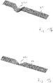
- Fig. 1b shows a substrate 42 on which a road surface 44 (see. Fig. 1c ) should be applied.
- the substrate 42 has a recess 42v, in which more road surface would be involved. For this, however, the regulation must be able to act sufficiently fast.
- the height control is performed at the front of the paver, while the tilt control done at the back. The result after a damped, low-pass filtered control is in Fig. 1c shown.
- the recess 42v has again left a depression in the applied road surface 44v.
- a inclination sensor 10 ' which can be used in the sensor system 100 explained above, is shown.
- the tilt sensor 10 ' is designed here as a servo inclinometer (tension band sensor). It is conceivable to use a combination of several inclination sensors of the same type or else of different design.
- Such a tension band sensor 10 ' is essentially based on a tension band measuring mechanism 12 in combination with a pendulum 14.
- the tension band measuring unit 12 comprises a tension band 2b, a spin coil system 12d and a core 12k.
- the core 12k is suspended within the spool system 12d with the aid of the tension band 12b.
- a pendulum mass 14m is coupled to the core 12k, in which case the pendulum mass projects out of the rotary coil measuring device 12d by means of an arm.
- the core 12k and thus also the pendulum mass 14m tilt with respect to the vertical axis 12b by the inclination angle ⁇ .
- the pendulum mass 14m on the arm can move between two stop stops 14s1 and 14s2. Between these stop stops 14s1 and 14s2, the position of the pendulum mass 14m is determined by means of the position sensor 16.
- This position sensor 16 is coupled to the electronics 18 of the tension band sensor 10 '.
- the electronics 18 comprise an electric module 18e, a servo amplifier 18v and an attenuation network 18d. Furthermore, connections for the DC supply voltage, the output signal and an input for a self-test are provided. As indicated by the dashed line, as a rule all these modules 12, 14, 16 and 18 are located in a common (sealed) housing 19.
- the tension band sensor 10 In the case of the tension band sensor 10 'shown here, it is not the deflection of the pendulum 14m that is measured, but the current required to move the pendulum 14m back to the zero position or to hold it there.
- the measuring signal is proportional to the angle of inclination, which represents the deviation from the predetermined perpendicular direction.
- This tilt signal is then, as already explained above with reference to FIG. 1a, corrected with the rotation rate signal.
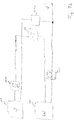
- Fig. 2b illustrates a possible interconnection by means of which inclination sensor and rotation rate sensor can be combined with each other.
- the tilt sensor 10 outputs a signal indicating ⁇
- the rotation rate sensor 20 outputs a signal indicative of the rotation rate ⁇ .
- the slope signal ⁇ is derived by time (see block 11a) and compared to the rotation rate signal w (see block 11v). It can be seen from this comparison 11v whether, starting from a rotation rate w, there is a need to correct the tilt signal ⁇ .
- These corrections are made on the basis of the rotation rate signal w, z. B. integrated over time (see unit 21 i), ie ⁇ ⁇ dt.
- the corrected tilt signal ⁇ ' can be output.
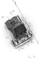
- Fig. 3a shows a paver 80 with an extendable screed 82.
- the extension mechanism of the extendable screed 82 is based on Fig. 3b or 3c to recognize.
- the screed 82 on each side extendable machine parts 84a and 84b.
- the transverse directional (with respect to the direction of travel 80f) aligned plank 82 is extended by the extendable machine parts 84a and 84b, which can lead to a lateral acceleration.
- the rotation rate sensor is arranged together with the tilt sensor in a common housing in which the electronics for the fusion of the two sensor signals can be provided.
- the tilt sensor is according to a preferred embodiment on the cross-beam 80q, which represents a connection between the left and the right arm of the screed 82, arranged.
- the arranged sensor since it is assumed that the inclination sensor and the acceleration sensor combined appear as a sensor system, the arranged sensor has the reference numeral 100 for the sensor system.
- the lateral inclination and rotation of the screed 82 is determined. However, this is directly related to the rotation and transverse inclination of the screed 82, since the screed 82 are connected to the paver 80 by means of tension arms 86a and 86b, the crossbeam 80q being provided between the tension arms 86a and 86b.
- the cross-beam can be rigid or connected by joints with the Zugarmen 86a and 86b. These traction arms are adjustable, so that so the inclination of the screed 82 and the height of the screed 82 can be controlled. In other words, the inclination sensor 100 is mechanically coupled to the screed 82.
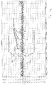
- FIGS. 4a and 4b the effectiveness of the acceleration compensated inclination sensor is shown.
- Fig. 4a and 4b show in each case the sensor data of the tilt sensor and an acceleration-compensated tilt sensor, wherein in Fig. 4b the relevant points are highlighted during the test drive. It should be noted here that the sensor signals are plotted over time, with the temporal dimension being equivalent to the distance covered by the paver.
- the curve 70n represents the measured values of a commercially available inclination sensor (here a tension band sensor), while the curve 70m illustrates an averaging of the measured values 70n which is currently used in order to minimize the disturbing influences.
- the curve 72bn shows the position of a tilt sensor combined with a rotation rate sensor (gyro sensor), that is, the acceleration-compensated tilt signal. As can be seen, this is compared to the tilt signal and the averaged slope signal provided with much less large rashes, for example, resulting from the retraction of the screed against material and from the extension of the screed.
- the peaks in the curve are created by extending or retracting the variable screed.
- the paver consists of a tractor (also called a tractor) and a screed.
- This screed is floating, which means that it is pulled in principle only behind the tractor. It is possible to change the angle of attack of the screed, which leads to a different Aufschwimm .
- When extending the Varioteils of the screed pushes a hydraulic extension of the screed away. In this case, the hydraulics work only against friction.
- the hydraulics must additionally work against the material (asphalt) that lies in front of the screed. Therefore, much larger lateral accelerations are to be expected here.
- the sensor is mounted on the cross-connection between the right and the left arm and is intended to measure the bank of the screed (this position was selected for technical reasons).
- the further embodiments relate to a method that the steps "determining a prevailing at the screed inclination and detection of the at Bohle predominant lateral acceleration "and” calculating an acceleration-compensated tilt signal based on the tilt signal and the yaw rate signal ".
- aspects have been described in the context of a device, it will be understood that these aspects also constitute a description of the corresponding method, so that a block or a component of a device is also to be understood as a corresponding method step or as a feature of a method step. Similarly, aspects described in connection with or as a method step also represent a description of a corresponding block or detail or feature of a corresponding device.
- Some or all of the method steps may be performed by a hardware device (or using a hardware device). Apparatus), such as a microprocessor, a programmable computer or an electronic circuit. For some Embodiments, some or more of the most important method steps may be performed by such an apparatus.
- some embodiments according to the invention include a data carrier having electronically readable control signals capable of interacting with a programmable computer system such that one of the methods described herein is performed.
- a programmable logic device eg, a field programmable gate array, an FPGA
- a field programmable gate array may cooperate with a microprocessor to perform one of the methods described herein.
- the methods are performed by any hardware device. This may be a universal hardware such as a computer processor (CPU) or hardware specific to the process, such as an ASIC.
Landscapes
- Engineering & Computer Science (AREA)
- Physics & Mathematics (AREA)
- General Physics & Mathematics (AREA)
- Radar, Positioning & Navigation (AREA)
- Remote Sensing (AREA)
- Architecture (AREA)
- Civil Engineering (AREA)
- Structural Engineering (AREA)
- Road Paving Machines (AREA)
Priority Applications (1)
| Application Number | Priority Date | Filing Date | Title |
|---|---|---|---|
| EP16181628.5A EP3276080B1 (fr) | 2016-07-28 | 2016-07-28 | Système de capteurs pour une finisseuse de route |
Applications Claiming Priority (1)
| Application Number | Priority Date | Filing Date | Title |
|---|---|---|---|
| EP16181628.5A EP3276080B1 (fr) | 2016-07-28 | 2016-07-28 | Système de capteurs pour une finisseuse de route |
Publications (2)
| Publication Number | Publication Date |
|---|---|
| EP3276080A1 true EP3276080A1 (fr) | 2018-01-31 |
| EP3276080B1 EP3276080B1 (fr) | 2019-12-04 |
Family
ID=56567428
Family Applications (1)
| Application Number | Title | Priority Date | Filing Date |
|---|---|---|---|
| EP16181628.5A Active EP3276080B1 (fr) | 2016-07-28 | 2016-07-28 | Système de capteurs pour une finisseuse de route |
Country Status (1)
| Country | Link |
|---|---|
| EP (1) | EP3276080B1 (fr) |
Cited By (3)
| Publication number | Priority date | Publication date | Assignee | Title |
|---|---|---|---|---|
| CN110318325A (zh) * | 2018-03-30 | 2019-10-11 | 卡特彼勒天宝控制技术有限责任公司 | 用于施工机械的延伸器移动的等级和斜率锁定 |
| CN112012083A (zh) * | 2019-05-28 | 2020-12-01 | 卡特彼勒路面机械公司 | 用于定位整平器板的方法和系统 |
| US12078997B2 (en) | 2021-09-08 | 2024-09-03 | Caterpillar Paving Products Inc. | Optimum screed angle of attack setting and automatic adjustment |
Citations (4)
| Publication number | Priority date | Publication date | Assignee | Title |
|---|---|---|---|---|
| US5044820A (en) * | 1989-03-23 | 1991-09-03 | Abg-Werke Gmbh | Road-finishing apparatus with improved control over laying beam |
| US20110085859A1 (en) * | 2009-10-08 | 2011-04-14 | Jerald Wayne Yost | Gyro compensated inclinometer for cross slope control of concrete screed |
| US20130080112A1 (en) * | 2011-09-28 | 2013-03-28 | Caterpillar Inc. | Inclination angle compensation systems and methods |
| DE102014014384A1 (de) | 2014-10-02 | 2016-04-07 | Dynapac Gmbh | Straßenfertiger und Verfahren zur Herstellung eines Straßenbelags |
-
2016
- 2016-07-28 EP EP16181628.5A patent/EP3276080B1/fr active Active
Patent Citations (4)
| Publication number | Priority date | Publication date | Assignee | Title |
|---|---|---|---|---|
| US5044820A (en) * | 1989-03-23 | 1991-09-03 | Abg-Werke Gmbh | Road-finishing apparatus with improved control over laying beam |
| US20110085859A1 (en) * | 2009-10-08 | 2011-04-14 | Jerald Wayne Yost | Gyro compensated inclinometer for cross slope control of concrete screed |
| US20130080112A1 (en) * | 2011-09-28 | 2013-03-28 | Caterpillar Inc. | Inclination angle compensation systems and methods |
| DE102014014384A1 (de) | 2014-10-02 | 2016-04-07 | Dynapac Gmbh | Straßenfertiger und Verfahren zur Herstellung eines Straßenbelags |
Cited By (4)
| Publication number | Priority date | Publication date | Assignee | Title |
|---|---|---|---|---|
| CN110318325A (zh) * | 2018-03-30 | 2019-10-11 | 卡特彼勒天宝控制技术有限责任公司 | 用于施工机械的延伸器移动的等级和斜率锁定 |
| CN112012083A (zh) * | 2019-05-28 | 2020-12-01 | 卡特彼勒路面机械公司 | 用于定位整平器板的方法和系统 |
| CN112012083B (zh) * | 2019-05-28 | 2023-08-15 | 卡特彼勒路面机械公司 | 用于定位整平器板的方法和系统 |
| US12078997B2 (en) | 2021-09-08 | 2024-09-03 | Caterpillar Paving Products Inc. | Optimum screed angle of attack setting and automatic adjustment |
Also Published As
| Publication number | Publication date |
|---|---|
| EP3276080B1 (fr) | 2019-12-04 |
Similar Documents
| Publication | Publication Date | Title |
|---|---|---|
| EP3462855B1 (fr) | Système de régulation et/ou de commande, machine agricole comprenant un tel système et procédé permettant de faire fonctionner une machine agricole | |
| EP3065530B1 (fr) | Dispositif pour distribuer des substances actives liquides et/ou solides et procédé de commande d'un tel dispositif | |
| EP3007553B1 (fr) | Dispositif de distribution de substances actives liquides et/ou solides et procédé de commande d'un tel dispositif | |
| EP3035795B1 (fr) | Pulvérisateur pour épandre des substances actives liquides et/ou solides et contrôle d'un tel | |
| EP2921588B1 (fr) | Finisseuse de route dotée d'un dispositif de détection de l'épaisseur de couche et procédé de détection de l'épaisseur d'une couche de matériau déposée | |
| EP3259221B1 (fr) | Contrôle de la position d'une pointe de mât | |
| EP2591657B1 (fr) | Dispositif mobile destiné à sortir des agents actifs liquides et/ou solides et procédé de commande du dispositif | |
| EP3064061A1 (fr) | Dispositif d'extraction de liquides et/ou d'agents actifs solides et procede de commande d'un tel dispositif | |
| DE112015006905T5 (de) | Kalibriervorrichtung einer Arbeitsmaschine, Arbeitsmaschine und Kalibrierverfahren einer Arbeitsmaschine | |
| EP2422018A1 (fr) | Engin de chantier mobile équipé d'un dispositif de régulation de position d'un bras de travail et procédé pour réguler la position d'un bras de travail d'un engin de chantier mobile | |
| EP3159191B1 (fr) | Système destiné à influencer l'alignement d'un véhicule | |
| EP4224112A2 (fr) | Système de mesure et contrôleur | |
| EP3276080B1 (fr) | Système de capteurs pour une finisseuse de route | |
| DE102005038390B4 (de) | Lenkung eines Fahrzeugs | |
| EP2936980A1 (fr) | Pulvérisateur à cultures | |
| DE29918747U1 (de) | Vorrichtung zum Steuern eines Straßenfertigers | |
| DE19951296A1 (de) | Vorrichtung und Verfahren zum Steuern eines Strassenfertigers | |
| WO2018162539A1 (fr) | Dispositif de régulation, véhicule utilitaire agricole et procédé de régulation d'un véhicule utilitaire agricole | |
| DE1944713C3 (de) | Planierraupe | |
| DE102025125159A1 (de) | System und verfahren für ein betreiben von wahrnehmungsvorrichtungen in mobilen maschinen | |
| DE9309060U1 (de) | Planiergerät |
Legal Events
| Date | Code | Title | Description |
|---|---|---|---|
| PUAI | Public reference made under article 153(3) epc to a published international application that has entered the european phase |
Free format text: ORIGINAL CODE: 0009012 |
|
| STAA | Information on the status of an ep patent application or granted ep patent |
Free format text: STATUS: THE APPLICATION HAS BEEN PUBLISHED |
|
| AK | Designated contracting states |
Kind code of ref document: A1 Designated state(s): AL AT BE BG CH CY CZ DE DK EE ES FI FR GB GR HR HU IE IS IT LI LT LU LV MC MK MT NL NO PL PT RO RS SE SI SK SM TR |
|
| AX | Request for extension of the european patent |
Extension state: BA ME |
|
| STAA | Information on the status of an ep patent application or granted ep patent |
Free format text: STATUS: REQUEST FOR EXAMINATION WAS MADE |
|
| 17P | Request for examination filed |
Effective date: 20180627 |
|
| RBV | Designated contracting states (corrected) |
Designated state(s): AL AT BE BG CH CY CZ DE DK EE ES FI FR GB GR HR HU IE IS IT LI LT LU LV MC MK MT NL NO PL PT RO RS SE SI SK SM TR |
|
| GRAP | Despatch of communication of intention to grant a patent |
Free format text: ORIGINAL CODE: EPIDOSNIGR1 |
|
| STAA | Information on the status of an ep patent application or granted ep patent |
Free format text: STATUS: GRANT OF PATENT IS INTENDED |
|
| RIC1 | Information provided on ipc code assigned before grant |
Ipc: G01C 9/08 20060101AFI20190528BHEP |
|
| RIC1 | Information provided on ipc code assigned before grant |
Ipc: E01C 19/48 20060101AFI20190531BHEP Ipc: G01C 9/08 20060101ALI20190531BHEP |
|
| INTG | Intention to grant announced |
Effective date: 20190619 |
|
| GRAS | Grant fee paid |
Free format text: ORIGINAL CODE: EPIDOSNIGR3 |
|
| GRAA | (expected) grant |
Free format text: ORIGINAL CODE: 0009210 |
|
| STAA | Information on the status of an ep patent application or granted ep patent |
Free format text: STATUS: THE PATENT HAS BEEN GRANTED |
|
| AK | Designated contracting states |
Kind code of ref document: B1 Designated state(s): AL AT BE BG CH CY CZ DE DK EE ES FI FR GB GR HR HU IE IS IT LI LT LU LV MC MK MT NL NO PL PT RO RS SE SI SK SM TR |
|
| REG | Reference to a national code |
Ref country code: GB Ref legal event code: FG4D Free format text: NOT ENGLISH |
|
| REG | Reference to a national code |
Ref country code: CH Ref legal event code: EP |
|
| REG | Reference to a national code |
Ref country code: AT Ref legal event code: REF Ref document number: 1209542 Country of ref document: AT Kind code of ref document: T Effective date: 20191215 |
|
| REG | Reference to a national code |
Ref country code: DE Ref legal event code: R096 Ref document number: 502016007835 Country of ref document: DE |
|
| REG | Reference to a national code |
Ref country code: IE Ref legal event code: FG4D Free format text: LANGUAGE OF EP DOCUMENT: GERMAN |
|
| REG | Reference to a national code |
Ref country code: NL Ref legal event code: MP Effective date: 20191204 |
|
| REG | Reference to a national code |
Ref country code: LT Ref legal event code: MG4D |
|
| PG25 | Lapsed in a contracting state [announced via postgrant information from national office to epo] |
Ref country code: FI Free format text: LAPSE BECAUSE OF FAILURE TO SUBMIT A TRANSLATION OF THE DESCRIPTION OR TO PAY THE FEE WITHIN THE PRESCRIBED TIME-LIMIT Effective date: 20191204 Ref country code: BG Free format text: LAPSE BECAUSE OF FAILURE TO SUBMIT A TRANSLATION OF THE DESCRIPTION OR TO PAY THE FEE WITHIN THE PRESCRIBED TIME-LIMIT Effective date: 20200304 Ref country code: NO Free format text: LAPSE BECAUSE OF FAILURE TO SUBMIT A TRANSLATION OF THE DESCRIPTION OR TO PAY THE FEE WITHIN THE PRESCRIBED TIME-LIMIT Effective date: 20200304 Ref country code: GR Free format text: LAPSE BECAUSE OF FAILURE TO SUBMIT A TRANSLATION OF THE DESCRIPTION OR TO PAY THE FEE WITHIN THE PRESCRIBED TIME-LIMIT Effective date: 20200305 Ref country code: SE Free format text: LAPSE BECAUSE OF FAILURE TO SUBMIT A TRANSLATION OF THE DESCRIPTION OR TO PAY THE FEE WITHIN THE PRESCRIBED TIME-LIMIT Effective date: 20191204 Ref country code: LV Free format text: LAPSE BECAUSE OF FAILURE TO SUBMIT A TRANSLATION OF THE DESCRIPTION OR TO PAY THE FEE WITHIN THE PRESCRIBED TIME-LIMIT Effective date: 20191204 Ref country code: LT Free format text: LAPSE BECAUSE OF FAILURE TO SUBMIT A TRANSLATION OF THE DESCRIPTION OR TO PAY THE FEE WITHIN THE PRESCRIBED TIME-LIMIT Effective date: 20191204 |
|
| PG25 | Lapsed in a contracting state [announced via postgrant information from national office to epo] |
Ref country code: RS Free format text: LAPSE BECAUSE OF FAILURE TO SUBMIT A TRANSLATION OF THE DESCRIPTION OR TO PAY THE FEE WITHIN THE PRESCRIBED TIME-LIMIT Effective date: 20191204 Ref country code: HR Free format text: LAPSE BECAUSE OF FAILURE TO SUBMIT A TRANSLATION OF THE DESCRIPTION OR TO PAY THE FEE WITHIN THE PRESCRIBED TIME-LIMIT Effective date: 20191204 |
|
| PG25 | Lapsed in a contracting state [announced via postgrant information from national office to epo] |
Ref country code: AL Free format text: LAPSE BECAUSE OF FAILURE TO SUBMIT A TRANSLATION OF THE DESCRIPTION OR TO PAY THE FEE WITHIN THE PRESCRIBED TIME-LIMIT Effective date: 20191204 |
|
| PG25 | Lapsed in a contracting state [announced via postgrant information from national office to epo] |
Ref country code: NL Free format text: LAPSE BECAUSE OF FAILURE TO SUBMIT A TRANSLATION OF THE DESCRIPTION OR TO PAY THE FEE WITHIN THE PRESCRIBED TIME-LIMIT Effective date: 20191204 Ref country code: EE Free format text: LAPSE BECAUSE OF FAILURE TO SUBMIT A TRANSLATION OF THE DESCRIPTION OR TO PAY THE FEE WITHIN THE PRESCRIBED TIME-LIMIT Effective date: 20191204 Ref country code: PT Free format text: LAPSE BECAUSE OF FAILURE TO SUBMIT A TRANSLATION OF THE DESCRIPTION OR TO PAY THE FEE WITHIN THE PRESCRIBED TIME-LIMIT Effective date: 20200429 Ref country code: CZ Free format text: LAPSE BECAUSE OF FAILURE TO SUBMIT A TRANSLATION OF THE DESCRIPTION OR TO PAY THE FEE WITHIN THE PRESCRIBED TIME-LIMIT Effective date: 20191204 Ref country code: RO Free format text: LAPSE BECAUSE OF FAILURE TO SUBMIT A TRANSLATION OF THE DESCRIPTION OR TO PAY THE FEE WITHIN THE PRESCRIBED TIME-LIMIT Effective date: 20191204 Ref country code: ES Free format text: LAPSE BECAUSE OF FAILURE TO SUBMIT A TRANSLATION OF THE DESCRIPTION OR TO PAY THE FEE WITHIN THE PRESCRIBED TIME-LIMIT Effective date: 20191204 |
|
| PG25 | Lapsed in a contracting state [announced via postgrant information from national office to epo] |
Ref country code: SM Free format text: LAPSE BECAUSE OF FAILURE TO SUBMIT A TRANSLATION OF THE DESCRIPTION OR TO PAY THE FEE WITHIN THE PRESCRIBED TIME-LIMIT Effective date: 20191204 Ref country code: IS Free format text: LAPSE BECAUSE OF FAILURE TO SUBMIT A TRANSLATION OF THE DESCRIPTION OR TO PAY THE FEE WITHIN THE PRESCRIBED TIME-LIMIT Effective date: 20200404 Ref country code: SK Free format text: LAPSE BECAUSE OF FAILURE TO SUBMIT A TRANSLATION OF THE DESCRIPTION OR TO PAY THE FEE WITHIN THE PRESCRIBED TIME-LIMIT Effective date: 20191204 |
|
| REG | Reference to a national code |
Ref country code: DE Ref legal event code: R097 Ref document number: 502016007835 Country of ref document: DE |
|
| PLBE | No opposition filed within time limit |
Free format text: ORIGINAL CODE: 0009261 |
|
| STAA | Information on the status of an ep patent application or granted ep patent |
Free format text: STATUS: NO OPPOSITION FILED WITHIN TIME LIMIT |
|
| PG25 | Lapsed in a contracting state [announced via postgrant information from national office to epo] |
Ref country code: DK Free format text: LAPSE BECAUSE OF FAILURE TO SUBMIT A TRANSLATION OF THE DESCRIPTION OR TO PAY THE FEE WITHIN THE PRESCRIBED TIME-LIMIT Effective date: 20191204 |
|
| 26N | No opposition filed |
Effective date: 20200907 |
|
| PG25 | Lapsed in a contracting state [announced via postgrant information from national office to epo] |
Ref country code: PL Free format text: LAPSE BECAUSE OF FAILURE TO SUBMIT A TRANSLATION OF THE DESCRIPTION OR TO PAY THE FEE WITHIN THE PRESCRIBED TIME-LIMIT Effective date: 20191204 Ref country code: SI Free format text: LAPSE BECAUSE OF FAILURE TO SUBMIT A TRANSLATION OF THE DESCRIPTION OR TO PAY THE FEE WITHIN THE PRESCRIBED TIME-LIMIT Effective date: 20191204 |
|
| PG25 | Lapsed in a contracting state [announced via postgrant information from national office to epo] |
Ref country code: IT Free format text: LAPSE BECAUSE OF FAILURE TO SUBMIT A TRANSLATION OF THE DESCRIPTION OR TO PAY THE FEE WITHIN THE PRESCRIBED TIME-LIMIT Effective date: 20191204 |
|
| PG25 | Lapsed in a contracting state [announced via postgrant information from national office to epo] |
Ref country code: MC Free format text: LAPSE BECAUSE OF FAILURE TO SUBMIT A TRANSLATION OF THE DESCRIPTION OR TO PAY THE FEE WITHIN THE PRESCRIBED TIME-LIMIT Effective date: 20191204 |
|
| REG | Reference to a national code |
Ref country code: CH Ref legal event code: PL |
|
| REG | Reference to a national code |
Ref country code: BE Ref legal event code: MM Effective date: 20200731 |
|
| PG25 | Lapsed in a contracting state [announced via postgrant information from national office to epo] |
Ref country code: CH Free format text: LAPSE BECAUSE OF NON-PAYMENT OF DUE FEES Effective date: 20200731 Ref country code: LI Free format text: LAPSE BECAUSE OF NON-PAYMENT OF DUE FEES Effective date: 20200731 Ref country code: LU Free format text: LAPSE BECAUSE OF NON-PAYMENT OF DUE FEES Effective date: 20200728 |
|
| PG25 | Lapsed in a contracting state [announced via postgrant information from national office to epo] |
Ref country code: BE Free format text: LAPSE BECAUSE OF NON-PAYMENT OF DUE FEES Effective date: 20200731 |
|
| PG25 | Lapsed in a contracting state [announced via postgrant information from national office to epo] |
Ref country code: IE Free format text: LAPSE BECAUSE OF NON-PAYMENT OF DUE FEES Effective date: 20200728 |
|
| PG25 | Lapsed in a contracting state [announced via postgrant information from national office to epo] |
Ref country code: TR Free format text: LAPSE BECAUSE OF FAILURE TO SUBMIT A TRANSLATION OF THE DESCRIPTION OR TO PAY THE FEE WITHIN THE PRESCRIBED TIME-LIMIT Effective date: 20191204 Ref country code: MT Free format text: LAPSE BECAUSE OF FAILURE TO SUBMIT A TRANSLATION OF THE DESCRIPTION OR TO PAY THE FEE WITHIN THE PRESCRIBED TIME-LIMIT Effective date: 20191204 Ref country code: CY Free format text: LAPSE BECAUSE OF FAILURE TO SUBMIT A TRANSLATION OF THE DESCRIPTION OR TO PAY THE FEE WITHIN THE PRESCRIBED TIME-LIMIT Effective date: 20191204 |
|
| PG25 | Lapsed in a contracting state [announced via postgrant information from national office to epo] |
Ref country code: MK Free format text: LAPSE BECAUSE OF FAILURE TO SUBMIT A TRANSLATION OF THE DESCRIPTION OR TO PAY THE FEE WITHIN THE PRESCRIBED TIME-LIMIT Effective date: 20191204 |
|
| REG | Reference to a national code |
Ref country code: AT Ref legal event code: MM01 Ref document number: 1209542 Country of ref document: AT Kind code of ref document: T Effective date: 20210728 |
|
| PG25 | Lapsed in a contracting state [announced via postgrant information from national office to epo] |
Ref country code: AT Free format text: LAPSE BECAUSE OF NON-PAYMENT OF DUE FEES Effective date: 20210728 |
|
| P01 | Opt-out of the competence of the unified patent court (upc) registered |
Effective date: 20230523 |
|
| PGFP | Annual fee paid to national office [announced via postgrant information from national office to epo] |
Ref country code: DE Payment date: 20250619 Year of fee payment: 10 |
|
| PGFP | Annual fee paid to national office [announced via postgrant information from national office to epo] |
Ref country code: GB Payment date: 20250725 Year of fee payment: 10 |
|
| PGFP | Annual fee paid to national office [announced via postgrant information from national office to epo] |
Ref country code: FR Payment date: 20250729 Year of fee payment: 10 |