EP3276244B1 - Gabarit pour installer des robinets à pression - Google Patents
Gabarit pour installer des robinets à pression Download PDFInfo
- Publication number
- EP3276244B1 EP3276244B1 EP16897048.1A EP16897048A EP3276244B1 EP 3276244 B1 EP3276244 B1 EP 3276244B1 EP 16897048 A EP16897048 A EP 16897048A EP 3276244 B1 EP3276244 B1 EP 3276244B1
- Authority
- EP
- European Patent Office
- Prior art keywords
- diameter enlarging
- diameter
- roller
- snap tap
- metal sleeve
- Prior art date
- Legal status (The legal status is an assumption and is not a legal conclusion. Google has not performed a legal analysis and makes no representation as to the accuracy of the status listed.)
- Not-in-force
Links
Images


Classifications
-
- F—MECHANICAL ENGINEERING; LIGHTING; HEATING; WEAPONS; BLASTING
- F16—ENGINEERING ELEMENTS AND UNITS; GENERAL MEASURES FOR PRODUCING AND MAINTAINING EFFECTIVE FUNCTIONING OF MACHINES OR INSTALLATIONS; THERMAL INSULATION IN GENERAL
- F16L—PIPES; JOINTS OR FITTINGS FOR PIPES; SUPPORTS FOR PIPES, CABLES OR PROTECTIVE TUBING; MEANS FOR THERMAL INSULATION IN GENERAL
- F16L41/00—Branching pipes; Joining pipes to walls
- F16L41/04—Tapping pipe walls, i.e. making connections through the walls of pipes while they are carrying fluids; Fittings therefor
- F16L41/06—Tapping pipe walls, i.e. making connections through the walls of pipes while they are carrying fluids; Fittings therefor making use of attaching means embracing the pipe
-
- E—FIXED CONSTRUCTIONS
- E03—WATER SUPPLY; SEWERAGE
- E03B—INSTALLATIONS OR METHODS FOR OBTAINING, COLLECTING, OR DISTRIBUTING WATER
- E03B7/00—Water main or service pipe systems
- E03B7/02—Public or like main pipe systems
-
- F—MECHANICAL ENGINEERING; LIGHTING; HEATING; WEAPONS; BLASTING
- F16—ENGINEERING ELEMENTS AND UNITS; GENERAL MEASURES FOR PRODUCING AND MAINTAINING EFFECTIVE FUNCTIONING OF MACHINES OR INSTALLATIONS; THERMAL INSULATION IN GENERAL
- F16L—PIPES; JOINTS OR FITTINGS FOR PIPES; SUPPORTS FOR PIPES, CABLES OR PROTECTIVE TUBING; MEANS FOR THERMAL INSULATION IN GENERAL
- F16L41/00—Branching pipes; Joining pipes to walls
- F16L41/08—Joining pipes to walls or pipes, the joined pipe axis being perpendicular to the plane of a wall or to the axis of another pipe
- F16L41/082—Non-disconnectable joints, e.g. soldered, adhesive or caulked joints
-
- F—MECHANICAL ENGINEERING; LIGHTING; HEATING; WEAPONS; BLASTING
- F16—ENGINEERING ELEMENTS AND UNITS; GENERAL MEASURES FOR PRODUCING AND MAINTAINING EFFECTIVE FUNCTIONING OF MACHINES OR INSTALLATIONS; THERMAL INSULATION IN GENERAL
- F16L—PIPES; JOINTS OR FITTINGS FOR PIPES; SUPPORTS FOR PIPES, CABLES OR PROTECTIVE TUBING; MEANS FOR THERMAL INSULATION IN GENERAL
- F16L41/00—Branching pipes; Joining pipes to walls
- F16L41/08—Joining pipes to walls or pipes, the joined pipe axis being perpendicular to the plane of a wall or to the axis of another pipe
- F16L41/088—Joining pipes to walls or pipes, the joined pipe axis being perpendicular to the plane of a wall or to the axis of another pipe fixed using an elastic grommet between the extremity of the tube and the wall
-
- E—FIXED CONSTRUCTIONS
- E03—WATER SUPPLY; SEWERAGE
- E03B—INSTALLATIONS OR METHODS FOR OBTAINING, COLLECTING, OR DISTRIBUTING WATER
- E03B9/00—Methods or installations for drawing-off water
- E03B9/02—Hydrants; Arrangements of valves therein; Keys for hydrants
- E03B9/08—Underground hydrants
- E03B9/12—Stand-pipes
Definitions
- the present invention relates to a technique concerning a snap tap mounting jig for mounting a snap tap in a water diverting port formed by drilling a peripheral wall of a water pipe.
- a water diverting port is formed by drilling a peripheral wall of the water pipe with a drilling machine equipped with a drill, and a metal sleeve or a snap tap integrally formed with such a metal sleeve is mounted on a periphery of the water diverting port together with a rubber packing so that water can be taken out from the water pipe in a diverting manner while preventing leakage of water from the water diverting port.
- metal sleeve a metal sleeve or a sleeve portion which is integrally formed with a snap tap (hereinafter also simply referred to as "metal sleeve") to a water diverting port
- metal sleeve a metal sleeve or a sleeve portion which is integrally formed with a snap tap
- a method where an opening portion formed at one end of the metal sleeve is made to project from the inside of the water diverting port of the water pipe, and a distal end portion of the opening of the metal sleeve which projects into the inside of the water pipe is bent by a diameter enlarging head mounted on a distal end of a main shaft of a jig inserted into the inside of the metal sleeve, a diameter enlarging roller mounted on the diameter enlarging head obliquely and the like such that the distal end portion of the opening of the metal sleeve is folded back on
- the snap tap mounting jig which is, as described above, constituted of the diameter enlarging head mounted on the distal end of the main shaft and the diameter enlarging roller mounted on the diameter enlarging head or the like obliquely.
- the diameter enlarging roller having a Japanese-hand-drum shape and mounted on the diameter enlarging head formed on the distal end of the main shaft obliquely is brought into contact with the peripheral edge portion of the opening of the metal sleeve while manually adjusting the elevation or lowering of the main shaft and, subsequently, the peripheral edge portion of the opening of the metal sleeve is bent by the diameter enlarging roller arranged on the distal end of the main shaft such that the peripheral edge portion is folded back to the outside by rotating the main shaft and, thereafter, the peripheral portion of the opening of the metal sleeve is engaged by caulking to the peripheral edge of the water diverting port formed by drilling in the peripheral wall of the water pipe thus making the snap tap engaged and fixed to the water diverting port and performing sealing of the water diverting port with certainty.
- the structure is adopted where the metal part is caulked to the water diverting port of the water pipe. Accordingly, when a pipe wall thickness of the water pipe differs or a size of the water diverting port differs, it is necessary to communicably connect the snap tap to the water diverting port with certainty in a state where a complete sealing function is acquired corresponding to a change in such a situation. To this end, it is necessary to bend and caulk a diameter-enlarged end edge portion of the metal sleeve to the water diverting port of the water pipe with certainty.
- Patent Literature 1 WIPO 2014/148645 brochure
- the end edge flange of the roller is deformed outward so that an inner surface of a roller accommodating chamber formed on the diameter enlarging head and the end edge flange come into contact with each other whereby the roller is brought into a non-rotatable state.
- the present invention has been made in view of such circumstances, and it is an object of the present invention to provide a snap tap mounting jig for mounting a snap tap where the generation of buckling can be prevented by reducing a diameter enlarging pressing force of a diameter enlarging roller, a shim can be mounted on both end surfaces of the diameter enlarging roller with certainty, and a fold-back deformation amount of a metal sleeve can be checked from the outside.
- the recessed portion of the diameter enlarging roller is formed such that a substantially upper half portion of the recessed portion is formed into a tapered shape, and a substantially lower half portion of the recessed portion is formed into a rounded shape.
- a diameter enlarging force applied to the terminal flange portion is increased as an angle of the diameter enlarging roller shaft is increased, while the diameter enlarging force is decreased as the angle of the diameter enlarging roller shaft is decreased. Accordingly, the angle can be adjusted corresponding to a required diameter enlarging force.
- the distal end of the opening of the metal sleeve is elastically deformed by applying a force by the tapered portion immediately before the distal end of the opening of the metal sleeve is plastically deformed, and the distal end of the opening of the metal sleeve is folded back while being plastically deformed by applying final diameter enlargement to the metal sleeve by the rounded portion of the diameter enlarging roller in such a state and hence, a pressure applied to a roller accommodating chamber and an outer periphery of the roller shaft is reduced. Accordingly, the snap tap mounting jig is also applicable to an operation which requires a large diameter enlarging force such as a diverting operation where a water pipe having a large diverting diameter and a large pipe thickness is used.
- a diameter enlarging force can be decreased by adjusting an inclination angle of the tapered portion of the diameter enlarging roller within a range of an angle of depression from 65 degrees to 77 degrees with respect to an imaginary straight line orthogonal to an axis of the eccentric movable shaft, and a pressure of the roller applied to an inner wall of the roller accommodating chamber can be adjusted by changing an angle of the roller with respect to the shaft.
- a force applied to a terminal end flange portion of the diameter enlarging roller can be increased by increasing the inclination of the roller shaft, while a force applied to the terminal end flange portion of the diameter enlarging roller can be decreased by decreasing the inclination of the roller shaft.
- the diameter enlarging force generated by the tapered portion of the diameter enlarging roller applies a deformation stress to the lower end portion of the metal sleeve along the roller shaft, the diameter enlarging force does not become a large force which generates plastic deformation such as the rounded portion and hence, the plastic deformation at the rounded portion in the next step can be performed in a rounded shape with certainty and accuracy.
- a diameter enlarging stress at the tapered portion pushes the diameter enlarging roller in a start end flange portion direction
- a diameter enlarging stress at the rounded portion pushes the diameter enlarging roller in the terminal end flange portion direction. Accordingly, a value obtained by subtracting an elastic deformation force generated by the tapered portion from a plastic deformation force generated by the rounded portion of the diameter enlarging roller becomes a pressure applied to the inner wall of the roller accommodating chamber and hence, an applied pressure load can be decreased.
- a diameter enlarging operation can be performed with a small force and hence, wear of the shim or the like is decreased whereby the deformation of the start end flange portion and the terminal end flange portion of the diameter enlarging portion is also obviated.
- the diameter enlarging roller has a start end flange portion with which the distal end of the metal sleeve is brought into contact at the time of starting the enlarging of a diameter of the metal sleeve on the upper end side of the recessed portion, and a friction portion may be formed on the start end flange portion.
- a rotational force of the diameter enlarging handle can be efficiently transmitted to the diameter enlarging roller and hence, a force in a pull-up direction applied to the diameter enlarging roller can be decreased and hence, lifetimes of members around the diameter enlarging roller can be prolonged by decreasing wears or the like on these members.
- the diameter enlarging roller cannot be rotated due to seizure, the diameter enlargement cannot be performed unless a large force is applied to the diameter enlarging handle.
- seizure of the diameter enlarging roller can be eliminated and hence, it is possible to reduce a force applied to the diameter enlarging handle.
- a groove mark disappears along with the enlargement of diameter of the sleeve and hence, an inner peripheral surface of the sleeve enlarged in a funnel shape can have a smooth surface state.
- the snap tap mounting jig is also applicable to enlarging a diameter of a snap tap.
- the shape of the diameter enlarging roller can be made compact and hence, the diameter enlarging head can be made compact.
- the friction portion is formed by forming friction structural members which generate a frictional force on the circumference of the start end edge portion at predetermined intervals.
- the friction structural members are formed ranging from the start end flange portion to the upper region of the tapered portion, and a groove depth of the crest and valley structure of the friction portion formed of the friction structural members is gradually decreased from the start end flange portion to the tapered portion.
- Peaks of crest portions of the crest and valley structure are obtuse peaks.
- a recessed groove is formed on a start end surface and a terminal end surface of the diameter enlarging roller, and a shim is fitted into the recessed groove.
- the enlarged diameter amount detection mechanism is mounted on the proximal end operating portion of the roller shaft having the distal end on which the diameter enlarging roller is continuously formed, and the enlarged diameter amount detection mechanism is configured to indicate an elevation and a rotational amount of the roller shaft as an enlarged diameter amount by means of a scale marked on the enlarged diameter amount detection nut integrally formed with the roller shaft.
- a pull-up nut for pulling up the roller shaft is threadedly engaged with an upper end portion of the roller shaft, and the enlarged diameter amount detection nut is fitted into an upper portion of the pull-up nut such that the scale portion of the enlarged diameter amount detection nut is fitted on the pull-up nut.
- the scale of the enlarged diameter amount detection nut is exposed from the inside of the pull-up nut corresponding to an elevation amount of the scale, that is, a fold-back amount or a diameter increasing amount of the sleeve, and the fold-back amount or the diameter increasing amount can be detected by reading the scale.
- the enlarged diameter amount of the sleeve can be checked accurately.
- the friction portion is formed on the roller, a slippage of the roller can be prevented and hence, the enlarged diameter amount can be measured with high accuracy.
- the present invention relates to, in a branching work performed without suspending the supply of water, a technique for forming a water diverting port in an outer peripheral wall of the water pipe by drilling and for communicably connecting a snap tap to the water diverting port.
- the present invention is directed to, for example, a snap tap mounting jig where a regeneration pipe is fitted on a deteriorated existing pipe thus forming a water pipe having a duplex pipe structure, a gate valve is fixedly attached to a peripheral wall of the water pipe in a communicable state, a water diverting port is formed by drilling the peripheral wall of the water pipe having a duplex pipe structure using a drill body of a drilling machine which advances and retracts in the inside of a water flow sleeve of the gate valve, the snap tap is mounted on the water diverting port by way of the gate valve without suspending the supply of water and, thereafter, the gate valve is removed and the water diverting port is completely sealed so that the snap tap is communicably connected to the water diverting port.
- sealing of the water diverting port by rubber packing can be performed accurately without requiring an unnecessary diameter enlarging force by devising a shape or an inclination angle of the diameter enlarging roller used in a communicable connection operation of the snap tap.
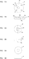
- Fig. 1 is an explanatory view showing a cross section of a water pipe 11 in a state where a gate valve 10 is mounted on the water pipe 11.
- the gate valve 10 is fixedly mounted on the water pipe 11 as shown in Fig. 1 .
- the gate valve 10 is provided for preventing a large amount of water from flowing out from the water pipe 11 during the installation work.
- the gate valve 10 in a case where a hole is formed in a peripheral wall of the water pipe 11 by advancing and retracting a drill portion 14b of a drilling machine 14 (see Fig. 2 ) in the inside of a jig insertion passage 10a of the gate valve 10 or in a case where a snap tap is communicably connected to a water diverting port by a snap tap mounting jig A according to the present invention (see Fig. 7 ), the presence or the non-presence of water flowing from the water diverting port can be controlled by opening or closing the gate valve 10 and hence, the installation work of a snap tap can be realized without suspending the supply of water.
- the gate valve 10 is mounted on the water pipe 11 by fastening a gate valve body 10b onto the water pipe 11 using a chain 10c, a wire or the like.
- a jig passing passage 10a is formed in a center portion of the gate valve body 10b, and the jig passing passage 10a is disposed at a position where a water diverting port is formed in a drilling processing step described later.
- a terminal end of the jig passing passage 10a is stationarily disposed on the peripheral wall of the water pipe 11 by way of a leg sleeve 10d in a watertight manner.
- a shutter 10f which opens or closes the jig passing passage 10a is mounted in a platform 10e of the gate valve body 10b in an advanceable and retractable manner.
- a base portion of the shutter 10f is configured to be operable in an advanceable and retractable manner by an opening/closing handle 10g by way of an advanceable and retractable screw portion 10h.
- a jig connecting flange 10i for mounting and fixing the snap tab mounting jig A according to the present invention is mounted on an upper portion of the gate valve body 10b.
- the gate valve 10 having the above-mentioned structure is mounted and fixed to the water pipe 11, and a lower end flange 14a of the drilling machine 14 is connected and fixed to the jig connecting flange 10i formed on an upper portion of the gate valve 10 thus completing the preparation for an operation of forming a hole in the peripheral wall of the water pipe 11 by drilling (see Fig. 2 ).
- Fig. 2 is an explanatory view for explaining a state where the drilling machine 14 is mounted on the gate valve 10.
- the drilling machine 14 is shown in a state where an upper mechanism of the drilling machine 14 is omitted.
- a drill shaft 14a of the drilling machine 14 is inserted into a jig insertion passage 10a of the gate valve 10, a drill portion 14b mounted on a distal end of the drill shaft 14a is brought into contact with a water diverting port forming position on the peripheral wall of the water pipe 11, and the water diverting port 15 is formed by drilling by a core drill 14c and a center drill 14d provided to the drill portion 14b.
- the shutter 10f of the gate valve 10 is opened, and the center drill 14d and the core drill 14c are advanced into the inside of the jig insertion passage 10a.
- the drill shaft 14a is advanced until a distal end of the center drill 14d penetrates a pipe wall of the water pipe 11 and, subsequently, while flowing out chips generated by cutting by overflowing water through a water drain port not shown in the drawing which is formed in the gate valve 10 additionally, a cutting edge of the core drill 14c is brought into contact with the pipe wall thus forming a circular hole by drilling as the water diverting port 15.
- the drill shaft 14a is elevated so as to remove the drill portion 14b together with the cut-out pipe wall from the inside of the jig insertion passage 10a, and the shutter 10f and the water drain port (not shown in the drawing) of the gate valve10 are closed. Then, the drilling machine 14 is removed from the jig connecting flange 10i of the gate valve 10 thus completing the drilling processing step.
- Fig. 3A and Fig. 3B are explanatory views showing the external appearance of the snap tap 12 in a state where the cap nut 13 described later is mounted on the snap tap 12.
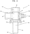
- Fig. 4 is an explanatory view showing a cross section of the snap tap 12.
- the snap tap 12 includes: an upper water passing port 25 formed on an upper portion of a snap tap base body 23; and a side water passing port 26 formed on a side portion of the snap tap base body 23.
- an opening and closing shaft 24 water supplied from a metal sleeve 12e side disposed on a lower portion of the snap tap base body 23 can be selectively supplied to the upper water passing port 25 or the side water passing port 26.
- the snap tap 12 includes: a water passing sleeve 12a which forms a portion of a water passing pipe passage; a water inflow portion 12b and a water outflow portion 12c disposed in front of and behind the water passing sleeve 12a; and an approximately spherical valve element 12d disposed at the center of the water passing sleeve 12a.
- the snap tab 12 forms a ball valve having a water diverting function.
- the snap tap 12 is configured such that the valve element 12d is disposed in the middle of the water passing sleeve 12a for allowing passing of water in the water passing pipe passage and for stopping the passing of water, and an opening or closing operation of a water diverting passage is performed by operating the opening and closing shaft 24 of the valve element 12d.
- the snap tap 12 is disposed at a blanched portion which is communicably connected to the water diverting port 15 formed in the water pipe 11 and forms a blanched passage.
- a cylindrical metal sleeve 12e is inserted into the water diverting port together with a rubber packing 16 described later in a state where the metal sleeve 12e forms an integral part of the snap tap mounting jig A.
- the metal sleeve 12e is integrally connected to the water passing pipe passage of the snap tap 12.
- the metal sleeve 12e is inserted into the inside of the water pipe 11 in a penetrating and projecting manner from the water diverting port 15 together with the rubber packing 16 fitted on an outer periphery of the metal sleeve 12e.
- a projecting distal end portion of the metal sleeve 12e is bent and caulked to the water diverting port 15 by a diameter enlarging roller which forms a main part of the snap tap mounting jig A according to the present invention. With such a configuration, the snap tap 12 is connected and fixed to the water diverting port 15.
- Fig. 5A shows the external appearance of the rubber packing 16
- Fig. 5B shows a cross section of the rubber packing 16.
- the rubber packing 16 is formed of: a flange portion 16a which forms an upper half portion of the rubber packing 16; and a cylindrical mounting portion 16b which forms a lower half portion of the rubber packing 16.
- a loose fitting margin 16c is formed between an inner peripheral surface of the upper half portion and the metal sleeve 12e
- a fitting margin 16d is formed between an inner peripheral surface of the lower half portion and the metal sleeve 12e.
- a stepped tapered portion 16e is formed for allowing smooth passing of the metal sleeve 12e at the boundary portion when the metal sleeve 12e is inserted into the rubber packing 16.
- a locking stepped portion 16f is formed due to a difference in diameter between the flange portion 16a and the mounting portion 16b, and the locking stepped portion 16f is brought into contact with a periphery of and an area the water diverting port 15 and an area in the vicinity of the periphery.
- the cap nut 13 is threadedly mounted on a lower portion of the snap tap base body 23.
- male threads are formed on a peripheral surface of a lower portion of the snap tap base body 23 thus forming a cap nut threadedly engaging portion 23a with which the cap nut 13 is threadedly engaged.
- the cap nut 13 is provided for compressing the rubber packing 16 interposed between the cap nut 13 and an outer surface of a pipe wall of the water pipe 11 at the time of mounting the snap tap 12 on the water diverting port 15 in a caulked state.
- the cap nut 13 functions as a member which ensures water tightness around the water diverting port 15 and the fixing of the snap tap 12 to the water pipe 11.
- a sleeve insertion hole 13c which allows the insertion of the above-mentioned metal sleeve 12e of the snap tap 12 therethrough is formed at the center of the cap nut 13.
- Numeral 13b indicates a cap surface of the cap nut 13.
- a female threaded portion 13e is formed on an inner surface of the cap nut 13, and the female threaded portion 13e is threadedly engaged with the cap nut threadedly engaging portion 23a formed on the peripheral surface of the snap tap base body 23.
- a space formed in the inside of the cap nut 13 and disposed above the cap surface 13b is formed as a space where the cap nut 13 and the snap tap base body 23 are engaged with each other by fitting engagement.
- a rubber packing fitting portion 13f having a recessed shape in which the flange portion 16a of the rubber packing 16 is to be fitted is formed on an outer surface of the cap surface 13b of the cap nut 13.
- a fastening jig engaging portion 13g having a peripheral surface on which engaging grooves are formed is formed on a peripheral wall of a lower portion of the cap nut 13.
- the fastening jig engaging portion 13g is formed so as to be engaged with a fastening jig at the time of making the snap tap base body 23 (snap tap 12) and the cap nut 13 threadedly engage with each other.
- the snap tap mounting jig A is removed.
- the following operation is performed so as to ensure sealing of the snap tap 12 by the rubber packing 16.
- a fastening jig such as a wrench, for example, is engaged with the fastening jig engaging portion 13g of the cap nut 13, and the cup nut 13 threadedly engaged with a lower portion of the snap tap 12 is rotated. Due to the rotation of the cap nut 13, the cap nut 13 is slidably moved relative to the snap tap base body 23 along an axial direction of the rubber packing 16 fitted on the metal sleeve 12e.
- the snap tap 12 is in a state where the snap tap 12 is mounted on the water diverting port 15 in a caulked state as described previously. Accordingly, when the fastening jig engaging portion 13g of the cap nut 13 is rotatably operated in a threaded engagement releasing direction by a wrench or the like, the cap nut 13 is slidably moved toward a water pipe 11 side (that is, in a direction away from the snap tap base body 23) at a threadedly engaged portion of the cap nut 13 with a lower portion of the snap tap base body 23 and hence, the flange portion 16a of the head portion of the rubber packing 16 is compressed between the cap nut 13 and the outer surface of the pipe wall of the water pipe 11.
- the snap tap mounting jig A according to this embodiment is described with reference to Fig. 7 to Fig. 10D .
- the snap tap mounting jig A according to this embodiment is described as a jig which is used in the water diverting port 15 formed in a longitudinal direction.
- the snap tap mounting jig A is used in the vertical snap tap mounting structure where the snap tap 12 is communicably connected to a horizontally-arranged water pipe 11 right above the water pipe 11, and the rubber packing 16 and the metal sleeve 12e are mounted on the water diverting port 15 formed in the peripheral wall of the water pipe 11 from the vertical direction and, in such a state, the rubber packing 16 and the metal sleeve 12e are caulked.
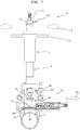
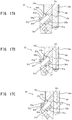
- Fig. 7 is a cross-sectional view showing a state where the snap tap mounting jig A is mounted on and fixed to the gate valve 10
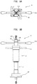
- Fig. 8A and Fig. 8B are explanatory views showing the external appearance of the snap tap mounting jig A
- Fig. 9 is an explanatory view showing the cross-sectional structure of the snap tap mounting jig A.
- a handle operating mechanism where various kinds of handles (an elevating and lowering handle 119, a diameter enlarging handle 118) are collectively arranged is disposed on an upper portion of the snap tap mounting jig A according to this embodiment.
- This handle operating mechanism is mounted on an upper elevating and lowering body 2.
- the upper elevating and lowering body 2 is formed of: a pressing shaft elevating and lowering guide 56; a main shaft 111; a diameter enlarging operating shaft 58; an integral locking mechanism 27; a pull-up nut 117; and an enlarged diameter amount detection mechanism 28.
- the pressing shaft elevating and lowering guide 56 is an approximately cylindrical member having an inner peripheral surface on which female threads 56a are formed, and is threadedly engageable with male threads 3a formed on an outer peripheral surface of a diameter enlarging device body 3.
- a lower end flange 30 is formed on a lower portion of the diameter enlarging device body 3, and the diameter enlarging device body 3 is integrally connectable to the jig connecting flange 10i formed on the upper portion of the gate valve 10 by way of the lower end flange 30. Accordingly, along with the rotation of the pressing shaft elevating and lowering guide 56, the whole upper elevating and lowering body 2 is elevated or lowered relative to the diameter enlarging device body 3 mounted on and fixed to the jig connecting flange 10i.
- the main shaft 111 is formed of: a sleeve pushing pipe 54 which extends downward from the center of the snap tap mounting jig A in a longitudinal direction; an eccentrically movable shaft 52 which forms a roller shaft passing through the inside of the sleeve pushing pipe 54; and an eccentrically movable bearing 53 which is interposed in a cross-sectional space formed between the eccentrically movable shaft 52 and the sleeve pushing pipe 54 and stably supports the eccentrically movable shaft 52 in the inside of the sleeve pushing pipe 54 (see Fig. 10A ).
- a lower portion of the sleeve pushing pipe 54 is formed into a cylindrical shape having a wall thickness larger than a wall thickness of an upper portion of the sleeve pushing pipe 54, and a contact end 54a formed on a lower end of the sleeve pushing pipe 54 is configured to be brought into contact with an upper portion of the snap tap 12 (an edge portion of the upper water passing port 25).
- a diameter enlarging head 57 which is rotated simultaneously due to the rotation of the eccentrically movable shaft 52 is connected to a lower end of the eccentrically movable shaft 52 which passes through the sleeve pushing pipe 54.
- the rubber packing 16 is detachably mounted on a recessed portion 57a formed on a peripheral surface of a lower portion of the diameter enlarging head 57 together with the snap tap 12. In such a state, the rubber packing 16 is in a state where the rubber packing 16 is also fitted on an outer periphery of the metal sleeve 12e of the snap tap 12.
- a diameter enlarging roller 51 is mounted on the diameter enlarging head 57 obliquely toward an oblique upward direction.
- the diameter enlarging roller 51 forms one of technical features of the present invention, and is described in detail later.
- the eccentrically movable shaft 52 rotates at the position eccentric from the center of the main shaft 111. Accordingly, the diameter enlarging roller 51 obliquely mounted on the diameter enlarging head 57 is projectable to the outside of an outer diameter of the main shaft 111, that is, to the outside of an outer diameter of the sleeve pushing pipe 54, and is retractable to the inside of the outer diameter of the main shaft 111, that is, to the inside of the outer diameter of the sleeve pushing pipe 54.
- the diameter enlarging roller 51 when the diameter enlarging roller 51 is retracted to the cross-sectional space formed between the eccentrically movable shaft 52 and the sleeve pushing pipe 54, the diameter enlarging head 57 can pass through the water diverting port 15 while keeping such a state. Thereafter, by allowing the diameter enlarging roller 51 to advance forward from the water diverting port 15 and by rotating the diameter enlarging roller 51, the diameter enlarging roller 51 is brought into a state where the diameter enlarging roller 51 projects outward from the cross-sectional space formed between the eccentrically movable shaft 52 and the sleeve pushing pipe 54.
- the diameter enlarging roller 51 can be displaced to a position where the diameter enlarging roller 51 can caulk the rubber packing 16 and the metal sleeve 12e which are positioned around the water diverting port 15.
- a slide member 90 for preventing a seizure brought about by a friction between an outer peripheral surface of the eccentrically movable bearing 53 and an inner peripheral surface of the metal sleeve 12e is mounted on the outer peripheral surface of the eccentrically movable bearing 53 which is brought into contact with the inner peripheral surface of the metal sleeve 12e.
- the seizure preventing slide member 90 is formed of an elongated plate member having an arcuate shape on one side, is mounted on a portion of a peripheral surface of the eccentrically movable bearing 53 by bolts 90a.
- the slide member 90 is made of MC nylon so that the slide member 90 is smoothly slidable in the metal sleeve 12e.
- handles for respectively operating the sleeve pushing pipe 54, the eccentrically movable shaft 52, the eccentrically movable bearing 53 and the like which form the main shaft 111 are collectively arranged as the handle operating mechanism.
- Symbol 118 indicates a diameter enlarging handle
- symbol 119 indicates an elevating and lowering handle.
- a head advancing and retracting lever 116 is disposed above the diameter enlarging handle 118, and the pull-up nut 117 is threadedly engaged with the eccentrically movable shaft 52 above the head advancing and retracting lever 116.
- the head advancing and retracting lever 116 is provided for advancing or retracting the diameter enlarging roller 51 which is mounted on the diameter enlarging head 57 obliquely to the outside or the inside of the outer diameter of the main shaft 111 by eccentrically rotating the eccentrically movable shaft 52.
- the head advancing and retracting lever 116 is disposed on the key connection block 60 which forms an integral locking mechanism 27 described later.
- the pull-up nut 117 is provided for performing a pull-up operation of the eccentrically movable shaft 52, mainly, a pull-up operation of the diameter enlarging head 57 which advances to the outside of the outer diameter of the main shaft 111.
- a pull-up operation using the pull-up nut 117 a distal end opening portion of the metal sleeve 12e which is made to project into the inside of the water pipe 11 is deformed by being applied with a predetermined pressure corresponding to a pull-up amount of the pull-up nut 117 by the diameter enlarging roller 51 obliquely mounted on the diameter enlarging head 57.
- the diameter enlarging handle 118 is provided for rotating the main shaft 111 in a state where the diameter enlarging roller 51 obliquely mounted on the diameter enlarging head 57 is brought into contact with an opening portion of the distal end of the metal sleeve 12e.
- the diameter enlarging handle 118 is disposed on a diameter enlarging operating shaft 58 connected to an upper portion of the main shaft 111.
- the diameter enlarging handle 118 While rotating the main shaft 111 by the diameter enlarging handle 118, a pulling force of the eccentrically movable shaft 52 generated by the above-mentioned pull-up nut 117 is applied to an end portion of the metal sleeve 12e so that the distal end portion of the opening of the metal sleeve 12e is bent toward the outside in a folded-back state. That is, the diameter enlarging handle 118 is disposed on the diameter enlarging operating shaft 58 formed on an upper end of a pressing shaft elevating and lowering guide 56, and functions as a handle for rotating the main shaft 111 about an axis of the main shaft 111.
- the integral locking mechanism 27 is formed of: a key block 59 fixedly mounted on an upper end surface of the diameter enlarging operating shaft 58; a key connecting block 60 connected to an upper end surface of the key block 59 in an interlocking manner; and a washer 61 disposed on an upper surface of the key connecting block 60 in an overlapping manner.
- an eccentrically movable shaft passing hole 59a is formed in the key block 59 at an eccentric position from the center of the key block 59, engaging grooves 59b which communicate with the eccentrically movable shaft passing hole 59a are formed on an upper surface of the key block 59, and bolt holes 59c used for integrally connecting the key block 59 to the diameter enlarging operation shaft 58 disposed below the key block 59 are formed in the key block 59 in the vicinity of a periphery of the key block 59.
- tenons 60a are formed on a lower surface of the key connecting block 60 in a projecting manner.
- the tenons 60a engage with the engaging grooves 59b formed in the key block 59 thus forming an integral locking mechanism 27 where the key block 59 and the key connecting block 60 are rotated integrally.
- An H-shaped engaging hole 60b is formed at the center of the key connecting block 60.
- the eccentrically movable shaft 52 passes through the H-shaped engaging hole 60b and engages with the H-shaped engaging hole 60b in a state where the key connecting block 60 and the eccentrically movable shaft 52 are simultaneously and integrally rotated with each other and, at the same time, the eccentrically movable shaft 52 can be vertically elevated and lowered.
- the snap tap mounting jig A having such a configuration is integrally connected to the gate valve 10 in such a manner that the lower end flange 30 formed on a lower end of the cylindrical diameter enlarging device body 3 is placed on and fixed to the jig connecting flange 10i of the gate valve 10.
- a hollow portion of the diameter enlarging device body 3 communicates with the jig passing passage 10a of the gate valve 10, and the diameter enlarging head 57 which passes through the inside of the diameter enlarging device body 3 passes the jig passing passage 10a of the gate valve 10 and advances to the water diverting port 15 of the water pipe 11 together with the snap tap 12 and the rubber packing 16.
- the rubber packing 16 on the lower end of the main shaft 111 moves to the water diverting port 15 below the rubber packing 16 due to a lowering action of the above-mentioned elevating and lowering mechanism.
- a flange portion 16a of the rubber packing 16 is brought into contact with a peripheral wall surface of the water diverting port 15 by the contact end 54a of the sleeve pushing pipe 54 and, thereafter, by further pushing the flange portion 16a so as to compress the flange portion 16a, a mounting portion 16b of the rubber packing 16 is inserted into the water diverting port 15.
- the distal-end opening portion 12f of the metal sleeve 12e passes the inner periphery of the rubber packing 16 and projects to the inside of the water pipe 11.
- the diameter enlarging head 57 disposed on the lower end of the main shaft 111 is brought into a state where the diameter enlarging head 57 projects to the further inside of the water pipe 11 from the water diverting port 15 than the distal-end opening portion 12f of the metal sleeve 12e which projects to the inside of the water pipe 11 from the water diverting port 15.
- the diameter enlarging head 57 is brought into a state where the diameter enlarging roller 51 mounted on the diameter enlarging head 57 obliquely is retracted to the inside of the outer diameter of the main shaft 111.
- the diameter enlarging roller 51 mounted on the diameter enlarging head 57 obliquely is made to advance to the outside of the outer diameter of the main shaft 111. Further, by operating the pull-up nut 117, the diameter enlarging roller 51 is brought into contact with the distal-end opening portion 12f of the metal sleeve 12e by a predetermined pressure.
- the eccentrically movable shaft 52 and the eccentrically movable bearing 53 are locked such that the eccentrically movable shaft 52 and the eccentrically movable bearing 53 are rotated integrally with each other, and by rotating the diameter enlarging handle 118, the eccentrically movable shaft 52 and the eccentrically movable bearing 53 are rotated integrally with each other.
- a diameter of the distal-end opening portion 12f of the metal sleeve 12e is expanded in a downwardly spreading manner so that the metal sleeve 12e is caulked to the water diverting port 15 of the water pipe 11 together with the rubber packing 16.
- the distal-end opening portion 12f of the metal sleeve 12e can be folded toward the outside in a fold-back manner.
- the snap tap mounting jig A mounted on the jig connecting flange 10i of the gate valve 10 is removed, and the gate valve 10 per se is also removed from the water pipe 11. Thereafter, a fastening jig is engaged with the fastening jig engaging portion 13g of the cap nut 13 and the rubber packing 16 is further compressed by the cap nut 13 thus finishing an operation of forming the snap tap 12.
- a diameter of the distal-end opening portion 12f of the metal sleeve 12e can be enlarged with a small rotational force. Further, a possibility of buckling which may occur at the time of enlarging the diameter of the distal-end opening portion 12f of the metal sleeve 12e can be eliminated so that accuracy of an enlarged diameter amount can be enhanced.
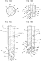
- a peripheral surface of the diameter enlarging roller 51 is formed into a recessed portion having a Japanese-hand-drum shape (hyperbolic shape), a roller shaft 51a of the diameter enlarging roller 51 is disposed in a spanning manner in a roller accommodating chamber 51b which is formed in the diameter enlarging head 57 obliquely, and the diameter enlarging roller 51 is mounted on the roller shaft 51a obliquely.
- a substantially upper half portion of the recessed portion of the peripheral surface of the diameter enlarging roller 51 mounted obliquely is formed as a tapered portion 51c, and a substantially lower half portion of the recessed portion of the diameter enlarging roller 51 mounted obliquely is formed as a rounded portion 51d. Accordingly, the substantially upper half portion forms an inclined straight flat surface, and the rounded portion 51d is contiguously formed with an end edge of the substantially upper half portion. Further, as shown in Fig.
- an inclination angle of the obliquely mounted diameter enlarging roller 51 is set such that an angleamade between an imaginary straight line Y orthogonal to an axis X of the eccentrically movable shaft 52(main shaft 111) and the tapered portion 51c (angle of depression ⁇ ) falls within a range of from 65 degrees to 77 degrees.
- the rounded portion 51d is formed contiguously with the straight flat surface of the tapered portion 51c by curving a portion of the diameter enlarging roller 51 in a semicircular shape so that the diameter enlarging portion 51 is deformed into a hyperbolic (Japanese-hand-drum) shape.
- a portion of the diameter enlarging roller 51 is deformed into a hyperbolic (Japanese-hand-drum) shape.
- the end edge of the metal sleeve 12e is enlarged in a flat funnel shape along the tapered portion 51c so that the end edge of the metal sleeve 12e can be enlarged in an elastic region of the end of the sleeve pipe with a small diameter enlarging force.
- the rounded portion 51d of the peripheral surface plastically deforms the end of the sleeve pipe which is enlarged in a flat shape into a shape similar to a round true semicircular arc.
- the edge of the metal sleeve 12e is elastically deformed into a flat funnel-like tapered shape in a preceding stage and hence, the end edge of the metal sleeve 12e can be easily plastically deformed into a true semicircular arcuate shape having a rounded shape in a succeeding stage. Accordingly, a diameter enlarging force can be reduced so that it is possible to prevent the occurrence of deformation buckling on the distal end or the upper portion of the metal sleeve 12e.
- the peripheral surface shape of the diameter enlarging roller 51 is formed in two stages by the tapered portion 51c which is a region where the peripheral surface shape of the diameter enlarging roller 51 is elastically deformed, and the rounded portion 51d which is a region where the peripheral surface shape of the diameter enlarging roller 51 is plastically deformed. Accordingly, this embodiment can acquire an advantageous effect that a fold-back diameter enlarging operation can be performed without applying a large load to the above-mentioned peripheral members.
- a stress applied to a terminal end flange portion 51g of the diameter enlarging roller 51 is increased thus giving rise to an undesirable situation where buckling is likely to easily occur.
- a yield stress for example, when the angle ⁇ is below 65 degrees, an inclination angle ⁇ of the roller shaft 51a with respect to the axis X on an acute angle side is increased, that is, the diameter enlarging roller 51 becomes excessively close to the horizontal so that the plastic deformation is already performed at the tapered portion 51c.
- a diameter enlarging stress at the tapered portion 51c pushes the diameter enlarging roller 51 in a direction toward the start end flange portion 51h, and the rounded portion 51d pushes the diameter enlarging roller 51 in a direction toward the terminal end flange portion 51g.
- the difference between a force toward a terminal end flange portion 51g side in an axial direction of the roller shaft 51a which is generated along with the plastic deformation of the metal sleeve 12e at the rounded portion 51d and a force toward a start end flange portion 51h side in the axial direction of the roller shaft 51a which is generated along with the elastic deformation of the metal sleeve 12e at the tapered portion 51c becomes a pressure applied to an inner wall of the roller accommodating chamber 51b.
- the diameter enlarging roller 51 can sufficiently perform a plastic deformation function without imparting a large deformation force to the diameter enlarging roller 51.
- a frictional force generated between a lower end surface 51j and the roller accommodating chamber 51b it is possible to avoid the extreme wear.
- a recessed groove portion 51e is formed on an upper end surface 51i (start end surface) and a lower end surface 51j (terminal end surface) of the obliquely mounted diameter enlarging roller 51, and a shim 51f is fitted into the respective recessed groove portions 51e. That is, the diameter enlarging roller 51 is accommodated in the roller accommodating chamber 51b of the diameter enlarging head 57 in a loosely fitted state, and upper and lower end surfaces 51i, 51j of the obliquely mounted diameter enlarging roller 51 are brought into close contact with a peripheral wall surface of the roller accommodating chamber 51b which is obliquely formed.
- the shims 51f are interposed between the upper and lower end surfaces 51i, 51j of the obliquely mounted diameter enlarging roller 51 and the accommodating surface of the roller accommodating chamber 51b so as to ensure the smooth rotation of the diameter enlarging roller 51.
- the shims 51f are accurately fitted into the recessed groove portions 51e and hence, undesired removal or the non-uniform wear of the shims 51f can be prevented.
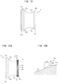
- the snap tap mounting jig A also includes an enlarged diameter amount detection mechanism 28 for detecting an enlarged diameter amount of the distal end of the metal sleeve 12e brought about by the diameter enlarging roller 51.
- the enlarged diameter amount detection mechanism 28 is configured to indicate an elevation amount and a rotation amount of the eccentrically movable shaft 52 as an enlarged diameter amount using a scale marked on an enlarged diameter amount detection nut 55 shown in Fig. 19 .
- the enlarged diameter amount detection mechanism 28 is formed of: the pull-up nut 117 (see Fig. 18A and Fig. 18B ) which is disposed in an overlapping manner on an upper surface of the washer 61 and has an upper-end recessed portion 117a; the enlarged diameter amount detection nut 55 which is formed of a lower cylindrical portion 55a having an outer diameter which allows the insertion of the lower cylindrical portion 55a in the upper-end recessed portion 117a of the pull-up nut 117 as shown in Fig. 19A and Fig.
- the enlarged diameter amount detection nut 55 is fixed to the eccentrically movable shaft 52 by the fixing nut 62. Accordingly, when the eccentrically movable shaft 52 is pulled up, the scale marked on the lower cylindrical portion 55a of the enlarged diameter amount detection nut 55 is gradually exposed from the upper-end recessed portion 117a of the pull-up nut 117.
- An exposure amount of the scale indicates a pull-up amount of the eccentrically movable shaft 52, that is, a fold-back amount and an enlarged diameter amount of the sleeve and hence, a fold-back state of the metal sleeve 12e can be checked by detecting an enlarged diameter amount of the sleeve in the diameter enlarging device body 3 whose inside is not viewable in a see-through manner whereby a mounting state and a sealing state of the snap tap 12 can be checked.
- Fig. 21 shows a modification of a diameter enlarging roller which can be used in place of the previously-mentioned diameter enlarging roller 51.
- constitutional elements substantially equal to the above-mentioned constitutional elements are given the same symbols, and the description of these constitutional elements is omitted.
- a diameter enlarging roller 71 has substantially the same configuration as the previously-mentioned diameter enlarging roller 51.
- the diameter enlarging roller 71 differs from the above-mentioned diameter enlarging roller 51 with respect to a point that a tapered portion 51c is shorter than the tapered portion 51c of the diameter enlarging roller 51, and a diameter of a start end flange portion 51h is smaller than a diameter of a terminal end flange portion 51g.
- an area of the tapered portion 51c can be made small so that a diameter enlarging caulking operation can be performed while reducing a sliding friction generated between the tapered portion 51c and a sleeve inner peripheral surface.
- a friction portion is formed on the diameter enlarging roller for performing a diameter enlarging operation of the sleeve more efficiently.
- a diameter enlarging operation of the sleeve is performed as follows.
- the diameter enlarging head 57 is exposed to the outside of the sleeve by rotating the eccentrically movable shaft 52, the sleeve is brought into contact with the diameter enlarging roller by pulling up the eccentrically movable shaft 52, and a caulking operation is performed while making the diameter enlarging roller roll by the sleeve end portion in a state where the diameter enlarging handle 11 is rotated in a state where the sleeve is deformed.
- Fig. 22A is an explanatory view showing a diameter enlarging roller 73 on which a friction portion 72 is formed by employing the diameter enlarging roller 71 shown in Fig. 21 as a base
- Fig. 22B is an enlarged cross-sectional view of portions indicated by symbols P and Q in Fig. 22A .
- the diameter enlarging roller 73 has substantially the same configuration as the diameter enlarging roller 71, the diameter enlarging roller 73 differs in structure from the diameter enlarging roller 71 with respect to a point that the friction portion 72 is formed on a start end flange portion 51h which is positioned on an upper end side of a recessed portion formed of a tapered portion 51c and a rounded portion 51d.
- the friction portion 72 of the diameter enlarging roller 73 is formed ranging from the start end flange portion 51h to an upper region 51k disposed in the vicinity of a start end flange portion 51h side of the tapered portion 51c. Further, it is not always necessary to form the friction portion 72 as shown in Fig. 22A . That is, it is sufficient that the friction portion 72 is formed at least on the start end flange portion 51h where the sleeve is brought into contact with the diameter enlarging roller first at the time of expanding the sleeve. Further, the friction portion 72 may be formed up to the tapered portion 51c and the rounded portion 51d including the start end flange portion 51h.
- the friction portion 72 is formed by forming a plurality of grooves 72a as friction structural members on a circumference of the diameter enlarging roller 73 (start end flange portion 51h) at predetermined intervals.
- the friction portion 72 has the crest and valley structure formed of crest portions 72c and valley portions 72d where the crest portion 72c and the valley portion 72d are alternately and repeatedly formed, wherein the difference between the crest portion 72c and the valley portion 72d, that is, a groove depth is gradually decreased from the start end flange portion 51h to the tapered portion 51c.
- a load applied to the diameter enlarging roller and a load applied to the members around the diameter enlarging roller which are generated along with the formation of the friction portion can be reduced, and marks formed on the expanded portion of the sleeve attributed to the contact with the friction portion can be reduced.
- the diameter enlarging roller 74 may be formed by forming the friction portion 72 by employing the diameter enlarging roller 51 as a base as shown in Fig. 23 .
- Fig. 24A and Fig. 24B show a further modification of the diameter enlarging roller provided with a friction portion.
- Fig. 24A is an explanatory view showing a configuration of a diameter enlarging roller 75
- Fig. 24B is an enlarged cross-sectional view of a portion of the diameter enlarging roller 75 indicated by symbol P and a portion of the diameter enlarging roller 75 indicated by Q in Fig. 24A .
- the diameter enlarging roller 75 has substantially the same configuration as the diameter enlarging roller 74. However, the diameter enlarging roller 75 differs in structure from the diameter enlarging roller 74 with respect to a point that a friction structural member which forms a friction portion 77 is constituted of a plurality of projecting ridge members 76 which are formed in an extending manner from a start end flange portion 51h along an upper region 51k.
- the plurality of projecting ridge members 76 are formed on a circumference of the diameter enlarging roller 75 (start end flange portion 51h) at predetermined intervals. Due to the formation of the projecting ridge members 76, at the time of enlarging a diameter of the sleeve, while surely allowing the rotational following of the diameter enlarging roller 75 in a direction toward a sleeve inner peripheral surface while generating a frictional force mainly in a circumferential direction of the diameter enlarging roller 75 between the diameter enlarging roller 75 and a sleeve, the slide resistance of the sleeve along the tapered portion 51c and the rounded portion 51d (recessed portion) from the start end flange portion 51h can be suppressed as much as possible. Accordingly, a load applied to the diameter enlarging roller and a load applied to the peripheral member of the diameter enlarging
- the friction portion 77 has the crest and valley structure made by the repetition of crest portions 72c which are peak portions of the projecting ridge members 76 and valley portions 72d which are formed between the projecting ridge members 76.
- Peaks of the crest portions 72c of the friction portion 77 are rounded, and are formed into obtuse peaks and hence, marks formed on the sleeve which is brought into contact with the friction portion 77 due to contacting of the sleeve with the friction portion 77 can be reduced as much as possible.
- a rotational force of the diameter enlarging handle can be efficiently transmitted to the diameter enlarging roller and hence, a force in a pull-up direction applied to the diameter enlarging roller can be decreased whereby lifetimes of members around the diameter enlarging roller can be prolonged by decreasing wear on these members.
- the diameter enlargement cannot be performed unless a large force is applied to the diameter enlarging handle.
- seizure of the diameter enlarging roller can be eliminated and hence, it is possible to reduce a force applied to the diameter enlarging handle.
Landscapes
- Engineering & Computer Science (AREA)
- General Engineering & Computer Science (AREA)
- Mechanical Engineering (AREA)
- Health & Medical Sciences (AREA)
- Life Sciences & Earth Sciences (AREA)
- Hydrology & Water Resources (AREA)
- Public Health (AREA)
- Water Supply & Treatment (AREA)
- Branch Pipes, Bends, And The Like (AREA)
- Gasket Seals (AREA)
- Domestic Plumbing Installations (AREA)
Claims (7)
- Outillage de montage de robinet instantané (A) destiné à assurer le montage d'un robinet instantané (12) sur un orifice de prélèvement d'eau (15) formé sur une conduite d'eau (11) par perçage, dans lequel
l'orifice de prélèvement d'eau (15) comporte une garniture en caoutchouc (16) montée sur une extrémité distale d'un arbre principal (111) de l'outillage de montage de robinet instantané (A), l'arbre principal (111) présentant un diamètre externe, une partie d'extrémité distale d'ouverture (12f) d'un manchon métallique (12e) assemblée librement sur une surface périphérique interne de la garniture en caoutchouc est configurée de manière à pouvoir être insérée et s'étendre à l'intérieur de la conduite d'eau, l'outillage de montage de robinet instantané (A) comprenant :un arbre pouvant être déplacé de manière excentrique (52) présentant une extrémité inférieure et étant configuré de manière à être inséré dans l'arbre principal (111) suivant une direction longitudinale,une tête d'élargissement de diamètre (57),un rouleau d'élargissement de diamètre (51) monté sur l'extrémité inférieure de l'arbre pouvant être déplacé de manière excentrique (52), obliquement au moyen de la tête d'élargissement de diamètre (57), le rouleau d'élargissement de diamètre (51) étant configuré de manière à avancer ou se rétracter vers l'intérieur ou l'extérieur du diamètre externe de l'arbre principal (111) compte tenu de la rotation excentrique de l'arbre pouvant être déplacé de manière excentrique (52), dans lequelle robinet instantané (12) est configuré de manière à être serti sur l'orifice de prélèvement d'eau de la conduite d'eau (11) par courbure de la partie d'extrémité distale d'ouverture du manchon métallique (12e) vers l'extérieur dans un état rabattu ensemble avec la garniture de caoutchouc (16) compte tenu de la rotation de l'arbre principal (111) tout en amenant le rouleau d'élargissement de diamètre (51) en contact avec la partie d'extrémité distale d'ouverture du manchon métallique (12e) en saillie à l'intérieur de la conduite d'eau (11) dans un état dans lequel le rouleau d'élargissement de diamètre (51) est avancé vers l'extérieur du diamètre externe de l'arbre principal (111), dans lequelle rouleau d'élargissement de diamètre est réalisé en une forme hyperbolique présentant une partie en creux (57a), et la partie en creux est formée de telle sorte qu'une demi-partie sensiblement supérieure du rouleau d'élargissement de diamètre monté obliquement est réalisée en une forme sensiblement conique, et qu'une demi-partie sensiblement inférieure du rouleau d'élargissement de diamètre monté obliquement est réalisée en une forme arrondie, dans lequelle rouleau d'élargissement de diamètre (51) présente une partie de bride d'extrémité initiale (51h) avec laquelle une extrémité distale de la partie d'extrémité distale d'ouverture du manchon métallique est amenée en contact au moment du début de l'élargissement d'un diamètre du manchon métallique (12e) sur un côté d'extrémité supérieure de la partie en creux (57a),caractérisé en ce qu'une partie de frottement (72) est formée sur la partie de bride d'extrémité initiale (51h) dans lequella partie de frottement (72) est réalisée en formant des éléments de frottement structurels (74) à intervalles prédéterminés, la partie de frottement étant configurée de manière à produire un effort de frottement sur une circonférence de la partie de bride d'extrémité initiale (51h). - Outillage de montage de robinet instantané selon la revendication 1, dans lequel un angle d'inclinaison (a) de la partie inclinée du rouleau d'élargissement de diamètre monté obliquement est compris dans une plage d'un angle de dépression de 65 degrés à 77 degrés par rapport à une ligne droite imaginaire (Y) perpendiculaire à l'axe (X) de l'arbre pouvant être déplacé de manière excentrique.
- Outillage de montage de robinet instantané selon la revendication 1 ou 2, dans lequel les éléments de frottement structurels sont formés dans une plage s'étendant de la partie de bride d'extrémité initiale (51h) vers une zone supérieure (51k) de la partie conique, et une profondeur de rainure d'une structure en crête et vallée de la partie de frottement formée des éléments de frottement structurels diminue progressivement en partant de la partie de bride d'extrémité initiale vers la partie conique.
- Outillage de montage de robinet instantané selon la revendication 3, dans lequel les pics des parties de crête (72c) de la structure en crête et vallée sont des pics obtus.
- Outillage de montage de robinet instantané selon l'une quelconque des revendications 1 à 4, dans lequel une partie de rainure en creux (51e) est formée sur une surface d'extrémité supérieure (51i) et une surface d'extrémité inférieure (51j) du rouleau d'élargissement de diamètre, et une cale (51f) est assemblée sur la partie de rainure en creux.
- Outillage de montage de robinet instantané selon l'une quelconque des revendications 1 à 5, dans lequel l'outillage de montage de robinet instantané comprend, afin d'assurer la détection d'une dimension de diamètre élargi d'une extrémité distale du manchon métallique par le rouleau d'élargissement de diamètre, un mécanisme de détection de dimension de diamètre élargi (28) sur une partie d'activation d'extrémité proximale d'un arbre de rouleau présentant une extrémité distale sur laquelle le rouleau d'élargissement de diamètre est formé de manière continue, et le mécanisme de détection de dimension de diamètre élargi est configuré de manière à indiquer une élévation et une valeur de rotation de l'arbre de rouleau en tant que dimension de diamètre élargi au moyen d'une graduation sur un écrou de détection de dimension de diamètre élargi formé de manière unitaire avec l'arbre de rouleau.
- Procédé de montage de robinet instantané (12) sur un orifice de prélèvement d'eau (15) formé sur une conduite d'eau (11) par perçage, sans interrompre l'alimentation en eau, comprenant les étapes de :préparation d'un outillage de montage de robinet instantané (A) destiné à assurer le montage d'un robinet instantané (12) sur un orifice de prélèvement d'eau (15) formé sur une conduite d'eau (11) par perçage ;d'une garniture en caoutchouc (16) présentant une surface périphérique interne ; d'un manchon métallique (12e) présentant une partie d'extrémité distale d'ouverture (12f) ; dans lequel l'outillage de montage de robinet instantané comprend un arbre principal (111) présentant un diamètre externe et une extrémité distale, un arbre pouvant être déplacé de manière excentrique (52) présentant une extrémité inférieure, une tête d'élargissement de diamètre (57) et un rouleau d'élargissement de diamètre (51) présentant une partie de bride d'extrémité initiale (51h) ;assemblage de la garniture en caoutchouc (16) dans l'orifice de prélèvement d'eau (15) formé sur la conduite d'eau (11) en montant la garniture en caoutchouc (16) sur l'extrémité distale de l'arbre principal (111) ;assemblage libre de la partie d'extrémité distale d'ouverture (12f) du manchon métallique (12e) sur la surface périphérique interne de la garniture en caoutchouc, et insertion et mise en saillie à l'intérieur de la conduite d'eau,insertion de l'arbre pouvant être déplacé de manière excentrique (52) dans l'arbre principal (111) suivant une direction longitudinale,montage du rouleau d'élargissement de diamètre (51) sur l'extrémité inférieure de l'arbre pouvant être déplacé de manière excentrique (52) obliquement au moyen de la tête d'élargissement de diamètre (57), le rouleau d'élargissement de diamètre (51) étant configuré de manière à avancer et à se rétracter vers l'intérieur ou l'extérieur du diamètre externe de l'arbre principal (111) compte tenu d'une rotation excentrique de l'arbre pouvant être déplacé de manière excentrique (52) ;sertissage du robinet instantané (12) sur l'orifice de prélèvement d'eau de la conduite d'eau (11) par courbure de la partie d'extrémité distale d'ouverture du manchon métallique (12e) vers l'extérieur dans un état rabattu ensemble avec la garniture en caoutchouc (16) compte tenu de la rotation de l'arbre principal (111) tout en amenant le rouleau d'élargissement de diamètre (51) en contact avec la partie d'extrémité distale d'ouverture du manchon métallique (12e) s'étendant à l'intérieur de la conduite d'eau (11) dans un état dans lequel le rouleau d'élargissement de diamètre (51) est avancé vers l'extérieur du diamètre externe de l'arbre principal (111), dans lequelle rouleau d'élargissement de diamètre présente une forme hyperbolique comportant une partie en creux (57a), et la partie en creux est formée de telle sorte qu'une demi-partie sensiblement supérieure du rouleau d'élargissement de diamètre monté obliquement est réalisée en une forme sensiblement conique, et une demi-partie sensiblement inférieure du rouleau d'élargissement de diamètre monté obliquement est réalisée en une forme arrondie.mise en contact d'une extrémité distale de la partie d'extrémité distale d'ouverture du manchon métallique avec la partie de bride d'extrémité initiale (51h) du rouleau d'élargissement de diamètre (51) au moment du début de l'élargissement d'un diamètre du manchon métallique (12e) sur un côté d'extrémité supérieure de la partie en creux (57a),caractérisé en ce qu'une partie de frottement (72) est formée sur la partie de bride d'extrémité initiale (51h) ; dans lequel la partie de frottement (72) est réalisée en formant des éléments de frottement structurels (74) par intervalles prédéterminés, la partie de frottement étant configurée de manière à produire un effort de frottement sur une circonférence de la partie de bride d'extrémité initiale (51h).
Applications Claiming Priority (3)
| Application Number | Priority Date | Filing Date | Title |
|---|---|---|---|
| JP2015110352 | 2015-05-29 | ||
| JP2016066493A JP6639989B2 (ja) | 2015-05-29 | 2016-03-29 | 分水栓取付用治具 |
| PCT/JP2016/085338 WO2017168832A1 (fr) | 2015-05-29 | 2016-11-29 | Gabarit pour installer des robinets à pression |
Publications (3)
| Publication Number | Publication Date |
|---|---|
| EP3276244A1 EP3276244A1 (fr) | 2018-01-31 |
| EP3276244A4 EP3276244A4 (fr) | 2019-01-16 |
| EP3276244B1 true EP3276244B1 (fr) | 2021-03-24 |
Family
ID=57747748
Family Applications (1)
| Application Number | Title | Priority Date | Filing Date |
|---|---|---|---|
| EP16897048.1A Not-in-force EP3276244B1 (fr) | 2015-05-29 | 2016-11-29 | Gabarit pour installer des robinets à pression |
Country Status (6)
| Country | Link |
|---|---|
| US (1) | US10563804B2 (fr) |
| EP (1) | EP3276244B1 (fr) |
| JP (1) | JP6639989B2 (fr) |
| KR (1) | KR20180125373A (fr) |
| CN (1) | CN107438733B (fr) |
| WO (1) | WO2017168832A1 (fr) |
Families Citing this family (2)
| Publication number | Priority date | Publication date | Assignee | Title |
|---|---|---|---|---|
| US11000930B1 (en) * | 2017-11-10 | 2021-05-11 | Blackhawk Manufacturing Group Inc. | Advanced jig for manufacturing of firearm lower receiver |
| EP4414109A4 (fr) * | 2021-09-24 | 2025-06-25 | Cosmo Koki Co., Ltd. | Machine de perçage |
Family Cites Families (11)
| Publication number | Priority date | Publication date | Assignee | Title |
|---|---|---|---|---|
| US3131953A (en) * | 1961-11-30 | 1964-05-05 | Hays Mfg Co | Valve and means for attaching the same to a conduit |
| US3754731A (en) * | 1972-01-18 | 1973-08-28 | Halkey Roberts Corp | Inflation manifold valve and flange assembly |
| SE380606B (sv) * | 1973-11-30 | 1975-11-10 | Gebelius Sven Runo Vilhelm | Sett att astadkomma anslutning av en rorformad hylsa till en platvegg jemte en anordning for verkstellande av settet |
| JPS5544167A (en) * | 1978-09-25 | 1980-03-28 | Yano Giken Kk | Execution of installation work and equipment for hydraulic control valve |
| JP3258419B2 (ja) * | 1993-03-03 | 2002-02-18 | 株式会社栗本鐵工所 | 分岐管の取付方法及び装置 |
| JPH08232304A (ja) * | 1995-02-24 | 1996-09-10 | Kurimoto Ltd | 分水栓の取付方法及び装置 |
| JP2949070B2 (ja) * | 1996-04-05 | 1999-09-13 | 株式会社栗本鐵工所 | 分水栓の取付装置 |
| JPH11190457A (ja) * | 1997-12-26 | 1999-07-13 | Daiko Seimitsu Kk | ゴムパッキン及び分水栓を水道管に穿孔された分水口に装着するための装置及びシャッター装置並びに分水栓 |
| GB2389245A (en) * | 2002-03-27 | 2003-12-03 | Pratley Invest | Deformable cable gland |
| JP5297296B2 (ja) * | 2009-08-10 | 2013-09-25 | 株式会社水道技術開発機構 | 作業用仕切弁 |
| JP6211060B2 (ja) | 2013-03-21 | 2017-10-11 | ヨネ株式会社 | 分水栓形成方法及び同方法に使用する分水栓取付用治具 |
-
2016
- 2016-03-29 JP JP2016066493A patent/JP6639989B2/ja active Active
- 2016-11-29 WO PCT/JP2016/085338 patent/WO2017168832A1/fr not_active Ceased
- 2016-11-29 KR KR1020177026282A patent/KR20180125373A/ko not_active Withdrawn
- 2016-11-29 EP EP16897048.1A patent/EP3276244B1/fr not_active Not-in-force
- 2016-11-29 CN CN201680016920.XA patent/CN107438733B/zh not_active Expired - Fee Related
- 2016-11-29 US US15/562,042 patent/US10563804B2/en not_active Expired - Fee Related
Non-Patent Citations (1)
| Title |
|---|
| None * |
Also Published As
| Publication number | Publication date |
|---|---|
| JP2016223625A (ja) | 2016-12-28 |
| US10563804B2 (en) | 2020-02-18 |
| US20180195655A1 (en) | 2018-07-12 |
| KR20180125373A (ko) | 2018-11-23 |
| WO2017168832A1 (fr) | 2017-10-05 |
| CN107438733A (zh) | 2017-12-05 |
| EP3276244A4 (fr) | 2019-01-16 |
| JP6639989B2 (ja) | 2020-02-05 |
| EP3276244A1 (fr) | 2018-01-31 |
| CN107438733B (zh) | 2020-06-16 |
Similar Documents
| Publication | Publication Date | Title |
|---|---|---|
| US7748463B2 (en) | Cementing valve | |
| US6241424B1 (en) | Method and apparatus for replacing damaged section of a subsea pipeline without loss of product or entry of seawater | |
| EP3276244B1 (fr) | Gabarit pour installer des robinets à pression | |
| NO971178L (no) | Foringsrör for brönnhull | |
| NO338447B1 (en) | A casing annulus cement foundation system and a method for forming a flange collar constituting a cement foundation | |
| CA2376445C (fr) | Applicateur de bouchons de cimentation | |
| US11761305B2 (en) | Downhole degradable staging tool | |
| US10962163B2 (en) | Apparatus for blocking fluid flow through pipes | |
| US20120223568A1 (en) | Holder Block Assembly for a Cutting Tool Having a Hydraulic Piston and Method | |
| RU2435930C1 (ru) | Способ установки профильного перекрывателя в скважине и устройство для его осуществления | |
| JP6539565B2 (ja) | 止水装置 | |
| JP6685576B2 (ja) | 分岐用スリーブ及び分岐部の形成方法 | |
| JP5485810B2 (ja) | 注入工法および装置 | |
| JP2016223527A (ja) | 分水栓取付構造 | |
| US20050279388A1 (en) | Sink drain adapter for drain cleaning device | |
| JPWO2018167874A1 (ja) | 密栓装置及び密栓方法 | |
| RU64265U1 (ru) | Башмак для установки профильного перекрывателя в скважине | |
| KR19990046704A (ko) | 배관용분기티의마감체결장치 | |
| JP2013032807A (ja) | 配管用コネクタ | |
| JP5164668B2 (ja) | 管体の継手構造、これを備えた管継手及びます | |
| JPH07317987A (ja) | 防錆コア装着工具 | |
| CA3140892A1 (fr) | Outil de creation d'etage degradable en fond de trou | |
| EP3505304A1 (fr) | Ensemble dispositif permettant de monter une unité capteur dans une conduite du liquide sous pression ou de démonter l'unité capteur et procédé correspondant | |
| JP2013076446A (ja) | 穿孔口の閉塞器具、閉塞方法、及び、その閉塞器具の装着機 | |
| CN110984887A (zh) | 用于海上高温高压井堵漏的钻井液导流装置及钻柱 |
Legal Events
| Date | Code | Title | Description |
|---|---|---|---|
| STAA | Information on the status of an ep patent application or granted ep patent |
Free format text: STATUS: THE INTERNATIONAL PUBLICATION HAS BEEN MADE |
|
| PUAI | Public reference made under article 153(3) epc to a published international application that has entered the european phase |
Free format text: ORIGINAL CODE: 0009012 |
|
| STAA | Information on the status of an ep patent application or granted ep patent |
Free format text: STATUS: REQUEST FOR EXAMINATION WAS MADE |
|
| 17P | Request for examination filed |
Effective date: 20171013 |
|
| AK | Designated contracting states |
Kind code of ref document: A1 Designated state(s): AL AT BE BG CH CY CZ DE DK EE ES FI FR GB GR HR HU IE IS IT LI LT LU LV MC MK MT NL NO PL PT RO RS SE SI SK SM TR |
|
| AX | Request for extension of the european patent |
Extension state: BA ME |
|
| A4 | Supplementary search report drawn up and despatched |
Effective date: 20181214 |
|
| RIC1 | Information provided on ipc code assigned before grant |
Ipc: E03B 7/02 20060101ALI20181210BHEP Ipc: F16L 41/08 20060101ALI20181210BHEP Ipc: F16L 41/06 20060101AFI20181210BHEP Ipc: E03B 9/12 20060101ALI20181210BHEP |
|
| DAV | Request for validation of the european patent (deleted) | ||
| DAX | Request for extension of the european patent (deleted) | ||
| GRAP | Despatch of communication of intention to grant a patent |
Free format text: ORIGINAL CODE: EPIDOSNIGR1 |
|
| STAA | Information on the status of an ep patent application or granted ep patent |
Free format text: STATUS: GRANT OF PATENT IS INTENDED |
|
| INTG | Intention to grant announced |
Effective date: 20201103 |
|
| GRAS | Grant fee paid |
Free format text: ORIGINAL CODE: EPIDOSNIGR3 |
|
| GRAA | (expected) grant |
Free format text: ORIGINAL CODE: 0009210 |
|
| STAA | Information on the status of an ep patent application or granted ep patent |
Free format text: STATUS: THE PATENT HAS BEEN GRANTED |
|
| AK | Designated contracting states |
Kind code of ref document: B1 Designated state(s): AL AT BE BG CH CY CZ DE DK EE ES FI FR GB GR HR HU IE IS IT LI LT LU LV MC MK MT NL NO PL PT RO RS SE SI SK SM TR |
|
| REG | Reference to a national code |
Ref country code: GB Ref legal event code: FG4D |
|
| REG | Reference to a national code |
Ref country code: CH Ref legal event code: EP |
|
| REG | Reference to a national code |
Ref country code: IE Ref legal event code: FG4D |
|
| REG | Reference to a national code |
Ref country code: AT Ref legal event code: REF Ref document number: 1374817 Country of ref document: AT Kind code of ref document: T Effective date: 20210415 Ref country code: DE Ref legal event code: R096 Ref document number: 602016055042 Country of ref document: DE |
|
| REG | Reference to a national code |
Ref country code: LT Ref legal event code: MG9D |
|
| PG25 | Lapsed in a contracting state [announced via postgrant information from national office to epo] |
Ref country code: GR Free format text: LAPSE BECAUSE OF FAILURE TO SUBMIT A TRANSLATION OF THE DESCRIPTION OR TO PAY THE FEE WITHIN THE PRESCRIBED TIME-LIMIT Effective date: 20210625 Ref country code: HR Free format text: LAPSE BECAUSE OF FAILURE TO SUBMIT A TRANSLATION OF THE DESCRIPTION OR TO PAY THE FEE WITHIN THE PRESCRIBED TIME-LIMIT Effective date: 20210324 Ref country code: FI Free format text: LAPSE BECAUSE OF FAILURE TO SUBMIT A TRANSLATION OF THE DESCRIPTION OR TO PAY THE FEE WITHIN THE PRESCRIBED TIME-LIMIT Effective date: 20210324 Ref country code: NO Free format text: LAPSE BECAUSE OF FAILURE TO SUBMIT A TRANSLATION OF THE DESCRIPTION OR TO PAY THE FEE WITHIN THE PRESCRIBED TIME-LIMIT Effective date: 20210624 Ref country code: BG Free format text: LAPSE BECAUSE OF FAILURE TO SUBMIT A TRANSLATION OF THE DESCRIPTION OR TO PAY THE FEE WITHIN THE PRESCRIBED TIME-LIMIT Effective date: 20210624 |
|
| PG25 | Lapsed in a contracting state [announced via postgrant information from national office to epo] |
Ref country code: SE Free format text: LAPSE BECAUSE OF FAILURE TO SUBMIT A TRANSLATION OF THE DESCRIPTION OR TO PAY THE FEE WITHIN THE PRESCRIBED TIME-LIMIT Effective date: 20210324 Ref country code: RS Free format text: LAPSE BECAUSE OF FAILURE TO SUBMIT A TRANSLATION OF THE DESCRIPTION OR TO PAY THE FEE WITHIN THE PRESCRIBED TIME-LIMIT Effective date: 20210324 Ref country code: LV Free format text: LAPSE BECAUSE OF FAILURE TO SUBMIT A TRANSLATION OF THE DESCRIPTION OR TO PAY THE FEE WITHIN THE PRESCRIBED TIME-LIMIT Effective date: 20210324 |
|
| REG | Reference to a national code |
Ref country code: NL Ref legal event code: MP Effective date: 20210324 |
|
| REG | Reference to a national code |
Ref country code: AT Ref legal event code: MK05 Ref document number: 1374817 Country of ref document: AT Kind code of ref document: T Effective date: 20210324 |
|
| PG25 | Lapsed in a contracting state [announced via postgrant information from national office to epo] |
Ref country code: NL Free format text: LAPSE BECAUSE OF FAILURE TO SUBMIT A TRANSLATION OF THE DESCRIPTION OR TO PAY THE FEE WITHIN THE PRESCRIBED TIME-LIMIT Effective date: 20210324 |
|
| PG25 | Lapsed in a contracting state [announced via postgrant information from national office to epo] |
Ref country code: SM Free format text: LAPSE BECAUSE OF FAILURE TO SUBMIT A TRANSLATION OF THE DESCRIPTION OR TO PAY THE FEE WITHIN THE PRESCRIBED TIME-LIMIT Effective date: 20210324 Ref country code: AT Free format text: LAPSE BECAUSE OF FAILURE TO SUBMIT A TRANSLATION OF THE DESCRIPTION OR TO PAY THE FEE WITHIN THE PRESCRIBED TIME-LIMIT Effective date: 20210324 Ref country code: LT Free format text: LAPSE BECAUSE OF FAILURE TO SUBMIT A TRANSLATION OF THE DESCRIPTION OR TO PAY THE FEE WITHIN THE PRESCRIBED TIME-LIMIT Effective date: 20210324 Ref country code: CZ Free format text: LAPSE BECAUSE OF FAILURE TO SUBMIT A TRANSLATION OF THE DESCRIPTION OR TO PAY THE FEE WITHIN THE PRESCRIBED TIME-LIMIT Effective date: 20210324 Ref country code: EE Free format text: LAPSE BECAUSE OF FAILURE TO SUBMIT A TRANSLATION OF THE DESCRIPTION OR TO PAY THE FEE WITHIN THE PRESCRIBED TIME-LIMIT Effective date: 20210324 |
|
| PG25 | Lapsed in a contracting state [announced via postgrant information from national office to epo] |
Ref country code: RO Free format text: LAPSE BECAUSE OF FAILURE TO SUBMIT A TRANSLATION OF THE DESCRIPTION OR TO PAY THE FEE WITHIN THE PRESCRIBED TIME-LIMIT Effective date: 20210324 Ref country code: SK Free format text: LAPSE BECAUSE OF FAILURE TO SUBMIT A TRANSLATION OF THE DESCRIPTION OR TO PAY THE FEE WITHIN THE PRESCRIBED TIME-LIMIT Effective date: 20210324 Ref country code: PL Free format text: LAPSE BECAUSE OF FAILURE TO SUBMIT A TRANSLATION OF THE DESCRIPTION OR TO PAY THE FEE WITHIN THE PRESCRIBED TIME-LIMIT Effective date: 20210324 Ref country code: PT Free format text: LAPSE BECAUSE OF FAILURE TO SUBMIT A TRANSLATION OF THE DESCRIPTION OR TO PAY THE FEE WITHIN THE PRESCRIBED TIME-LIMIT Effective date: 20210726 Ref country code: IS Free format text: LAPSE BECAUSE OF FAILURE TO SUBMIT A TRANSLATION OF THE DESCRIPTION OR TO PAY THE FEE WITHIN THE PRESCRIBED TIME-LIMIT Effective date: 20210724 |
|
| REG | Reference to a national code |
Ref country code: DE Ref legal event code: R097 Ref document number: 602016055042 Country of ref document: DE |
|
| PG25 | Lapsed in a contracting state [announced via postgrant information from national office to epo] |
Ref country code: ES Free format text: LAPSE BECAUSE OF FAILURE TO SUBMIT A TRANSLATION OF THE DESCRIPTION OR TO PAY THE FEE WITHIN THE PRESCRIBED TIME-LIMIT Effective date: 20210324 Ref country code: DK Free format text: LAPSE BECAUSE OF FAILURE TO SUBMIT A TRANSLATION OF THE DESCRIPTION OR TO PAY THE FEE WITHIN THE PRESCRIBED TIME-LIMIT Effective date: 20210324 Ref country code: AL Free format text: LAPSE BECAUSE OF FAILURE TO SUBMIT A TRANSLATION OF THE DESCRIPTION OR TO PAY THE FEE WITHIN THE PRESCRIBED TIME-LIMIT Effective date: 20210324 |
|
| PGFP | Annual fee paid to national office [announced via postgrant information from national office to epo] |
Ref country code: DE Payment date: 20211118 Year of fee payment: 6 Ref country code: GB Payment date: 20211119 Year of fee payment: 6 |
|
| PLBE | No opposition filed within time limit |
Free format text: ORIGINAL CODE: 0009261 |
|
| STAA | Information on the status of an ep patent application or granted ep patent |
Free format text: STATUS: NO OPPOSITION FILED WITHIN TIME LIMIT |
|
| PG25 | Lapsed in a contracting state [announced via postgrant information from national office to epo] |
Ref country code: SI Free format text: LAPSE BECAUSE OF FAILURE TO SUBMIT A TRANSLATION OF THE DESCRIPTION OR TO PAY THE FEE WITHIN THE PRESCRIBED TIME-LIMIT Effective date: 20210324 |
|
| PGFP | Annual fee paid to national office [announced via postgrant information from national office to epo] |
Ref country code: FR Payment date: 20211028 Year of fee payment: 6 |
|
| 26N | No opposition filed |
Effective date: 20220104 |
|
| PG25 | Lapsed in a contracting state [announced via postgrant information from national office to epo] |
Ref country code: IS Free format text: LAPSE BECAUSE OF FAILURE TO SUBMIT A TRANSLATION OF THE DESCRIPTION OR TO PAY THE FEE WITHIN THE PRESCRIBED TIME-LIMIT Effective date: 20210724 |
|
| PG25 | Lapsed in a contracting state [announced via postgrant information from national office to epo] |
Ref country code: MC Free format text: LAPSE BECAUSE OF FAILURE TO SUBMIT A TRANSLATION OF THE DESCRIPTION OR TO PAY THE FEE WITHIN THE PRESCRIBED TIME-LIMIT Effective date: 20210324 |
|
| REG | Reference to a national code |
Ref country code: CH Ref legal event code: PL |
|
| PG25 | Lapsed in a contracting state [announced via postgrant information from national office to epo] |
Ref country code: LU Free format text: LAPSE BECAUSE OF NON-PAYMENT OF DUE FEES Effective date: 20211129 Ref country code: BE Free format text: LAPSE BECAUSE OF NON-PAYMENT OF DUE FEES Effective date: 20211130 |
|
| REG | Reference to a national code |
Ref country code: BE Ref legal event code: MM Effective date: 20211130 |
|
| PG25 | Lapsed in a contracting state [announced via postgrant information from national office to epo] |
Ref country code: LI Free format text: LAPSE BECAUSE OF NON-PAYMENT OF DUE FEES Effective date: 20211130 Ref country code: CH Free format text: LAPSE BECAUSE OF NON-PAYMENT OF DUE FEES Effective date: 20211130 |
|
| PG25 | Lapsed in a contracting state [announced via postgrant information from national office to epo] |
Ref country code: IE Free format text: LAPSE BECAUSE OF NON-PAYMENT OF DUE FEES Effective date: 20211129 |
|
| PG25 | Lapsed in a contracting state [announced via postgrant information from national office to epo] |
Ref country code: IT Free format text: LAPSE BECAUSE OF FAILURE TO SUBMIT A TRANSLATION OF THE DESCRIPTION OR TO PAY THE FEE WITHIN THE PRESCRIBED TIME-LIMIT Effective date: 20210324 |
|
| PG25 | Lapsed in a contracting state [announced via postgrant information from national office to epo] |
Ref country code: HU Free format text: LAPSE BECAUSE OF FAILURE TO SUBMIT A TRANSLATION OF THE DESCRIPTION OR TO PAY THE FEE WITHIN THE PRESCRIBED TIME-LIMIT; INVALID AB INITIO Effective date: 20161129 |
|
| REG | Reference to a national code |
Ref country code: DE Ref legal event code: R119 Ref document number: 602016055042 Country of ref document: DE |
|
| PG25 | Lapsed in a contracting state [announced via postgrant information from national office to epo] |
Ref country code: CY Free format text: LAPSE BECAUSE OF FAILURE TO SUBMIT A TRANSLATION OF THE DESCRIPTION OR TO PAY THE FEE WITHIN THE PRESCRIBED TIME-LIMIT Effective date: 20210324 |
|
| GBPC | Gb: european patent ceased through non-payment of renewal fee |
Effective date: 20221129 |
|
| PG25 | Lapsed in a contracting state [announced via postgrant information from national office to epo] |
Ref country code: GB Free format text: LAPSE BECAUSE OF NON-PAYMENT OF DUE FEES Effective date: 20221129 Ref country code: DE Free format text: LAPSE BECAUSE OF NON-PAYMENT OF DUE FEES Effective date: 20230601 |
|
| PG25 | Lapsed in a contracting state [announced via postgrant information from national office to epo] |
Ref country code: FR Free format text: LAPSE BECAUSE OF NON-PAYMENT OF DUE FEES Effective date: 20221130 |
|
| PG25 | Lapsed in a contracting state [announced via postgrant information from national office to epo] |
Ref country code: MK Free format text: LAPSE BECAUSE OF FAILURE TO SUBMIT A TRANSLATION OF THE DESCRIPTION OR TO PAY THE FEE WITHIN THE PRESCRIBED TIME-LIMIT Effective date: 20210324 |
|
| PG25 | Lapsed in a contracting state [announced via postgrant information from national office to epo] |
Ref country code: MT Free format text: LAPSE BECAUSE OF FAILURE TO SUBMIT A TRANSLATION OF THE DESCRIPTION OR TO PAY THE FEE WITHIN THE PRESCRIBED TIME-LIMIT Effective date: 20210324 |
|
| PG25 | Lapsed in a contracting state [announced via postgrant information from national office to epo] |
Ref country code: TR Free format text: LAPSE BECAUSE OF FAILURE TO SUBMIT A TRANSLATION OF THE DESCRIPTION OR TO PAY THE FEE WITHIN THE PRESCRIBED TIME-LIMIT Effective date: 20210324 |