EP3276409A1 - Réseau de pixels, procédé de commande d'affichage, appareil de commande d'affichage et appareil d'affichage - Google Patents
Réseau de pixels, procédé de commande d'affichage, appareil de commande d'affichage et appareil d'affichage Download PDFInfo
- Publication number
- EP3276409A1 EP3276409A1 EP15886006.4A EP15886006A EP3276409A1 EP 3276409 A1 EP3276409 A1 EP 3276409A1 EP 15886006 A EP15886006 A EP 15886006A EP 3276409 A1 EP3276409 A1 EP 3276409A1
- Authority
- EP
- European Patent Office
- Prior art keywords
- subpixel
- view
- sampling region
- pixel
- groups
- Prior art date
- Legal status (The legal status is an assumption and is not a legal conclusion. Google has not performed a legal analysis and makes no representation as to the accuracy of the status listed.)
- Withdrawn
Links
Images





Classifications
-
- G—PHYSICS
- G09—EDUCATION; CRYPTOGRAPHY; DISPLAY; ADVERTISING; SEALS
- G09G—ARRANGEMENTS OR CIRCUITS FOR CONTROL OF INDICATING DEVICES USING STATIC MEANS TO PRESENT VARIABLE INFORMATION
- G09G3/00—Control arrangements or circuits, of interest only in connection with visual indicators other than cathode-ray tubes
- G09G3/001—Control arrangements or circuits, of interest only in connection with visual indicators other than cathode-ray tubes using specific devices not provided for in groups G09G3/02 - G09G3/36, e.g. using an intermediate record carrier such as a film slide; Projection systems; Display of non-alphanumerical information, solely or in combination with alphanumerical information, e.g. digital display on projected diapositive as background
- G09G3/003—Control arrangements or circuits, of interest only in connection with visual indicators other than cathode-ray tubes using specific devices not provided for in groups G09G3/02 - G09G3/36, e.g. using an intermediate record carrier such as a film slide; Projection systems; Display of non-alphanumerical information, solely or in combination with alphanumerical information, e.g. digital display on projected diapositive as background to produce spatial visual effects
-
- G—PHYSICS
- G09—EDUCATION; CRYPTOGRAPHY; DISPLAY; ADVERTISING; SEALS
- G09F—DISPLAYING; ADVERTISING; SIGNS; LABELS OR NAME-PLATES; SEALS
- G09F9/00—Indicating arrangements for variable information in which the information is built-up on a support by selection or combination of individual elements
- G09F9/30—Indicating arrangements for variable information in which the information is built-up on a support by selection or combination of individual elements in which the desired character or characters are formed by combining individual elements
- G09F9/302—Indicating arrangements for variable information in which the information is built-up on a support by selection or combination of individual elements in which the desired character or characters are formed by combining individual elements characterised by the form or geometrical disposition of the individual elements
-
- G—PHYSICS
- G02—OPTICS
- G02B—OPTICAL ELEMENTS, SYSTEMS OR APPARATUS
- G02B30/00—Optical systems or apparatus for producing three-dimensional [3D] effects, e.g. stereoscopic images
- G02B30/20—Optical systems or apparatus for producing three-dimensional [3D] effects, e.g. stereoscopic images by providing first and second parallax images to an observer's left and right eyes
- G02B30/26—Optical systems or apparatus for producing three-dimensional [3D] effects, e.g. stereoscopic images by providing first and second parallax images to an observer's left and right eyes of the autostereoscopic type
- G02B30/27—Optical systems or apparatus for producing three-dimensional [3D] effects, e.g. stereoscopic images by providing first and second parallax images to an observer's left and right eyes of the autostereoscopic type involving lenticular arrays
-
- G—PHYSICS
- G02—OPTICS
- G02B—OPTICAL ELEMENTS, SYSTEMS OR APPARATUS
- G02B30/00—Optical systems or apparatus for producing three-dimensional [3D] effects, e.g. stereoscopic images
- G02B30/20—Optical systems or apparatus for producing three-dimensional [3D] effects, e.g. stereoscopic images by providing first and second parallax images to an observer's left and right eyes
- G02B30/26—Optical systems or apparatus for producing three-dimensional [3D] effects, e.g. stereoscopic images by providing first and second parallax images to an observer's left and right eyes of the autostereoscopic type
- G02B30/30—Optical systems or apparatus for producing three-dimensional [3D] effects, e.g. stereoscopic images by providing first and second parallax images to an observer's left and right eyes of the autostereoscopic type involving parallax barriers
- G02B30/31—Optical systems or apparatus for producing three-dimensional [3D] effects, e.g. stereoscopic images by providing first and second parallax images to an observer's left and right eyes of the autostereoscopic type involving parallax barriers involving active parallax barriers
-
- G—PHYSICS
- G02—OPTICS
- G02F—OPTICAL DEVICES OR ARRANGEMENTS FOR THE CONTROL OF LIGHT BY MODIFICATION OF THE OPTICAL PROPERTIES OF THE MEDIA OF THE ELEMENTS INVOLVED THEREIN; NON-LINEAR OPTICS; FREQUENCY-CHANGING OF LIGHT; OPTICAL LOGIC ELEMENTS; OPTICAL ANALOGUE/DIGITAL CONVERTERS
- G02F1/00—Devices or arrangements for the control of the intensity, colour, phase, polarisation or direction of light arriving from an independent light source, e.g. switching, gating or modulating; Non-linear optics
- G02F1/01—Devices or arrangements for the control of the intensity, colour, phase, polarisation or direction of light arriving from an independent light source, e.g. switching, gating or modulating; Non-linear optics for the control of the intensity, phase, polarisation or colour
- G02F1/13—Devices or arrangements for the control of the intensity, colour, phase, polarisation or direction of light arriving from an independent light source, e.g. switching, gating or modulating; Non-linear optics for the control of the intensity, phase, polarisation or colour based on liquid crystals, e.g. single liquid crystal display cells
- G02F1/133—Constructional arrangements; Operation of liquid crystal cells; Circuit arrangements
- G02F1/136—Liquid crystal cells structurally associated with a semi-conducting layer or substrate, e.g. cells forming part of an integrated circuit
- G02F1/1362—Active matrix addressed cells
-
- G—PHYSICS
- G09—EDUCATION; CRYPTOGRAPHY; DISPLAY; ADVERTISING; SEALS
- G09G—ARRANGEMENTS OR CIRCUITS FOR CONTROL OF INDICATING DEVICES USING STATIC MEANS TO PRESENT VARIABLE INFORMATION
- G09G3/00—Control arrangements or circuits, of interest only in connection with visual indicators other than cathode-ray tubes
- G09G3/20—Control arrangements or circuits, of interest only in connection with visual indicators other than cathode-ray tubes for presentation of an assembly of a number of characters, e.g. a page, by composing the assembly by combination of individual elements arranged in a matrix no fixed position being assigned to or needed to be assigned to the individual characters or partial characters
- G09G3/2003—Display of colours
-
- G—PHYSICS
- G09—EDUCATION; CRYPTOGRAPHY; DISPLAY; ADVERTISING; SEALS
- G09G—ARRANGEMENTS OR CIRCUITS FOR CONTROL OF INDICATING DEVICES USING STATIC MEANS TO PRESENT VARIABLE INFORMATION
- G09G3/00—Control arrangements or circuits, of interest only in connection with visual indicators other than cathode-ray tubes
- G09G3/20—Control arrangements or circuits, of interest only in connection with visual indicators other than cathode-ray tubes for presentation of an assembly of a number of characters, e.g. a page, by composing the assembly by combination of individual elements arranged in a matrix no fixed position being assigned to or needed to be assigned to the individual characters or partial characters
- G09G3/2007—Display of intermediate tones
- G09G3/2074—Display of intermediate tones using sub-pixels
-
- G—PHYSICS
- G09—EDUCATION; CRYPTOGRAPHY; DISPLAY; ADVERTISING; SEALS
- G09F—DISPLAYING; ADVERTISING; SIGNS; LABELS OR NAME-PLATES; SEALS
- G09F9/00—Indicating arrangements for variable information in which the information is built-up on a support by selection or combination of individual elements
- G09F9/30—Indicating arrangements for variable information in which the information is built-up on a support by selection or combination of individual elements in which the desired character or characters are formed by combining individual elements
- G09F9/33—Indicating arrangements for variable information in which the information is built-up on a support by selection or combination of individual elements in which the desired character or characters are formed by combining individual elements being semiconductor devices, e.g. diodes
-
- G—PHYSICS
- G09—EDUCATION; CRYPTOGRAPHY; DISPLAY; ADVERTISING; SEALS
- G09F—DISPLAYING; ADVERTISING; SIGNS; LABELS OR NAME-PLATES; SEALS
- G09F9/00—Indicating arrangements for variable information in which the information is built-up on a support by selection or combination of individual elements
- G09F9/30—Indicating arrangements for variable information in which the information is built-up on a support by selection or combination of individual elements in which the desired character or characters are formed by combining individual elements
- G09F9/35—Indicating arrangements for variable information in which the information is built-up on a support by selection or combination of individual elements in which the desired character or characters are formed by combining individual elements being liquid crystals
-
- G—PHYSICS
- G09—EDUCATION; CRYPTOGRAPHY; DISPLAY; ADVERTISING; SEALS
- G09G—ARRANGEMENTS OR CIRCUITS FOR CONTROL OF INDICATING DEVICES USING STATIC MEANS TO PRESENT VARIABLE INFORMATION
- G09G2300/00—Aspects of the constitution of display devices
- G09G2300/04—Structural and physical details of display devices
- G09G2300/0421—Structural details of the set of electrodes
- G09G2300/0426—Layout of electrodes and connections
-
- G—PHYSICS
- G09—EDUCATION; CRYPTOGRAPHY; DISPLAY; ADVERTISING; SEALS
- G09G—ARRANGEMENTS OR CIRCUITS FOR CONTROL OF INDICATING DEVICES USING STATIC MEANS TO PRESENT VARIABLE INFORMATION
- G09G2300/00—Aspects of the constitution of display devices
- G09G2300/04—Structural and physical details of display devices
- G09G2300/0439—Pixel structures
- G09G2300/0443—Pixel structures with several sub-pixels for the same colour in a pixel, not specifically used to display gradations
-
- G—PHYSICS
- G09—EDUCATION; CRYPTOGRAPHY; DISPLAY; ADVERTISING; SEALS
- G09G—ARRANGEMENTS OR CIRCUITS FOR CONTROL OF INDICATING DEVICES USING STATIC MEANS TO PRESENT VARIABLE INFORMATION
- G09G2300/00—Aspects of the constitution of display devices
- G09G2300/04—Structural and physical details of display devices
- G09G2300/0439—Pixel structures
- G09G2300/0452—Details of colour pixel setup, e.g. pixel composed of a red, a blue and two green components
-
- G—PHYSICS
- G09—EDUCATION; CRYPTOGRAPHY; DISPLAY; ADVERTISING; SEALS
- G09G—ARRANGEMENTS OR CIRCUITS FOR CONTROL OF INDICATING DEVICES USING STATIC MEANS TO PRESENT VARIABLE INFORMATION
- G09G2320/00—Control of display operating conditions
- G09G2320/06—Adjustment of display parameters
- G09G2320/0626—Adjustment of display parameters for control of overall brightness
- G09G2320/0646—Modulation of illumination source brightness and image signal correlated to each other
-
- G—PHYSICS
- G09—EDUCATION; CRYPTOGRAPHY; DISPLAY; ADVERTISING; SEALS
- G09G—ARRANGEMENTS OR CIRCUITS FOR CONTROL OF INDICATING DEVICES USING STATIC MEANS TO PRESENT VARIABLE INFORMATION
- G09G2340/00—Aspects of display data processing
- G09G2340/04—Changes in size, position or resolution of an image
- G09G2340/0457—Improvement of perceived resolution by subpixel rendering
-
- G—PHYSICS
- G09—EDUCATION; CRYPTOGRAPHY; DISPLAY; ADVERTISING; SEALS
- G09G—ARRANGEMENTS OR CIRCUITS FOR CONTROL OF INDICATING DEVICES USING STATIC MEANS TO PRESENT VARIABLE INFORMATION
- G09G2340/00—Aspects of display data processing
- G09G2340/10—Mixing of images, i.e. displayed pixel being the result of an operation, e.g. adding, on the corresponding input pixels
-
- G—PHYSICS
- G09—EDUCATION; CRYPTOGRAPHY; DISPLAY; ADVERTISING; SEALS
- G09G—ARRANGEMENTS OR CIRCUITS FOR CONTROL OF INDICATING DEVICES USING STATIC MEANS TO PRESENT VARIABLE INFORMATION
- G09G5/00—Control arrangements or circuits for visual indicators common to cathode-ray tube indicators and other visual indicators
- G09G5/10—Intensity circuits
Definitions
- the present invention relates to the field of display technologies, in particular to a pixel array, a display driving method, a display driving device and a display device.
- each pixel renders colors by mixing light with several subpixels.
- each pixel may consist of a red subpixel, a green subpixel, and a blue subpixel.
- resolutions of display devices which entails subpixels to become smaller and smaller in size.
- size of subpixels cannot be reduced infinitely due to process limitations.
- a display device of Pentile mode has been proposed in the art to improve the display effect.
- a single pixel may consists of only two subpixels of "red-green” or "blue-green".
- a pixel in the display device of Pentile mode may "borrow” another color from its adjacent pixels to render three primary colors. Therefore, in a display device of Pentile mode, partial subpixels are "shared", which reduces the number of subpixels, achieves an effect of simulating a high resolution under a low resolution, and achieves a higher resolution than an actual resolution in terms of visual effect.
- Naked eye 3D mode is a kind of 3D display mode suitable for display devices of large sizes, which distinguishes between information entering a viewer's left eye and information entering the viewer's right eye (comprising a first view and a second view) by setting gratings so that the viewer may experience 3D effects.
- the naked eye 3D mode has a light barrier grating design, PPI (Pixel per inch) will be significantly reduced, sometimes by half, during being observed, which degrades 3D visual effects.
- PPI Panel per inch
- An object of the present invention is to provide a pixel array, a display driving method, a display driving device and a display device, which overcomes or obviates shortcomings or problems relating to the above mentioned display technologies.
- a pixel array in accordance with embodiments of the present invention is suitable for application of Pentile technologies under 2D/3D display mode.
- the present invention provides a pixel array, comprising a plurality of columns of subpixel groups, each column of subpixel groups comprising M X N subpixels, where N is the number of colors of subpixels, and M is an integer equal or greater than 3; directions in which subpixels of the subpixel groups in odd columns and subpixels of the subpixel groups in even columns are twisted respectively being opposite in a column direction.
- shapes of the subpixels are parallelogram.
- acute angles of the parallelogram are in a range of 70 degree to 90 degree.
- acute angles of the parallelogram are in a range of 82 degree to 85 degree.
- a length ratio of a side of a subpixel in the column direction to a side of the subpixel not in the column direction is [ 1 2 , 1].
- the predetermined number is lower than the number of colors of subpixels comprised in the pixel array.
- the predetermined number may be 2, 3 2 or 1.
- the value of N is 3, and the pixel array is a triangular pixel array.
- length of a side of the subpixel in the column direction is a
- the subpixel groups in odd columns and the subpixel groups in even columns are staggered by 1 2 a in the column direction.
- the present invention also provides a display driving method for driving a 2D display device comprising an pixel array described above according to the present invention, and the display driving method comprises:
- length of a side of a subpixel in a column direction is a
- span of the subpixel in a row direction is b
- the subpixel groups in odd columns and the subpixel groups in even columns are staggered by 1 2 a in the column direction
- the first preset sampling region is a rhombic sampling region; wherein four vertexes of the rhombic sampling region for the subpixel are arranged such that two vertexes are in the same column direction as center of the subpixel and at a distance of 3 2 a from the center of the subpixel respectively, and the other two vertexes are in the same row direction as the center of the subpixel and at a distance of b from the center of the subpixel respectively.
- the step of setting luminance for each subpixel based on color components for color of the subpixel in theoretical pixel elements that are covered by the rhombic sampling region corresponding to the subpixel comprises:
- the present invention also provides a display driving device for driving a display device comprising a pixel array described above, the display driving device comprising:
- the first preset sampling region is a rhombic sampling region; wherein four vertexes of the rhombic sampling region for the subpixel are arranged such that two vertexes are in the same column direction as center of the subpixel and at a distance of 3 2 a from the center of the subpixel respectively, and the other two vertexes are in the same row direction as the center of the subpixel and at a distance of b from the center of the subpixel respectively.
- the present invention also provides a display driving method for driving a 3D display device comprising a grating array and a pixel array described above, the subpixel groups in odd columns being first view pixel groups used for a first view to be displayed; the subpixel groups in even columns being second view pixel groups used for a second view to be displayed; the grating array shielding along the column direction a part of the first view pixel groups on a first side and a part of the second view pixel groups on a second side, the first sides and the second side being opposite sides; the display driving methods comprising:
- length of a side of the subpixel in the column direction is a
- length of the subpixel in a row direction is b
- the second preset sampling region is a rectangular sampling region; wherein four middle points of four sides of the rectangular sampling region for the subpixel are arranged such that two middle points are in the same column direction as center of the subpixel and at a distance of 3 2 a from the center of the subpixel respectively, and the other two middle points are in the same row direction as the center of the subpixel and at a distance of b from the center of the subpixel respectively.
- the step of, for each view, setting luminance for each subpixel used for the view based on color components for color of the subpixel in theoretical pixel elements that are covered by a preset sampling region corresponding to the subpixel and belong to the view comprises:
- the present invention further provides a display driving device for driving a 3D display device comprising a grating array and a pixel array described above, the subpixel groups in odd columns being first view pixel groups used for a first view to be displayed; the subpixel groups in even columns are second view pixel groups used for a second view to be displayed; the grating array being configured to shield along the column direction a part of the first view pixel groups on a first side and a part of the second view pixel groups on a second side, the first sides and the second side being opposite sides; the display driving device comprising:
- length of a side of the subpixel in the column direction is a
- length of the subpixel in a row direction is b
- the second preset sampling region is a rectangular sampling region; wherein four middle points of four sides of the rectangular sampling region for the subpixel are arranged such that two middle points are in the same column direction as center of the subpixel and at a distance of 3 2 a from the center of the subpixel respectively, and the other two middle points are in the same row direction as the center of the subpixel and at a distance of b from the center of the subpixel respectively.
- the present invention further provides a display device comprising a pixel array described above.
- the display device further comprises a display driving device described above.
- the present invention provides the following beneficial effects, i.e. a pixel array according to embodiments of the present invention is suitable for application of Pentile technologies under 2D/3D display mode. Therefore, the visual resolution of the display device may be effectively improved.
- a pixel array, a display driving method, a display driving device and a display device provided by the present invention will be described in detail with the reference to drawings in order to help those ordinarily skilled in the art to better understand solutions of the present invention.
- Fig. 1 is a top view illustrating a pixel array 100 in accordance with an embodiment of the present invention.
- the pixel array 100 comprises a plurality of columns of subpixel groups S 1 , S 2 , S 3 , S 4 , S 5 , S 6 , and each column of subpixel group comprises M X N subpixels: CC 1 -C 9 ; G 1 -G 9 , wherein N is the number of colors (e.g. R, G, B) of the subpixels, and M is an integer equal or greater than 3.
- a direction in which subpixels in the subpixel groups in odd columns, e.g. S 1 , S 3 , S 5 , are twisted i.e. a twisted direction
- a twisted direction of a subpixel may be a tilt direction of the subpixel in a column direction.
- the twisted directions of two subpixels are opposite in the column direction may refer to an arrangement where same sides of the subpixels tilt relative to the column direction on opposite directions.
- subpixels in subpixel group S 1 , S 3 , S 5 in odd column are twisted downwards relative to the column direction, that is, the left sides of these subpixels are tilted downwards (shown by a downwards arrow in Fig. 1 ).
- subpixels in subpixel groups S 2 , S 4 , S 6 in even columns are twisted upwards relative to the column direction, that is, the left sides of these subpixels are tilted upwards (shown by the upwards arrow in Fig. 1 ).
- Sub-pixels in a pixel array according to an embodiment of the present invention may be deformed into a parallelogram by twisting, which is different from conventional shapes of subpixels (e.g., rectangle).
- each subpixel in a pixel array has a shape of parallelogram, optionally, a shape of non-right angled parallelogram.
- sides in a column direction are aligned with respect to the column direction, while sides in a row direction tilt relative to the row direction.
- length of a side in a column direction is a
- length of the subpixel in a row direction is b .
- acute angles of the parallelogram are in a range of 70 degree to 90 degree.
- acute angles of the parallelogram are in a range of 82 degree to 85 degree.
- a length ratio of a side of a subpixel that is in a column direction to a side of the subpixel that is not in the column direction is [ 1 2 , 1].
- the subpixel groups in odd columns and the subpixel groups in even columns are staggered in the column direction.
- sides of subpixels in subpixel groups in odd columns and subpixels in subpixel groups in even columns are staggered with each other in the column direction.
- subpixel groups in odd columns and subpixel groups in even columns are staggered by 1 2 a in the column direction. In this way, subpixels of same colors in the pixel array may be distributed uniformly so as to ensure that the display panel may emit light uniformly.
- N is assumed to be 3
- the pixel array is assumed to be a triangular pixel array.
- a triangular (Delta, written as " ⁇ ") pixel array may refer to an array in which a shape formed by centers of three arbitrarily closest subpixels of different colors is a triangle.
- pixel array shown in Fig. 1 comprises subpixels arranged in 6 columns (S1-S6), 9 rows (G1-G9 or C1-C9), this pixel array is only an example, and solutions of the present invention are not limited thereto.
- a pixel array according to embodiments of the present invention is not only suitable to application of Pentile technologies in 2D display mode, but also suitable to application of Pentile technologies in 3D display mode. Particular solutions will be described in more detail below.
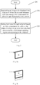
- Fig. 2 is a flow chart illustrating a first exemplary display driving method 200 in accordance with an embodiment of the present invention.
- the display driving method 200 may be used to drive a 2D display device which comprises a pixel array according to embodiments of the present invention.
- the display driving method will be described with the reference to Fig. 3 to Fig. 10 .
- the 2D display device comprises a pixel array 100 as shown in Fig. 1 .
- the pixel array 100 comprises subpixels of three different colors, e.g. red subpixel R, green subpixel G and blue subpixel B. For each subpixel, length of a side in a column direction is a , and length in a row direction is b.
- the display driving method 200 comprises:
- the image to be displayed may be segmented into a plurality of pixel elements, i.e., theoretical pixel elements, based on a pixel resolution that the display device may achieve theoretically.
- Each theoretical pixel element may correspond to a predetermined number of subpixels and color components for colors in each theoretical pixel element may be determined based on colors of corresponding subpixels.
- the area corresponding to a theoretical pixel element is referred to as unit pixel element area.
- unit pixel element area there are a predetermined number of subpixels contained within the unit pixel element area.
- the predetermined number may be set to be smaller than the number of colors of subpixels comprised in the pixel array.
- the predetermined number may be 2, 3 2 , or 1.
- Figs. 3a to 3c are schematic views illustrating three different correspondences between a theoretical pixel element and a subpixel in accordance with embodiments of the present invention.
- the size of an area corresponding to a theoretical pixel element 1 is fixed, and the size of a subpixel in a pixel array may vary (e.g., this may be achieved by controlling sizes of subpixels R/G/B when preparing the pixel array).
- the theoretical pixel element 1 may correspond to a parallelogram region, wherein length of one side of the parallelogram region may correspond to length of a side of a subpixel that is not in the column direction.
- the unit pixel element area of the theoretical pixel element 1 may contain one subpixel, i.e., one theoretical pixel element 1 corresponds to one subpixel, such as blue subpixel B.
- the unit pixel element area may contain 3 2 subpixels, i.e., one theoretical pixel element 1 corresponds to an area of one subpixel (such as blue subpixel B) and a half area of another subpixel (such as green subpixel G) adjacent to the subpixel in the column direction.
- the unit pixel element area may contain 2 subpixels (such as blue subpixel B and green subpixel G), i.e., one theoretical pixel element 1 corresponds to two subpixels adjacent in the column direction.
- Fig. 4 is a schematic view illustrating one theoretical pixel element corresponding to one and a half subpixels in a pixel array as shown in Fig. 1 in accordance with an embodiment of the present invention.
- an image to be displayed may be segmented into a plurality of theoretical pixel elements 1 (in Fig. 4 , only one theoretical pixel element in column S1 and one theoretical pixel element in column S2 are depicted by way of example).
- red color component, green color component and blue color component in each theoretical pixel element 1 may be determined based on subpixels (such as red subpixel R, green subpixel G and blue subpixel B) contained in the unit pixel element area.
- the determination of color components for colors in a theoretical pixel element 1 may be carried out using any suitable technical measure in the art.
- the display driving method 200 further comprises:
- a preset sampling region may be set for each subpixel.
- the preset sampling region may define for a subpixel a range of relevant (e.g., adjacent) subpixels whose colors will be borrowed by the subpixel during image displaying, and therefore the preset sampling region may be a region that contains not only this subpixel but also relevant subpixel(s) (either partially or entirely). Accordingly, the preset sampling region may either partially or entirely cover theoretical pixel element(s) corresponding to the subpixel and its relevant subpixel(s).
- a first preset sampling region corresponding to each subpixel is set as a rhombic sampling region.
- four vertexes of the rhombic sampling region for a subpixel are arranged such that two vertexes are in the same column direction as center of the subpixel and at a distance of 3 2 a from the center of the subpixel respectively, and the other two vertexes are in the same row direction as the center of the subpixel and at a distance of b from the center of the subpixel respectively.
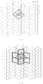
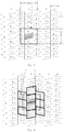
- Fig. 5 is a schematic view illustrating a sampling region 2 of a red subpixel R at row G3, column S3 during 2D displaying.
- Fig. 6 is a schematic view illustrating theoretical pixel elements 1 covered by the sampling region 2 for the red subpixel R as shown in Fig. 5 .
- a rhombic sampling region 2 corresponding to a red subpixel R at row G3, column S3 are arranged such that two vertexes are in the same column direction as center of the red subpixel and at a distance of 3 2 a from the center of the red subpixel respectively (i.e., being positioned at middle points of respective lower sides of two blue subpixels at row G1, column S3 and row G4, column S3 respectively); and the other two vertexes are in the same row direction as the center of the red subpixel and at a distance of b from the center of the red subpixel respectively (i.e., being positioned at middle points of respective lower sides of two blue subpixels at row C3, column S2 and row C3, column S4 respectively).
- the rhombic sampling region 2 of the red subpixel covers at least partial areas of seven different theoretical pixel elements 1.
- Fig. 7 is a schematic view illustrating a sampling region for a blue subpixel B at row G4, column S3 during 2D displaying.
- Fig. 8 is a schematic view illustrating theoretical pixel elements covered by the sampling region for the blue subpixel shown in Fig. 7 .
- a rhombic sampling region 2 corresponding to a blue subpixel B at row G4, column S3 are arranged such that two vertexes are in the same column direction as the center of the blue subpixel and at a distance of 3 2 a from the center of the blue subpixel respectively (i.e., being positioned at middle points of respective lower side of two green subpixels at row G2, column S3 and row G5, column S3 respectively); the other two vertexes are in the same row direction as the center of the blue subpixel and at a distance of b from the center of the blue subpixel respectively (i.e., being positioned at middle points of respective lower side of two green subpixels at row C4, column S2 and row C4, column S4 respectively).
- the rhombic sampling region 2 of the blue subpixel covers at least partial areas of 7 different theoretical pixel elements 1.
- Fig. 9 is a schematic view illustrating a sampling region 2 for a green subpixel G at row G5, column S3 during 2D displaying.
- Fig. 10 is a schematic view illustrating theoretical pixel elements covered by the sampling region for the green subpixel shown in Fig. 9 .
- a rhombic sampling region 2 corresponding to a green subpixel G at row G5, column S3 are arranged such that two vertexes are in the same column direction as the center of the green subpixel and at a distance of 3 2 a from the center of the green subpixel respectively (i.e., being positioned at middle points of respective lower side of two red subpixels at row G3, column S3 and row G6, column S3 respectively); the other two vertexes are in the same row direction as the center of the green subpixel and at a distance of b from the center of the green subpixel respectively (i.e., being positioned at middle points of respective lower side of two red subpixels at row C5, column S2 and row C5, column S4 respectively).
- the rhombic sampling region 2 of the green subpixel covers at least partial areas of 6 different theoretical pixel elements 1.
- a rhombic sampling region may be set in this way so that the whole display area can be completely sampled, while sampling will not be overlapped, thereby avoiding a problem of picture distortion due to incomplete sampling or overlapping sampling.
- luminance of a subpixel may be determined by: for each subpixel, determining overlapping areas between a preset sampling region corresponding to the subpixel and each theoretical pixel element covered by the preset sampling region and color components for the color of the subpixel in each theoretical pixel element; calculating products of overlapping areas corresponding to said each theoretical pixel element and respective determined color components; and setting the luminance of the subpixel based on a sum of the products and an area of the preset sampling region.
- luminance of corresponding subpixel may be set in any other suitable way.
- Fig. 11 is a schematic view illustrating a first exemplary display driving device 1100 in accordance with an embodiment of the present invention.
- the display driving device 1100 may be used to drive 2D display device.
- the 2D display device comprises a pixel array in accordance with an embodiment of the present invention, such as the pixel array 100 shown in Fig. 1 .
- the display driving device 1100 comprises a first image pixel segmenting unit 1110 and a first luminance setting unit 1120.
- the first image pixel segmenting unit 1110 is configured to segment an image to be displayed into a plurality of theoretical pixel elements and determine the color component for colors in each theoretical pixel element.
- the first luminance setting unit 1120 is configured to set luminance for each subpixel based on color components for color of the subpixel in theoretical pixel elements that are covered by a first preset sampling region corresponding to the subpixel.
- the first preset sampling region is a rhombic sampling region.
- four vertexes of the rhombic sampling region for the subpixel are arranged such that two vertexes are in the same column direction as center of the subpixel and at a distance of 3 2 a from the center of the subpixel respectively, and the other two vertexes are in the same row direction as the center of the subpixel and at a distance of b from the center of the subpixel respectively, wherein a is length of a side of a subpixel in the column direction and b is length of the subpixel in the row direction.
- the image pixel segmenting unit 1110 may be configured to perform action(s) in step 101 described with reference to Fig. 2 to Fig. 10
- the first luminance setting unit 1120 may be configured to perform action(s) in step 102 described with reference to Fig. 2 to Fig. 10 .
- detailed descriptions thereof are omitted.
- Fig. 12 is a flow chart illustrating a second exemplary display driving method 1200 in accordance with an embodiment of the present invention.
- the display driving method is used to drive a 3D display device comprising a pixel array according to embodiments of the present invention.
- the display driving method will be described with reference to Fig. 13 to Fig. 19 .
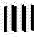
- Fig. 13 is a structural schematic view illustrating a pixel array in accordance with an embodiment of the present invention being comprised in a 3D display device.
- the 3D display device comprises a grating array 5 and a pixel array 4 in accordance with an embodiment of the present invention.
- the pixel array 4 may be the pixel array 100 shown in Fig. 1 .
- the subpixel groups in odd columns are first view pixel groups 6 (comprising a plurality of R1s, G1s and B1s); the subpixel groups in even columns are second view pixel groups 7 (comprising a plurality of R2s, G2s, and B2s).
- the grating array 4 shields along a column direction a part of the first view pixel groups 6 on a first side and a part of the second view pixel groups 7 on a second side, and the first side and the second side are opposite sides.
- the first view pixel groups 6 are used to display a first view
- the second view pixel groups 7 are used to display a second view.
- the first view and the second view enter a viewer's left eye and right eye respectively so that the viewer may obtain 3D perception.
- the pixel array 4 may comprise subpixels of three different colors, e.g. red subpixel R, green subpixel G and blue subpixel B. Length of a side of each subpixel in a column direction is a and length of each subpixel in a row direction is b .
- the display driving method 1200 comprises:
- the first view may be segmented into a plurality of theoretical pixel elements according to the number of pixels that may be achieved by the 3D display device theoretically. Thereafter, red component, green component and blue component in each theoretical pixel element may be determined. Segmentation of a plurality of theoretical pixel elements corresponding to the second view and determination of red component, green component and blue component in each theoretical pixel element may be carried out in a same way.
- one theoretical pixel element corresponds to an area of one subpixel and a half area of another subpixel adjacent to the subpixel in the column direction.
- Step 1202 for each view, setting luminance for each subpixel used for the view based on color components for color of the subpixel in theoretical pixel elements that are covered by a second preset sampling region corresponding to the subpixel and belong to the view.
- a second preset sampling region corresponding to each subpixel is set as a rectangular sampling region.
- four middle points of four sides of the rectangular sampling region for the subpixel are arranged such that two middle points are in the same column direction as center of the subpixel and at a distance of 3 2 a from the center of the subpixel respectively, and the other two middle points are in the same row direction as the center of the subpixel and at a distance of b from the center of the subpixel respectively.
- subpixels R1, B1 and G1 represent subpixels used for the first view and subpixels R2, B2 and G2 represent subpixels used for the second view.
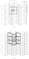
- Fig. 14 is a schematic view illustrating a sampling region 3 for a red subpixel R1 at row G3, column S3 during 3D displaying.
- Fig. 15 is a schematic view illustrating theoretical pixel elements 1 covered by the sampling region 3 for the red subpixel R1 as shown in Fig. 14 .
- the rectangular sampling region 3 of the red subpixel covers at least partial areas of 9 different theoretical pixel elements 1.
- the red subpixel R1 is used for the first view and the theoretical pixel elements belonging to the first view comprises 3 theoretical pixel elements in column S3 where the red subpixel R1 is arranged.
- Fig. 16 is a schematic view illustrating a sampling region 3 for a blue subpixel B1 at row G4, column S3 during 3D displaying.
- Fig. 17 is a schematic view illustrating theoretical pixel elements 1 covered by the sampling region 3 of the blue subpixel B1 shown in Fig. 13 .
- the rectangular sampling region 3 of the blue subpixel B1 covers at least partial areas of 9 different theoretical pixel elements 1.
- the blue subpixel B1 is used for the first view, and therefore the theoretical pixel elements belonging to the first view comprises 3 theoretical pixel elements in column S3 where the blue subpixel B1 is arranged.
- Fig. 18 is a schematic view illustrating a sampling region 3 for a green subpixel G1 at row G5, column S3 during 3D displaying.
- Fig. 19 is a schematic view illustrating theoretical pixel elements 1 covered by the sampling region 3 of the green subpixel G1 as shown in Fig. 18 .
- the rectangular sampling region 3 of the green subpixel covers at least partial areas of 10 different theoretical pixel elements 1.
- the green subpixel G1 is used for the first view, and therefore the theoretical pixel elements belonging to the first view comprises 4 theoretical pixel elements in column S3 where the green subpixel G1 is arranged.
- a rectangular sampling region may be set in this way so that during 3D displaying, the whole display area may be completely sampled, while the sampling will not be overlapped, thereby avoiding problem of picture distortion due to incomplete sampling or overlapping sampling.
- luminance of a subpixel used for a view may be determined by: for each subpixel used for a view, determining overlapping areas between its corresponding preset sampling region and each theoretical pixel element covered by the preset sampling region and belonging to the view and color components for the color of the subpixel in said each theoretical pixel element; calculating products of overlapping areas corresponding to said each theoretical pixel element and the respective determined color components; and setting the luminance of the subpixel based on a sum of the products and an area of the preset sampling region.
- luminance of corresponding subpixels may be set in any other suitable way.
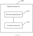
- Fig. 20 is a schematic view illustrating a second exemplary display driving device 2000 in accordance with an embodiment of the present invention.
- the display driving device 2000 is used to drive a 3D display device.
- the 3D display device comprises a grating array and a pixel array according to the embodiment of the present invention.
- the subpixel groups in odd columns are first view pixel groups, that is, the subpixel groups are used for a first view; and the subpixel groups in even columns are second view pixel groups, that is, the subpixel groups are used for the second view.
- the grating array shields along a column direction a part of the first view pixel groups on a first side and a part of the second view pixel groups on a second side, wherein the first side and the second side are opposite sides.
- the display driving device 2000 comprises a second view pixel segmenting unit 2010 and a second luminance setting unit 2020.
- the second view pixel segmenting unit 2010 may be configured to segment the first view and the second view into a plurality of theoretical pixel elements respectively and determine color components for colors in each theoretical pixel element.
- the second luminance setting unit 2020 may be configured to, for each view, set luminance for each subpixel used for the view based on color components for color of the subpixel in theoretical pixel elements that are covered by a second preset sampling region corresponding to the subpixel and belong to the view.
- the second preset sampling region is a rectangular sampling region, wherein four middle points of four sides of the rectangular sampling region for the subpixel are arranged such that two middle points are in the same column direction as the center of the subpixel and at a distance of 3 2 a from the center of the subpixel respectively; and the other two middle points are at the same row direction as the center of the subpixel and at a distance of b from the center of the subpixel respectively.
- a is length of a side of the subpixel in the column direction
- b is length of the subpixel in the row direction.
- the second view pixel segmenting unit may be configured to perform action(s) in step 1201 described with reference to Fig. 12 to Fig. 19 .
- the second luminance setting unit may be configured to perform the action(s) in step 1202 described with reference to Fig. 12 to Fig. 19 , which will not be described in more detail.
- a display device comprises: a pixel array according to the present invention, such as a pixel array 100 as shown in Fig. 1 .
- the display device further comprises: a display driving device in accordance with an embodiment of the present invention, such as the display driving device 1100, 2000 shown in Fig. 11 and/or in Fig. 20 .
- a display driving device in accordance with an embodiment of the present invention, such as the display driving device 1100, 2000 shown in Fig. 11 and/or in Fig. 20 .
- the display device when the display device comprises a display driving device configured to drive a 2D display device, such as the display driving device 1100, the display device may be used for 2D displaying; when the display device comprises a display driving device configured to drive a 3D display device, such as the display driving device 2000, the display device may be used for 3D displaying.
- the display device comprises both a display driving device which is configured to drive both 2D display device and 3D display device, the display device may be used for both 2D displaying and 3D displaying.
Landscapes
- Physics & Mathematics (AREA)
- Engineering & Computer Science (AREA)
- General Physics & Mathematics (AREA)
- Theoretical Computer Science (AREA)
- Computer Hardware Design (AREA)
- Optics & Photonics (AREA)
- Nonlinear Science (AREA)
- Chemical & Material Sciences (AREA)
- Crystallography & Structural Chemistry (AREA)
- Mathematical Physics (AREA)
- Microelectronics & Electronic Packaging (AREA)
- Control Of Indicators Other Than Cathode Ray Tubes (AREA)
- Devices For Indicating Variable Information By Combining Individual Elements (AREA)
- Liquid Crystal (AREA)
- Liquid Crystal Display Device Control (AREA)
Applications Claiming Priority (2)
| Application Number | Priority Date | Filing Date | Title |
|---|---|---|---|
| CN201510133501.1A CN104680949B (zh) | 2015-03-25 | 2015-03-25 | 像素阵列、显示驱动方法、显示驱动装置和显示装置 |
| PCT/CN2015/086759 WO2016150076A1 (fr) | 2015-03-25 | 2015-08-12 | Réseau de pixels, procédé de commande d'affichage, appareil de commande d'affichage et appareil d'affichage |
Publications (2)
| Publication Number | Publication Date |
|---|---|
| EP3276409A1 true EP3276409A1 (fr) | 2018-01-31 |
| EP3276409A4 EP3276409A4 (fr) | 2018-11-07 |
Family
ID=53315921
Family Applications (1)
| Application Number | Title | Priority Date | Filing Date |
|---|---|---|---|
| EP15886006.4A Withdrawn EP3276409A4 (fr) | 2015-03-25 | 2015-08-12 | Réseau de pixels, procédé de commande d'affichage, appareil de commande d'affichage et appareil d'affichage |
Country Status (4)
| Country | Link |
|---|---|
| US (1) | US9886878B2 (fr) |
| EP (1) | EP3276409A4 (fr) |
| CN (1) | CN104680949B (fr) |
| WO (1) | WO2016150076A1 (fr) |
Families Citing this family (21)
| Publication number | Priority date | Publication date | Assignee | Title |
|---|---|---|---|---|
| CN104599626B (zh) | 2015-03-02 | 2017-03-01 | 京东方科技集团股份有限公司 | 显示驱动方法和装置、采样区的生成方法和装置 |
| CN104766548A (zh) | 2015-03-17 | 2015-07-08 | 京东方科技集团股份有限公司 | 一种显示装置及其显示方法 |
| CN104680966B (zh) * | 2015-03-19 | 2017-11-14 | 京东方科技集团股份有限公司 | 一种显示装置的驱动方法及其驱动装置 |
| CN104680949B (zh) * | 2015-03-25 | 2017-03-15 | 京东方科技集团股份有限公司 | 像素阵列、显示驱动方法、显示驱动装置和显示装置 |
| CN104835445B (zh) * | 2015-06-08 | 2017-06-30 | 京东方科技集团股份有限公司 | 显示面板及其显示驱动方法、显示驱动装置、显示装置 |
| CN104978920B (zh) | 2015-07-24 | 2018-10-16 | 京东方科技集团股份有限公司 | 像素阵列、显示装置及其显示方法 |
| CN105047092B (zh) * | 2015-08-06 | 2018-07-06 | 上海和辉光电有限公司 | 显示器及其像素阵列 |
| CN105185270B (zh) * | 2015-08-28 | 2017-10-31 | 厦门天马微电子有限公司 | 显示面板、显示装置及显示方法 |
| CN105185288A (zh) * | 2015-08-28 | 2015-12-23 | 京东方科技集团股份有限公司 | 一种像素阵列、显示驱动装置及其驱动方法、显示装置 |
| CN105185246B (zh) * | 2015-08-28 | 2019-01-04 | 厦门天马微电子有限公司 | 显示面板、显示装置及显示方法 |
| CN105093550A (zh) | 2015-09-02 | 2015-11-25 | 京东方科技集团股份有限公司 | 一种3d显示装置及其驱动方法 |
| KR20180038793A (ko) * | 2016-10-07 | 2018-04-17 | 삼성전자주식회사 | 영상 데이터 처리 방법 및 장치 |
| CN106707532B (zh) * | 2017-01-19 | 2019-04-26 | 京东方科技集团股份有限公司 | 一种显示装置 |
| CN108807460B (zh) | 2017-04-28 | 2019-08-23 | 昆山国显光电有限公司 | 像素结构驱动方法 |
| JP7105098B2 (ja) * | 2018-05-01 | 2022-07-22 | Tianma Japan株式会社 | 表示装置 |
| CN110364557B (zh) * | 2019-07-10 | 2021-09-14 | 云谷(固安)科技有限公司 | 像素排布结构及显示面板 |
| JP7507260B2 (ja) * | 2021-02-01 | 2024-06-27 | 株式会社ジャパンディスプレイ | 表示システム |
| KR102864436B1 (ko) | 2021-02-15 | 2025-09-25 | 삼성디스플레이 주식회사 | 표시 장치 |
| CN115909913B (zh) * | 2021-09-30 | 2026-01-02 | 华为技术有限公司 | 一种显示模组及成像控制方法 |
| CN114945076A (zh) * | 2022-05-31 | 2022-08-26 | 歌尔股份有限公司 | 图像传感器、图像生成方法及虚拟现实显示设备 |
| CN116959334B (zh) * | 2023-09-21 | 2023-12-12 | 长春希达电子技术有限公司 | 亚像素的排布结构、虚拟像素结构以及像素复用方法 |
Family Cites Families (13)
| Publication number | Priority date | Publication date | Assignee | Title |
|---|---|---|---|---|
| JP2001136375A (ja) * | 2000-09-18 | 2001-05-18 | Ricoh Co Ltd | 画像の解像度変換方法 |
| GB2445982A (en) * | 2007-01-24 | 2008-07-30 | Sharp Kk | Image data processing method and apparatus for a multiview display device |
| KR100835112B1 (ko) * | 2007-01-30 | 2008-06-03 | 전북대학교산학협력단 | 프린지 필드 스위칭 액정 표시 소자 |
| JP5235901B2 (ja) * | 2007-02-13 | 2013-07-10 | 三星ディスプレイ株式會社 | 指向性表示装置用のサブピクセルレイアウト及びサブピクセルレンダリング方法及びシステム |
| WO2012096205A1 (fr) * | 2011-01-11 | 2012-07-19 | シャープ株式会社 | Dispositif d'affichage |
| JP5900818B2 (ja) * | 2011-03-29 | 2016-04-06 | Nltテクノロジー株式会社 | 液晶表示装置 |
| WO2012152346A1 (fr) * | 2011-05-12 | 2012-11-15 | Fraunhofer-Gesellschaft zur Förderung der angewandten Forschung e.V. | Écran autostéréoscopique, et procédé pour reproduire de l'information sous forme d'image |
| JP6010375B2 (ja) * | 2012-07-24 | 2016-10-19 | 株式会社ジャパンディスプレイ | 表示装置 |
| CN103926698B (zh) * | 2013-12-10 | 2016-09-07 | 上海天马微电子有限公司 | 一种阵列基板、3d显示面板和3d显示装置 |
| CN103945203A (zh) * | 2013-12-19 | 2014-07-23 | 上海天马微电子有限公司 | 一种立体图像显示装置 |
| CN104112763B (zh) * | 2014-06-30 | 2017-07-04 | 京东方科技集团股份有限公司 | 一种像素排列结构、显示装置及其显示方法 |
| CN104658433B (zh) * | 2015-03-18 | 2017-09-22 | 京东方科技集团股份有限公司 | 一种像素排列结构、显示装置及显示方法 |
| CN104680949B (zh) * | 2015-03-25 | 2017-03-15 | 京东方科技集团股份有限公司 | 像素阵列、显示驱动方法、显示驱动装置和显示装置 |
-
2015
- 2015-03-25 CN CN201510133501.1A patent/CN104680949B/zh active Active
- 2015-08-12 EP EP15886006.4A patent/EP3276409A4/fr not_active Withdrawn
- 2015-08-12 WO PCT/CN2015/086759 patent/WO2016150076A1/fr not_active Ceased
- 2015-08-12 US US14/907,202 patent/US9886878B2/en active Active
Also Published As
| Publication number | Publication date |
|---|---|
| WO2016150076A1 (fr) | 2016-09-29 |
| CN104680949A (zh) | 2015-06-03 |
| EP3276409A4 (fr) | 2018-11-07 |
| US9886878B2 (en) | 2018-02-06 |
| CN104680949B (zh) | 2017-03-15 |
| US20170039911A1 (en) | 2017-02-09 |
Similar Documents
| Publication | Publication Date | Title |
|---|---|---|
| US9886878B2 (en) | Pixel array, display driving method, display driving device and display device | |
| CN104599626B (zh) | 显示驱动方法和装置、采样区的生成方法和装置 | |
| US10281760B2 (en) | Color filter substrate and display device | |
| CN110648620B (zh) | 一种显示面板的渲染方法、显示面板和显示装置 | |
| EP3273288A1 (fr) | Procédé d'affichage tridimensionnel, dispositif d'affichage tridimensionnel, et substrat d'affichage | |
| EP3273287A1 (fr) | Dispositif d'affichage et procédé d'affichage correspondant | |
| KR101913971B1 (ko) | 픽셀 어레이, 디스플레이 구동 디바이스 및 그 구동 방법, 및 디스플레이 디바이스 | |
| EP3214615A1 (fr) | Procédé d'attaque pour réseau de pixels | |
| JP6679502B2 (ja) | 表示駆動方法および表示駆動装置 | |
| US9897874B2 (en) | Pixel array, display device and display method thereof | |
| CN103700329A (zh) | 显示面板的显示方法 | |
| CN102625132B (zh) | 显示面板 | |
| KR101899227B1 (ko) | 디스플레이 장치 구동 방법 및 그 구동 장치 | |
| US10104367B2 (en) | 3D display device and its driving method and device | |
| CN107978616B (zh) | 一种oled像素排列结构及显示方法 |
Legal Events
| Date | Code | Title | Description |
|---|---|---|---|
| STAA | Information on the status of an ep patent application or granted ep patent |
Free format text: STATUS: THE INTERNATIONAL PUBLICATION HAS BEEN MADE |
|
| PUAI | Public reference made under article 153(3) epc to a published international application that has entered the european phase |
Free format text: ORIGINAL CODE: 0009012 |
|
| STAA | Information on the status of an ep patent application or granted ep patent |
Free format text: STATUS: REQUEST FOR EXAMINATION WAS MADE |
|
| 17P | Request for examination filed |
Effective date: 20170117 |
|
| AK | Designated contracting states |
Kind code of ref document: A1 Designated state(s): AL AT BE BG CH CY CZ DE DK EE ES FI FR GB GR HR HU IE IS IT LI LT LU LV MC MK MT NL NO PL PT RO RS SE SI SK SM TR |
|
| AX | Request for extension of the european patent |
Extension state: BA ME |
|
| DAV | Request for validation of the european patent (deleted) | ||
| DAX | Request for extension of the european patent (deleted) | ||
| RIC1 | Information provided on ipc code assigned before grant |
Ipc: G09G 3/00 20060101AFI20180926BHEP Ipc: G02B 27/22 20180101ALI20180926BHEP Ipc: G09G 3/20 20060101ALI20180926BHEP Ipc: G09G 5/10 20060101ALN20180926BHEP |
|
| A4 | Supplementary search report drawn up and despatched |
Effective date: 20181008 |
|
| STAA | Information on the status of an ep patent application or granted ep patent |
Free format text: STATUS: EXAMINATION IS IN PROGRESS |
|
| 17Q | First examination report despatched |
Effective date: 20200327 |
|
| STAA | Information on the status of an ep patent application or granted ep patent |
Free format text: STATUS: THE APPLICATION HAS BEEN WITHDRAWN |
|
| 18W | Application withdrawn |
Effective date: 20221012 |