EP3276986A1 - Kontaktloses kommunikationsverfahren zwischen einem objekt, beispielsweise einem im kartenmodus emulierten mobiltelefon, und einem lesegerät durch aktive lastmodulation - Google Patents
Kontaktloses kommunikationsverfahren zwischen einem objekt, beispielsweise einem im kartenmodus emulierten mobiltelefon, und einem lesegerät durch aktive lastmodulation Download PDFInfo
- Publication number
- EP3276986A1 EP3276986A1 EP17156586.4A EP17156586A EP3276986A1 EP 3276986 A1 EP3276986 A1 EP 3276986A1 EP 17156586 A EP17156586 A EP 17156586A EP 3276986 A1 EP3276986 A1 EP 3276986A1
- Authority
- EP
- European Patent Office
- Prior art keywords
- frequency
- phase
- loop
- filter
- locked loop
- Prior art date
- Legal status (The legal status is an assumption and is not a legal conclusion. Google has not performed a legal analysis and makes no representation as to the accuracy of the status listed.)
- Granted
Links
Images







Classifications
-
- H—ELECTRICITY
- H03—ELECTRONIC CIRCUITRY
- H03L—AUTOMATIC CONTROL, STARTING, SYNCHRONISATION OR STABILISATION OF GENERATORS OF ELECTRONIC OSCILLATIONS OR PULSES
- H03L7/00—Automatic control of frequency or phase; Synchronisation
- H03L7/06—Automatic control of frequency or phase; Synchronisation using a reference signal applied to a frequency- or phase-locked loop
- H03L7/08—Details of the phase-locked loop
- H03L7/099—Details of the phase-locked loop concerning mainly the controlled oscillator of the loop
-
- H—ELECTRICITY
- H04—ELECTRIC COMMUNICATION TECHNIQUE
- H04B—TRANSMISSION
- H04B5/00—Near-field transmission systems, e.g. inductive or capacitive transmission systems
- H04B5/70—Near-field transmission systems, e.g. inductive or capacitive transmission systems specially adapted for specific purposes
- H04B5/72—Near-field transmission systems, e.g. inductive or capacitive transmission systems specially adapted for specific purposes for local intradevice communication
-
- G—PHYSICS
- G06—COMPUTING OR CALCULATING; COUNTING
- G06K—GRAPHICAL DATA READING; PRESENTATION OF DATA; RECORD CARRIERS; HANDLING RECORD CARRIERS
- G06K7/00—Methods or arrangements for sensing record carriers, e.g. for reading patterns
- G06K7/10—Methods or arrangements for sensing record carriers, e.g. for reading patterns by electromagnetic radiation, e.g. optical sensing; by corpuscular radiation
- G06K7/10009—Methods or arrangements for sensing record carriers, e.g. for reading patterns by electromagnetic radiation, e.g. optical sensing; by corpuscular radiation sensing by radiation using wavelengths larger than 0.1 mm, e.g. radio-waves or microwaves
- G06K7/10297—Methods or arrangements for sensing record carriers, e.g. for reading patterns by electromagnetic radiation, e.g. optical sensing; by corpuscular radiation sensing by radiation using wavelengths larger than 0.1 mm, e.g. radio-waves or microwaves arrangements for handling protocols designed for non-contact record carriers such as RFIDs NFCs, e.g. ISO/IEC 14443 and 18092
-
- H—ELECTRICITY
- H03—ELECTRONIC CIRCUITRY
- H03L—AUTOMATIC CONTROL, STARTING, SYNCHRONISATION OR STABILISATION OF GENERATORS OF ELECTRONIC OSCILLATIONS OR PULSES
- H03L7/00—Automatic control of frequency or phase; Synchronisation
- H03L7/06—Automatic control of frequency or phase; Synchronisation using a reference signal applied to a frequency- or phase-locked loop
- H03L7/07—Automatic control of frequency or phase; Synchronisation using a reference signal applied to a frequency- or phase-locked loop using several loops, e.g. for redundant clock signal generation
-
- H—ELECTRICITY
- H03—ELECTRONIC CIRCUITRY
- H03L—AUTOMATIC CONTROL, STARTING, SYNCHRONISATION OR STABILISATION OF GENERATORS OF ELECTRONIC OSCILLATIONS OR PULSES
- H03L7/00—Automatic control of frequency or phase; Synchronisation
- H03L7/06—Automatic control of frequency or phase; Synchronisation using a reference signal applied to a frequency- or phase-locked loop
- H03L7/08—Details of the phase-locked loop
-
- H—ELECTRICITY
- H03—ELECTRONIC CIRCUITRY
- H03L—AUTOMATIC CONTROL, STARTING, SYNCHRONISATION OR STABILISATION OF GENERATORS OF ELECTRONIC OSCILLATIONS OR PULSES
- H03L7/00—Automatic control of frequency or phase; Synchronisation
- H03L7/06—Automatic control of frequency or phase; Synchronisation using a reference signal applied to a frequency- or phase-locked loop
- H03L7/08—Details of the phase-locked loop
- H03L7/081—Details of the phase-locked loop provided with an additional controlled phase shifter
-
- H—ELECTRICITY
- H03—ELECTRONIC CIRCUITRY
- H03L—AUTOMATIC CONTROL, STARTING, SYNCHRONISATION OR STABILISATION OF GENERATORS OF ELECTRONIC OSCILLATIONS OR PULSES
- H03L7/00—Automatic control of frequency or phase; Synchronisation
- H03L7/06—Automatic control of frequency or phase; Synchronisation using a reference signal applied to a frequency- or phase-locked loop
- H03L7/08—Details of the phase-locked loop
- H03L7/085—Details of the phase-locked loop concerning mainly the frequency- or phase-detection arrangement including the filtering or amplification of its output signal
- H03L7/093—Details of the phase-locked loop concerning mainly the frequency- or phase-detection arrangement including the filtering or amplification of its output signal using special filtering or amplification characteristics in the loop
-
- H—ELECTRICITY
- H03—ELECTRONIC CIRCUITRY
- H03L—AUTOMATIC CONTROL, STARTING, SYNCHRONISATION OR STABILISATION OF GENERATORS OF ELECTRONIC OSCILLATIONS OR PULSES
- H03L7/00—Automatic control of frequency or phase; Synchronisation
- H03L7/06—Automatic control of frequency or phase; Synchronisation using a reference signal applied to a frequency- or phase-locked loop
- H03L7/08—Details of the phase-locked loop
- H03L7/10—Details of the phase-locked loop for assuring initial synchronisation or for broadening the capture range
-
- H—ELECTRICITY
- H03—ELECTRONIC CIRCUITRY
- H03L—AUTOMATIC CONTROL, STARTING, SYNCHRONISATION OR STABILISATION OF GENERATORS OF ELECTRONIC OSCILLATIONS OR PULSES
- H03L7/00—Automatic control of frequency or phase; Synchronisation
- H03L7/06—Automatic control of frequency or phase; Synchronisation using a reference signal applied to a frequency- or phase-locked loop
- H03L7/08—Details of the phase-locked loop
- H03L7/14—Details of the phase-locked loop for assuring constant frequency when supply or correction voltages fail
-
- H—ELECTRICITY
- H03—ELECTRONIC CIRCUITRY
- H03L—AUTOMATIC CONTROL, STARTING, SYNCHRONISATION OR STABILISATION OF GENERATORS OF ELECTRONIC OSCILLATIONS OR PULSES
- H03L7/00—Automatic control of frequency or phase; Synchronisation
- H03L7/06—Automatic control of frequency or phase; Synchronisation using a reference signal applied to a frequency- or phase-locked loop
- H03L7/16—Indirect frequency synthesis, i.e. generating a desired one of a number of predetermined frequencies using a frequency- or phase-locked loop
- H03L7/22—Indirect frequency synthesis, i.e. generating a desired one of a number of predetermined frequencies using a frequency- or phase-locked loop using more than one loop
- H03L7/23—Indirect frequency synthesis, i.e. generating a desired one of a number of predetermined frequencies using a frequency- or phase-locked loop using more than one loop with pulse counters or frequency dividers
-
- H—ELECTRICITY
- H04—ELECTRIC COMMUNICATION TECHNIQUE
- H04B—TRANSMISSION
- H04B5/00—Near-field transmission systems, e.g. inductive or capacitive transmission systems
- H04B5/20—Near-field transmission systems, e.g. inductive or capacitive transmission systems characterised by the transmission technique; characterised by the transmission medium
- H04B5/24—Inductive coupling
-
- H—ELECTRICITY
- H04—ELECTRIC COMMUNICATION TECHNIQUE
- H04B—TRANSMISSION
- H04B5/00—Near-field transmission systems, e.g. inductive or capacitive transmission systems
- H04B5/20—Near-field transmission systems, e.g. inductive or capacitive transmission systems characterised by the transmission technique; characterised by the transmission medium
- H04B5/24—Inductive coupling
- H04B5/26—Inductive coupling using coils
-
- H—ELECTRICITY
- H04—ELECTRIC COMMUNICATION TECHNIQUE
- H04B—TRANSMISSION
- H04B5/00—Near-field transmission systems, e.g. inductive or capacitive transmission systems
- H04B5/20—Near-field transmission systems, e.g. inductive or capacitive transmission systems characterised by the transmission technique; characterised by the transmission medium
- H04B5/24—Inductive coupling
- H04B5/26—Inductive coupling using coils
- H04B5/266—One coil at each side, e.g. with primary and secondary coils
-
- H—ELECTRICITY
- H04—ELECTRIC COMMUNICATION TECHNIQUE
- H04B—TRANSMISSION
- H04B5/00—Near-field transmission systems, e.g. inductive or capacitive transmission systems
- H04B5/40—Near-field transmission systems, e.g. inductive or capacitive transmission systems characterised by components specially adapted for near-field transmission
- H04B5/45—Transponders
-
- H—ELECTRICITY
- H04—ELECTRIC COMMUNICATION TECHNIQUE
- H04B—TRANSMISSION
- H04B5/00—Near-field transmission systems, e.g. inductive or capacitive transmission systems
- H04B5/70—Near-field transmission systems, e.g. inductive or capacitive transmission systems specially adapted for specific purposes
- H04B5/77—Near-field transmission systems, e.g. inductive or capacitive transmission systems specially adapted for specific purposes for interrogation
-
- H—ELECTRICITY
- H04—ELECTRIC COMMUNICATION TECHNIQUE
- H04W—WIRELESS COMMUNICATION NETWORKS
- H04W4/00—Services specially adapted for wireless communication networks; Facilities therefor
- H04W4/80—Services using short range communication, e.g. near-field communication [NFC], radio-frequency identification [RFID] or low energy communication
Definitions
- the method according to this aspect comprises a first communication mode comprising a generation of a main clock signal within said object including a calibration phase and a transmission phase.
- the transmission phase comprises a frequency-only servocontrol of the output signal of the main oscillator to the frequency of the reference signal corrected by said estimated ratio.
- sliding measurements can be made between the frequency of the output signal of the main oscillator and the reference frequency.
- sliding measurements can be made between the frequency of the output signal of the main oscillator and the reference frequency.
- the slaving of the output signal of the main oscillator during the calibration phase can be performed within a phase locked loop and the estimation of the frequency ratio can then be performed within a frequency locked loop from an adaptive filter connected to the output of the loop filter of the phase locked loop and looped back to the loop filter of the frequency locked loop, the output word of the adaptive filter forming a set word for the frequency locked loop, the two loop filters having the same cutoff frequency.
- the second communication mode can for example be used during shorter transmission periods because such short periods do not lead to a significant phase shift.
- the method may further include generating the phase modulated master clock signal by phase shift keying (PSK).
- PSK phase shift keying
- the first servo-control means comprise a phase-locked loop comprising said main oscillator
- the estimation means comprise means configured to make sliding measurements between the frequency of the output signal of the main oscillator and the reference frequency and a storage means configured to store the estimated frequency ratio
- the second servo means comprise a frequency locked loop comprising said main oscillator, a reference input for receiving the reference signal and configured to receive the content of said storage means as a set word.
- the object may be for example a cellular mobile phone emulated in card mode.
- the signal SH1 is called “main clock signal” while the signal SH2 is referred to as "secondary clock signal”.
- the processing means MT also comprise generation means MGN configured to generate the signal master clock SH1 from the output signal SSP of a main oscillator OSP.
- This OSP oscillator is here a digitally controlled oscillator but it could also be a voltage controlled oscillator.
- the generation means comprise first servocontrol means configured to effect a servo-control of the output signal SSP of the main oscillator on the phase and the frequency of the secondary clock signal SH2 received from the reader.
- the generation means MGN also comprise estimation means configured to perform an estimate of a frequency ratio between the FRP frequency of the output signal SSP of the main oscillator OSCP and a reference frequency FRF of a signal of SRF reference from an OSCR reference oscillator.
- estimation means configured to perform an estimate of a frequency ratio between the FRP frequency of the output signal SSP of the main oscillator OSCP and a reference frequency FRF of a signal of SRF reference from an OSCR reference oscillator.
- a PLLR phase-locked loop is associated with the OSCR oscillator.
- the first servocontrol means here comprise a phase-locked loop PLL comprising an integrator INT1, a loop filter LPF1, the main oscillator OSCP as well as MMP phase measurement means comprising here a counter CNT1 receiving a signal.
- the output SSP signal of the main oscillator and the secondary clock signal SH2 received from the reader here comprise a phase-locked loop PLL comprising an integrator INT1, a loop filter LPF1, the main oscillator OSCP as well as MMP phase measurement means comprising here a counter CNT1 receiving a signal.
- the output SSP signal of the main oscillator and the secondary clock signal SH2 received from the reader.
- the output of the counter CNT1 is looped back at the output of the integrator INT1 via an adder ADD1.
- adder includes the function "summation” or function "subtraction”, according to the signs + or - appearing on the entries of the adder.
- the second servo means comprise a frequency-locked loop FLL also comprising said main oscillator OSCP, a reference input for receiving the reference signal SRF and configured to receive the contents of the storage means RG as a word deposit.
- the FRF frequency of the reference signal SRF delivered by the reference oscillator OSCR can be arbitrary but In practice, it is chosen between about ten MHz and one hundred MHz, for example 18 MHz, without this example being limiting.
- one of the latches of the counter CNT1 makes it possible to deliver the signal SH1 whose frequency is divided by N, for example 64, compared to that of the SSP signal so as to find the frequency of 13.56 MHz.
- the SSP signal from the oscillator OSCP increments the counter CNT1 comprising for example divisors by 2 coupled in series.
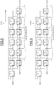
- the signal SH2 controls flip-flops D referenced Dff which will enter the counting result at each edge of the signal SH2.
- the structure of the counter CNT2 is identical to that of the counter CNT1. It is this time the SRF signal which controls the D flip-flops referenced Dff which will enter the counting result at each edge of the SRF signal.
- the reference input which receives the SRF signal is the clock input of each Dff flip-flop.
- the output of the counter CNT2 would already by successive differences of the results of the counter, to obtain the frequency ratio mentioned above.
- the figure 6 illustrates an example of a method for determining a frequency of the SSP signal from the reference signal SRF.
- a) of the method counting of a number C i of integer periods of the signal SSP is carried out during a first reference period P 1 of the reference signal SRF.
- step c) a first average M11 of the different numbers C i counted during the four repetitions of the first step a).
- the value of the second average M2 is the frequency ratio FRP / FRF that we have sought to estimate.
- This formula is particularly advantageous because it allows not only to apply the formula with software means, but also with simple hardware.
- the switches are shown here to illustrate functional switching between the different elements. Of course, different ways are possible to perform these switches. It is possible to use transistors or to freeze, for example, the operation of some of these means.
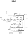
- the switch SW1 connects the output of the adder ADD3 to the input of the loop filter LPF1
- the switch SW3 connects the output of the counter CNT2 to the input of the block BTR and the switch SW2 is open.
- the switch SW1 connects the output of the loop filter LPF2 to the input of the loop filter LPF1
- the switch SW3 connects the output of the counter CNT2 to an input of the adder ADD2 by means of MMF means of frequency measurement and the switch SW2 is closed, connecting the output of the register RG to the other input of the adder ADD2 whose output is connected to the input of the LPF2 loop filter.
- the phase locked loop PLL allows servocontrol of the output signal SSP of the oscillator OSCP on the phase and the frequency of the signal SH2.
- the estimation of the frequency ratio between the FRP frequency of the SSP signal and the FRF reference frequency of the reference signal SRF is carried out, in the example described here by means of sliding measurements within the block. BTR treatment.
- the first servocontrol means always comprise a phase locked loop PLL comprising the main oscillator OSCP, a loop filter LPF1, and the counter CNT1.
- the output of the LPF2 loop filter is connected to the input of the ADF adaptive filter via another switch SW8 and another adder ADD4.
- the adder ADD4 can be short-circuited by the switches SW6 and SW5 so as to freeze the content of the ADF adaptive filter and directly connect the LPF2 loop filter to the input of the main oscillator OSCP.
- the SSP signal of the oscillator OSCP is phase and frequency controlled by the PLL phase-locked loop on the signal SH2 and since the two loop filters LPF1 and LPF2 have the same cut-off frequency and the response of the frequency locked loop is identical to that of the loop to phase lock, the frequency ratio FRP / FRF between the frequency of the SSP signal and the frequency of the SRF signal is determined by the ADF adaptive filter, the output of this ADF filter acting as a set word for the frequency locked loop .
- the control means disconnects the main oscillator OSCP from the loop filter LPF1 so as to deactivate the phase-locked loop and the output of the adaptive filter is frozen and connected to the frequency-locked loop FLL so as to slave only in frequency the output signal of the main oscillator on the frequency of the reference signal corrected by the output word of the adaptive filter which again acts as a target word for the frequency locked loop FLL.
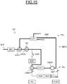
- the first servocontrol means always comprise the PLL phase locked loop which include the main oscillator OSCP
- the estimation means also comprise a frequency locked loop FLL having a reference input for receiving the SRF reference signal.
- this reference input is the clocking input of each flip-flop Dff of the counter CNT2, a counter whose output is connected to the means for measuring the frequency MMF.
- the frequency-locked loop comprises an LPF2 loop filter as well as a WWF stabilizing integrating filter connected to the input of the loop filter via an adder ADD5 which also receives the output of the MMF frequency measuring means. incorporating the CNT2 counter.
- the output of the adder ADD3 can be disconnected from the input of the integrating filter WWF stabilizer via a switch SW7 controllable by the control means MC.
- the control of the SSP output signal of the main oscillator OSCP during this calibration phase is carried out within the PLL phase-locked loop and the estimation of the frequency ratio is carried out by the complete system (locking loop PLL phase and frequency locked loop FLL) from the WWF stabilizing integrator filter whose output forms a set word for the frequency locked loop. More precisely, the phase-locked loop makes the system converge towards the right frequency ratio.
- the frequency locked loop is here equivalent to a low-pass filter and an integrator (conversion of the frequency to the phase).
- the phase locked loop adjusts the setpoint word that tends to the FRP / FRF frequency ratio.
- the processing means MT also comprise modulation means configured to apply a modulation on the generated main clock signal.
- phase modulation means MOD2 are configured to apply the phase modulation prior to the delivery of the main clock signal SH1.
- the clock signal SH1 generated is then already modulated in phase.
- the modulation means are configured to inject phase modulation at two points on either side of the loop filter (s) of the phase-locked loop and / or the frequency-locked loop. .
- the PSK phase modulation is derived to be expressed in frequency (Fmod) in order to be homogeneous with the measured word corresponding to the FRP / FRF frequency ratio.
- the integration function of the oscillator OSCP allows the return to the phase and the addition of Fmod at the input of the oscillator OSCP is corrected for the gain Koscp of the oscillator for the modulation.
Landscapes
- Engineering & Computer Science (AREA)
- Computer Networks & Wireless Communication (AREA)
- Signal Processing (AREA)
- Physics & Mathematics (AREA)
- Health & Medical Sciences (AREA)
- Toxicology (AREA)
- Computer Security & Cryptography (AREA)
- Electromagnetism (AREA)
- General Health & Medical Sciences (AREA)
- Artificial Intelligence (AREA)
- Computer Vision & Pattern Recognition (AREA)
- General Physics & Mathematics (AREA)
- Theoretical Computer Science (AREA)
- Stabilization Of Oscillater, Synchronisation, Frequency Synthesizers (AREA)
Applications Claiming Priority (1)
| Application Number | Priority Date | Filing Date | Title |
|---|---|---|---|
| FR1657226A FR3054760A1 (fr) | 2016-07-27 | 2016-07-27 | Procede de communication sans contact entre un objet, par exemple un telephone mobile emule en mode carte, et un lecteur par modulation active de charge |
Publications (2)
| Publication Number | Publication Date |
|---|---|
| EP3276986A1 true EP3276986A1 (de) | 2018-01-31 |
| EP3276986B1 EP3276986B1 (de) | 2020-10-07 |
Family
ID=56920850
Family Applications (1)
| Application Number | Title | Priority Date | Filing Date |
|---|---|---|---|
| EP17156586.4A Active EP3276986B1 (de) | 2016-07-27 | 2017-02-17 | Kontaktloses kommunikationsverfahren zwischen einem objekt, beispielsweise einem im kartenmodus emulierten mobiltelefon, und einem lesegerät durch aktive lastmodulation |
Country Status (4)
| Country | Link |
|---|---|
| US (1) | US9998178B2 (de) |
| EP (1) | EP3276986B1 (de) |
| CN (2) | CN107666337B (de) |
| FR (1) | FR3054760A1 (de) |
Cited By (3)
| Publication number | Priority date | Publication date | Assignee | Title |
|---|---|---|---|---|
| FR3077174A1 (fr) * | 2018-01-19 | 2019-07-26 | Stmicroelectronics Sa | Synchronisation entre un lecteur et un objet communiquant sans contact avec le lecteur par modulation active de charge |
| FR3080476A1 (fr) * | 2018-04-24 | 2019-10-25 | Stmicroelectronics (Rousset) Sas | Procede de reglage de la phase du signal emis par un objet capable de communiquer sans contact avec un lecteur par modulation active de charge, et objet correspondant |
| FR3086476A1 (fr) * | 2018-09-25 | 2020-03-27 | Stmicroelectronics Sa | Synchronisation rapide entre un objet et un lecteur communiquant sans contact par une modulation active de charge |
Families Citing this family (9)
| Publication number | Priority date | Publication date | Assignee | Title |
|---|---|---|---|---|
| FR3054760A1 (fr) * | 2016-07-27 | 2018-02-02 | Stmicroelectronics Sa | Procede de communication sans contact entre un objet, par exemple un telephone mobile emule en mode carte, et un lecteur par modulation active de charge |
| US10511347B2 (en) * | 2017-11-14 | 2019-12-17 | Nxp B.V. | Device detection in contactless communication systems |
| FR3076972A1 (fr) * | 2018-01-15 | 2019-07-19 | Stmicroelectronics (Grenoble 2) Sas | Procede de synchronisation de signaux au sein d'un dispositif sans contact communiquant avec un lecteur par une modulation active de charge, et dispositif correspondant |
| US10886929B2 (en) * | 2018-05-31 | 2021-01-05 | Wiliot, LTD. | Oscillator calibration from over-the-air signals for low power frequency/time references wireless radios |
| KR102644945B1 (ko) | 2018-12-14 | 2024-03-08 | 삼성전자주식회사 | 클럭 주파수 공급 장치 및 방법 |
| FR3095912B1 (fr) * | 2019-05-06 | 2022-05-13 | St Microelectronics Rousset | Procédé de compensation d’un déphasage entre le signal émis par un objet et celui reçu d’un lecteur équipé d’un détecteur d’enveloppe et objet correspondant |
| FR3102625B1 (fr) * | 2019-10-28 | 2021-11-12 | St Microelectronics Sa | Dispositif NFC émulé en mode carte comprenant une boucle à verrouillage de phase numérique, et procédé de communication correspondant. |
| FR3116168B1 (fr) | 2020-11-12 | 2023-05-12 | St Microelectronics Rousset | Calibration d’une durée d’activation d’un circuit |
| FR3133508B1 (fr) | 2022-03-11 | 2024-03-15 | St Microelectronics Grenoble 2 | Dispositif comportant un circuit de synchronisation pour realiser une communication en champ proche |
Citations (5)
| Publication number | Priority date | Publication date | Assignee | Title |
|---|---|---|---|---|
| FR1561153A (de) | 1967-01-04 | 1969-03-28 | ||
| EP2431926A1 (de) * | 2010-09-21 | 2012-03-21 | Inside Secure | NFC Karte für ein tragbares Gerät |
| EP2680457A2 (de) * | 2012-06-28 | 2014-01-01 | Broadcom Corporation | NFC-Vorrichtung mit PLL-gesteuerter aktiver Lastmodulation |
| EP2843840A1 (de) * | 2013-08-30 | 2015-03-04 | Nxp B.V. | Taktsynchronisiereinrichtung zum Ausrichten von Fernvorrichtungen |
| US20160142113A1 (en) * | 2014-11-19 | 2016-05-19 | Qualcomm Incorporated | Systems and methods for inductively coupled communications |
Family Cites Families (8)
| Publication number | Priority date | Publication date | Assignee | Title |
|---|---|---|---|---|
| US5917351A (en) * | 1997-08-21 | 1999-06-29 | National Science Council | Relay-race FLL/PLL high-speed timing acquisition device |
| JP5290589B2 (ja) * | 2008-02-06 | 2013-09-18 | ルネサスエレクトロニクス株式会社 | 半導体集積回路 |
| US7884676B1 (en) * | 2009-08-03 | 2011-02-08 | Panasonic Corporation | PLL/FLL circuit with gain control |
| FR2965082B1 (fr) * | 2010-09-21 | 2012-09-28 | Inside Contactless | Procede et dispositif de modulation de charge active par couplage inductif |
| EP2490389B1 (de) * | 2011-02-18 | 2015-10-21 | Alcatel Lucent | Vorrichtung, Verfahren und Computerprogramm zur Bestimmung eines Frequenzversatzes |
| EP2988427B1 (de) * | 2014-08-22 | 2019-04-24 | STMicroelectronics International N.V. | Verfahren für eine Phasenkalibrierung in einer Frontendschaltung einer Nahfeldkommunikation, NFC, Etikettierungsvorrichtung, Frontendschaltung einer NFC-Etikettierungsvorrichtung |
| US9553747B2 (en) * | 2014-12-23 | 2017-01-24 | Qualcomm Incorporated | Systems and methods for switching quality factors during inductively coupled communications |
| FR3054760A1 (fr) * | 2016-07-27 | 2018-02-02 | Stmicroelectronics Sa | Procede de communication sans contact entre un objet, par exemple un telephone mobile emule en mode carte, et un lecteur par modulation active de charge |
-
2016
- 2016-07-27 FR FR1657226A patent/FR3054760A1/fr active Pending
-
2017
- 2017-02-17 EP EP17156586.4A patent/EP3276986B1/de active Active
- 2017-02-19 US US15/436,826 patent/US9998178B2/en active Active
- 2017-03-17 CN CN201710161849.0A patent/CN107666337B/zh active Active
- 2017-03-17 CN CN201720263493.7U patent/CN206820749U/zh not_active Withdrawn - After Issue
Patent Citations (5)
| Publication number | Priority date | Publication date | Assignee | Title |
|---|---|---|---|---|
| FR1561153A (de) | 1967-01-04 | 1969-03-28 | ||
| EP2431926A1 (de) * | 2010-09-21 | 2012-03-21 | Inside Secure | NFC Karte für ein tragbares Gerät |
| EP2680457A2 (de) * | 2012-06-28 | 2014-01-01 | Broadcom Corporation | NFC-Vorrichtung mit PLL-gesteuerter aktiver Lastmodulation |
| EP2843840A1 (de) * | 2013-08-30 | 2015-03-04 | Nxp B.V. | Taktsynchronisiereinrichtung zum Ausrichten von Fernvorrichtungen |
| US20160142113A1 (en) * | 2014-11-19 | 2016-05-19 | Qualcomm Incorporated | Systems and methods for inductively coupled communications |
Non-Patent Citations (1)
| Title |
|---|
| MICHAEL GEBHART ET AL: "Active load modulation for contactless near-field communication", RFID-TECHNOLOGIES AND APPLICATIONS (RFID-TA), 2012 IEEE INTERNATIONAL CONFERENCE ON, IEEE, 5 November 2012 (2012-11-05), pages 228 - 233, XP032299612, ISBN: 978-1-4673-4656-6, DOI: 10.1109/RFID-TA.2012.6404518 * |
Cited By (8)
| Publication number | Priority date | Publication date | Assignee | Title |
|---|---|---|---|---|
| FR3077174A1 (fr) * | 2018-01-19 | 2019-07-26 | Stmicroelectronics Sa | Synchronisation entre un lecteur et un objet communiquant sans contact avec le lecteur par modulation active de charge |
| US10841887B2 (en) | 2018-01-19 | 2020-11-17 | Stmicroelectronics Sa | Synchronization between a reader and an object in contactless communication with the reader by active load modulation |
| FR3080476A1 (fr) * | 2018-04-24 | 2019-10-25 | Stmicroelectronics (Rousset) Sas | Procede de reglage de la phase du signal emis par un objet capable de communiquer sans contact avec un lecteur par modulation active de charge, et objet correspondant |
| EP3561730A1 (de) * | 2018-04-24 | 2019-10-30 | STMicroelectronics (Rousset) SAS | Regulierungsverfahren der phase des signals, das von einem objekt abgegeben wird, das durch aktive modulierung der ladung kontaktlos mit einem lesegerät kommunizieren kann, und entsprechendes objekt |
| US11126805B2 (en) | 2018-04-24 | 2021-09-21 | Stmicroelectronics (Rousset) Sas | Method for adjusting phase in contactless communication |
| FR3086476A1 (fr) * | 2018-09-25 | 2020-03-27 | Stmicroelectronics Sa | Synchronisation rapide entre un objet et un lecteur communiquant sans contact par une modulation active de charge |
| EP3629487A1 (de) * | 2018-09-25 | 2020-04-01 | Stmicroelectronics Sa | Schnellsynchronisierung zwischen einem objekt und einem lesegerät, die kontaktlos über eine aktive modulation der ladung kommunizieren |
| US10749719B2 (en) | 2018-09-25 | 2020-08-18 | Stmicroelectronics S.A. | Synchronization between an object and a reader contactlessly communicating by active load modulation |
Also Published As
| Publication number | Publication date |
|---|---|
| CN107666337B (zh) | 2021-07-16 |
| EP3276986B1 (de) | 2020-10-07 |
| CN206820749U (zh) | 2017-12-29 |
| CN107666337A (zh) | 2018-02-06 |
| US9998178B2 (en) | 2018-06-12 |
| FR3054760A1 (fr) | 2018-02-02 |
| US20180034505A1 (en) | 2018-02-01 |
Similar Documents
| Publication | Publication Date | Title |
|---|---|---|
| EP3276986B1 (de) | Kontaktloses kommunikationsverfahren zwischen einem objekt, beispielsweise einem im kartenmodus emulierten mobiltelefon, und einem lesegerät durch aktive lastmodulation | |
| EP3629487B1 (de) | Schnellsynchronisierung zwischen einem objekt und einem lesegerät, die kontaktlos über eine aktive modulation der ladung kommunizieren | |
| FR3077174A1 (fr) | Synchronisation entre un lecteur et un objet communiquant sans contact avec le lecteur par modulation active de charge | |
| EP2230774B1 (de) | Verfahren zur Herstellung einer Datenverbindung zwischen zwei Prozessoren, insbesondere in einem NFC-Chipset | |
| WO2012150388A1 (fr) | Procede et dispositif de modulation en amplitude d'un signal electromagnetique emis par un systeme d'emission/reception sans contact | |
| EP3871385B1 (de) | Übertragungsverfahren für pilotsymbole | |
| FR3026583A1 (fr) | Procede de gestion du fonctionnement d'un objet capable de communiquer sans contact avec un lecteur, dispositif et objet correspondants | |
| EP2706660A1 (de) | Vorrichtung zum Senden von Datensignalen und/oder Steuern mit Antennenanordnungen | |
| EP3736995B1 (de) | Kompensationsverafhren einer phasenverschiebung zwischen einem von einem gegenstand ausgesendeten signal und dem von einem mit einem hüllkurvendetektor ausgestatteten lesegerät empfangenen signal, und entsprechender gegenstand | |
| FR3133508A1 (fr) | Dispositif comportant un circuit de synchronisation pour realiser une communication en champ proche | |
| EP2428011A1 (de) | Demodulator und system zum übertragen von modulierten informationen insbesondere für hochfrequenzidentifikationsetiketten | |
| EP2999130B1 (de) | Kontaktloses kommunikationsverfahren zwischen zwei nfc-geräten mit reduzierung des einflusses einer externen lärmemission | |
| FR3102625A1 (fr) | Dispositif NFC émulé en mode carte comprenant une boucle à verrouillage de phase numérique, et procédé de communication correspondant. | |
| EP4529028B1 (de) | Kontaktlose lastmodulationskommunikationsvorrichtung mit dynamischer schwellwert-taktsignalextraktionsschaltung | |
| FR3153487A1 (fr) | Dispositif de communication sans contact par modulation active de charge | |
| FR3153488A1 (fr) | Dispositif de communication sans contact par modulation active de charge | |
| EP4016856A1 (de) | Verfahren zur rückmodulation einer kontaktlosen kommunikation und entsprechender transponder | |
| EP2586166B1 (de) | Phasenmodulationsverfahren eines trägersignals von einem sender zu einem kontaktlosen transponder und dessen implementierungseinrichtung | |
| EP4451574A1 (de) | Drahtloses kommunikations- und ladegerät | |
| FR3159867A1 (fr) | Contrôleur NFC | |
| EP2009790A1 (de) | Abstimmungsmethode der Resonanzfrequenz einer Antenne | |
| FR2837929A1 (fr) | Dispositif d'emission et de reception de signaux pour l'etude de materiaux par resonance magnetique nucleaire | |
| FR3039944A1 (fr) | Dispositif de communication radiofrequence actif |
Legal Events
| Date | Code | Title | Description |
|---|---|---|---|
| PUAI | Public reference made under article 153(3) epc to a published international application that has entered the european phase |
Free format text: ORIGINAL CODE: 0009012 |
|
| STAA | Information on the status of an ep patent application or granted ep patent |
Free format text: STATUS: REQUEST FOR EXAMINATION WAS MADE |
|
| 17P | Request for examination filed |
Effective date: 20170217 |
|
| AK | Designated contracting states |
Kind code of ref document: A1 Designated state(s): AL AT BE BG CH CY CZ DE DK EE ES FI FR GB GR HR HU IE IS IT LI LT LU LV MC MK MT NL NO PL PT RO RS SE SI SK SM TR |
|
| AX | Request for extension of the european patent |
Extension state: BA ME |
|
| STAA | Information on the status of an ep patent application or granted ep patent |
Free format text: STATUS: EXAMINATION IS IN PROGRESS |
|
| 17Q | First examination report despatched |
Effective date: 20191104 |
|
| REG | Reference to a national code |
Ref country code: DE Ref legal event code: R079 Ref document number: 602017024843 Country of ref document: DE Free format text: PREVIOUS MAIN CLASS: H04W0004000000 Ipc: H03L0007080000 |
|
| RIC1 | Information provided on ipc code assigned before grant |
Ipc: H04W 4/00 20180101ALI20200312BHEP Ipc: H03L 7/099 20060101ALI20200312BHEP Ipc: H04B 5/00 20060101ALI20200312BHEP Ipc: H04W 4/80 20180101ALI20200312BHEP Ipc: H03L 7/08 20060101AFI20200312BHEP Ipc: H03L 7/23 20060101ALI20200312BHEP Ipc: H03L 7/14 20060101ALI20200312BHEP |
|
| GRAP | Despatch of communication of intention to grant a patent |
Free format text: ORIGINAL CODE: EPIDOSNIGR1 |
|
| STAA | Information on the status of an ep patent application or granted ep patent |
Free format text: STATUS: GRANT OF PATENT IS INTENDED |
|
| INTG | Intention to grant announced |
Effective date: 20200504 |
|
| GRAS | Grant fee paid |
Free format text: ORIGINAL CODE: EPIDOSNIGR3 |
|
| GRAA | (expected) grant |
Free format text: ORIGINAL CODE: 0009210 |
|
| STAA | Information on the status of an ep patent application or granted ep patent |
Free format text: STATUS: THE PATENT HAS BEEN GRANTED |
|
| AK | Designated contracting states |
Kind code of ref document: B1 Designated state(s): AL AT BE BG CH CY CZ DE DK EE ES FI FR GB GR HR HU IE IS IT LI LT LU LV MC MK MT NL NO PL PT RO RS SE SI SK SM TR |
|
| REG | Reference to a national code |
Ref country code: GB Ref legal event code: FG4D Free format text: NOT ENGLISH |
|
| REG | Reference to a national code |
Ref country code: AT Ref legal event code: REF Ref document number: 1322262 Country of ref document: AT Kind code of ref document: T Effective date: 20201015 Ref country code: CH Ref legal event code: EP |
|
| REG | Reference to a national code |
Ref country code: DE Ref legal event code: R096 Ref document number: 602017024843 Country of ref document: DE |
|
| REG | Reference to a national code |
Ref country code: IE Ref legal event code: FG4D Free format text: LANGUAGE OF EP DOCUMENT: FRENCH |
|
| REG | Reference to a national code |
Ref country code: NL Ref legal event code: MP Effective date: 20201007 |
|
| REG | Reference to a national code |
Ref country code: AT Ref legal event code: MK05 Ref document number: 1322262 Country of ref document: AT Kind code of ref document: T Effective date: 20201007 |
|
| PG25 | Lapsed in a contracting state [announced via postgrant information from national office to epo] |
Ref country code: GR Free format text: LAPSE BECAUSE OF FAILURE TO SUBMIT A TRANSLATION OF THE DESCRIPTION OR TO PAY THE FEE WITHIN THE PRESCRIBED TIME-LIMIT Effective date: 20210108 Ref country code: FI Free format text: LAPSE BECAUSE OF FAILURE TO SUBMIT A TRANSLATION OF THE DESCRIPTION OR TO PAY THE FEE WITHIN THE PRESCRIBED TIME-LIMIT Effective date: 20201007 Ref country code: NO Free format text: LAPSE BECAUSE OF FAILURE TO SUBMIT A TRANSLATION OF THE DESCRIPTION OR TO PAY THE FEE WITHIN THE PRESCRIBED TIME-LIMIT Effective date: 20210107 Ref country code: NL Free format text: LAPSE BECAUSE OF FAILURE TO SUBMIT A TRANSLATION OF THE DESCRIPTION OR TO PAY THE FEE WITHIN THE PRESCRIBED TIME-LIMIT Effective date: 20201007 Ref country code: RS Free format text: LAPSE BECAUSE OF FAILURE TO SUBMIT A TRANSLATION OF THE DESCRIPTION OR TO PAY THE FEE WITHIN THE PRESCRIBED TIME-LIMIT Effective date: 20201007 Ref country code: PT Free format text: LAPSE BECAUSE OF FAILURE TO SUBMIT A TRANSLATION OF THE DESCRIPTION OR TO PAY THE FEE WITHIN THE PRESCRIBED TIME-LIMIT Effective date: 20210208 |
|
| REG | Reference to a national code |
Ref country code: LT Ref legal event code: MG4D |
|
| PG25 | Lapsed in a contracting state [announced via postgrant information from national office to epo] |
Ref country code: SE Free format text: LAPSE BECAUSE OF FAILURE TO SUBMIT A TRANSLATION OF THE DESCRIPTION OR TO PAY THE FEE WITHIN THE PRESCRIBED TIME-LIMIT Effective date: 20201007 Ref country code: ES Free format text: LAPSE BECAUSE OF FAILURE TO SUBMIT A TRANSLATION OF THE DESCRIPTION OR TO PAY THE FEE WITHIN THE PRESCRIBED TIME-LIMIT Effective date: 20201007 Ref country code: AT Free format text: LAPSE BECAUSE OF FAILURE TO SUBMIT A TRANSLATION OF THE DESCRIPTION OR TO PAY THE FEE WITHIN THE PRESCRIBED TIME-LIMIT Effective date: 20201007 Ref country code: BG Free format text: LAPSE BECAUSE OF FAILURE TO SUBMIT A TRANSLATION OF THE DESCRIPTION OR TO PAY THE FEE WITHIN THE PRESCRIBED TIME-LIMIT Effective date: 20210107 Ref country code: IS Free format text: LAPSE BECAUSE OF FAILURE TO SUBMIT A TRANSLATION OF THE DESCRIPTION OR TO PAY THE FEE WITHIN THE PRESCRIBED TIME-LIMIT Effective date: 20210207 Ref country code: LV Free format text: LAPSE BECAUSE OF FAILURE TO SUBMIT A TRANSLATION OF THE DESCRIPTION OR TO PAY THE FEE WITHIN THE PRESCRIBED TIME-LIMIT Effective date: 20201007 Ref country code: PL Free format text: LAPSE BECAUSE OF FAILURE TO SUBMIT A TRANSLATION OF THE DESCRIPTION OR TO PAY THE FEE WITHIN THE PRESCRIBED TIME-LIMIT Effective date: 20201007 |
|
| PG25 | Lapsed in a contracting state [announced via postgrant information from national office to epo] |
Ref country code: HR Free format text: LAPSE BECAUSE OF FAILURE TO SUBMIT A TRANSLATION OF THE DESCRIPTION OR TO PAY THE FEE WITHIN THE PRESCRIBED TIME-LIMIT Effective date: 20201007 |
|
| REG | Reference to a national code |
Ref country code: DE Ref legal event code: R097 Ref document number: 602017024843 Country of ref document: DE |
|
| PG25 | Lapsed in a contracting state [announced via postgrant information from national office to epo] |
Ref country code: LT Free format text: LAPSE BECAUSE OF FAILURE TO SUBMIT A TRANSLATION OF THE DESCRIPTION OR TO PAY THE FEE WITHIN THE PRESCRIBED TIME-LIMIT Effective date: 20201007 Ref country code: SM Free format text: LAPSE BECAUSE OF FAILURE TO SUBMIT A TRANSLATION OF THE DESCRIPTION OR TO PAY THE FEE WITHIN THE PRESCRIBED TIME-LIMIT Effective date: 20201007 Ref country code: CZ Free format text: LAPSE BECAUSE OF FAILURE TO SUBMIT A TRANSLATION OF THE DESCRIPTION OR TO PAY THE FEE WITHIN THE PRESCRIBED TIME-LIMIT Effective date: 20201007 Ref country code: EE Free format text: LAPSE BECAUSE OF FAILURE TO SUBMIT A TRANSLATION OF THE DESCRIPTION OR TO PAY THE FEE WITHIN THE PRESCRIBED TIME-LIMIT Effective date: 20201007 Ref country code: RO Free format text: LAPSE BECAUSE OF FAILURE TO SUBMIT A TRANSLATION OF THE DESCRIPTION OR TO PAY THE FEE WITHIN THE PRESCRIBED TIME-LIMIT Effective date: 20201007 Ref country code: SK Free format text: LAPSE BECAUSE OF FAILURE TO SUBMIT A TRANSLATION OF THE DESCRIPTION OR TO PAY THE FEE WITHIN THE PRESCRIBED TIME-LIMIT Effective date: 20201007 |
|
| PLBE | No opposition filed within time limit |
Free format text: ORIGINAL CODE: 0009261 |
|
| STAA | Information on the status of an ep patent application or granted ep patent |
Free format text: STATUS: NO OPPOSITION FILED WITHIN TIME LIMIT |
|
| PG25 | Lapsed in a contracting state [announced via postgrant information from national office to epo] |
Ref country code: DK Free format text: LAPSE BECAUSE OF FAILURE TO SUBMIT A TRANSLATION OF THE DESCRIPTION OR TO PAY THE FEE WITHIN THE PRESCRIBED TIME-LIMIT Effective date: 20201007 |
|
| 26N | No opposition filed |
Effective date: 20210708 |
|
| PG25 | Lapsed in a contracting state [announced via postgrant information from national office to epo] |
Ref country code: MC Free format text: LAPSE BECAUSE OF FAILURE TO SUBMIT A TRANSLATION OF THE DESCRIPTION OR TO PAY THE FEE WITHIN THE PRESCRIBED TIME-LIMIT Effective date: 20201007 |
|
| GBPC | Gb: european patent ceased through non-payment of renewal fee |
Effective date: 20210217 |
|
| REG | Reference to a national code |
Ref country code: BE Ref legal event code: MM Effective date: 20210228 |
|
| PG25 | Lapsed in a contracting state [announced via postgrant information from national office to epo] |
Ref country code: IT Free format text: LAPSE BECAUSE OF FAILURE TO SUBMIT A TRANSLATION OF THE DESCRIPTION OR TO PAY THE FEE WITHIN THE PRESCRIBED TIME-LIMIT Effective date: 20201007 Ref country code: LU Free format text: LAPSE BECAUSE OF NON-PAYMENT OF DUE FEES Effective date: 20210217 Ref country code: LI Free format text: LAPSE BECAUSE OF NON-PAYMENT OF DUE FEES Effective date: 20210228 Ref country code: AL Free format text: LAPSE BECAUSE OF FAILURE TO SUBMIT A TRANSLATION OF THE DESCRIPTION OR TO PAY THE FEE WITHIN THE PRESCRIBED TIME-LIMIT Effective date: 20201007 Ref country code: CH Free format text: LAPSE BECAUSE OF NON-PAYMENT OF DUE FEES Effective date: 20210228 |
|
| PG25 | Lapsed in a contracting state [announced via postgrant information from national office to epo] |
Ref country code: SI Free format text: LAPSE BECAUSE OF FAILURE TO SUBMIT A TRANSLATION OF THE DESCRIPTION OR TO PAY THE FEE WITHIN THE PRESCRIBED TIME-LIMIT Effective date: 20201007 |
|
| PG25 | Lapsed in a contracting state [announced via postgrant information from national office to epo] |
Ref country code: IE Free format text: LAPSE BECAUSE OF NON-PAYMENT OF DUE FEES Effective date: 20210217 Ref country code: GB Free format text: LAPSE BECAUSE OF NON-PAYMENT OF DUE FEES Effective date: 20210217 Ref country code: FR Free format text: LAPSE BECAUSE OF NON-PAYMENT OF DUE FEES Effective date: 20210228 |
|
| PG25 | Lapsed in a contracting state [announced via postgrant information from national office to epo] |
Ref country code: IS Free format text: LAPSE BECAUSE OF FAILURE TO SUBMIT A TRANSLATION OF THE DESCRIPTION OR TO PAY THE FEE WITHIN THE PRESCRIBED TIME-LIMIT Effective date: 20210207 |
|
| PG25 | Lapsed in a contracting state [announced via postgrant information from national office to epo] |
Ref country code: BE Free format text: LAPSE BECAUSE OF NON-PAYMENT OF DUE FEES Effective date: 20210228 |
|
| PG25 | Lapsed in a contracting state [announced via postgrant information from national office to epo] |
Ref country code: CY Free format text: LAPSE BECAUSE OF FAILURE TO SUBMIT A TRANSLATION OF THE DESCRIPTION OR TO PAY THE FEE WITHIN THE PRESCRIBED TIME-LIMIT Effective date: 20201007 |
|
| PG25 | Lapsed in a contracting state [announced via postgrant information from national office to epo] |
Ref country code: HU Free format text: LAPSE BECAUSE OF FAILURE TO SUBMIT A TRANSLATION OF THE DESCRIPTION OR TO PAY THE FEE WITHIN THE PRESCRIBED TIME-LIMIT; INVALID AB INITIO Effective date: 20170217 |
|
| PG25 | Lapsed in a contracting state [announced via postgrant information from national office to epo] |
Ref country code: MK Free format text: LAPSE BECAUSE OF FAILURE TO SUBMIT A TRANSLATION OF THE DESCRIPTION OR TO PAY THE FEE WITHIN THE PRESCRIBED TIME-LIMIT Effective date: 20201007 |
|
| PG25 | Lapsed in a contracting state [announced via postgrant information from national office to epo] |
Ref country code: MT Free format text: LAPSE BECAUSE OF FAILURE TO SUBMIT A TRANSLATION OF THE DESCRIPTION OR TO PAY THE FEE WITHIN THE PRESCRIBED TIME-LIMIT Effective date: 20201007 |
|
| REG | Reference to a national code |
Ref country code: DE Ref legal event code: R081 Ref document number: 602017024843 Country of ref document: DE Owner name: STMICROELECTRONICS FRANCE, FR Free format text: FORMER OWNER: STMICROELECTRONICS SA, MONTROUGE, FR |
|
| PG25 | Lapsed in a contracting state [announced via postgrant information from national office to epo] |
Ref country code: TR Free format text: LAPSE BECAUSE OF FAILURE TO SUBMIT A TRANSLATION OF THE DESCRIPTION OR TO PAY THE FEE WITHIN THE PRESCRIBED TIME-LIMIT Effective date: 20201007 |
|
| PGFP | Annual fee paid to national office [announced via postgrant information from national office to epo] |
Ref country code: DE Payment date: 20260121 Year of fee payment: 10 |