EP3277237B1 - Interpositionelles ophthalmologisches implantat - Google Patents
Interpositionelles ophthalmologisches implantat Download PDFInfo
- Publication number
- EP3277237B1 EP3277237B1 EP16719446.3A EP16719446A EP3277237B1 EP 3277237 B1 EP3277237 B1 EP 3277237B1 EP 16719446 A EP16719446 A EP 16719446A EP 3277237 B1 EP3277237 B1 EP 3277237B1
- Authority
- EP
- European Patent Office
- Prior art keywords
- implant
- thickness
- interpositional
- ophthalmological
- dimensions
- Prior art date
- Legal status (The legal status is an assumption and is not a legal conclusion. Google has not performed a legal analysis and makes no representation as to the accuracy of the status listed.)
- Active
Links
Images


Classifications
-
- A—HUMAN NECESSITIES
- A61—MEDICAL OR VETERINARY SCIENCE; HYGIENE
- A61F—FILTERS IMPLANTABLE INTO BLOOD VESSELS; PROSTHESES; DEVICES PROVIDING PATENCY TO, OR PREVENTING COLLAPSING OF, TUBULAR STRUCTURES OF THE BODY, e.g. STENTS; ORTHOPAEDIC, NURSING OR CONTRACEPTIVE DEVICES; FOMENTATION; TREATMENT OR PROTECTION OF EYES OR EARS; BANDAGES, DRESSINGS OR ABSORBENT PADS; FIRST-AID KITS
- A61F9/00—Methods or devices for treatment of the eyes; Devices for putting in contact-lenses; Devices to correct squinting; Apparatus to guide the blind; Protective devices for the eyes, carried on the body or in the hand
- A61F9/0008—Introducing ophthalmic products into the ocular cavity or retaining products therein
- A61F9/0017—Introducing ophthalmic products into the ocular cavity or retaining products therein implantable in, or in contact with, the eye, e.g. ocular inserts
-
- A—HUMAN NECESSITIES
- A61—MEDICAL OR VETERINARY SCIENCE; HYGIENE
- A61F—FILTERS IMPLANTABLE INTO BLOOD VESSELS; PROSTHESES; DEVICES PROVIDING PATENCY TO, OR PREVENTING COLLAPSING OF, TUBULAR STRUCTURES OF THE BODY, e.g. STENTS; ORTHOPAEDIC, NURSING OR CONTRACEPTIVE DEVICES; FOMENTATION; TREATMENT OR PROTECTION OF EYES OR EARS; BANDAGES, DRESSINGS OR ABSORBENT PADS; FIRST-AID KITS
- A61F9/00—Methods or devices for treatment of the eyes; Devices for putting in contact-lenses; Devices to correct squinting; Apparatus to guide the blind; Protective devices for the eyes, carried on the body or in the hand
- A61F9/007—Methods or devices for eye surgery
- A61F9/00781—Apparatus for modifying intraocular pressure, e.g. for glaucoma treatment
-
- A—HUMAN NECESSITIES
- A61—MEDICAL OR VETERINARY SCIENCE; HYGIENE
- A61F—FILTERS IMPLANTABLE INTO BLOOD VESSELS; PROSTHESES; DEVICES PROVIDING PATENCY TO, OR PREVENTING COLLAPSING OF, TUBULAR STRUCTURES OF THE BODY, e.g. STENTS; ORTHOPAEDIC, NURSING OR CONTRACEPTIVE DEVICES; FOMENTATION; TREATMENT OR PROTECTION OF EYES OR EARS; BANDAGES, DRESSINGS OR ABSORBENT PADS; FIRST-AID KITS
- A61F2250/00—Special features of prostheses classified in groups A61F2/00 - A61F2/26 or A61F2/82 or A61F9/00 or A61F11/00 or subgroups thereof
- A61F2250/0004—Special features of prostheses classified in groups A61F2/00 - A61F2/26 or A61F2/82 or A61F9/00 or A61F11/00 or subgroups thereof adjustable
- A61F2250/0009—Special features of prostheses classified in groups A61F2/00 - A61F2/26 or A61F2/82 or A61F9/00 or A61F11/00 or subgroups thereof adjustable for adjusting thickness
Definitions
- the invention relates to an ophthalmic interposition implant intended to keep the sclera and the ciliary body permanently separated from each other in order to lower intraocular pressure (IOP).
- IOP intraocular pressure
- Intraocular pressure results from a balance between its secretion by the ciliary body and its flow through the meshwork of the corneoscleral trabecular meshwork via Schlemm's canal and its emunctories to the aqueous veins and the general circulation.
- a fraction representing 10 to 15% of this flow occurs directly through the ciliary trabecular meshwork between the sclera and the ciliary body; this is called uveoscleral flow.
- the longitudinal fibers of the ciliary muscle particularly during accommodation, play a role in tensioning the trabecular meshwork, which facilitates the uveoscleral flow of aqueous humor.
- Filtering surgery is the most frequently used and seeks to divert the aqueous humor under the conjunctiva to obtain the necessary pressure reduction. It can create a permanent full-thickness orifice in the trabecular meshwork under a scleral flap: trabeculectomy. It can also leave the internal part of the trabecular meshwork in place, which is called non-penetrating trabecular meshwork surgery (deep sclerectomy, viscocanalostomy).
- filtering surgery has complications related to insufficient filtration due to fibrosis of the filtration bleb (the filtration bleb is present between the sclera and the conjunctiva, which is raised) or, conversely, related to excessive filtration.
- the IOP reduction achieved by these techniques is often insufficient and temporary. It most often requires the resumption or maintenance of one or more hypotensive medical treatments.
- the present invention proposes to increase and make permanent the hypotensive effect of physiological uveoscleral outflow by interposing, between the sclera and the ciliary body, an implant which does not alter the anatomical structures, with or without added intervention, filtering or otherwise.
- the present invention thus relates to a permanent interposition ophthalmological implant according to claim 1.
- the concave anterior edge of the implant body allows the anterior edge to be positioned as close as possible to the trabeculum and on a circumference, which allows the implant to exert its spacing effect in the best possible location (the concavity of the anterior edge is generally adapted to the radius of the cornea).
- This configuration of the concave anterior edge allows the aqueous humor to be permanently collected as close as possible to the uveoscleral outflow zone.
- Such an implant thus provides a significant gain in increasing physiological uveoscleral outflow.
- the body of the implant may have, in projection in a plane perpendicular to the thickness, an external peripheral contour with convex geometry, with the exception of the portion of the body which includes the concave anterior edge.
- the remaining portion of the body in projection in this plane has a convex geometry, that is to say that each time two points A and B of this remaining portion are taken, the segment AB which connects them is entirely contained in said remaining portion.
- this portion may be delimited, on one side, by the concave anterior edge, on the opposite side, by a straight line internal to the body and which tangents the apex of the concave curvature of the edge and by two opposite edges which are each adjacent to the concave anterior edge and to the tangent straight line), in projection in said plane the remaining portion of the body does not have a hollow or bump, nor a re-entrant angle, nor a re-entrant part.
- the thickness of the body is unique in the sense that the body is not formed of several parts, each with a different thickness, which would give the body a profile with variable thickness (e.g., stepped profile, stepped profile, or crenellated profile).
- the body is formed of a single part in the sense that it is homogeneous and does not have a complex shape (with cutouts, hollows, returns, etc.) with local geometry variations, both along the thickness and perpendicular to the thickness.
- the body presents on each of its opposite faces two by two a flat or generally curved shape with a single curvature, i.e. such a shape with undulations or a sawtooth shape is excluded.
- the body does not generally have a shape with cutouts, especially when viewed in projection in a plane perpendicular to the thickness.
- the overall shape of the body is simple compared to the shapes of prior art implant bodies.
- the implant body according to the invention is different from the implant body of the documents WO 95/35078 (body with two parts of different thickness and with different widths perpendicular to the thickness), US 4,521,210 (cross-shaped body with one branch longer than the others), US 2004/0015140 (spatula-shaped body with an anterior portion of reduced width compared to the rest of the body and with lateral cutouts and an axial posterior cutout for the insertion of an implant placement tool) and US 2004/0092856 (T-shaped body with the two opposite ends of the T bar being thicker than the remaining part of the T).
- the document US-A-2004/254521 describes an ophthalmic implant for permanent interposition between the sclera and the uveal tissue, comprising a uveocompatible body formed from a single part, the body of the implant comprising two opposite edges which are distant from each other along one of the two dimensions perpendicular to the thickness.
- the implant body is intended to separate the sclera and uveal tissue from each other in order to permanently interpose itself between them (creating a permanent space), thus creating an area of least resistance to aqueous humor flow.
- a thin body as defined above provides sufficient separation of the overlying and underlying structures (sclera and uveal tissue) to effectively drain physiological uveoscleral outflow.
- a uveocompatible body is one whose constituent material(s) do not erode or denature the surrounding ocular structures, in this case the uveal structures. Biocompatibility of the body alone is not sufficient for the body to be permanently implanted in the uvea, particularly between the sclera and the uveal tissue.
- the invention relates to an ophthalmic implant which is intended to be permanently implanted between the sclera and the uveal tissue and therefore to be permanently interposed between the latter.
- the implant according to the invention comprises a thin body so that, once interposed between the sclera and the uveal tissue, it does not deform the overlying and underlying tissues in an unacceptable manner.
- An acceptable deformation of the tissues is a deformation which does not alter the function(s) of one and/or the other of these tissues.
- One of the two distant edges is called the anterior edge and presents, in projection in a plane perpendicular to the thickness, a concave curvature turned towards the outside of the body.
- the radius of curvature of the concave edge is, for example, between 5 and 7 mm, which allows this edge to be positioned concentrically with the limbus, and therefore as close as possible to the trabeculum. Concentricity is defined in relation to the center of the cornea (center of the circle) which is not always aligned with the center of the pupil. The radius of curvature is, for example, equal to 5.5 mm.
- the other opposite edge is called the posterior edge and it is not necessarily curved (convexity facing outwards) in a plane perpendicular to the thickness. It can in fact be straight or even adopt a different shape.
- the body of the implant comprises at least one material that is known for its uveocompatibility properties and the body is thus uveocompatible. Such properties provide the body with very low adhesion to ocular tissues. In other words, said at least one material is not likely to alter the overlying and underlying structures as a result of the body coming into contact with these structures and their repeated movements over time.
- the body of the implant may present in projection in a plane perpendicular to the thickness an external peripheral contour with convex geometry with the exception of the portion of the body which comprises the concave anterior edge.
- the remaining portion of the body in projection in this plane has a convex geometry, that is to say that each time we take two points A and B of this remaining portion the segment AB which connects them is entirely contained in said remaining portion.
- this portion can be delimited, on one side, by the concave anterior edge, on the opposite side, by an imaginary straight line internal to the body and which tangents the vertex of the concave curvature of the edge and by two opposite edges which are each adjacent to the concave anterior edge and to the tangent straight line), in projection in said plane the remaining portion of the body does not have any hollow or bump, nor any re-entrant angle, nor any re-entrant part.
- the thickness of the body is unique in the sense that the body is not formed of several parts, each having a different thickness and which would give the body a profile with variable thickness (e.g.: stepped profile, stepped profile or crenellated profile).
- the body has on each of its two-by-two opposite faces a flat or generally curved shape with a single curvature, that is to say that such a shape with undulations or a sawtooth shape is excluded.
- the body does not generally have a shape with cutouts, especially when viewed in projection in a plane perpendicular to the thickness.
- an eye 10 is represented in front view in a very schematic manner by the cornea 12 and the pupil 14 in the center.
- FIG. 1 Three possible embodiments of an ophthalmological implant according to the invention are shown in the implanted position around the cornea according to a projection view in a plane perpendicular to the thickness of the body (plane of the Figure 1 ).
- implants referenced 20, 30 and 40 each have in common a concave anterior edge 22, 32, 42 whose concavity, that is to say the radius of curvature, is adjusted so that said edge can be arranged concentrically to the limbus, namely as close as possible to the trabeculum.
- the posterior edge 34 of the implant 30 is convex (convexity facing the outside of the body; alternatively, the posterior edge may be rectilinear) and the radius of curvature may or may not be identical to that of the concave edge 32.
- the body has two lateral edges 36, 38 adjacent to the anterior and posterior edges and connecting the latter together; the lateral edges 36, 38 converge towards each other going from the posterior edge to the anterior edge to the extent that the anterior edge 32 is shorter than the posterior edge 34.
- the body of the implant 30 has a shape in top view (perpendicular to its thickness) which resembles a trapezoid whose base is concave and the apex convex or an annular segment or portion which extends along a given angular sector.
- the body of the implant 30 has here, in projection in a plane perpendicular to the thickness, an external peripheral contour with convex geometry with the exception of the portion 32a of the body which comprises the concave anterior edge 32.
- the remaining portion 32b of the body in projection in this plane has a convex geometry, that is to say that each time that two points A and B of this remaining portion are taken, the segment AB which connects them is entirely contained in said remaining portion.
- This portion is delimited, on one side, by the concave anterior edge 32, on the opposite side, by a straight line or fictitious axis L internal to the body and which tangents the apex of the concave curvature of the edge (on the side of the convexity of the curvature) and by two opposite edges which are each adjacent to the concave anterior edge and to the straight line or axis tangent L.
- a straight line or fictitious axis L internal to the body and which tangents the apex of the concave curvature of the edge (on the side of the convexity of the curvature) and by two opposite edges which are each adjacent to the concave anterior edge and to the straight line or axis tangent L.
- the lateral edges may be parallel to each other.
- the general shape of the body seen from above may be that of a rectangle with the exception of the concave anterior edge, the posterior edge being able to be rectilinear or convex.
- the convex posterior edge 44 of the implant 40 (convexity facing the outside of the body) directly joins the anterior edge 42, there are no adjacent lateral edges; the body thus has a general crescent moon shape when viewed from above ( Fig. 1 ) and thus has between the two anterior 42 and posterior 44 edges a relatively small dimension compared to the implants 20 and 30 where the two edges are further apart from each other.
- the shape of the implant 40 facilitates its placement through a smaller incision than for the implants 20 and 30, while extending the spacing effect towards the rear (posterior edge).
- the lateral edges of the implant can be arranged radially as for implant 30 (radial edges relative to the center of the fictitious circle relative to which the concave edge of the implant is positioned; the edges are thus convergent towards the center of the circle) or flared as for implant 20.
- the posterior edge should be far enough away from the anterior edge to provide an effective spacing effect.
- the posterior edge is at least 3 mm away from the anterior edge.
- the length of the posterior edge does not exceed the length of the front edge.
- an implant may extend over a larger circumference (or angular sector) around the cornea 12 than what is shown in the Figure 1 .
- the length of the anterior edge is, for example, between 3 and 7 mm. Beyond this length, the implant is more difficult to place (larger incision size, etc.).
- an implant in the general sense of the invention increase in physiological uveoscleral flow
- one or more implants arranged around the cornea one against the other or far from each other.
- the various edges or faces or slices or flanks delimiting the outer surface of the implant and which are adjacent to each other are connected to each other by edges, angles or corners which are rounded.
- the body of the implant does not have any sharp edges.
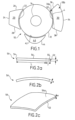
- the body of the implant also has a uniform thickness and, in a three-dimensional view, it has, at rest, a planar shape (the body does not have a second curvature in a direction perpendicular to a plane defined by the two dimensions of the body in a top view as that of the Figure 1 ) or curved (at least a second curvature present in this direction perpendicular to the plane of the two other dimensions).
- FIG. 2a illustrates an implant 50 seen along its thickness noted “e”, that is to say in a direction which is included in the plane of the Figure 1 .
- Such an implant has a concave anterior edge whose concavity is not visible here.
- This implant therefore includes the concave curvature of the anterior edge in a plane defined by the two other dimensions of the body (apart from its thickness) but, at rest (undeformed state), it is flat along a direction perpendicular to this plane (absence of second curvature).
- the body of this implant is made of an elastically deformable material so that it can be bent without inducing permanent deformation to be manipulated with a micro instrument, or injected with an ophthalmic injection system. When such a body is no longer subjected to the bending force, it returns to its original undeformed position (rest).
- FIGS. 2b and 2c illustrate the body of the Figure 2a in a deformed state ( fig.2b : profile view along the thickness; fig.2c : perspective view from above), for example when it has been implanted between the sclera and the uveal tissue.
- This deformed state can also be obtained when an external bending force is imposed on the body by a tool such as a micro instrument or an ophthalmic injection system.
- the body as represented in the Figure 2c fits a portion of a spherical surface and has a general shape of a portion of a spherical cap.
- the shape of the body is therefore particularly adapted to fit a portion of the spherical surface of the ciliary body underlying the implant.
- This body includes the concave anterior edge 52.
- the shape adopted by the body in this deformed state shows that it comprises (in addition to the concave curvature of the anterior edge) a double curvature following a direction perpendicular to the plane defined by the two other dimensions of the body (length and width) illustrated on the Figure 1 .
- On the Figure 2b only one of these other curvatures (in addition to the concave curvature of the anterior edge) is shown.
- the body has two large opposite faces spaced apart from each other along the thickness: a convex upper face 50a which is doubly curved and an opposite lower face not shown which is concave and which is also doubly curved and which is intended to fit a portion of spherical surface.
- This double curvature allows the implant to distribute the spacing effect well between the tissues.
- the convex upper face 50a is intended to be opposite the sclera, while the concave lower face is intended to be opposite the uveal tissue.
- each curvature of the aforementioned double curvature has the same radius of curvature between 10 and 15 mm and, for example, which is equal to 11 mm.
- the body of the implant is made of a material that has a Young's modulus of between 30 and 60 kg/cm2. Such a modulus provides the body with a flexibility characteristic allowing it to deform elastically when placed in the eye and then to be maintained in a permanently deformed state by the structures above and below the eye, following the natural curvatures of these structures. Such a modulus makes it possible not to cause deformations in one and/or other of these structures that would be likely to alter their function(s).
- the Young's modulus is equal to 40 kg/cm2 for an elastically deformable body made from a hydrophilic acrylic material which is, for example, 25% hydrophilic.
- the outline of the body seen in projection on a plane defined by the two largest dimensions as in the Figure 1 (in other words a plane perpendicular to the thickness), may differ from that illustrated on the Figure 2c , except for the front edge 52 which remains concave.
- the front edge may not be thinned as on the Figure 2a .
- flanks or slices of the body that extend along the thickness of the body appear to have sharp edges between adjacent faces, this is not the case. All these edges are rounded regardless of the geometric orientation in order to facilitate the placement of the implant.
- the body of the implant is made of a material which is not elastically deformable and which has, permanently, at least a second curvature in the direction perpendicular to the plane of the two other dimensions (width and length on the Figure 1 ), as illustrated in the Figure 2b .
- the body Once implanted in its final position of permanent interposition between the sclera and the uveal tissue, the body does not deform further and retains this other permanent curvature.
- the body can adopt the general form of the Figure 2c or a different general form as explained above for the variants applied to Figures 2a-c .
- non-elastically deformable material that can be used is polysiloxane.
- the body of the implant has, according to a view taken in a plane containing the projections of the two largest dimensions of said body, namely the plane of the Figure 1 , dimensions which are generally between minimum dimensions of 2x 2mm and maximum dimensions of 7x7mm.
- dimensions which are generally between minimum dimensions of 2x 2mm and maximum dimensions of 7x7mm.
- the implant as illustrated in the Figure 2c thus allows to obtain a physiological uveo-scleral flow of approximately 30 to 40%, which allows to considerably lower the intraocular pressure (IOP).
- IOP intraocular pressure
- the concave anterior edge may be thinned.
- the concave anterior edge 52 has been represented in a thinned manner over a distance or dimension “I” which is between 100 and 400 ⁇ m. This dimension is taken along a direction which extends between the two opposite anterior 52 and posterior 54 edges of the body.
- the thinned portion is noted 55.
- the remaining portion noted 57 of the body of length “L” has for example an identical constant thickness up to the posterior edge included.
- the thickness of the remaining portion of the body of length “L” has a value which is not necessarily uniform over all or part of this length.
- the thickness of the posterior edge is at least equal to that of the anterior edge.
- the uniform thickness of the implant body is generally between 50 and 400 ⁇ m, thus ensuring sufficient and effective tissue separation. Below 50 ⁇ m, the separation effect is non-existent or very limited. Above 400 ⁇ m, a risk of hypotony is possible.
- the length l of thinning of the anterior edge provides good results in terms of efficiency of positioning the implant as close as possible to the trabeculum, without however disturbing the structure of the scleral spur and therefore its insertion on the ciliary body.
- the implant body has a volume between 0.8 and 8 mm3, which allows it to ensure the desired uveoscleral outflow without causing unacceptable deformation problems of the overlying and underlying tissues and disruption of aqueous humor dynamics.
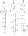
- FIG. 3 to 5 illustrate another aspect of an implant according to another embodiment of the invention and represent three implants 60, 70 and 80 seen in profile, that is to say according to their thickness.
- no curvature has been shown such as that(s) illustrated in the Figures 2b and 2c for the sake of simplification.
- the following description applies to implants whose body is elastically deformable or not, with single or double curvature along the direction of the thickness and whatever the shape and dimensions of the implant.
- the dimensions have been deliberately exaggerated for the sake of understanding.
- the body of the implant is adapted to allow a liquid flow of aqueous humor through said body ( Figure 3 ) or along it ( Figure 4 ), even through and also along the body ( Figure 5 ).
- the implant which is interposed between the ciliary body and the sclera must promote the flow/drainage of the aqueous humor collected at the level of the trabeculum towards the posterior part of the eye. This flow can be favored along the body (from its anterior border to its opposite posterior border) and/or through the body.
- the body of the implant 60 is pierced with orifices 62 passing through its thickness. These orifices 62 ensure the passage of a flow of aqueous humor through the body, from one of the two large opposite faces 60a to the other large opposite face 60b.
- the orifices are here shown aligned in a direction extending from the concave anterior edge 64 to the opposite posterior edge 66 in a section plane.
- the body is also pierced with a plurality of other orifices not shown which are located in other planes in front of and behind the section plane of the figure 3 .
- each hole through the body is not necessarily aligned as shown in the Figure 3 .
- each hole has a diameter of 50 ⁇ m and the body thickness is 200 ⁇ m.
- the body of the implant 70 comprises on at least one of its two large opposite faces 70a, 70b a relief which is capable of promoting a flow of aqueous humor along said at least one large face.
- the two large faces 70a and 70b are provided with such a relief which, as can be seen, is not necessarily identical from one face to the other. However, the relief may be the same from one face to the other.
- the relief takes for example the form of grooves or channels 72, 74 arranged respectively on the faces 70a, 70b, on the surface thereof. These grooves or channels 72, 74 are preferably arranged substantially parallel to a direction which extends from the concave anterior edge of the body to the opposite posterior edge thereof.
- the grooves or channels 72 are not arranged opposite the grooves or channels 74 so as not to weaken the constitution of the body. reducing its thickness locally at each location where the two grooves or channels would be opposite each other.
- the body of the implant can combine the through holes and the grooves: the holes are for example placed at the bottom of the grooves or between two adjacent grooves arranged on the same face.
- the 80 implant of the Figure 5 comprises, arranged on the large face 80a, grooves or channels 82 and, in an offset manner, arranged on the large opposite face 80b, grooves or channels 84.
- Through orifices 89 are made in the thickness of the body, at different locations, between the grooves of the two faces and/or on either side of the grooves. The number, dimensions and location of the grooves and orifices may vary.
- the grooves on the two opposite faces are arranged in a staggered pattern, for the same reasons.
- the relief can take the form of a roughness or texture conferred on one and/or the other of one of the two large opposite faces of the body by a known method.
- an implant according to a variant of the implant of the Figure 5 incorporates both through holes and a relief that is different from the aforementioned grooves or channels. This relief may be the same or vary from one face to the other.
- the relief described above in relation to the Figures 4 and 5 can be likened to local thickness variations of between 10 and 20 ⁇ m on each (or only one) of the two large opposite faces of the body. These local thickness variations occur along one or two dimensions perpendicular to the thickness which are small compared to the dimension(s) of the body perpendicular to the thickness (approximately 10 times smaller than the dimension(s)). It should be noted that the thickness variation is of the order of 10% of the general uniform thickness of the body.
- the body illustrated in the Figures 4 and 5 has a substantially uniform thickness, that is, a thickness which has a given general or nominal value and which locally accepts thickness variations between 10 and 20 ⁇ m.
- the material(s) constituting the body of the implant are chosen from the following materials: PTFE, polysiloxane, hydrophilic or hydrophobic acrylate hydrogels.
- the implant body has properties that release one or more substances.
- substances are, for example, anti-infectious and/or anti-inflammatory substances. They may therefore be antibiotic substances and/or cortisone or anti-cortisone substances.
- FIG. 6 illustrates the placement of an implant 90 using a first implantation method according to one embodiment of the invention.
- This first method is used in addition to a conventional anti-glaucomatous surgical procedure or in addition to any intraocular procedure when a lowering of intraocular pressure is desirable.
- Trabeculectomy and sclerectomy require cutting one or more scleral flap(s) from the eye which will be lifted in order to continue the procedure.
- a scleral flap 92 (illustrated in dotted lines on the Figure 6 ) is obtained by incising the sclera in one or two planes and at a variable depth, on three sides: two incisions 92a, 92b substantially parallel to each other which extend from the cornea 12 and away from it and a third incision 92c perpendicular to the other two incisions and at a distance from the cornea. The cut along three incisions thus made forms what is called one or more scleral flap(s).
- two incisions are made up to the ciliary body, inside flap 92, in order to be able to slide the implant between the deep scleral plane and the ciliary body.
- the incisions are spaced at least 2 mm apart.
- a single incision in the deep scleral plane is made to achieve the same goal.
- the implantation method used then includes a step of introducing a viscoelastic substance, for example hyaluronic acid type, through at least one of the incisions made, between the sclera and the ciliary body in order to separate these two previously joined tissues. This will allow the implant to be placed without trauma to the overlying and underlying structures.
- a viscoelastic substance for example hyaluronic acid type
- This step is implemented using an injection instrument such as an injection cannula with a diameter of around 20 to 30g.
- the implantation method also includes a step of introducing an instrument such as a blunt-edged forceps through one of the two incisions 94a, 94b which extend deep to the ciliary body.
- the forceps exit through the second incision and grasp the implant to place it between the sclera and the ciliary body.
- the position of the 90 implant is ensured as close as possible to the trabeculum (concentric to the limbus), as explained above, in order to collect the maximum amount of aqueous humor.
- Another type of instrument or device may be used to allow the placement, deployment of the implant and its positioning in the space between the sclera and the ciliary body (suprachoroidal space), such as an injector.
- the scleral flap(s) are folded back and sutured or not.
- FIG. 7 illustrates the placement of an implant 100 using a second implantation method according to an embodiment of the invention.
- This method is very similar to the first method except that the second method does not complement a conventional intervention but constitutes an intervention in itself.
- the final step of suturing the incisions is always optional.
- a single incision is made during this second method and is sufficient to install an implant in the interposition position between the sclera and the ciliary body.
- the 90 and 100 implants shown on the Figures 6 and 7 may be any of the implants described above.
- the methods for placing implants described above apply to any implant according to the invention and in particular to an ophthalmological implant for permanent interposition between the sclera and the uveal tissue which comprises a thin uveocompatible body formed from a single part, the body having a single substantially uniform thickness e which is at least less than 10 times the smallest of the two other dimensions of the body, the body of the implant comprising two opposite edges which are spaced apart from each other along one of the two dimensions perpendicular to the thickness, one of the edges called the anterior edge having, in projection in a plane perpendicular to the thickness, a concave curvature facing towards the outside of the body.
- the implant may further comprise any one (or several, or even all) of the characteristics presented in the general description as well as in the different embodiments and variants.
- the second method described applies to the placement of several implants according to the invention. Generally, at least one different incision (or even two in the example of the Figure 7 ) is to be practiced for the placement of each different implant.
- FIG 8 represents, in section, an implant according to an embodiment of the invention which has been put in place according to one of the methods described above.
- This section of a portion of an eye 110 represents the anterior chamber 112 which is arranged between the cornea 114 and the lens 116 delimited to its peripheral part by the iris 118.
- the sclera 122 is connected to the periphery of the cornea 114 via the limbus 124 (area of change of the radius of curvature between the sclera and the cornea).
- the sclera 122 covers the ciliary body 128 which is connected to the iris 118 and which includes the ciliary muscle 130 on which the sclera 122 rests.
- the trabeculum 134 located between the cornea and the iris acts as a filter and is crossed by the aqueous humor which circulates in the anterior chamber 112.
- Schlemm's canal 136 is located between the sclera and the cornea behind the trabecular meshwork 134.
- FIG. 9 is a more detailed and enlarged view of the structure of the iridocorneal angle without the implant. As shown in this figure, the scleral spur 132 on which the ciliary muscle 130 is inserted is located above the posterior portion 134a of the trabeculum 134.
- the separation produced at this location between the sclera and the ciliary body allows the aqueous humor to be permanently collected as close as possible to the zone of physiological uveo-scleral flow (the separation effect creates an area of less resistance to the flow of aqueous humor).
- Such an implant positioned in this way provides a significant gain in increasing physiological uveoscleral flow.
- Physiological uveoscleral outflow is increased by an additional fraction of outflow through the posterior part of the trabecular meshwork (ciliary trabecular meshwork), as shown in figure 8 by the arrows F5 located above and below the implant.
- the flow of this additional fraction is obtained thanks to the spacing effect of the implant between the sclera and the ciliary body, as close as possible to the trabeculum, without however damaging the latter.
- FIGS 10a and 10b illustrate the results of an experiment carried out on an eye bank eye that cannot be used for corneal transplants.
- a 15g weight corresponding to an intraocular pressure (IOP) simulating glaucoma conditions was placed on the top of the cornea of the eye.
- IOP intraocular pressure
- a pressure sensor was placed inside the eye to measure IOP. Successive IOP measurements (tonography) were recorded on the eye without the implant, then with the implant, in order to measure any possible effect of the implant on aqueous humor outflow, and therefore on IOP.
- An implant in accordance with the invention in particular with one embodiment of the invention, was placed in the eye through two scleral incisions following the surgical implantation method described with reference to the Figure 7 The implant was introduced into the supraciliary space.
- the implant in question is a 5x3mm implant, 150 ⁇ m thick, made of 25% hydrophilic acrylic material, known for its uveo-compatibility.
- the shape of the implant is that of implant 30 of the Figure 1 .
- Different measurement result curves illustrated on the Figure 10a are those obtained on the eye without an implant by exerting different local pressures on the eye.
- the different pressures exerted simulate the variations in IOP such as can be encountered in glaucoma and the consequences on the flow.
- the two curves with the squares and triangles are those for which local pressures were exerted.
Landscapes
- Health & Medical Sciences (AREA)
- Ophthalmology & Optometry (AREA)
- Animal Behavior & Ethology (AREA)
- Engineering & Computer Science (AREA)
- Biomedical Technology (AREA)
- Heart & Thoracic Surgery (AREA)
- Vascular Medicine (AREA)
- Life Sciences & Earth Sciences (AREA)
- General Health & Medical Sciences (AREA)
- Public Health (AREA)
- Veterinary Medicine (AREA)
- Surgery (AREA)
- Nuclear Medicine, Radiotherapy & Molecular Imaging (AREA)
- Prostheses (AREA)
Claims (15)
- Permanentes interpositionelles ophthalmologisches Implantat zwischen der Sklera und dem uvealen Gewebe, wobei das Implantat einen mit der Uvea kompatiblen Körper (20; 30; 40; 50) umfasst, der aus einem einzigen Teil gebildet ist, wobei der dünne Körper drei Dimensionen im Raum aufweist, d. h. eine Länge und eine Breite, die senkrecht zu einer Dicke sind, wobei der dünne Körper eine einzige im Wesentlichen gleichförmige Dicke (e) aufweist, die mindestens weniger als 10 Mal die kleinste der zwei anderen Dimensionen des Körpers ist, wobei der Körper des Implantats zwei einander gegenüberliegende Ränder (22, 24; 32, 34; 42; 44; 52, 54) aufweist, die voneinander gemäß einer der zwei senkrechten Dimensionen zur Dicke entfernt sind, wobei einer der Ränder, bezeichnet als vorderer Rand (22; 32; 42; 52), in Projektion in einer senkrechten Ebene zur Dicke eine konkave Krümmung aufweist, die hin zur Außenseite des Körpers gedreht ist, wobei die zwei einander gegenüberliegenden Ränder (22, 24; 32, 34; 42; 44; 52, 54) des Körpers, d. h. der vordere Rand und der gegenüberliegende hintere Rand, voneinander gemäß der kleinsten der zwei Dimensionen senkrecht zur Dicke entfernt sind, wobei die konkave Krümmung des vorderen Rands ermöglicht, das Implantat so nahe wie möglich am Trabekel zu positionieren, um auf permanente Weise das Augenkammerwasser zu sammeln, das dem Bereich des Uvea-Sklera-Ablaufs am nächsten ist.
- Interpositionelles ophthalmologisches Implantat nach Anspruch 1, dadurch gekennzeichnet, dass der vordere konkave Rand (22; 32; 42; 52) auf einer Dimension verdünnt ist, die im Bereich zwischen 100 und 400 µm liegt, wobei diese Dimension gemäß einer Richtung genommen wird, die sich zwischen den zwei einander gegenüberliegenden Rändern des Körpers erstreckt.
- Interpositionelles ophthalmologisches Implantat nach einem der vorhergehenden Ansprüche, dadurch gekennzeichnet, dass die konkave Krümmung des vorderen Rands (22; 32; 42; 52) einen Krümmungsradius darstellt, der im Bereich zwischen 5 und 7 mm liegt.
- Interpositionelles ophthalmologisches Implantat nach einem der vorhergehenden Ansprüche, dadurch gekennzeichnet, dass der Körper des Implantats (50) elastisch verformbar ist, so dass er gefaltet werden kann, ohne zu einer dauerhaften Verformung zu führen, um mit einem Mikroinstrument gehandhabt oder mit einem ophthalmologischen Injektionssystem injiziert zu werden.
- Interpositionelles ophthalmologisches Implantat nach Anspruch 4, dadurch gekennzeichnet, dass der Körper des Implantats (50) in einem verformten Zustand, in dem es wahrscheinlich ist, dass er als interpositionelles ophthalmologisches Implantat zwischen der Sklera und dem Uvea verwendet wird, eine zweite konkave Krümmung in einer Richtung senkrecht zu einer Ebene aufweist, die von den zwei Dimensionen des Implantats definiert wird, die senkrecht zu der Dicke (e) sind.
- Interpositionelles ophthalmologisches Implantat nach einem der vorhergehenden Ansprüche, dadurch gekennzeichnet, dass der Körper des Implantats aus einem Material hergestellt ist, das ein Young'sches Modul im Bereich zwischen 30 und 60 kg/cm2 aufweist.
- Interpositionelles ophthalmologisches Implantat nach einem der Ansprüche 1 bis 3, dadurch gekennzeichnet, dass der Körper des Implantats nicht elastisch verformbar ist und auf permanente Weise eine weitere konkave Krümmung in einer Richtung senkrecht zu einer Ebene umfasst, die von den zwei Dimensionen des Implantats definiert ist, die senkrecht zu der Dicke sind.
- Interpositionelles ophthalmologisches Implantat nach einem der vorhergehenden Ansprüche, dadurch gekennzeichnet, dass der Körper des Implantats zwei große einander gegenüberliegende Flächen (60a, 60b; 72a, 72b; 82a, 82b) aufweist, die voneinander gemäß der Dicke des Körpers beabstandet sind.
- Interpositionelles ophthalmologisches Implantat nach Anspruch 8, dadurch gekennzeichnet, dass der Körper des Implantats von Öffnungen (62; 89) durchbrochen ist, die seine Dicke durchqueren, oder der Körper des Implantats auf mindestens einer seiner zwei großen einander gegenüberliegenden Flächen (72a, 72b; 82a, 82b) ein Relief (72, 74; 82, 84) aufweist, das dazu in der Lage ist, ein Ablaufen der Augenkammerwassersentlang der mindestens einen großen Fläche zu begünstigen.
- Interpositionelles ophthalmologisches Implantat nach Anspruch 9, dadurch gekennzeichnet, dass das Relief der mindestens einen großen Fläche des Körpers die Form von Nuten (72, 74; 82, 84), die auf der mindestens einen großen Fläche angeordnet sind, oder einer Rauigkeit, die dieser zugewiesen ist, annimmt.
- Interpositionelles ophthalmologisches Implantat nach einem der vorhergehenden Ansprüche, dadurch gekennzeichnet, dass der Körper des Implantats mindestens ein Material umfasst, das aus den folgenden Materialien ausgewählt ist: PTFE, Polysiloxan, hydrophilen oder hydrophoben Acrylathydrogelen.
- Interpositionelles ophthalmologisches Implantat nach einem der vorhergehenden Ansprüche, dadurch gekennzeichnet, dass die Dicke (e) des Körpers des Implantats im Bereich zwischen 50 und 400 µm liegt.
- Interpositionelles ophthalmologisches Implantat nach einem der vorhergehenden Ansprüche, dadurch gekennzeichnet, dass der Körper des Implantats Eigenschaften der Freisetzung einer oder mehrerer Substanzen aufweist.
- Interpositionelles ophthalmologisches Implantat nach einem der vorhergehenden Ansprüche, dadurch gekennzeichnet, dass der Körper in Projektion auf einer Ebene senkrecht zur Dicke einen äußeren peripheren Umfang mit konvexer Geometrie aufweist, mit Ausnahme des Abschnitts des Körpers, der den vorderen konkaven Rand umfasst.
- Interpositionelles ophthalmologisches Implantat nach einem der vorhergehenden Ansprüche, dadurch gekennzeichnet, dass der andere der zwei gegenüberliegenden Ränder als hinterer Rand bezeichnet wird, wobei der hintere Rand vom vorderen Rand um eine Distanz von mindestens 3 mm beabstandet ist.
Applications Claiming Priority (2)
| Application Number | Priority Date | Filing Date | Title |
|---|---|---|---|
| FR1552732A FR3034308B1 (fr) | 2015-03-31 | 2015-03-31 | Implant ophtalmologique d'interposition |
| PCT/FR2016/050696 WO2016156727A1 (fr) | 2015-03-31 | 2016-03-25 | Implant ophtalmologique d'interposition |
Publications (3)
| Publication Number | Publication Date |
|---|---|
| EP3277237A1 EP3277237A1 (de) | 2018-02-07 |
| EP3277237C0 EP3277237C0 (de) | 2025-05-07 |
| EP3277237B1 true EP3277237B1 (de) | 2025-05-07 |
Family
ID=54014924
Family Applications (1)
| Application Number | Title | Priority Date | Filing Date |
|---|---|---|---|
| EP16719446.3A Active EP3277237B1 (de) | 2015-03-31 | 2016-03-25 | Interpositionelles ophthalmologisches implantat |
Country Status (14)
| Country | Link |
|---|---|
| US (1) | US10905589B2 (de) |
| EP (1) | EP3277237B1 (de) |
| JP (1) | JP6754773B2 (de) |
| KR (1) | KR102503560B1 (de) |
| CN (1) | CN107530191B (de) |
| BR (1) | BR112017020867B1 (de) |
| CA (1) | CA2980218C (de) |
| ES (1) | ES3036253T3 (de) |
| FR (1) | FR3034308B1 (de) |
| HU (1) | HUE072789T2 (de) |
| MX (1) | MX2017012524A (de) |
| PL (1) | PL3277237T3 (de) |
| RU (1) | RU2721299C2 (de) |
| WO (1) | WO2016156727A1 (de) |
Families Citing this family (5)
| Publication number | Priority date | Publication date | Assignee | Title |
|---|---|---|---|---|
| CN111772920B (zh) * | 2020-07-22 | 2025-01-07 | 苏州朗目医疗科技有限公司 | 青光眼引流装置及其引流植入物 |
| KR102812763B1 (ko) | 2020-08-13 | 2025-05-23 | 삼성전자주식회사 | 이미지 센서 |
| RU2761731C1 (ru) * | 2021-02-16 | 2021-12-13 | Юрий Юрьевич Калинников | Имплантат для введения в роговичный карман человеческого глаза для коррекции послеоперационной аномалии рефракции |
| FR3119763B1 (fr) | 2022-04-15 | 2024-04-12 | Ciliatech | Implant ophtalmologique d’interposition a excroissance de contact |
| FR3152375B1 (fr) | 2023-09-06 | 2025-07-18 | Ciliatech | Implant ophtalmologique d’interposition ayant une ou plusieurs excroissances sur sa surface superieure |
Citations (2)
| Publication number | Priority date | Publication date | Assignee | Title |
|---|---|---|---|---|
| US4521210A (en) * | 1982-12-27 | 1985-06-04 | Wong Vernon G | Eye implant for relieving glaucoma, and device and method for use therewith |
| US20040254521A1 (en) * | 2003-06-16 | 2004-12-16 | Solx, Inc. | Shunt for the treatment of glaucoma |
Family Cites Families (12)
| Publication number | Priority date | Publication date | Assignee | Title |
|---|---|---|---|---|
| FR2721499B1 (fr) * | 1994-06-22 | 1997-01-03 | Opsia | Implant de trabéculectomie. |
| US5704907A (en) * | 1994-07-22 | 1998-01-06 | Wound Healing Of Oklahoma | Method and apparatus for lowering the intraocular pressure of an eye |
| US6464724B1 (en) * | 1999-04-26 | 2002-10-15 | Gmp Vision Solutions, Inc. | Stent device and method for treating glaucoma |
| FR2813521B1 (fr) * | 2000-09-01 | 2003-06-13 | Ioltechnologie Production | Drain a glaucome |
| US7749528B2 (en) * | 2001-08-29 | 2010-07-06 | Ricardo Azevedo Pontes De Carvalho | Implantable and sealable medical device for unidirectional delivery of therapeutic agents to tissues |
| ATE550056T1 (de) * | 2002-07-19 | 2012-04-15 | Univ Yale | Uvosklerale entwässerungsvorrichtung |
| US20040193262A1 (en) * | 2003-03-29 | 2004-09-30 | Shadduck John H. | Implants for treating ocular hypertension, methods of use and methods of fabrication |
| RU2394534C2 (ru) * | 2007-12-27 | 2010-07-20 | Государственное учреждение здравоохранения Самарская клиническая офтальмологическая больница им. Т.И. Ерошевского | Способ лечения открытоугольной глаукомы |
| EP3735947B1 (de) | 2009-01-28 | 2022-05-04 | Alcon Inc. | System zum einbringen eines augenimplantats |
| TW201127359A (en) * | 2009-09-21 | 2011-08-16 | Vidus Ocular Inc | Uveoscleral drainage device |
| US9370444B2 (en) * | 2010-10-12 | 2016-06-21 | Emmett T. Cunningham, JR. | Subconjunctival conformer device and uses thereof |
| EP2654715B1 (de) | 2010-11-24 | 2017-01-25 | Dose Medical Corporation | Arzneimittelfreisetzendes augenimplantat |
-
2015
- 2015-03-31 FR FR1552732A patent/FR3034308B1/fr active Active
-
2016
- 2016-03-25 HU HUE16719446A patent/HUE072789T2/hu unknown
- 2016-03-25 KR KR1020177031635A patent/KR102503560B1/ko active Active
- 2016-03-25 PL PL16719446.3T patent/PL3277237T3/pl unknown
- 2016-03-25 US US15/562,333 patent/US10905589B2/en active Active
- 2016-03-25 RU RU2017133016A patent/RU2721299C2/ru active
- 2016-03-25 CN CN201680019747.9A patent/CN107530191B/zh active Active
- 2016-03-25 ES ES16719446T patent/ES3036253T3/es active Active
- 2016-03-25 BR BR112017020867-9A patent/BR112017020867B1/pt active IP Right Grant
- 2016-03-25 CA CA2980218A patent/CA2980218C/fr active Active
- 2016-03-25 EP EP16719446.3A patent/EP3277237B1/de active Active
- 2016-03-25 MX MX2017012524A patent/MX2017012524A/es unknown
- 2016-03-25 WO PCT/FR2016/050696 patent/WO2016156727A1/fr not_active Ceased
- 2016-03-25 JP JP2017551029A patent/JP6754773B2/ja active Active
Patent Citations (2)
| Publication number | Priority date | Publication date | Assignee | Title |
|---|---|---|---|---|
| US4521210A (en) * | 1982-12-27 | 1985-06-04 | Wong Vernon G | Eye implant for relieving glaucoma, and device and method for use therewith |
| US20040254521A1 (en) * | 2003-06-16 | 2004-12-16 | Solx, Inc. | Shunt for the treatment of glaucoma |
Also Published As
| Publication number | Publication date |
|---|---|
| CN107530191B (zh) | 2021-08-20 |
| CA2980218A1 (fr) | 2016-10-06 |
| RU2017133016A3 (de) | 2019-08-05 |
| CA2980218C (fr) | 2023-05-23 |
| EP3277237A1 (de) | 2018-02-07 |
| JP6754773B2 (ja) | 2020-09-16 |
| JP2018512942A (ja) | 2018-05-24 |
| RU2721299C2 (ru) | 2020-05-18 |
| US10905589B2 (en) | 2021-02-02 |
| KR20170134578A (ko) | 2017-12-06 |
| BR112017020867B1 (pt) | 2022-12-06 |
| HUE072789T2 (hu) | 2025-12-28 |
| MX2017012524A (es) | 2018-02-23 |
| US20180353329A1 (en) | 2018-12-13 |
| EP3277237C0 (de) | 2025-05-07 |
| FR3034308B1 (fr) | 2022-01-21 |
| ES3036253T3 (en) | 2025-09-18 |
| CN107530191A (zh) | 2018-01-02 |
| RU2017133016A (ru) | 2019-05-06 |
| KR102503560B1 (ko) | 2023-02-27 |
| BR112017020867A2 (pt) | 2018-07-10 |
| FR3034308A1 (fr) | 2016-10-07 |
| WO2016156727A1 (fr) | 2016-10-06 |
| PL3277237T3 (pl) | 2025-11-17 |
Similar Documents
| Publication | Publication Date | Title |
|---|---|---|
| EP3277237B1 (de) | Interpositionelles ophthalmologisches implantat | |
| EP1313416B1 (de) | Drainageröhre zur behandlung des erhöhten innendrudrucks | |
| EP0993281B1 (de) | Intraokuläres implantat | |
| FR2530457A1 (fr) | Systeme perfectionne de fixation pour des structures de lentilles intra-oculaires | |
| WO1995008310A1 (fr) | Dispositif implantable pour le traitement des ×demes | |
| FR2841767A1 (fr) | Lentille intraoculaire accommodative | |
| US10070953B2 (en) | Corneal implant and method of delivering a corneal implant | |
| FR2764797A1 (fr) | Forme pour incision corneenne multiplans | |
| FR2963229A1 (fr) | Implant intraoculaire a elements d'accrochage. | |
| FR2997624A1 (fr) | Implant intraoculaire pseudophake de rhexis | |
| EP4507639A1 (de) | Ophthalmologisches zwischenpositionierungsimplantat mit eingriffsvorsprung | |
| EP0067765A1 (de) | Intraoculares Implantat | |
| BE1027321B1 (fr) | Implant phaque de chambre postérieure | |
| FR2611487A1 (fr) | Dispositif chirurgical ophtalmologique compose d'un element porteur et d'un element porte qui est une lentille intra-oculaire | |
| WO2025052071A1 (fr) | Implant ophtalmologique d'interposition ayant une ou plusieurs excroissances sur sa surface superieure | |
| FR3067591A1 (fr) | Implant intraoculaire pour le traitement de la cataracte chez l'homme et l'animal | |
| BE1029854A1 (fr) | Lentille intraoculaire phaque de chambre postérieure | |
| Miyake | Cataract surgical problem: Reply# 3 | |
| Miyake | Consultation: Reply# 3 | |
| FR2899093A1 (fr) | Lentille intraoculaire refractive de chambre anterieure, notamment pour oeil phaque. | |
| FR2819716A1 (fr) | Dispositif d'ablation de la sclere | |
| RU2003129112A (ru) | Способ кератопластики у больных с высоким риском отторжения трансплантата |
Legal Events
| Date | Code | Title | Description |
|---|---|---|---|
| STAA | Information on the status of an ep patent application or granted ep patent |
Free format text: STATUS: THE INTERNATIONAL PUBLICATION HAS BEEN MADE |
|
| PUAI | Public reference made under article 153(3) epc to a published international application that has entered the european phase |
Free format text: ORIGINAL CODE: 0009012 |
|
| STAA | Information on the status of an ep patent application or granted ep patent |
Free format text: STATUS: REQUEST FOR EXAMINATION WAS MADE |
|
| 17P | Request for examination filed |
Effective date: 20171027 |
|
| AK | Designated contracting states |
Kind code of ref document: A1 Designated state(s): AL AT BE BG CH CY CZ DE DK EE ES FI FR GB GR HR HU IE IS IT LI LT LU LV MC MK MT NL NO PL PT RO RS SE SI SK SM TR |
|
| AX | Request for extension of the european patent |
Extension state: BA ME |
|
| DAV | Request for validation of the european patent (deleted) | ||
| DAX | Request for extension of the european patent (deleted) | ||
| RAP1 | Party data changed (applicant data changed or rights of an application transferred) |
Owner name: CILIATECH |
|
| RIN1 | Information on inventor provided before grant (corrected) |
Inventor name: SOURDILLE PHILIPPE |
|
| STAA | Information on the status of an ep patent application or granted ep patent |
Free format text: STATUS: EXAMINATION IS IN PROGRESS |
|
| 17Q | First examination report despatched |
Effective date: 20201222 |
|
| GRAP | Despatch of communication of intention to grant a patent |
Free format text: ORIGINAL CODE: EPIDOSNIGR1 |
|
| STAA | Information on the status of an ep patent application or granted ep patent |
Free format text: STATUS: GRANT OF PATENT IS INTENDED |
|
| INTG | Intention to grant announced |
Effective date: 20250114 |
|
| GRAS | Grant fee paid |
Free format text: ORIGINAL CODE: EPIDOSNIGR3 |
|
| GRAA | (expected) grant |
Free format text: ORIGINAL CODE: 0009210 |
|
| STAA | Information on the status of an ep patent application or granted ep patent |
Free format text: STATUS: THE PATENT HAS BEEN GRANTED |
|
| AK | Designated contracting states |
Kind code of ref document: B1 Designated state(s): AL AT BE BG CH CY CZ DE DK EE ES FI FR GB GR HR HU IE IS IT LI LT LU LV MC MK MT NL NO PL PT RO RS SE SI SK SM TR |
|
| REG | Reference to a national code |
Ref country code: GB Ref legal event code: FG4D Free format text: NOT ENGLISH |
|
| REG | Reference to a national code |
Ref country code: CH Ref legal event code: EP |
|
| REG | Reference to a national code |
Ref country code: DE Ref legal event code: R096 Ref document number: 602016092155 Country of ref document: DE |
|
| REG | Reference to a national code |
Ref country code: IE Ref legal event code: FG4D Free format text: LANGUAGE OF EP DOCUMENT: FRENCH |
|
| U01 | Request for unitary effect filed |
Effective date: 20250528 |
|
| U07 | Unitary effect registered |
Designated state(s): AT BE BG DE DK EE FI FR IT LT LU LV MT NL PT RO SE SI Effective date: 20250606 |
|
| REG | Reference to a national code |
Ref country code: ES Ref legal event code: FG2A Ref document number: 3036253 Country of ref document: ES Kind code of ref document: T3 Effective date: 20250918 |
|
| PG25 | Lapsed in a contracting state [announced via postgrant information from national office to epo] |
Ref country code: NO Free format text: LAPSE BECAUSE OF FAILURE TO SUBMIT A TRANSLATION OF THE DESCRIPTION OR TO PAY THE FEE WITHIN THE PRESCRIBED TIME-LIMIT Effective date: 20250807 |
|
| PG25 | Lapsed in a contracting state [announced via postgrant information from national office to epo] |
Ref country code: HR Free format text: LAPSE BECAUSE OF FAILURE TO SUBMIT A TRANSLATION OF THE DESCRIPTION OR TO PAY THE FEE WITHIN THE PRESCRIBED TIME-LIMIT Effective date: 20250507 |
|
| PG25 | Lapsed in a contracting state [announced via postgrant information from national office to epo] |
Ref country code: RS Free format text: LAPSE BECAUSE OF FAILURE TO SUBMIT A TRANSLATION OF THE DESCRIPTION OR TO PAY THE FEE WITHIN THE PRESCRIBED TIME-LIMIT Effective date: 20250807 |
|
| PG25 | Lapsed in a contracting state [announced via postgrant information from national office to epo] |
Ref country code: IS Free format text: LAPSE BECAUSE OF FAILURE TO SUBMIT A TRANSLATION OF THE DESCRIPTION OR TO PAY THE FEE WITHIN THE PRESCRIBED TIME-LIMIT Effective date: 20250907 |
|
| REG | Reference to a national code |
Ref country code: GR Ref legal event code: EP Ref document number: 20250401590 Country of ref document: GR Effective date: 20251009 |
|
| REG | Reference to a national code |
Ref country code: HU Ref legal event code: AG4A Ref document number: E072789 Country of ref document: HU |
|
| PG25 | Lapsed in a contracting state [announced via postgrant information from national office to epo] |
Ref country code: SM Free format text: LAPSE BECAUSE OF FAILURE TO SUBMIT A TRANSLATION OF THE DESCRIPTION OR TO PAY THE FEE WITHIN THE PRESCRIBED TIME-LIMIT Effective date: 20250507 |
|
| PG25 | Lapsed in a contracting state [announced via postgrant information from national office to epo] |
Ref country code: CZ Free format text: LAPSE BECAUSE OF FAILURE TO SUBMIT A TRANSLATION OF THE DESCRIPTION OR TO PAY THE FEE WITHIN THE PRESCRIBED TIME-LIMIT Effective date: 20250507 |
|
| PG25 | Lapsed in a contracting state [announced via postgrant information from national office to epo] |
Ref country code: SK Free format text: LAPSE BECAUSE OF FAILURE TO SUBMIT A TRANSLATION OF THE DESCRIPTION OR TO PAY THE FEE WITHIN THE PRESCRIBED TIME-LIMIT Effective date: 20250507 |
|
| PLBE | No opposition filed within time limit |
Free format text: ORIGINAL CODE: 0009261 |
|
| STAA | Information on the status of an ep patent application or granted ep patent |
Free format text: STATUS: NO OPPOSITION FILED WITHIN TIME LIMIT |
|
| REG | Reference to a national code |
Ref country code: CH Ref legal event code: L10 Free format text: ST27 STATUS EVENT CODE: U-0-0-L10-L00 (AS PROVIDED BY THE NATIONAL OFFICE) Effective date: 20260318 |
|
| REG | Reference to a national code |
Ref country code: CH Ref legal event code: U11 Free format text: ST27 STATUS EVENT CODE: U-0-0-U10-U11 (AS PROVIDED BY THE NATIONAL OFFICE) Effective date: 20260401 |
|
| PGFP | Annual fee paid to national office [announced via postgrant information from national office to epo] |
Ref country code: GB Payment date: 20260324 Year of fee payment: 11 |
|
| 26N | No opposition filed |
Effective date: 20260210 |
|
| PGFP | Annual fee paid to national office [announced via postgrant information from national office to epo] |
Ref country code: TR Payment date: 20260323 Year of fee payment: 11 |
|
| U20 | Renewal fee for the european patent with unitary effect paid |
Year of fee payment: 11 Effective date: 20260326 |