EP3277378B1 - Appareil pour le traitement d'une valvulopathie - Google Patents
Appareil pour le traitement d'une valvulopathie Download PDFInfo
- Publication number
- EP3277378B1 EP3277378B1 EP16722358.5A EP16722358A EP3277378B1 EP 3277378 B1 EP3277378 B1 EP 3277378B1 EP 16722358 A EP16722358 A EP 16722358A EP 3277378 B1 EP3277378 B1 EP 3277378B1
- Authority
- EP
- European Patent Office
- Prior art keywords
- focused ultrasound
- ultrasound waves
- focused
- ultrasound probe
- valve
- Prior art date
- Legal status (The legal status is an assumption and is not a legal conclusion. Google has not performed a legal analysis and makes no representation as to the accuracy of the status listed.)
- Active
Links
Images






Classifications
-
- A—HUMAN NECESSITIES
- A61—MEDICAL OR VETERINARY SCIENCE; HYGIENE
- A61B—DIAGNOSIS; SURGERY; IDENTIFICATION
- A61B8/00—Diagnosis using ultrasonic, sonic or infrasonic waves
- A61B8/06—Measuring blood flow
-
- A—HUMAN NECESSITIES
- A61—MEDICAL OR VETERINARY SCIENCE; HYGIENE
- A61B—DIAGNOSIS; SURGERY; IDENTIFICATION
- A61B8/00—Diagnosis using ultrasonic, sonic or infrasonic waves
- A61B8/04—Measuring blood pressure
-
- A—HUMAN NECESSITIES
- A61—MEDICAL OR VETERINARY SCIENCE; HYGIENE
- A61B—DIAGNOSIS; SURGERY; IDENTIFICATION
- A61B8/00—Diagnosis using ultrasonic, sonic or infrasonic waves
- A61B8/08—Clinical applications
- A61B8/0883—Clinical applications for diagnosis of the heart
-
- A—HUMAN NECESSITIES
- A61—MEDICAL OR VETERINARY SCIENCE; HYGIENE
- A61B—DIAGNOSIS; SURGERY; IDENTIFICATION
- A61B8/00—Diagnosis using ultrasonic, sonic or infrasonic waves
- A61B8/12—Diagnosis using ultrasonic, sonic or infrasonic waves in body cavities or body tracts, e.g. by using catheters
-
- A—HUMAN NECESSITIES
- A61—MEDICAL OR VETERINARY SCIENCE; HYGIENE
- A61N—ELECTROTHERAPY; MAGNETOTHERAPY; RADIATION THERAPY; ULTRASOUND THERAPY
- A61N7/00—Ultrasound therapy
- A61N7/02—Localised ultrasound hyperthermia
-
- A—HUMAN NECESSITIES
- A61—MEDICAL OR VETERINARY SCIENCE; HYGIENE
- A61B—DIAGNOSIS; SURGERY; IDENTIFICATION
- A61B17/00—Surgical instruments, devices or methods
- A61B17/22—Implements for squeezing-off ulcers or the like on inner organs of the body; Implements for scraping-out cavities of body organs, e.g. bones; for invasive removal or destruction of calculus using mechanical vibrations; for removing obstructions in blood vessels, not otherwise provided for
- A61B17/22004—Implements for squeezing-off ulcers or the like on inner organs of the body; Implements for scraping-out cavities of body organs, e.g. bones; for invasive removal or destruction of calculus using mechanical vibrations; for removing obstructions in blood vessels, not otherwise provided for using mechanical vibrations, e.g. ultrasonic shock waves
-
- A—HUMAN NECESSITIES
- A61—MEDICAL OR VETERINARY SCIENCE; HYGIENE
- A61B—DIAGNOSIS; SURGERY; IDENTIFICATION
- A61B17/00—Surgical instruments, devices or methods
- A61B17/22—Implements for squeezing-off ulcers or the like on inner organs of the body; Implements for scraping-out cavities of body organs, e.g. bones; for invasive removal or destruction of calculus using mechanical vibrations; for removing obstructions in blood vessels, not otherwise provided for
- A61B17/225—Implements for squeezing-off ulcers or the like on inner organs of the body; Implements for scraping-out cavities of body organs, e.g. bones; for invasive removal or destruction of calculus using mechanical vibrations; for removing obstructions in blood vessels, not otherwise provided for for extracorporeal shock wave lithotripsy [ESWL], e.g. by using ultrasonic waves
-
- A—HUMAN NECESSITIES
- A61—MEDICAL OR VETERINARY SCIENCE; HYGIENE
- A61B—DIAGNOSIS; SURGERY; IDENTIFICATION
- A61B17/00—Surgical instruments, devices or methods
- A61B2017/00367—Details of actuation of instruments, e.g. relations between pushing buttons, or the like, and activation of the tool, working tip, or the like
- A61B2017/00398—Details of actuation of instruments, e.g. relations between pushing buttons, or the like, and activation of the tool, working tip, or the like using powered actuators, e.g. stepper motors, solenoids
-
- A—HUMAN NECESSITIES
- A61—MEDICAL OR VETERINARY SCIENCE; HYGIENE
- A61B—DIAGNOSIS; SURGERY; IDENTIFICATION
- A61B17/00—Surgical instruments, devices or methods
- A61B17/22—Implements for squeezing-off ulcers or the like on inner organs of the body; Implements for scraping-out cavities of body organs, e.g. bones; for invasive removal or destruction of calculus using mechanical vibrations; for removing obstructions in blood vessels, not otherwise provided for
- A61B2017/22098—Decalcification of valves
-
- A—HUMAN NECESSITIES
- A61—MEDICAL OR VETERINARY SCIENCE; HYGIENE
- A61B—DIAGNOSIS; SURGERY; IDENTIFICATION
- A61B34/00—Computer-aided surgery; Manipulators or robots specially adapted for use in surgery
- A61B34/20—Surgical navigation systems; Devices for tracking or guiding surgical instruments, e.g. for frameless stereotaxis
- A61B2034/2046—Tracking techniques
- A61B2034/2063—Acoustic tracking systems, e.g. using ultrasound
-
- A—HUMAN NECESSITIES
- A61—MEDICAL OR VETERINARY SCIENCE; HYGIENE
- A61B—DIAGNOSIS; SURGERY; IDENTIFICATION
- A61B34/00—Computer-aided surgery; Manipulators or robots specially adapted for use in surgery
- A61B34/20—Surgical navigation systems; Devices for tracking or guiding surgical instruments, e.g. for frameless stereotaxis
- A61B2034/2046—Tracking techniques
- A61B2034/2065—Tracking using image or pattern recognition
-
- A—HUMAN NECESSITIES
- A61—MEDICAL OR VETERINARY SCIENCE; HYGIENE
- A61B—DIAGNOSIS; SURGERY; IDENTIFICATION
- A61B90/00—Instruments, implements or accessories specially adapted for surgery or diagnosis and not covered by any of the groups A61B1/00 - A61B50/00, e.g. for luxation treatment or for protecting wound edges
- A61B90/36—Image-producing devices or illumination devices not otherwise provided for
- A61B90/37—Surgical systems with images on a monitor during operation
- A61B2090/374—NMR or MRI
-
- A—HUMAN NECESSITIES
- A61—MEDICAL OR VETERINARY SCIENCE; HYGIENE
- A61B—DIAGNOSIS; SURGERY; IDENTIFICATION
- A61B90/00—Instruments, implements or accessories specially adapted for surgery or diagnosis and not covered by any of the groups A61B1/00 - A61B50/00, e.g. for luxation treatment or for protecting wound edges
- A61B90/36—Image-producing devices or illumination devices not otherwise provided for
- A61B90/37—Surgical systems with images on a monitor during operation
- A61B2090/376—Surgical systems with images on a monitor during operation using X-rays, e.g. fluoroscopy
-
- A—HUMAN NECESSITIES
- A61—MEDICAL OR VETERINARY SCIENCE; HYGIENE
- A61B—DIAGNOSIS; SURGERY; IDENTIFICATION
- A61B90/00—Instruments, implements or accessories specially adapted for surgery or diagnosis and not covered by any of the groups A61B1/00 - A61B50/00, e.g. for luxation treatment or for protecting wound edges
- A61B90/36—Image-producing devices or illumination devices not otherwise provided for
- A61B90/37—Surgical systems with images on a monitor during operation
- A61B2090/378—Surgical systems with images on a monitor during operation using ultrasound
-
- A—HUMAN NECESSITIES
- A61—MEDICAL OR VETERINARY SCIENCE; HYGIENE
- A61B—DIAGNOSIS; SURGERY; IDENTIFICATION
- A61B90/00—Instruments, implements or accessories specially adapted for surgery or diagnosis and not covered by any of the groups A61B1/00 - A61B50/00, e.g. for luxation treatment or for protecting wound edges
- A61B90/36—Image-producing devices or illumination devices not otherwise provided for
- A61B90/37—Surgical systems with images on a monitor during operation
- A61B2090/378—Surgical systems with images on a monitor during operation using ultrasound
- A61B2090/3782—Surgical systems with images on a monitor during operation using ultrasound transmitter or receiver in catheter or minimal invasive instrument
-
- A—HUMAN NECESSITIES
- A61—MEDICAL OR VETERINARY SCIENCE; HYGIENE
- A61B—DIAGNOSIS; SURGERY; IDENTIFICATION
- A61B90/00—Instruments, implements or accessories specially adapted for surgery or diagnosis and not covered by any of the groups A61B1/00 - A61B50/00, e.g. for luxation treatment or for protecting wound edges
- A61B90/36—Image-producing devices or illumination devices not otherwise provided for
- A61B90/37—Surgical systems with images on a monitor during operation
- A61B2090/378—Surgical systems with images on a monitor during operation using ultrasound
- A61B2090/3782—Surgical systems with images on a monitor during operation using ultrasound transmitter or receiver in catheter or minimal invasive instrument
- A61B2090/3784—Surgical systems with images on a monitor during operation using ultrasound transmitter or receiver in catheter or minimal invasive instrument both receiver and transmitter being in the instrument or receiver being also transmitter
-
- A—HUMAN NECESSITIES
- A61—MEDICAL OR VETERINARY SCIENCE; HYGIENE
- A61B—DIAGNOSIS; SURGERY; IDENTIFICATION
- A61B2576/00—Medical imaging apparatus involving image processing or analysis
- A61B2576/02—Medical imaging apparatus involving image processing or analysis specially adapted for a particular organ or body part
- A61B2576/023—Medical imaging apparatus involving image processing or analysis specially adapted for a particular organ or body part for the heart
-
- A—HUMAN NECESSITIES
- A61—MEDICAL OR VETERINARY SCIENCE; HYGIENE
- A61B—DIAGNOSIS; SURGERY; IDENTIFICATION
- A61B34/00—Computer-aided surgery; Manipulators or robots specially adapted for use in surgery
- A61B34/30—Surgical robots
-
- A—HUMAN NECESSITIES
- A61—MEDICAL OR VETERINARY SCIENCE; HYGIENE
- A61B—DIAGNOSIS; SURGERY; IDENTIFICATION
- A61B5/00—Measuring for diagnostic purposes; Identification of persons
- A61B5/0048—Detecting, measuring or recording by applying mechanical forces or stimuli
- A61B5/0053—Detecting, measuring or recording by applying mechanical forces or stimuli by applying pressure, e.g. compression, indentation, palpation, grasping, gauging
-
- A—HUMAN NECESSITIES
- A61—MEDICAL OR VETERINARY SCIENCE; HYGIENE
- A61B—DIAGNOSIS; SURGERY; IDENTIFICATION
- A61B5/00—Measuring for diagnostic purposes; Identification of persons
- A61B5/02—Detecting, measuring or recording for evaluating the cardiovascular system, e.g. pulse, heart rate, blood pressure or blood flow
- A61B5/021—Measuring pressure in heart or blood vessels
- A61B5/0215—Measuring pressure in heart or blood vessels by means inserted into the body
-
- A—HUMAN NECESSITIES
- A61—MEDICAL OR VETERINARY SCIENCE; HYGIENE
- A61B—DIAGNOSIS; SURGERY; IDENTIFICATION
- A61B8/00—Diagnosis using ultrasonic, sonic or infrasonic waves
- A61B8/44—Constructional features of the ultrasonic, sonic or infrasonic diagnostic device
- A61B8/4444—Constructional features of the ultrasonic, sonic or infrasonic diagnostic device related to the probe
- A61B8/445—Details of catheter construction
-
- A—HUMAN NECESSITIES
- A61—MEDICAL OR VETERINARY SCIENCE; HYGIENE
- A61B—DIAGNOSIS; SURGERY; IDENTIFICATION
- A61B8/00—Diagnosis using ultrasonic, sonic or infrasonic waves
- A61B8/44—Constructional features of the ultrasonic, sonic or infrasonic diagnostic device
- A61B8/4483—Constructional features of the ultrasonic, sonic or infrasonic diagnostic device characterised by features of the ultrasound transducer
-
- A—HUMAN NECESSITIES
- A61—MEDICAL OR VETERINARY SCIENCE; HYGIENE
- A61B—DIAGNOSIS; SURGERY; IDENTIFICATION
- A61B8/00—Diagnosis using ultrasonic, sonic or infrasonic waves
- A61B8/48—Diagnostic techniques
- A61B8/485—Diagnostic techniques involving measuring strain or elastic properties
-
- A—HUMAN NECESSITIES
- A61—MEDICAL OR VETERINARY SCIENCE; HYGIENE
- A61B—DIAGNOSIS; SURGERY; IDENTIFICATION
- A61B8/00—Diagnosis using ultrasonic, sonic or infrasonic waves
- A61B8/48—Diagnostic techniques
- A61B8/488—Diagnostic techniques involving Doppler signals
-
- A—HUMAN NECESSITIES
- A61—MEDICAL OR VETERINARY SCIENCE; HYGIENE
- A61N—ELECTROTHERAPY; MAGNETOTHERAPY; RADIATION THERAPY; ULTRASOUND THERAPY
- A61N7/00—Ultrasound therapy
- A61N2007/0004—Applications of ultrasound therapy
-
- A—HUMAN NECESSITIES
- A61—MEDICAL OR VETERINARY SCIENCE; HYGIENE
- A61N—ELECTROTHERAPY; MAGNETOTHERAPY; RADIATION THERAPY; ULTRASOUND THERAPY
- A61N7/00—Ultrasound therapy
- A61N2007/0039—Ultrasound therapy using microbubbles
-
- A—HUMAN NECESSITIES
- A61—MEDICAL OR VETERINARY SCIENCE; HYGIENE
- A61N—ELECTROTHERAPY; MAGNETOTHERAPY; RADIATION THERAPY; ULTRASOUND THERAPY
- A61N7/00—Ultrasound therapy
- A61N2007/0052—Ultrasound therapy using the same transducer for therapy and imaging
-
- A—HUMAN NECESSITIES
- A61—MEDICAL OR VETERINARY SCIENCE; HYGIENE
- A61N—ELECTROTHERAPY; MAGNETOTHERAPY; RADIATION THERAPY; ULTRASOUND THERAPY
- A61N7/00—Ultrasound therapy
- A61N2007/0086—Beam steering
-
- A—HUMAN NECESSITIES
- A61—MEDICAL OR VETERINARY SCIENCE; HYGIENE
- A61N—ELECTROTHERAPY; MAGNETOTHERAPY; RADIATION THERAPY; ULTRASOUND THERAPY
- A61N7/00—Ultrasound therapy
- A61N2007/0086—Beam steering
- A61N2007/0095—Beam steering by modifying an excitation signal
-
- A—HUMAN NECESSITIES
- A61—MEDICAL OR VETERINARY SCIENCE; HYGIENE
- A61N—ELECTROTHERAPY; MAGNETOTHERAPY; RADIATION THERAPY; ULTRASOUND THERAPY
- A61N7/00—Ultrasound therapy
-
- G—PHYSICS
- G16—INFORMATION AND COMMUNICATION TECHNOLOGY [ICT] SPECIALLY ADAPTED FOR SPECIFIC APPLICATION FIELDS
- G16H—HEALTHCARE INFORMATICS, i.e. INFORMATION AND COMMUNICATION TECHNOLOGY [ICT] SPECIALLY ADAPTED FOR THE HANDLING OR PROCESSING OF MEDICAL OR HEALTHCARE DATA
- G16H30/00—ICT specially adapted for the handling or processing of medical images
- G16H30/40—ICT specially adapted for the handling or processing of medical images for processing medical images, e.g. editing
Definitions
- the instant invention relates to apparatuses for treatment or prevention of valvular stenosis.
- Valvular stenosis also called heart valve disease or narrowed valve, occurs when tissues forming a cardiac valve leaflets become stiffer thereby narrowing the valve opening and reducing the amount of blood that can flow through it.
- Valvular stenosis may occur in any of the four valves of the heart: the aortic valve, the mitral valve, the tricuspid valve or the pulmonic valve.
- One of the known causes of valvular stenosis is a fibro-calcific degeneration of the valve leaflets wherein one or more of the valve leaflets become calcified and thus thickened and hardened, resulting in a narrowed valve opening.
- Open surgery is done through a median sternotomy and involves a cardiopulmonary bypass of the patient. It is thus a major operation that conveys significant risk of death or serious complications. Moreover, a large class of older patients, as well as those who are frail and/or have multiple comorbidities, face significantly higher surgical risks and are thus excluded from the scope of application of this method.
- Tissue valves come with no requirement for anticoagulation therapy, which reduces the incidence of bleeding.
- the lifetime of a tissue valve is typically 10 to 15 years, often less in younger patients. Over this time the valve will likely be degenerating to the point of requiring replacement, which again carries a significant risk of death.
- tissue valves are also subject to valvular diseases; in particular, they may also develop fibro-calcific degeneration requiring an early replacement.
- the instant invention has notably for object to improve this situation.
- an exemplary method for treating or preventing a valvular disease comprises:
- cardiac valve should be construed as designating both native valves and bioprostheses.
- an apparatus for treating or preventing a valvular disease comprising:
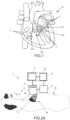
- FIG 1 illustrates a heart H of a patient which is a mammalian, for instance a human.
- the heart comprises four cardiac valves C1, C2, C3, C4 that determine the pathway of blood flow through the heart: the mitral valve C1, the tricuspid valve C2, the aortic valve C3 and the pulmonary valve C4.
- Each cardiac valve C allows blood to flow in only one direction through the heart H by opening or closing incumbent on differential blood pressure on each side of the valve.
- each cardiac valve C comprises leaflets L, also called cusps, which are thin tissue layers that are able to be closed together, to seal the valve and prevent backflow, and pushed (i.e. bended) open to allow blood flow.
- the mitral valve C1 usually has two leaflets L, whereas the three others cardiac valves C2, C3, C4 usually have three leaflets L (only two leaflets are show on Figure 1 for each cardiac valve).
- the leaflets are fixed to an annulus of the cardiac valve C.
- the annulus is a ring composed of fibrous tissue and forming a partial or complete valvular ring around the cardiac valve C.
- Valvular stenosis occurs when a cardiac valve C is narrowed. Any of the heart valves C can be affected, resulting in so-called mitral valve stenosis, tricuspid valve stenosis, pulmonary valve stenosis or aortic valve stenosis.
- Valvular stenosis can arise from various causes and may be congenital (inborn) or acquired. Valvular stenosis causes serious threat to the life of the patient. In the case of aortic stenosis for instance, it is estimated that, without repair, the chance of death at five years is about 50% and at 10 years is about 90%.
- valve stenosis In developed society, a major cause of valve stenosis is an age-related progressive calcification of the valve. It is estimated that approximately 2% of people over the age of 65, 3% of people over age 75, and 4% percent of people over age 85 are affected by this condition.
- the process is currently understood as involving one or several leaflets L of a cardiac valve C becoming hardened and thickened and, as a result, the opening surface of the cardiac valve being reduced.
- Cardiac valve leaflets L are thin tissue layers with a thickness normally of the order of 0.5-1.5 mm. With aging of the patient, the thickness of the leaflets L may increases to around 3-5 mm with an associated hardening of the leaflets.
- a cardiac valve leaflet L is a double interface: a fluid-tissue-fluid interface. Consequently, its properties and behaviours strongly differ from bulk tissues and single tissue-fluid interfaces, such as vein walls.
- a cardiac valve leaflet is a thin moving element, opening and closing at a high frequency during the cardiac cycle.
- the present invention takes into account such properties and specific behaviour.
- Figures 2A , 2B , 2C , 3 and 4 illustrate an apparatus 1 for treatment of valvular stenosis.
- Figure 3 details the apparatus according to the disclosure.
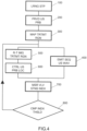
- Figure 4 details a method of treating valvular stenosis.
- the apparatus 1 comprises an ultrasound probe 2.
- the ultrasound probe 2 is located externally to a heart of a patient P and arranged to be able to produce ultrasound waves focused inside said patient P.
- the ultrasound probe 2 can be provided during a step 200 of the method illustrated on figure 4 .
- the ultrasound probe 2 comprises at least one ultrasound transducer 6 able to produced focused ultrasounds.
- the ultrasound probe 2 may further comprise a reflective cavity 9.
- the ultrasound transducer 6 can then be arranged to emit an emission signal inside the reflecting cavity 9 to generate a focused ultrasound wave inside the patient P.
- the ultrasound probe 2 can be arranged externally to the patient and, for instance, in contact with the skin S of the patient P, in particular close to the heart H of the patient P. This way, the method may be non-invasive.
- the ultrasound probe 2 may be introduced inside the oesophagus O of the patient P and brought in proximity with the heart H of the patient P.
- the skin and/or bones of the patient may be pushed aside during a preliminary surgical operation so that the ultrasound probe 2 can be arranged in closer proximity to the heart H.
- the ultrasound probe 2 may also be introduced under the skin and/or bones of the patient to be arranged in close proximity to the heart H. For instance a sternotomy may be performed and the ultrasound probe 2 may be brought in contact with the external wall of the heart of the patient.
- the apparatus 1 also comprises means 4 - e.g. an imaging device, and more particularly an ultrasonography (echography) probe - for mapping a treatment region R of a cardiac valve V of the patient P, the treatment region R comprising at least one leaflet L of the cardiac valve V.
- means 4 - e.g. an imaging device, and more particularly an ultrasonography (echography) probe - for mapping a treatment region R of a cardiac valve V of the patient P, the treatment region R comprising at least one leaflet L of the cardiac valve V.
- means 4 - e.g. an imaging device, and more particularly an ultrasonography (echography) probe - for mapping a treatment region R of a cardiac valve V of the patient P, the treatment region R comprising at least one leaflet L of the cardiac valve V.
- echography ultrasonography
- Said at least one leaflet L of the cardiac valve V may be calcified leaflet(s), in particular in the case of a method for treatment of valvular disease.
- the at least one leaflet L may also be stiff leaflet(s), for instance in the case of a method for preventing valvular disease.
- the treatment region R may also comprises at least one portion of an annulus of the cardiac valve, in particular a stiff or calcified portion of the annulus.
- the means for mapping 4 can be an ultrasound imaging array, and can, in particular, be the array of transducer 6 of the ultrasound probe 2 used for generating focused ultrasound waves, as illustrated on figure 2A .
- the means for mapping 4 may comprise an ultrasound imaging array 4 integrated in the ultrasound probe 2 and separated from the array of transducer 6 used for generating focused ultrasound waves.
- a central element 4 of the catheter ultrasound probe 2 comprises the ultrasound imaging array 4 of the means for mapping 4 and a surrounding element 6 comprises the array of transducer 6 used for generating focused ultrasound waves.
- the central element 4 has the shape of a disc but it may also present the shape of a rectangle or another suitable shape.
- the surrounding element 6 is shown with the shape of a circular annulus but may adopt other suitable shapes such as a rectangle ring or dots for instance.
- the surrounding element 6 may be divided in several elements, for instance several concentric rings 6 that can be independently controlled.
- the ultrasound imaging array 4 may acquire images in various imaging modes such as A-mode, B-mode, CW-Doppler, PW-Doppler, Color Doppler, Power Doppler, M-mode, Harmonic Imaging, Shear wave imaging, Elasticity Imaging, Tissue Strain Imaging, this list being not limitative.
- imaging modes such as A-mode, B-mode, CW-Doppler, PW-Doppler, Color Doppler, Power Doppler, M-mode, Harmonic Imaging, Shear wave imaging, Elasticity Imaging, Tissue Strain Imaging, this list being not limitative.
- the means for mapping 4 may comprises a CT scanning apparatus, an X-ray imaging apparatus or an MRI apparatus for instance.
- mapping it is meant that a digital image of the treatment region R is obtained during a mapping step 200.
- the digital image may for instance be stored in a memory.
- the digital image of the treatment region R may thus be obtained by ultrasound imaging, CT scanning, X-ray imaging or MRI, for instance.
- the treatment region R can cover a surface of at least 25 square millimetres, measured in a plane P perpendicular to an opening direction D of the cardiac valve V.
- opening direction it is meant a general direction D of the blood flowing through the cardiac valve V when said valve is open as illustrated on figure 1 .
- the apparatus 1 also comprises a controller 5 of the ultrasound probe 2.
- figure 3 illustrates a detail of the ultrasound probe 2 of figure 2 .
- the ultrasound transducers array 6 can comprise a few tens to a few hundred transducers 6.
- the array 6 may be a linear array, with the transducers arranged side by side along a longitudinal axis of the array.
- the array 6 can also be a two-dimensional array so as to emit three-dimensional focused waves.
- the controller 5 of the ultrasound probe 2 may then comprises for instance:
- the electronic system 7 may include for instance:
- the transducers T1-Tn are controlled independently of one another by the central processing unit.
- the controller 5 controls the ultrasound probe 2 to emit a sequence of N focused ultrasound waves.
- the ultrasound probe 2 emits focused ultrasound waves that generate negative pressure inside the tissues of the heart H of the patient P.
- the ultrasound probe 2 is controlled so that each focused ultrasound wave of the sequence of N focused ultrasound waves generates, at the focal spot, a pressure pulse sufficient to result in cavitation.
- a focal spot may be defined precisely as the volume wherein the ultrasound pressure exceeds the cavitation threshold.
- the resulting cavitation may form a bubble cloud at a focal spot of the focused ultrasound wave.
- acoustic cavitation occurs when the acoustic intensity or pressure exceeds a threshold of the tissue (cavitation threshold).
- the ultrasound probe 2 may for instance emit focused ultrasound waves that generate, at their focal spot, a peak negative pressure half-cycle that exceeds a peak negative pressure of 5 MPa, for instance present an absolute value higher than 10 MPa.
- the peak positive pressure half-cycle of the focused ultrasound waves may also exceeds a peak positive pressure of 10 MPa, for instance present an absolute value higher than 50 MPa.
- the duration of the pressure pulse generated by each focused ultrasound wave at the focal spot may be less than 80 microseconds, or even 20 microseconds.
- the duration of each focused ultrasound wave is less than 5 microseconds.
- the method of the disclosure and the apparatus of the invention thus prevent erosion and heating of the tissues of the heart and preserve structures surrounding the cardiac valves.
- the sequence of focused ultrasound waves is also such that the focal spots k of the sequence of N focused ultrasound waves scan the entire treatment region R.
- scan the entire treatment region it is meant that the centres of the focal spots k of the sequence of N focused ultrasound waves are arranged to fill the entire treatment region R with a given minimal distance separating the centre of each focal spots k and a given maximal distance separating the centre of each focal spots k from its nearest neighbour.
- each focal spots may be separated from its nearest neighbour by a given maximal distance of less than 1 millimetre.
- the centre of each focal spots of the sequence of focused ultrasound waves may be separated from one another by a minimal distance larger than 0.1 microns, for instance larger than 0.1 millimeter.
- some focused ultrasound waves of the sequence of focused ultrasound waves may present focal spots that have the same location inside the treatment region R.
- the focused ultrasound waves of the sequence of focused ultrasound waves may be periodically spaced or may be grouped on some predefined locations of the treatment region R.
- Figure 3 illustrates on example of the centres of the focal spots k of a sequence of N focused ultrasound waves.
- the order of emission of the sequence of N focused ultrasound waves is illustrated by dashed arrows connecting the centres of focal spots k as matter of non-limitative example.
- neighbouring focal spots may overlap; otherwise stated, the maximal distance between their centres may be smaller than their width. This ensures that all the points of the treatment region R (or of at least a connected subset thereof) are exposed at least once to ultrasound waves whose intensity is sufficient to induce cavitation.
- neighbouring focal spots may not overlap, their centres being separated by distances larger than their widths.
- only discrete locations of the treatment region R are exposed at least once to ultrasound waves whose intensity is sufficient to induce cavitation.
- An ultrasound probe 2 suited for emitting such high intensity controlled focused ultrasound waves is illustrated on figure 3 .
- the ultrasound probe 2 comprises a reflective cavity 9 and at least one transducer 6.
- the reflective cavity 9 may be filled with a liquid 10, for example water and in which the ultrasound transducers array 6 are located.
- the reflective cavity 9 comprises walls made of a material forming a highly reflective interface for acoustic waves, for example thin films separating the liquid contained in the cavity from the air outside the cavity.
- the reflective cavity 9 may be in contact at one of its ends with the patient P through a window 9a in the cavity wall, directly or through an acoustic lens 13 mounted on the window 9a.
- the reflective cavity 9 may further comprises a multi-scattering medium 11 adapted to be traversed by acoustic waves emitted by the ultrasound transducers before said waves reaches the patient's body.
- the multi-scattering medium 11 is able to cause multiple scattering of said acoustic waves.
- the multi-scattering medium 11 is located, for example, near the window 9a of the reflective cavity 9 and comprises a number of scatterers 12, for instance between several tens to several thousands of scatterers 12.
- the scatterers 12 are adapted to scatter acoustic waves and are advantageously distributed randomly or non-periodically in the multi-scattering medium 11, meaning that their distribution does not exhibit a periodic structure.
- the scatterers 8a may thus exhibit a surface having a significant difference in impedance compared to the medium of the reflective cavity.
- the scatterers 12 can have the general shape of vertical rods held in place by frames or attached to the walls of the reflective cavity.
- the scatterers 12 may take the form of beads, granules or cylinders and be held in place by foam, an elastomer, or three-dimensional frames so that they are distributed over all three dimensions of the space to form the multi-scattering medium 11.
- the scatterers 12 may, for example, have transverse cross-sections that are substantially between 0.1 and 5 times the wavelength of the wave in the reflective cavity, for example between 0.5 and 1 times said wavelength.
- Said transverse cross-section is understood to be a cross-section taken perpendicularly to the extension direction of the scatterers 12 and/or to the longest extension direction of the multi-scattering medium 11.
- the scatterers 12 can be distributed within the multi-scattering medium 11 so that their surface density in a cross-section of the multi-scattering medium 11 transverse to the extension direction Z of the scatterers 12, is, for an acoustic wave having a centre frequency of about 1 MHz, ten or so scatterers 12 per square centimetre, for example eighteen acoustic scatterers 12 per square centimetre.
- the scatterers 12 can be distributed in the multi-scattering medium 11 so that their volume packing density within the multi-scattering medium 11 is between 1% and 30%.
- the length of the multi-scattering medium 11, along the direction of propagation of the wave, may be a few centimetres, for example two centimetres.
- the array 6 of ultrasound transducers can be arranged on a face of the reflective cavity 9 facing the window open on the patient's body or may be oriented so as to emit waves toward the multi-scattering medium 11, at a certain angle relative to a cavity extension direction Y, for example 60°.
- Such a reflective cavity 9 forms a reverberator that permits, at the same time,
- a calibration 100, or learning step 100, of the ultrasound probe 2 may be conducted prior to performing the method of treatment.
- These individual emission signals are ultrasound signals that may be determined by calculation (for example using a spatio-temporal inverse filter method), or may be determined experimentally during a preliminary learning step 100.
- an ultrasonic pulse signal may be emitted by a hydrophone, successively placed at a succession of target points k in a volume of liquid placed in contact with the ultrasound probe 2.
- the signals r ik (t) received by each transducer i of the array 6 from the emission of said ultrasonic pulse signal are captured.
- the duration of the emission signal emitted by each transducer of the array 6 to generate a focused ultrasound wave of the sequence of focused ultrasound waves may be less than 10 milliseconds, in particular less than 1 millisecond.
- the duration of the pressure pulse generated by said focused ultrasound wave at the focal spot may be at least 10 times shorter, and preferably at least one hundred times shorter, than the duration of the emission signal emitted by each transducer of the array 6. Otherwise stated, the duration of the emission signal emitted by each transducer of the array 6 to generate a focused ultrasound wave of the sequence of focused ultrasound waves may be at least ten times longer than the duration of the pressure pulse generated by said focused ultrasound wave at the focal spot, preferably at least hundred times longer than the duration of said pressure pulse.
- the duration of the pressure pulse may be of less than 1 millisecond, preferably of less than 100 microseconds, even more preferably of less than 100 microsecond; for example, the emission signal may has a duration of the order of 800 microseconds and the pressure pulse at the focal point a duration of less than 5 microseconds.
- FIG. 5A to 5D illustrate different exemplary embodiments of such probes.
- the ultrasound probe 61 of figure 5A comprises an assembly of four reflective cavities 91, 92, 93, 94, each one similar to that of figure 3 , forming a square.
- An imaging array 4 is situated at the centre of the assembly.
- the reflective cavities are coupled to the patient's body through respective plastic bags filled with gel (not represented) while the imaging array 40 is almost directly in contact with it (in practice, with the interposition of a plastic sheet interconnecting the bags and of a thin layer of gel).
- the ultrasound probe of figure 5B comprises a multi-element transducer 62 consisting of a bi-dimensional array TA of several tens or hundreds of independently-driven elementary transducers (one of which is designated by reference IT).
- An imaging array 4 may be situated at the centre of the multi-element transducer, in order to be in direct - or almost direct - contact with the patient's body.
- This embodiment allows electronically steering the focused ultrasound waves, like the embodiments based on reflective cavities; its main drawback is the complexity of the controller 5, which has to comprise several tens or hundreds of independent power drivers for the individual elementary transducers.
- Figure 5C shows a much simpler ultrasound probe, based on a concave mono-element transducer 63, focusing ultrasound waves at a fixed depth.
- An imaging probe 4 is situated at the centre of the mono-element transducer.
- the focused ultrasound waves have to be mechanically steered, e.g. by displacing the transducer along three axes.
- a significant drawback is that, in order to allow a displacement of the transducer in the axial direction, the imaging array cannot be kept in direct contact with the body of the patient; imaging has then to be performed through a significant depth of matching gel, which reduces the quality of the acquired images.
- Figure 5D illustrates an annular array transducer 64, consisting of a limited number (typically 5 to 20, 10 in the example of the figures) of concentric ultrasound annular transducers 64a - 64j.
- Driving the annular transducers with an appropriate phase difference allows focusing an ultrasound wave at an adjustable depth.
- In-plane scanning is performed mechanically, by moving the transducer.
- Imaging probe 4 is situated at the centre of the innermost annular element.
- the complexity of the driver 5 is much lesser than in the case of figure 5B , due to the reduced number of power drivers; moreover, unlike the case of figure 5C , the imaging probe may be kept in contact with the patient's body, as the scanning in the axial direction is performed electronically.
- Document US 5,520,188 discloses an annular array transducer of this kind.
- An ultrasound probe suitable for the invention may be optimized to focus ultrasound energy in a predefined region, called a scannable region E illustrated on figure 3 .
- a scannable region E is a region of the patient body where the focusing of ultrasound energy by the ultrasound probe is more efficient and/or is calibrated.
- the scannable region E may be predefined during the preliminary learning step mentioned.
- the scannable region can for instance be defined by the succession of target points k where the hydrophone has been successively located during the preliminary learning step.
- the method according to the disclosure may also comprise a real-time imaging 500 of the cardiac valve, to map the treatment region.
- the step of real-time imaging of the cardiac valve may further allow to map the scannable region of the ultrasound probe.
- a mechanical control 600 of the location of the ultrasound probe externally to the heart of the patient may then be used to keep the treatment region inside the scannable region of the ultrasound probe.
- the ultrasound probe 2 can be mounted on a robotic arm 3, or holder, able to control the location of the ultrasound probe 2 with regard to the patient's heart H location.
- the robotic arm 3, driven by controller 5, may control the location of the ultrasound probe to keep the treatment region inside the scannable region of the ultrasound probe.
- the sequence of focused ultrasound waves is thus emitted at a predefined rate of emission while the focal spot of the focused ultrasound waves is moved to scan the entire treatment region R.
- the predefined rate of emission may be for instance comprised between 20 and 5000 shots per second, preferably between 50 and 1000 shots per second. In one example, the rate of emission may be about 100 shots per second. In another example it may be about 250 shots per second.
- the focal spot of the focused ultrasound waves may be moved to scan the entire treatment region with a predefined travelling speed.
- the predefined travelling speed may be comprised between 0.1 mm/s and 10 mm/s, preferably of the order of 1 mm/s.
- the focused ultrasound waves emitted by the ultrasound probe 2 can be steered to scan the entire treatment region R.
- the ultrasound probe 2 illustrated on figure 3 may be able to electronically steer the focused ultrasound waves to scan the entire treatment region R.
- the focused ultrasound waves are electronically steered, it is meant that the successive locations of the focal spots of the focused ultrasound waves are selected without physically moving the ultrasound probe 2, it this meant that the focal spot of focused ultrasound waves emitted by the ultrasound probe 2 can be moved without physically moving the ultrasound probe 2 but by controlling the emission signals of the transducers 6 of the ultrasound probe 2.
- the location of the ultrasound probe 2 may be mechanically controlled 600, e.g. using the robotic arm 3 or different mechanical actuators, in function of said motion of the treatment region, in order to scan the entire treatment region.
- Real-time imaging 500 may also be used to estimate a motion of the treatment region R with regard to the ultrasound probe 2; in the case of a heart valve, motion of the treatment region results mainly from a combination of breathing and hearth beat.
- the focused ultrasound waves emitted by the ultrasound probe 2 may then be steered in function of said motion of the treatment region, in order to scan the entire treatment region.
- real-time imaging 500 may allow performing real-time tracking of the valve to be treated.
- a tracking algorithm suitable to be used in the invention is discussed in the paper by R.M. Miller et al. "Histotripsy cardiac therapy system integrated with real-time motion correction", Ultrasound in Med. & Biol. Vol. 39, No.12 pp.2362 - 2373, 2013 .
- Another suitable tracking algorithm is described in M. Pernot et al. "3-D real-time motion correction in high-intensity focused ultrasound therapy” Ultrasound in Med Biol 2004, 30, 9, 1239-1249 .
- motions of the treatment region R can be compensated for by electronical steering of the focused ultrasound waves and/or mechanical control of the location of the ultrasound probe 2.
- the focused ultrasound wave emission may be driven by the following process, carried out by the controller 5:
- the controller 5 will be configured to perform the electronical and/or mechanical steering of the focused ultrasound waves in order to scan the target reason to be treated while tracking its motion during the treatment.
- tracking is used to keep ultrasound pulses focused on a same point of a heart.
- the successive insonification times and the cavitation locations may be computed to correspond to a travelling speed of the focal sport comprised between 0.1 mm/s and 10 mm/s, preferably of the order of 1 mm/s.
- the successive insonification times and the cavitation locations may be computed to correspond to alternate trajectory of the focal spot that may then correspond to a travelling speed of the focal sport higher than 10 mm/s.
- the centre of each focal spots of the sequence of N focused ultrasound waves may be separated from one another by a minimal distance shorter than a diameter (more generally, a width) of the focused ultrasound waves focal spots.
- a point of the treatment region may be included in the focal spots of several focused ultrasound waves, and each point of the treatment region is included in the focal spot of at least one focused ultrasound wave.
- the diameter of the focal spots of the focused ultrasound waves may be about 1 mm.
- the sequence of N focused ultrasound waves may be such that a point of the treatment region is included in the focal spots of a number M of focused ultrasound waves of the sequence of focused ultrasound waves, said number M being comprised between 1 and 1000, preferably between 2 and 1000, preferably of the order of 100.
- the centres of at least some focal spots of the sequence of N focused ultrasound waves may be separated from one another by a minimal distance longer than a diameter (more generally, a width) of the focused ultrasound waves focal spots. This way, at least some points of the treatment region may not be included in the focal spots of any focused ultrasound wave.
- the centre of each focal spots of the sequence of N focused ultrasound waves may be separated from one another by a minimal distance longer than a diameter (more generally, a width) of the focused ultrasound waves focal spots.
- the method according to the disclosure may also comprise a step of using a measuring device (which, in some embodiment, may be or include the imaging array 4 itself) for measuring an index of valvular stenosis 700 after having emitted the sequence of focused ultrasound waves.
- a measuring device which, in some embodiment, may be or include the imaging array 4 itself
- the index of valvular stenosis is a function of a hemodynamic parameter.
- the hemodynamic parameter may for instance be a heart pressure gradient across the cardiac heart valve or a blood flow velocity across the cardiac heart valve. These parameters may be measured using e.g. a Swan-Ganz catheter of a Millar catheter. However, use of such catheters is not preferred because it is invasive.
- performed hemodynamic parameter may be determined by using Doppler imaging to measure the blood flow velocity across the cardiac heart valve.
- Doppler imaging may be performed by a Doppler imager, which may include the imaging array 4, or a dedicated imaging device.
- the index of valvular stenosis can be function of a shear wave propagation parameter.
- the step of measuring the index of valvular stenosis may thus comprise a shear wave imaging step carried out using a shear wave imaging device, as described in document US-B2-7 252 004 for instance.
- the index of valvular stenosis may be function of a valve motion parameter.
- the step of measuring said index of valvular stenosis may then comprise an estimation of a valve motion, e.g. obtained by Doppler imaging.
- the index of valvular stenosis may then be compared 800 with a predefined threshold. This way, it is possible to assess the progress of the method.
- the predefined threshold may be representative of tissues softness to be achieved.
- At least the steps of controlling 400 the ultrasound probe to emit a sequence of N focused ultrasound waves and measuring 700 the index of valvular stenosis are reiterated until the index of valvular stenosis reaches, or crosses, the predefined threshold.
- N focused ultrasound waves may thus be emitted, separated by steps of control to assess the state of the cardiac heart valve tissues and its evolution.
- the exemplary method has been tested experimentally.
- PRF pulse repetition frequency
- 3D Echocardiography was used to guide and monitor the treatment.
- An IE33 (Philips TM ) scanner and X5-1 probe (xMATRIX TM array, 3 MHz, 3040 elements with microbeam-forming) were used.
- the imaging probe was fixed through a hole in the center of the therapy transducer.
- the focal spot of the therapy transducer was positioned on the central axis of the imaging probe at a depth of 100mm.
- a bi-plane imaging mode with two imaging planes set at 90° was used during the whole procedure.
- the histotripsy focal spot was visible within the two imaging planes.
- the combination of therapy transducer and imaging probe was called the "therapy device".
- the same material was used for in vitro and in vivo procedures.
- sequences of 10 minutes of ultrasound waves were applied, and repeated until reaching a stabilization of the transvalvular gradient for 3 consecutive sequences.
- the therapy device was controlled by a 3-axis motor for scanning the ultrasounds continuously and uniformly over the entire valve.
- shear wave elastography an ultrasound-based tool for noninvasive evaluation of soft tissue's stiffness.
- the Aixplorer ultrasound imaging system (Aixplorer TM , Supersonic Imagine, Aix-en-speaking, France) with a linear probe (SL10-2) was used to evaluate the stiffness of each valvular leaflet.
- Three acquisitions were made for each leaflet, using the shear wave elastography imaging mode (SWE TM ) of the Aixplorer scanner in the 'penetration' setting.
- a ''QBox TM '' region of interest (mean diameter 1 mm) was positioned inside the elasticity image after each acquisition to obtain a mean stiffness value.
- FIG. 6 The setup of the in vitro procedure is illustrated on figure 6 .
- a bioprothesis A is placed right in front to the therapy device B, including transducer 6 and imaging probe 4, both immersed in degassed water.
- a three-axes motor 3AM was used to adjust the position of the therapy device 6.
- An artificial cardiac pump C Harmonic Apparatus Pulsatile Blood Pump ®
- the flow rates were applied at 3L, 4L and 5L per minute, monitored by a flow sensor D (Small flow Meter Kit, Atlas scientific ® ; accuracy +/- 1 ml/min). water.
- the transvalvular pressure gradient was estimated by:
- the pump operated during 2 hours at 4L / min flow rate (70 cycles per minute, ejection volume equal to 57 mL) to control the variation of the gradient before carrying out the exemplary method, after which sequences of ultrasound focused waves were applied.
- bioprostheses explanted on humans were implanted on sheep.
- the implantation was performed in mitral position, and not in aortic position, because of the relative diameters of the implanted valves and of the sheep's aortic valves (diameter between 8 and 16 mm).
- the inventors consider that the mitral implantation was acceptable to determinate if the application of focused ultrasound waves could decrease the calcified stenosis.
- the setup is illustrated on figure 7 .
- the sheep were anesthetized with thiopentothal (0.5 mL/kg), intubated, ventilated at 15 mL/kg with 2% isoflurane, and given glycopyrrolate (0.4 mg intravenous) and vancomycin (0.5 grams intravenous). A sterile sternotomy was performed. The calcified bioprosthesis was implanted in mitral position, after CPB.
- Vital signs including heart rate (HR), oxygen saturation, arterial blood pressure (BP)), left atrial and ventricle pressure (by two Mikro-Tip ® Millar Catheter Transducers MC , to have the transvalvular pressure gradient in real time) and cardiac flow (by a Swan-Ganz CCOmbo Pulmonary Artery Catheter, Edwards Lifesciences ® , reference SG) were monitored.
- the CPB was stopped and removed to restore independent cardiac activity.
- Sternotomy was maintained and the thorax was filled with degassed saline water.
- a completed echocardiography was realized, especially to evaluate the calcified bioprosthesis.
- the therapy device B was immersed in the water filling the thorax and positioned near the heart H (RA: right atrium, LA: left atrium; RV: right ventricle; LV: left ventricle) with the help of a three-axis motor 3AM in order to apply several sequences of focused ultrasound waves onto the implanted bioprothesis A.
- An echocardiographic evaluation was realized between each sequence, in parallel of the catheters evaluation (pressure and cardiac flow).
- the animal was sacrificed (Dolethal TM intravenous injection, 1 ml/kg) and an anatomical macroscopic evaluation of the cardiac structure was performed. The bioprosthesis was then explanted and sent after elastography to the department of pathology for histopathological analysis.
- bioprosthesis were dissected, fixed in formalin and embedded in individual paraffin blocks. Regions of interest, like macroscopic calcification on leaflet, were labeled with tattoo ink. Serial sections were stained with H&E (hematoxylin and eosin) for histopathological analysis.
- H&E hematoxylin and eosin
- bioprostheses were also sent for histopathological analysis directly after their explantation from human, without any application of ultrasound. The objective was to allow a histopathological comparison between bioprostheses with or without treatement.
- Hemodynamic parameters were also measured at 3L/min and at 5L/min, before and after procedure, and the gradients also showed a significant decrease (p ⁇ 0.01).
- the mean gradient varies from 14.2 ⁇ 2.5 to 7.1 ⁇ 1.2 mmHg (p ⁇ 0.01) and the maximum gradient from 29.1 ⁇ 5.1 to 14.9 ⁇ 2.6 mmHg (p ⁇ 0.01).
- the mean gradient varies from 23.8 ⁇ 4.2 to 13 ⁇ 2.3 mmHg (p ⁇ 0.01) and the maximum gradient from 42.3 ⁇ 7.5 to 24.1 ⁇ 4.3 mmHg (p ⁇ 0.01).
- Figure 9 shows mean transvalvular gradient results for each valve treated in vitro.
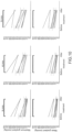
- Figure 10 shows multi flow results (3L, 4L and 5L/min) obtained in vitro for each valve.
- the mean duration of procedure was 60 ⁇ 13 minutes with a maximum duration of 100 minutes and a minimum of 40 minutes. An important decrease of the transvalvular gradient was observed after treatment (see table 1).
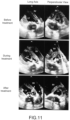
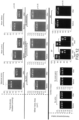
- Figure 11 shows echocardiography images acquired before, during and after the treatment.
- the "cloud of cavitation" microbubble
- the modification of the bioprothesis opening is confirmed by echocardiography (see the arrow on the lowest-leftmost image of the figure).
- VES Isolated ventricular extrasystols
- the mean stiffness of the valves leaflets measured by elastography was 105.8 ⁇ 9 kPa.
- the mean stiffness of valves leaflets measured by elastography was 46.6 ⁇ 4 kPa. It corresponds to a decrease of 55 ⁇ 8% (p ⁇ 0.01).
- FIG. 13 shows exemplary Shear Wave Elastography images acquired in vitro to measure mean stiffness.
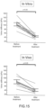
- Figure 14 shows numerical results obtained in vitro (upper panel) and in vivo (lower panel). Stiffness results for each individual bioprosthesis are shown on figure 15 .
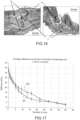
- Figure 16 shows histological images of a treated bioprothesis. All the superficial structures of the leaflets (fibrosa and ventricularis) were intact - see reference S. In comparison with the five bioprostheses explanted without application of the procedure, it was possible to observe:
- An alternative or complementary solution would be to trigger histotripsy exposures by electrocardiogram. Indeed, it is possible to select specific moments in the cardiac cycle for example during the refractory period of the myocardium (to avoid inducing extrasystoles) or when the aortic valve is closed and thus its whole surface is equally exposed, and far away from the cardiac wall.
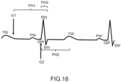
- Figure 18 is a simplified representation of an electrocardiographic trace; references TW, PW, QW, RW, SW correspond to T-waves, P-waves, Q-waves, R-waves and S-waves respectively; G1 and G2 correspond to suitable gating time, i.e. start times for ultrasound pulses; PH1, PH2 and PH3 identify time periods during which ultrasound pulses may be applied with optimal safety and/or effectiveness.
- the first period, PH1 starts at G1, after the T-wave, and ends after the R-wave; it has duration of about 650 ms. It corresponds to the period when the aortic valve is closed.
- the second period, PH2 starts at G2 (i.e. on the R-wave) and ends at the T-wave; it has duration of about 250 ms. It corresponds to a refractory period of the heart, where the risk of inducing extrasystoles is minimal, and therefore safety is maximal.
- the third period, PH3, is the intersection of PH1 and PH2. It starts at G2 and has duration of about 30 ms. It corresponds to optimal conditions: the aortic valve is closed, and the hearth is in its refractory period. Its main drawback is its short duration (30 ms/cycle).
Landscapes
- Health & Medical Sciences (AREA)
- Life Sciences & Earth Sciences (AREA)
- Engineering & Computer Science (AREA)
- Veterinary Medicine (AREA)
- Public Health (AREA)
- Biomedical Technology (AREA)
- General Health & Medical Sciences (AREA)
- Animal Behavior & Ethology (AREA)
- Nuclear Medicine, Radiotherapy & Molecular Imaging (AREA)
- Radiology & Medical Imaging (AREA)
- Surgery (AREA)
- Medical Informatics (AREA)
- Molecular Biology (AREA)
- Heart & Thoracic Surgery (AREA)
- Physics & Mathematics (AREA)
- Pathology (AREA)
- Biophysics (AREA)
- Cardiology (AREA)
- Hematology (AREA)
- Robotics (AREA)
- Gynecology & Obstetrics (AREA)
- Surgical Instruments (AREA)
- Ultra Sonic Daignosis Equipment (AREA)
Claims (14)
- Appareil de traitement ou de prévention d'une sténose valvulaire, l'appareil comprenant :- une sonde à ultrasons (2, 6) située à l'extérieur d'un cœur (H) d'un patient (P), apte à produire des ondes ultrasonores focalisées à l'intérieur dudit cœur (H) et appropriée pour générer, au niveau d'un point focal, une pression suffisante pour entraîner une cavitation,- un dispositif d'imagerie (4) pour représenter en temps réel une région de traitement (A, C) d'une valvule cardiaque du patient, ladite région de traitement comprenant au moins un feuillet de la valvule cardiaque,- un dispositif de commande (5, 7, 8) configuré pour conduire la sonde à ultrasons à émettre une séquence d'ondes ultrasonores focalisées,le dispositif de commande étant en outre configuré pour estimer en temps réel un mouvement de la région de traitement à partir d'images acquises par ledit dispositif d'imagerie, et pour diriger les ondes ultrasonores focalisées émises par la sonde à ultrasons en fonction dudit mouvement de la région de traitement pour balayer la région de traitement entière,caractérisé en ce que l'appareil comprend en outre un dispositif de mesure approprié pour mesurer un indice de sténose valvulaire après que la sonde à ultrasons est commandée pour émettre la séquence de N ondes ultrasonores focalisées, le dispositif de commande étant en outre configuré pour répéter les étapes de commande de la sonde à ultrasons pour émettre une séquence d'ondes ultrasonores focalisées et de mesure dudit indice de sténose valvulaire jusqu'à ce que ledit indice franchisse un seuil prédéfini.
- Appareil selon la revendication 1, comprenant un outre un bras robotique (3) portant ladite sonde à ultrasons, le dispositif de commande étant configuré pour conduire le bras robotique à commander la position de la sonde à ultrasons à l'extérieur du cœur du patient de façon à maintenir la région de traitement à l'intérieur d'une région pouvant être balayée par la sonde à ultrasons.
- Appareil selon l'une quelconque des revendications précédentes, dans lequel ledit dispositif de mesure est un imageur Doppler configuré pour mesurer un paramètre hémodynamique, ledit indice de sténose valvulaire étant une fonction dudit paramètre hémodynamique.
- Appareil selon l'une quelconque des revendications précédentes, dans lequel ledit dispositif de mesure est un dispositif d'imagerie configuré pour détecter et estimer un paramètre de mouvement de valvule, ledit indice de sténose valvulaire étant une fonction dudit paramètre de mouvement de valvule.
- Appareil selon l'une quelconque des revendications précédentes, dans lequel ledit dispositif de mesure est un imageur d'ondes de cisaillement configuré pour mesurer un paramètre de propagation d'ondes de cisaillement, ledit indice de sténose valvulaire étant une fonction dudit paramètre de propagation d'ondes de cisaillement.
- Appareil selon l'une quelconque des revendications précédentes, dans lequel le dispositif de commande est configuré pour conduire la sonde à ultrasons à émettre ladite séquence d'ondes ultrasonores focalisées à une cadence entre 20 et 5000 tirs par seconde.
- Appareil selon l'une quelconque des revendications précédentes, dans lequel le dispositif de commande est configuré pour diriger les ondes ultrasonores focalisées de façon à déplacer leur point focal à une vitesse de translation comprise entre 0,1 mm/s et 10 mm/s.
- Appareil selon l'une quelconque des revendications précédentes, dans lequel le dispositif de commande est configuré pour diriger les ondes ultrasonores focalisées de sorte qu'un point de la région de traitement soit inclus dans les points focaux d'un nombre M d'ondes ultrasonores focalisées de la séquence d'ondes ultrasonores focalisées, ledit nombre M étant compris entre 1 et 1000, de préférence entre 2 et 1000, et de manière plus préférée entre 15 et 150.
- Appareil selon l'une quelconque des revendications précédentes, dans lequel le dispositif de commande est configuré pour diriger les ondes ultrasonores focalisées de façon à ce que les points focaux de la séquence d'ondes ultrasonores focalisées soient séparés d'une distance minimale supérieure à 0,1 millimètre.
- Appareil selon l'une quelconque des revendications précédentes, dans lequel le dispositif de commande est configuré pour entraîner la sonde à ultrasons de telle sorte qu'une durée d'une impulsion de pression générée par chaque onde ultrasonore focalisée de la séquence d'ondes ultrasonores focalisées soit inférieure à 80 microsecondes, de préférence inférieure à 20 microsecondes.
- Appareil selon l'une quelconque des revendications précédentes, dans lequel la sonde à ultrasons comprend une pluralité de transducteurs (6) dans une cavité réfléchissante (9), et dans lequel le dispositif de commande est configuré pour conduire au moins un dit transducteur à émettre un signal d'émission dans la cavité réfléchissante, la durée dudit signal d'émission étant inférieure à 10 millisecondes, de préférence inférieure à 1 milliseconde.
- Appareil selon la revendication 11, dans lequel la durée du signal d'émission émis par ledit au moins un transducteur pour générer ladite onde ultrasonore focalisée est au moins dix fois plus longue que la durée d'une impulsion de pression générée par ladite onde ultrasonore focalisée au niveau d'un point focal, de préférence au moins cent fois plus longue que ladite durée de ladite impulsion de pression.
- Appareil selon l'une quelconque des revendications précédentes, dans lequel le dispositif de commande est configuré pour conduire la sonde à ultrasons à émettre lesdites ondes ultrasonores focalisées de sorte que chacune d'entre elles génère au niveau d'un point focal un demi-cycle de pression de pointe négative qui dépasse une pression de pointe négative de 5 MPa et/ou un demi-cycle de pression de pointe positive qui dépasse une pression de pointe positive de 10 MPa.
- Appareil selon l'une quelconque des revendications précédentes, dans lequel le dispositif de commande est configuré en outre pour recevoir un signal d'électrocardiographie et pour conduire la sonde à ultrasons à émettre la séquence d'ondes ultrasonores focalisées durant des moments spécifiques dans un cycle cardiaque, déterminées à partir dudit signal d'électrocardiographie.
Applications Claiming Priority (2)
| Application Number | Priority Date | Filing Date | Title |
|---|---|---|---|
| US201562142096P | 2015-04-02 | 2015-04-02 | |
| PCT/IB2016/000523 WO2016156989A1 (fr) | 2015-04-02 | 2016-04-01 | Procédé et appareil pour le traitement d'une valvulopathie |
Publications (3)
| Publication Number | Publication Date |
|---|---|
| EP3277378A1 EP3277378A1 (fr) | 2018-02-07 |
| EP3277378B1 true EP3277378B1 (fr) | 2025-05-21 |
| EP3277378C0 EP3277378C0 (fr) | 2025-05-21 |
Family
ID=55967332
Family Applications (1)
| Application Number | Title | Priority Date | Filing Date |
|---|---|---|---|
| EP16722358.5A Active EP3277378B1 (fr) | 2015-04-02 | 2016-04-01 | Appareil pour le traitement d'une valvulopathie |
Country Status (9)
| Country | Link |
|---|---|
| US (1) | US10736603B2 (fr) |
| EP (1) | EP3277378B1 (fr) |
| JP (1) | JP6727286B2 (fr) |
| KR (1) | KR102574559B1 (fr) |
| CN (1) | CN107660137B (fr) |
| CA (1) | CA2981219C (fr) |
| IL (1) | IL254768B (fr) |
| SG (1) | SG11201707443YA (fr) |
| WO (1) | WO2016156989A1 (fr) |
Cited By (3)
| Publication number | Priority date | Publication date | Assignee | Title |
|---|---|---|---|---|
| US12491384B2 (en) | 2018-11-28 | 2025-12-09 | Histosonics, Inc. | Histotripsy systems and methods |
| US12527976B2 (en) | 2020-06-18 | 2026-01-20 | Histosonics, Inc. | Histotripsy acoustic and patient coupling systems and methods |
| US12582848B2 (en) | 2021-06-07 | 2026-03-24 | The Regents Of The University Of Michigan | Minimally invasive histotripsy systems and methods |
Families Citing this family (37)
| Publication number | Priority date | Publication date | Assignee | Title |
|---|---|---|---|---|
| CA2981219C (fr) * | 2015-04-02 | 2024-01-23 | Cardiawave | Procede et appareil pour le traitement d'une valvulopathie |
| EP4230262A3 (fr) | 2015-06-24 | 2023-11-22 | The Regents Of The University Of Michigan | Systèmes de thérapie par histotripsie pour le traitement de tissu cérébral |
| WO2018098091A1 (fr) * | 2016-11-22 | 2018-05-31 | Cedars-Sinai Medical Center | Nouveau dispositif d'administration de médicament et de transfection |
| ES2774069T3 (es) | 2017-02-17 | 2020-07-16 | Cardiawave | Sistema para la insonificación segura de tejidos vivos |
| JP6968576B2 (ja) * | 2017-05-29 | 2021-11-17 | キヤノンメディカルシステムズ株式会社 | 超音波診断装置及び超音波診断支援装置 |
| CN110404187B (zh) * | 2018-04-28 | 2022-03-01 | 重庆海扶医疗科技股份有限公司 | 产生超高声压的方法、超高声压产生装置 |
| KR102128033B1 (ko) | 2018-05-03 | 2020-06-29 | 울산대학교 산학협력단 | 이첨판막의 판막륜 크기 결정 방법 |
| FR3081334B1 (fr) * | 2018-05-25 | 2020-05-01 | Cardiawave Sa | Appareil de traitement par ultrasons comportant des moyens d'imagerie des bulles de cavitation |
| CN108836471A (zh) * | 2018-08-20 | 2018-11-20 | 安徽声达愈医疗器械有限公司 | 聚焦超声治疗装置 |
| JP7258538B2 (ja) * | 2018-12-14 | 2023-04-17 | キヤノンメディカルシステムズ株式会社 | 超音波診断装置、医用情報処理装置、医用情報処理プログラム |
| CN109498406A (zh) * | 2019-01-09 | 2019-03-22 | 珠海泓韵科技有限公司 | 一种便携式相控阵超声波美容仪 |
| CN110215234B (zh) * | 2019-06-05 | 2024-04-02 | 瀚维(台州)智能医疗科技股份有限公司 | 超声扫描检查的扫描运动系统 |
| EP3986548A1 (fr) | 2019-06-19 | 2022-04-27 | Theraclion SA | Dispositif et méthode de traitement d'un patient par ultrasons focalisés à haute intensité (hifu) |
| FR3099357B1 (fr) * | 2019-08-01 | 2021-08-20 | Institut National De Rech En Informatique Et En Automatique Inria | Dispositif cardiaque |
| US12376824B2 (en) * | 2019-10-21 | 2025-08-05 | University Of Virginia Patent Foundation | Methods, systems, and computer readable media for utilizing a therapeutic ultrasound device to perform mitral valve decalcification |
| AU2021206666A1 (en) * | 2020-01-07 | 2022-07-21 | The Regents Of The University Of Michigan | Systems and methods for robotically-assisted histotripsy targeting based on MRI/CT scans taken prior to treatment |
| WO2021155026A1 (fr) | 2020-01-28 | 2021-08-05 | The Regents Of The University Of Michigan | Systèmes et procédés d'immunosensibilisation par histotripsie |
| CA3172379A1 (fr) * | 2020-03-06 | 2021-09-10 | Histosonics, Inc. | Systemes et procedes d'histotripsie minimalement invasifs |
| CN111408075B (zh) * | 2020-03-23 | 2022-08-30 | 南京广慈医疗科技有限公司 | 一种带测温功能的高强度聚焦超声诊疗系统及其控制方法 |
| SG10202003167YA (en) * | 2020-04-06 | 2021-11-29 | Ultrasound Assisted Medtech Pte Ltd | High intensity focused ultrasound (hifu) probe |
| CN111374740B (zh) * | 2020-04-22 | 2021-10-08 | 重庆市江津区中心医院 | 一种房间隔穿刺术用增强现实辅助穿刺系统 |
| CN111493935B (zh) * | 2020-04-29 | 2021-01-15 | 中国人民解放军总医院 | 基于人工智能的超声心动图自动预测识别方法及系统 |
| IL274382A (en) * | 2020-05-01 | 2021-12-01 | Pulsenmore Ltd | A system and method for assisting an unskilled patient in performing ultrasound scans himself |
| EP4204084A4 (fr) | 2020-08-27 | 2024-10-09 | The Regents Of The University Of Michigan | Transducteur ultrasonore à capacité d'émission-réception pour l'histotripsie |
| IL308943A (en) | 2021-06-07 | 2024-01-01 | Univ Michigan Regents | All-inclusive ultrasound systems and methods that include histotripsy |
| WO2023002227A1 (fr) * | 2021-07-19 | 2023-01-26 | Institut National De La Sante Et De La Recherche Medicale (Inserm) | Procédés et systèmes de modification de propriétés d'élasticité d'une cible dans un matériau souple |
| CN115670513A (zh) * | 2021-07-23 | 2023-02-03 | 深圳迈瑞生物医疗电子股份有限公司 | 基于超声的血流测量方法和超声成像系统 |
| CN113796992A (zh) * | 2021-09-26 | 2021-12-17 | 上海市同济医院 | 一种基于图像分割的自动化瓣膜支架输送系统 |
| CN114376603B (zh) * | 2022-01-07 | 2023-11-28 | 乐普(北京)医疗器械股份有限公司 | 一种二维频谱多普勒超声心动图像的处理方法和装置 |
| DE102022200740B3 (de) * | 2022-01-24 | 2023-01-26 | Siemens Healthcare Gmbh | Therapievorrichtung zur Ultraschallbehandlung |
| AU2023366591A1 (en) * | 2022-10-28 | 2025-04-24 | Histosonics, Inc. | Histotripsy systems and methods |
| EP4445859A1 (fr) * | 2023-04-12 | 2024-10-16 | Commissariat à l'Energie Atomique et aux Energies Alternatives | Sonication à ultrasons focalisés avec orientation mécanique et électronique le long d'une trajectoire calculée |
| WO2024221001A2 (fr) | 2023-04-20 | 2024-10-24 | Histosonics, Inc. | Systèmes d'histotripsie et procédés associés comprenant des interfaces utilisateur et des flux de travail pour la planification et la thérapie de traitement |
| EP4574206A1 (fr) | 2023-12-22 | 2025-06-25 | Cardiawave | Procédé de détection de cavitation |
| US12402901B2 (en) | 2024-02-08 | 2025-09-02 | IV-X Medical, LLC | Intravascular lithotripsy catheter |
| WO2025214807A1 (fr) * | 2024-04-10 | 2025-10-16 | Koninklijke Philips N.V. | Système de diagnostic médical et thérapeutique à ultrasons |
| CN119818239B (zh) * | 2025-03-05 | 2026-02-17 | 西安交通大学 | 一种用于人工瓣膜的输送系统 |
Citations (4)
| Publication number | Priority date | Publication date | Assignee | Title |
|---|---|---|---|---|
| US20040082910A1 (en) * | 2002-10-29 | 2004-04-29 | Constantz Brent R. | Devices and methods for treating aortic valve stenosis |
| US20050252295A1 (en) * | 2002-09-02 | 2005-11-17 | Centre National De La Recherche Scientifique- Cnrs | Imaging method and device employing sherar waves |
| US20100036253A1 (en) * | 2008-08-05 | 2010-02-11 | Daniel Vezina | System and method for managing a patient |
| US20140142494A1 (en) * | 2009-10-06 | 2014-05-22 | Michael P. Wallace | Methods and devices for endovascular therapy |
Family Cites Families (33)
| Publication number | Priority date | Publication date | Assignee | Title |
|---|---|---|---|---|
| DE3417710A1 (de) * | 1984-05-12 | 1985-11-14 | Dornier System Gmbh, 7990 Friedrichshafen | Applikationsschablone |
| US4693247A (en) * | 1986-09-29 | 1987-09-15 | Trutek Research, Inc. | Triggering circuit |
| US5188106A (en) | 1991-03-08 | 1993-02-23 | Telectronics Pacing Systems, Inc. | Method and apparatus for chronically monitoring the hemodynamic state of a patient using doppler ultrasound |
| US6522905B2 (en) * | 1993-03-11 | 2003-02-18 | Jawahar M. Desai | Apparatus and method for cardiac ablation |
| US5520188A (en) | 1994-11-02 | 1996-05-28 | Focus Surgery Inc. | Annular array transducer |
| US7686763B2 (en) * | 1998-09-18 | 2010-03-30 | University Of Washington | Use of contrast agents to increase the effectiveness of high intensity focused ultrasound therapy |
| US6425867B1 (en) * | 1998-09-18 | 2002-07-30 | University Of Washington | Noise-free real time ultrasonic imaging of a treatment site undergoing high intensity focused ultrasound therapy |
| WO2001000114A1 (fr) * | 1999-06-25 | 2001-01-04 | Vahid Saadat | Appareil et techniques permettant de traiter des tissus |
| US7244230B2 (en) * | 2002-11-08 | 2007-07-17 | Siemens Medical Solutions Usa, Inc. | Computer aided diagnostic assistance for medical imaging |
| WO2004075987A1 (fr) * | 2003-02-28 | 2004-09-10 | Koninklijke Philips Electronics, N.V. | Perfectionnements apportes au suivi du mouvement pour traitement par ultrasons focalises de haute intensite |
| US7344509B2 (en) | 2003-04-17 | 2008-03-18 | Kullervo Hynynen | Shear mode therapeutic ultrasound |
| US7311701B2 (en) | 2003-06-10 | 2007-12-25 | Cierra, Inc. | Methods and apparatus for non-invasively treating atrial fibrillation using high intensity focused ultrasound |
| US20050149008A1 (en) * | 2003-09-04 | 2005-07-07 | Crum, Kaminski & Larson, Llc | Treatment of cardiac arrhythmia utilizing ultrasound |
| CA2439667A1 (fr) * | 2003-09-04 | 2005-03-04 | Andrew Kenneth Hoffmann | Systeme et appareil de perfusion sanguine assistes d'un dispositif produisant des vibrations a basse frequence |
| US20050209588A1 (en) * | 2003-09-04 | 2005-09-22 | Crum, Kaminski & Larson, Llc | HIFU resculpturing and remodeling of heart valves |
| US20060025683A1 (en) * | 2004-07-30 | 2006-02-02 | Ahof Biophysical Systems Inc. | Hand-held imaging probe for treatment of states of low blood perfusion |
| US7591996B2 (en) * | 2005-08-17 | 2009-09-22 | University Of Washington | Ultrasound target vessel occlusion using microbubbles |
| JP4192184B2 (ja) | 2006-03-20 | 2008-12-03 | 株式会社東芝 | 超音波治療装置 |
| JP2008073423A (ja) | 2006-09-25 | 2008-04-03 | Toshiba Corp | 超音波診断装置、診断パラメータ計測装置及び診断パラメータ計測方法 |
| US20080154131A1 (en) * | 2006-12-20 | 2008-06-26 | General Electric Company | Methods for enhancement of visibility of ablation regions |
| WO2008086434A2 (fr) | 2007-01-09 | 2008-07-17 | Cyberheart, Inc. | Dépôt de rayonnement dans le myocarde sous guidage échographique |
| US20080253527A1 (en) * | 2007-04-11 | 2008-10-16 | Searete Llc, A Limited Liability Corporation Of The State Of Delaware | Limiting compton scattered x-ray visualizing, imaging, or information providing at particular regions |
| US8428690B2 (en) * | 2007-05-16 | 2013-04-23 | General Electric Company | Intracardiac echocardiography image reconstruction in combination with position tracking system |
| PL390174A1 (pl) * | 2007-06-25 | 2010-07-05 | International Cardio Corporationinternational Cardio Corporation | Ablacja płytek z wykorzystaniem techniki obrazowania |
| US8251908B2 (en) * | 2007-10-01 | 2012-08-28 | Insightec Ltd. | Motion compensated image-guided focused ultrasound therapy system |
| EP2208182B1 (fr) * | 2007-11-14 | 2011-06-08 | Koninklijke Philips Electronics N.V. | Système et procédé pour une analyse ceus en 3d quantitative |
| WO2009081339A1 (fr) * | 2007-12-21 | 2009-07-02 | Koninklijke Philips Electronics, N.V. | Systèmes et procédés pour suivre et guider des faisceaux ultrasoniques focalisés haute intensité |
| US20090198093A1 (en) * | 2008-02-06 | 2009-08-06 | Oliver Meissner | System and method for combined embolization and ablation therapy |
| EP2785256A4 (fr) | 2011-12-01 | 2016-03-30 | Neochord Inc | Navigation chirurgicale pour la réparation de valvules cardiaques |
| US20130296743A1 (en) * | 2012-05-02 | 2013-11-07 | Siemens Medical Solutions Usa, Inc. | Ultrasound for Therapy Control or Monitoring |
| FR2991807B1 (fr) * | 2012-06-06 | 2014-08-29 | Centre Nat Rech Scient | Dispositif et procede de focalisation d'impulsions |
| US9510802B2 (en) * | 2012-09-21 | 2016-12-06 | Guided Therapy Systems, Llc | Reflective ultrasound technology for dermatological treatments |
| CA2981219C (fr) * | 2015-04-02 | 2024-01-23 | Cardiawave | Procede et appareil pour le traitement d'une valvulopathie |
-
2016
- 2016-04-01 CA CA2981219A patent/CA2981219C/fr active Active
- 2016-04-01 CN CN201680031056.0A patent/CN107660137B/zh active Active
- 2016-04-01 KR KR1020177031325A patent/KR102574559B1/ko active Active
- 2016-04-01 JP JP2018502839A patent/JP6727286B2/ja active Active
- 2016-04-01 WO PCT/IB2016/000523 patent/WO2016156989A1/fr not_active Ceased
- 2016-04-01 SG SG11201707443YA patent/SG11201707443YA/en unknown
- 2016-04-01 US US15/557,455 patent/US10736603B2/en active Active
- 2016-04-01 EP EP16722358.5A patent/EP3277378B1/fr active Active
-
2017
- 2017-09-28 IL IL254768A patent/IL254768B/en active IP Right Grant
Patent Citations (4)
| Publication number | Priority date | Publication date | Assignee | Title |
|---|---|---|---|---|
| US20050252295A1 (en) * | 2002-09-02 | 2005-11-17 | Centre National De La Recherche Scientifique- Cnrs | Imaging method and device employing sherar waves |
| US20040082910A1 (en) * | 2002-10-29 | 2004-04-29 | Constantz Brent R. | Devices and methods for treating aortic valve stenosis |
| US20100036253A1 (en) * | 2008-08-05 | 2010-02-11 | Daniel Vezina | System and method for managing a patient |
| US20140142494A1 (en) * | 2009-10-06 | 2014-05-22 | Michael P. Wallace | Methods and devices for endovascular therapy |
Cited By (6)
| Publication number | Priority date | Publication date | Assignee | Title |
|---|---|---|---|---|
| US12491384B2 (en) | 2018-11-28 | 2025-12-09 | Histosonics, Inc. | Histotripsy systems and methods |
| US12491382B2 (en) | 2018-11-28 | 2025-12-09 | Histosonics, Inc. | Histotripsy systems and methods |
| US12589261B2 (en) | 2018-11-28 | 2026-03-31 | Histosonics, Inc. | Histotripsy systems and methods |
| US12599784B2 (en) | 2018-11-28 | 2026-04-14 | Histosonics, Inc. | Histotripsy systems and methods |
| US12527976B2 (en) | 2020-06-18 | 2026-01-20 | Histosonics, Inc. | Histotripsy acoustic and patient coupling systems and methods |
| US12582848B2 (en) | 2021-06-07 | 2026-03-24 | The Regents Of The University Of Michigan | Minimally invasive histotripsy systems and methods |
Also Published As
| Publication number | Publication date |
|---|---|
| IL254768B (en) | 2021-05-31 |
| CN107660137A (zh) | 2018-02-02 |
| EP3277378A1 (fr) | 2018-02-07 |
| US10736603B2 (en) | 2020-08-11 |
| US20180064412A1 (en) | 2018-03-08 |
| IL254768A0 (en) | 2017-12-31 |
| KR102574559B1 (ko) | 2023-09-05 |
| CA2981219A1 (fr) | 2016-10-06 |
| SG11201707443YA (en) | 2017-10-30 |
| CN107660137B (zh) | 2020-10-09 |
| JP2018512251A (ja) | 2018-05-17 |
| KR20170134548A (ko) | 2017-12-06 |
| JP6727286B2 (ja) | 2020-07-22 |
| CA2981219C (fr) | 2024-01-23 |
| WO2016156989A1 (fr) | 2016-10-06 |
| EP3277378C0 (fr) | 2025-05-21 |
Similar Documents
| Publication | Publication Date | Title |
|---|---|---|
| EP3277378B1 (fr) | Appareil pour le traitement d'une valvulopathie | |
| US20230128189A1 (en) | Ultrasound guided opening of blood-brain barrier | |
| Marquet et al. | Non-invasive transcranial ultrasound therapy based on a 3D CT scan: protocol validation and in vitro results | |
| US6846290B2 (en) | Ultrasound method and system | |
| EP3723854B1 (fr) | Focalisation d'ondes ultrasonores dans des médias changeant dynamiquement | |
| Child et al. | Lung damage from exposure to pulsed ultrasound | |
| Gateau et al. | In vivo bubble nucleation probability in sheep brain tissue | |
| EP3363498B1 (fr) | Dispositif pour insonification assurée de tissus vivants | |
| KR20190004701A (ko) | 초음파 이미징 및 치료 디바이스 | |
| CN119367006A (zh) | 通过超声治疗血管的血栓形成的装置 | |
| Villemain et al. | Pulsed cavitational ultrasound softening: a new noninvasive therapeutic approach for calcified bioprosthetic valve stenosis | |
| US9987505B2 (en) | Method for modifying glomerular permeability and function with focused ultrasound | |
| Gerhardson et al. | Catheter hydrophone aberration correction for transcranial histotripsy treatment of intracerebral hemorrhage: proof-of-concept | |
| EP2699316B1 (fr) | Dispositif transoesophagien utilisant des ultra-sons focalisés de haute intensité pour une ablation thermique cardiaque | |
| EP1813304B1 (fr) | Appareil pour l'introduction de médicament à l'aide d'ultrasons | |
| Dalecki et al. | Effects of pulsed ultrasound on the frog heart: II. An investigation of heating as a potential mechanism | |
| Marquet et al. | In-vivo non-invasive motion tracking and correction in high intensity focused ultrasound therapy | |
| Miller et al. | Histotripsy cardiac therapy system integrated with real-time motion correction | |
| US20060241527A1 (en) | System and method for inducing controlled cardiac damage | |
| Koizumi et al. | A control framework for the non-invasive ultrasound theragnostic system | |
| Koizumi et al. | Integration of diagnostics and therapy by ultrasound and robot technology | |
| Nightingale et al. | On the potential for guidance of ablation therapy using acoustic radiation force impulse imaging | |
| WO2024211443A1 (fr) | Irm et guidage ultrasonore simultanés pour systèmes et procédés d'histotripsie | |
| Hagendorff et al. | Myocardial contrast echocardiography for assessment of myocardial perfusion at rest in a patient with left main coronary artery stenosis | |
| Smith et al. | Integrated interventional devices for real time 3D ultrasound imaging and therapy |
Legal Events
| Date | Code | Title | Description |
|---|---|---|---|
| STAA | Information on the status of an ep patent application or granted ep patent |
Free format text: STATUS: THE INTERNATIONAL PUBLICATION HAS BEEN MADE |
|
| PUAI | Public reference made under article 153(3) epc to a published international application that has entered the european phase |
Free format text: ORIGINAL CODE: 0009012 |
|
| STAA | Information on the status of an ep patent application or granted ep patent |
Free format text: STATUS: REQUEST FOR EXAMINATION WAS MADE |
|
| 17P | Request for examination filed |
Effective date: 20170914 |
|
| AK | Designated contracting states |
Kind code of ref document: A1 Designated state(s): AL AT BE BG CH CY CZ DE DK EE ES FI FR GB GR HR HU IE IS IT LI LT LU LV MC MK MT NL NO PL PT RO RS SE SI SK SM TR |
|
| AX | Request for extension of the european patent |
Extension state: BA ME |
|
| DAV | Request for validation of the european patent (deleted) | ||
| DAX | Request for extension of the european patent (deleted) | ||
| STAA | Information on the status of an ep patent application or granted ep patent |
Free format text: STATUS: EXAMINATION IS IN PROGRESS |
|
| 17Q | First examination report despatched |
Effective date: 20210601 |
|
| REG | Reference to a national code |
Ref country code: DE Ref legal event code: R079 Free format text: PREVIOUS MAIN CLASS: A61N0007020000 Ipc: A61N0007000000 Ref country code: DE Ref legal event code: R079 Ref document number: 602016092304 Country of ref document: DE Free format text: PREVIOUS MAIN CLASS: A61N0007020000 Ipc: A61N0007000000 |
|
| GRAP | Despatch of communication of intention to grant a patent |
Free format text: ORIGINAL CODE: EPIDOSNIGR1 |
|
| STAA | Information on the status of an ep patent application or granted ep patent |
Free format text: STATUS: GRANT OF PATENT IS INTENDED |
|
| RIC1 | Information provided on ipc code assigned before grant |
Ipc: A61B 17/225 20060101ALN20240222BHEP Ipc: A61B 17/22 20060101ALN20240222BHEP Ipc: A61B 90/00 20160101ALN20240222BHEP Ipc: A61B 34/20 20160101ALN20240222BHEP Ipc: A61B 17/00 20060101ALN20240222BHEP Ipc: A61B 8/00 20060101ALN20240222BHEP Ipc: A61N 7/02 20060101ALN20240222BHEP Ipc: A61B 8/12 20060101ALI20240222BHEP Ipc: A61B 5/00 20060101ALI20240222BHEP Ipc: A61B 8/08 20060101ALI20240222BHEP Ipc: A61N 7/00 20060101AFI20240222BHEP |
|
| INTG | Intention to grant announced |
Effective date: 20240314 |
|
| GRAJ | Information related to disapproval of communication of intention to grant by the applicant or resumption of examination proceedings by the epo deleted |
Free format text: ORIGINAL CODE: EPIDOSDIGR1 |
|
| STAA | Information on the status of an ep patent application or granted ep patent |
Free format text: STATUS: EXAMINATION IS IN PROGRESS |
|
| GRAP | Despatch of communication of intention to grant a patent |
Free format text: ORIGINAL CODE: EPIDOSNIGR1 |
|
| STAA | Information on the status of an ep patent application or granted ep patent |
Free format text: STATUS: GRANT OF PATENT IS INTENDED |
|
| INTC | Intention to grant announced (deleted) | ||
| RIC1 | Information provided on ipc code assigned before grant |
Ipc: A61B 17/225 20060101ALN20240724BHEP Ipc: A61B 17/22 20060101ALN20240724BHEP Ipc: A61B 90/00 20160101ALN20240724BHEP Ipc: A61B 34/20 20160101ALN20240724BHEP Ipc: A61B 17/00 20060101ALN20240724BHEP Ipc: A61B 8/00 20060101ALN20240724BHEP Ipc: A61N 7/02 20060101ALN20240724BHEP Ipc: A61B 8/12 20060101ALI20240724BHEP Ipc: A61B 5/00 20060101ALI20240724BHEP Ipc: A61B 8/08 20060101ALI20240724BHEP Ipc: A61N 7/00 20060101AFI20240724BHEP |
|
| INTG | Intention to grant announced |
Effective date: 20240808 |
|
| GRAJ | Information related to disapproval of communication of intention to grant by the applicant or resumption of examination proceedings by the epo deleted |
Free format text: ORIGINAL CODE: EPIDOSDIGR1 |
|
| STAA | Information on the status of an ep patent application or granted ep patent |
Free format text: STATUS: EXAMINATION IS IN PROGRESS |
|
| GRAP | Despatch of communication of intention to grant a patent |
Free format text: ORIGINAL CODE: EPIDOSNIGR1 |
|
| STAA | Information on the status of an ep patent application or granted ep patent |
Free format text: STATUS: GRANT OF PATENT IS INTENDED |
|
| INTC | Intention to grant announced (deleted) | ||
| INTG | Intention to grant announced |
Effective date: 20241217 |
|
| RIC1 | Information provided on ipc code assigned before grant |
Ipc: A61B 17/225 20060101ALN20241209BHEP Ipc: A61B 17/22 20060101ALN20241209BHEP Ipc: A61B 90/00 20160101ALN20241209BHEP Ipc: A61B 34/20 20160101ALN20241209BHEP Ipc: A61B 17/00 20060101ALN20241209BHEP Ipc: A61B 8/00 20060101ALN20241209BHEP Ipc: A61N 7/02 20060101ALN20241209BHEP Ipc: A61B 8/12 20060101ALI20241209BHEP Ipc: A61B 5/00 20060101ALI20241209BHEP Ipc: A61B 8/08 20060101ALI20241209BHEP Ipc: A61N 7/00 20060101AFI20241209BHEP |
|
| GRAS | Grant fee paid |
Free format text: ORIGINAL CODE: EPIDOSNIGR3 |
|
| GRAA | (expected) grant |
Free format text: ORIGINAL CODE: 0009210 |
|
| STAA | Information on the status of an ep patent application or granted ep patent |
Free format text: STATUS: THE PATENT HAS BEEN GRANTED |
|
| AK | Designated contracting states |
Kind code of ref document: B1 Designated state(s): AL AT BE BG CH CY CZ DE DK EE ES FI FR GB GR HR HU IE IS IT LI LT LU LV MC MK MT NL NO PL PT RO RS SE SI SK SM TR |
|
| REG | Reference to a national code |
Ref country code: GB Ref legal event code: FG4D |
|
| REG | Reference to a national code |
Ref country code: CH Ref legal event code: EP |
|
| REG | Reference to a national code |
Ref country code: DE Ref legal event code: R096 Ref document number: 602016092304 Country of ref document: DE |
|
| REG | Reference to a national code |
Ref country code: IE Ref legal event code: FG4D |
|
| U01 | Request for unitary effect filed |
Effective date: 20250620 |
|
| U07 | Unitary effect registered |
Designated state(s): AT BE BG DE DK EE FI FR IT LT LU LV MT NL PT RO SE SI Effective date: 20250701 |
|
| PG25 | Lapsed in a contracting state [announced via postgrant information from national office to epo] |
Ref country code: ES Free format text: LAPSE BECAUSE OF FAILURE TO SUBMIT A TRANSLATION OF THE DESCRIPTION OR TO PAY THE FEE WITHIN THE PRESCRIBED TIME-LIMIT Effective date: 20250521 |
|
| PG25 | Lapsed in a contracting state [announced via postgrant information from national office to epo] |
Ref country code: NO Free format text: LAPSE BECAUSE OF FAILURE TO SUBMIT A TRANSLATION OF THE DESCRIPTION OR TO PAY THE FEE WITHIN THE PRESCRIBED TIME-LIMIT Effective date: 20250821 Ref country code: GR Free format text: LAPSE BECAUSE OF FAILURE TO SUBMIT A TRANSLATION OF THE DESCRIPTION OR TO PAY THE FEE WITHIN THE PRESCRIBED TIME-LIMIT Effective date: 20250822 |
|
| PG25 | Lapsed in a contracting state [announced via postgrant information from national office to epo] |
Ref country code: PL Free format text: LAPSE BECAUSE OF FAILURE TO SUBMIT A TRANSLATION OF THE DESCRIPTION OR TO PAY THE FEE WITHIN THE PRESCRIBED TIME-LIMIT Effective date: 20250521 |
|
| PG25 | Lapsed in a contracting state [announced via postgrant information from national office to epo] |
Ref country code: HR Free format text: LAPSE BECAUSE OF FAILURE TO SUBMIT A TRANSLATION OF THE DESCRIPTION OR TO PAY THE FEE WITHIN THE PRESCRIBED TIME-LIMIT Effective date: 20250521 |
|
| PG25 | Lapsed in a contracting state [announced via postgrant information from national office to epo] |
Ref country code: RS Free format text: LAPSE BECAUSE OF FAILURE TO SUBMIT A TRANSLATION OF THE DESCRIPTION OR TO PAY THE FEE WITHIN THE PRESCRIBED TIME-LIMIT Effective date: 20250821 |
|
| PG25 | Lapsed in a contracting state [announced via postgrant information from national office to epo] |
Ref country code: IS Free format text: LAPSE BECAUSE OF FAILURE TO SUBMIT A TRANSLATION OF THE DESCRIPTION OR TO PAY THE FEE WITHIN THE PRESCRIBED TIME-LIMIT Effective date: 20250921 |
|
| PG25 | Lapsed in a contracting state [announced via postgrant information from national office to epo] |
Ref country code: SM Free format text: LAPSE BECAUSE OF FAILURE TO SUBMIT A TRANSLATION OF THE DESCRIPTION OR TO PAY THE FEE WITHIN THE PRESCRIBED TIME-LIMIT Effective date: 20250521 |
|
| PG25 | Lapsed in a contracting state [announced via postgrant information from national office to epo] |
Ref country code: CZ Free format text: LAPSE BECAUSE OF FAILURE TO SUBMIT A TRANSLATION OF THE DESCRIPTION OR TO PAY THE FEE WITHIN THE PRESCRIBED TIME-LIMIT Effective date: 20250521 |
|
| PG25 | Lapsed in a contracting state [announced via postgrant information from national office to epo] |
Ref country code: SK Free format text: LAPSE BECAUSE OF FAILURE TO SUBMIT A TRANSLATION OF THE DESCRIPTION OR TO PAY THE FEE WITHIN THE PRESCRIBED TIME-LIMIT Effective date: 20250521 |
|
| PLBE | No opposition filed within time limit |
Free format text: ORIGINAL CODE: 0009261 |
|
| STAA | Information on the status of an ep patent application or granted ep patent |
Free format text: STATUS: NO OPPOSITION FILED WITHIN TIME LIMIT |
|
| REG | Reference to a national code |
Ref country code: CH Ref legal event code: L10 Free format text: ST27 STATUS EVENT CODE: U-0-0-L10-L00 (AS PROVIDED BY THE NATIONAL OFFICE) Effective date: 20260402 |
|
| 26N | No opposition filed |
Effective date: 20260224 |
|
| U20 | Renewal fee for the european patent with unitary effect paid |
Year of fee payment: 11 Effective date: 20260319 |