EP3277910B1 - Raccord multifonctionnel, tête de forage, et procédé - Google Patents
Raccord multifonctionnel, tête de forage, et procédé Download PDFInfo
- Publication number
- EP3277910B1 EP3277910B1 EP15715212.5A EP15715212A EP3277910B1 EP 3277910 B1 EP3277910 B1 EP 3277910B1 EP 15715212 A EP15715212 A EP 15715212A EP 3277910 B1 EP3277910 B1 EP 3277910B1
- Authority
- EP
- European Patent Office
- Prior art keywords
- drill
- functional
- receptacle
- connector
- section
- Prior art date
- Legal status (The legal status is an assumption and is not a legal conclusion. Google has not performed a legal analysis and makes no representation as to the accuracy of the status listed.)
- Active
Links
- 238000000034 method Methods 0.000 title claims description 13
- 239000012530 fluid Substances 0.000 claims description 60
- 229910000831 Steel Inorganic materials 0.000 claims description 30
- 239000010959 steel Substances 0.000 claims description 30
- 238000005553 drilling Methods 0.000 claims description 12
- 230000008878 coupling Effects 0.000 description 20
- 238000010168 coupling process Methods 0.000 description 20
- 238000005859 coupling reaction Methods 0.000 description 20
- 230000005540 biological transmission Effects 0.000 description 16
- 230000008901 benefit Effects 0.000 description 10
- XLYOFNOQVPJJNP-UHFFFAOYSA-N water Substances O XLYOFNOQVPJJNP-UHFFFAOYSA-N 0.000 description 8
- 238000004891 communication Methods 0.000 description 6
- 230000009467 reduction Effects 0.000 description 6
- 238000003780 insertion Methods 0.000 description 4
- 230000037431 insertion Effects 0.000 description 4
- 239000010720 hydraulic oil Substances 0.000 description 3
- 230000007935 neutral effect Effects 0.000 description 3
- 238000010276 construction Methods 0.000 description 2
- 239000007788 liquid Substances 0.000 description 2
- 239000011435 rock Substances 0.000 description 2
- 238000007789 sealing Methods 0.000 description 2
- 238000004873 anchoring Methods 0.000 description 1
- 238000000576 coating method Methods 0.000 description 1
- 230000003993 interaction Effects 0.000 description 1
- JEIPFZHSYJVQDO-UHFFFAOYSA-N iron(III) oxide Inorganic materials O=[Fe]O[Fe]=O JEIPFZHSYJVQDO-UHFFFAOYSA-N 0.000 description 1
- 238000004519 manufacturing process Methods 0.000 description 1
- 239000003595 mist Substances 0.000 description 1
- 230000002085 persistent effect Effects 0.000 description 1
- 230000008569 process Effects 0.000 description 1
- 239000011253 protective coating Substances 0.000 description 1
- 230000000717 retained effect Effects 0.000 description 1
- 230000007704 transition Effects 0.000 description 1
Images





Classifications
-
- E—FIXED CONSTRUCTIONS
- E21—EARTH OR ROCK DRILLING; MINING
- E21B—EARTH OR ROCK DRILLING; OBTAINING OIL, GAS, WATER, SOLUBLE OR MELTABLE MATERIALS OR A SLURRY OF MINERALS FROM WELLS
- E21B17/00—Drilling rods or pipes; Flexible drill strings; Kellies; Drill collars; Sucker rods; Cables; Casings; Tubings
- E21B17/02—Couplings; joints
- E21B17/03—Couplings; joints between drilling rod or pipe and drill motor or surface drive, e.g. between drilling rod and hammer
-
- E—FIXED CONSTRUCTIONS
- E21—EARTH OR ROCK DRILLING; MINING
- E21D—SHAFTS; TUNNELS; GALLERIES; LARGE UNDERGROUND CHAMBERS
- E21D20/00—Setting anchoring-bolts
- E21D20/003—Machines for drilling anchor holes and setting anchor bolts
Definitions
- the invention relates to a multi-functional connector for connecting a functional drill element to a drill head, in particular to a cylinder of a drill head, in particular an extendable cylinder of a drill head.
- the invention further relates to a drill head comprising a multi-functional connector and a method for drilling an anchor hole and for tightening an anchor nut.
- a multi-functional connector for connecting a functional drill element to a drill head, in particular to an extendable cylinder of a drill head
- the multi-functional connector comprising a first connecting element with a first receptacle adapted for receiving a connecting section of the first functional drill element therein, a second connecting element arranged proximal to the first connecting element in a direction of a longitudinal axis of the multi-functional connector with a second receptacle adapted for receiving a connecting section of the second functional drill element therein, a retainer element arranged between the first and the second connecting element with a retainer opening for receiving the connecting section of the second functional drill element therethrough, wherein the first receptacle has at least two driving surfaces for transferring a torque in a first direction to at least two corresponding contact surfaces on the connecting section of the first functional drill element, the second receptacle has at least two driving surfaces for transferring a torque in a first direction and in a second, opposite direction to at least two corresponding contact surfaces
- the multi-functional connector is adapted to connect a functional drill element thereto, while at the same time the multi-functional connector is preferably adapted to be connected to a drill head, in particular to an extendable cylinder of a drill head.
- a functional drill element can be connected to the drill head via the multi-functional connector.
- the multi-functional connector is adapted to connect different functional drill elements to a drill head.
- a first functional drill element can be connected to the multi-functional connector via the first receptacle of the first connecting element, while the second functional drill element can be connected to the multi-functional connector via the second receptacle of the second connecting element.
- the first and second functional drill elements are different from each other.
- the connecting section of the first and second functional drill elements may have different cross-sectional shapes.
- the first and second functional drill elements may have different functions, such as a drill steel and a tightening rod, for example.
- the connecting sections of the first and second functional drill elements preferably are received in the first and second receptacle preferably via corresponding cross sections, in particular via a form fit or positive fit or interlocking fit. Further preferably, the first and second receptacle are only so much bigger than the corresponding connecting section of the first and second functional drill elements to allow for the insertion and release of the respective functional drill element.
- Both the first and the second receptacle have at least two driving surfaces for transferring a torque to at least two corresponding contact surfaces on the respective connecting sections of the first and second functional drill element.
- the at least two driving surfaces of the first receptacle are suitable for transferring a torque in a first direction to the corresponding contact surfaces on the connecting section of the first functional drill element.
- a first functional drill element received in the first receptacle can be driven or rotated in the first direction via the multi-functional connector.
- the first functional drill element is a tensioning rod or an anchor nut, for example.
- the at least two driving surfaces of the second receptacle are adapted to transfer a torque in a first, and in a second, opposite direction to the corresponding contact surfaces on the connecting section of the second functional drill element.
- the second receptacle is arranged such that a second functional drill element received in the second receptacle can be rotated via the multi-functional connector in the first direction when the connecting section of the second functional drill element is in a drill position, and can be rotated in the second, opposite direction when the connecting section of the second functional drill element is in the retracting position.
- the second functional drill element is a drill steel, for example, and the multi-functional connector is connected to a drill head, wherein the drill steel needs to be rotated in the first direction to drill and rotated in the second direction during retraction of the drill steel.
- the drill position and the retracting position of the second functional drill element differ preferably in their rotational orientation relative to the longitudinal axis LX.
- a rotation torque or driving movement is to be understood as a rotation, torque or driving movement about the longitudinal axis.
- the transfer of torque in the first direction corresponds to a drill position of the second functional drill element and the transfer of torque in the second, opposite direction corresponds to a retracting position of the second functional drill element.
- the second connecting element is arranged proximal to the first connecting element.
- the proximal arrangement of this second connecting element relative to the first connecting element means that when the multi-functional connector is arranged at a drill head, the second connecting element is proximal or closer to the drill head than the first connecting element.
- a retainer element is arranged which has a retainer opening through which the connecting section of the second functional drill element can be put through.
- the connecting section of the second functional drill element preferably is first inserted into the first receptacle of the first connecting element, then passed through the retainer opening of the retainer element and finally inserted into and received in the second receptacle of the second connecting element.
- the at least one retaining section of the retainer element has the function to retain the connecting section of the second functional drill element in its retracting position. That means that a translational movement of the second functional drill element relative to the retainer element is prevented, in particular a translational movement parallel or along the longitudinal axis in a distal direction.
- This has the advantage that in the retracting position, the retaining section of the retainer element ensures that the second functional drill element is removed together with the multi-functional connector and is not released from the second receptacle when the multi-functional connector is moved into the distal direction.
- the at least one retaining section does not prevent a movement of the connecting section of the second functional drill element in a direction parallel to or along the longitudinal axis relative to the second connecting element in the drill position or in a further, neutral position of the second functional drill element.
- the second functional drill element is inserted into the second receptacle in the drill position or in a further, neutral position.
- the connecting section of the second functional drill element can pass the retainer element with its at least one retaining section easily and without obstruction of the path of translational movement parallel to or along the longitudinal axis. In the retracting position of the second functional drill element, however, this relative translational movement of the connecting section of the second functional drill element relative to the second receptacle is prevented by the at least one retaining section of the retainer element
- the multi-functional connector has the advantage of being adapted to receive two functional drill elements (preferably one at a time) and further to transfer torque in a first direction to the two functional drill elements and further to apply a torque in a second, opposite direction to the second functional drill element in a retracting position and to further retain the second functional drill element in this retracting position.
- the multi-functional connector for example, can be used with a drill head and a drill steel to drill an anchor hole, for example, and the same multi-functional connector can be used - after removal of the drill steel - to tighten an anchor nut.
- dollies or adapters necessary in existing solutions to attach a tightening rod, for example, to a drill head are not necessary with this multi-functional connector.
- the second receptacle has at least two first driving surfaces for transferring a torque in a first direction to at least two corresponding first contact surfaces on the connecting section of the second functional drill element in a drill position of the second functional drill element, and the second receptacle has at least two second driving surfaces for transferring a torque in a second, opposite direction to at least two corresponding second contact surfaces on the connecting section of the second functional drill element in a retracting position of the second functional drill element.
- the second receptacle has at least four driving surfaces, namely at least two first driving surfaces and two second driving surfaces.
- the first driving surfaces are arranged to transfer a torque to two corresponding first contact surfaces on the connecting section of the second functional drill element and at least two second driving surfaces are arranged to transfer a torque in the second direction to at least two corresponding second contact surfaces.
- the transfer of torque in the first and second direction via the second receptacle is realized by two different sets of driving surfaces contacting two different sets of corresponding contact surfaces on the connecting section of the second functional drill element.
- the first and second driving surfaces are arranged alternating along a periphery, preferably an inner periphery, of the second receptacle.
- This embodiment has the advantage that the insertion and removal of the connecting section of the second functional drill element from the second receptacle is facilitated. It further facilitates the transition from the drill position to the retraction position and vice versa of the connecting section of the second functional drill element.
- first and second driving surfaces are arranged under an angle toward each other or, in other words, a first driving surface is inclined to an adjacent second driving surface.
- the at least two driving surfaces of the first and second receptacles as well as the at least two corresponding contact surfaces on the connecting section of the first and second functional drill elements extend parallel to the longitudinal axis.
- first driving surfaces and/or the second driving surfaces of the second receptacle are arranged to engage a connecting section of the second functional drill element with a square cross section.
- drill steels typically have a connecting section with a square cross section.
- the second receptacle is arranged to engage such a connecting section of a second functional drill element with a square cross section.
- the second receptacle can also be arranged to engage a connecting section of a second functional drill element with other cross sections, for example rectangular, hexagonal, triangular, or other polygonal or partly or fully rounded cross-sectional shapes.
- the retainer element has at least two retaining sections to prevent a movement of the connecting section of the second functional drill element in a direction parallel to the longitudinal axis relative to the second connecting element in the retracting position of the second functional drill element.
- the retainer element has more than one retaining section, in particular two, three, four or more retaining sections.
- the retaining sections are uniformly spaced from each other. It is further preferred that the retaining sections are spaced corresponding to the second driving surfaces.
- the first receptacle has a hexagonal cross sectional shape.
- a hexagonal cross-sectional shape of the first receptacle is particularly preferred since tightening rods or anchor nuts typically have a connecting section with a hexagonal cross-sectional shape.
- the first receptacle may have a square, triangular, rectangular, or other hexagonal or partly or fully rounded cross-sectional shape.
- an inner envelop of the cross section of the first receptacle envelops the cross section of the second receptacle and/or the retainer opening.
- This embodiment is advantageous to facilitate the insertion and removal of the connecting section of the second functional drill element through the first receptacle the retainer opening into the second receptacle.
- the open cross section of the first receptacle fully encompasses the open cross section of the retainer opening and/or the second receptacle.
- the retainer element has at least two guiding surfaces.
- the at least two guiding surfaces are arranged such that corresponding contact surfaces of the connecting element of the second functional drill element are guided by the at least two guiding surfaces while the connecting section of the second functional drill element is passing through the retainer element. It is further preferred that the at least two guiding surfaces extend parallel to the longitudinal axis.
- a rounded corner is arranged between the at least two guiding surfaces. This embodiment facilitates the insertion and/or removal of the connecting section of the second functional drill element through the retainer opening.
- the at least two guiding surfaces are arranged to engage a connecting section of the second functional drill element with a square cross section in an orientation according to the drill position.
- This embodiment is particularly preferred when a second functional drill element in the form of a drill steel with a square cross section in its connection section is used.
- the guiding surfaces are particularly advantageous when they are arranged to guide contact surfaces on the connecting section of the second functional drill element while it is passed through the retainer element in the drill position.
- the multi-functional connector comprises an engagement element arranged at an outer periphery of the first connecting element and adapted to engage a cylinder of a drill head in a torsion proof way.
- the engagement element preferably connects the outer periphery of the first connecting element to the cylinder of a drill head via corresponding cross sections, form fit, positive fit or interlocking fit.
- the multi-functional connector comprises a fluid provision section with a fluid channel for providing fluid from a proximal end of the connector to the first connecting element and/or the second connecting element and/or the retainer element.
- the fluid provision section is adapted to be connected to a fluid channel of a cylinder of a drill head, in particular an extendable cylinder of a drill head, preferably via a seal for a sealed connection.
- the fluid provision section provides a stop phase of the second receptacle at its proximal end such that a connection section of a second functional drill element received in the second receptacle is stopped in a proximal direction by the fluid provision section.
- a drill head comprising an extendable cylinder with a shaft and a piston, the piston being moveable with respect to the shaft along a longitudinal axis; a drive for rotationally driving the shaft of the extendable cylinder; an extending union adapted to extend and/or retract the extendable cylinder along the longitudinal axis; a multi-functional connector as previously described at a distal end of the piston for connecting a functional drill element thereto.
- the objective is solved by a method for drilling an anchor hole and for tightening an anchor nut, comprising providing a drill head with a multi-functional connector as previously described, providing a drill steel as a first functional drill element, inserting the drill steel trough the first receptacle and the retainer opening into the second receptacle in the drill position, rotating a cylinder of the drill head with the multi-functional connector in a first direction, rotating the cylinder of the drill head with the multi-functional connector in a second, opposite direction to bring the drill steel into the retracting position, retracting the cylinder with the connector and the drill steel, rotating the cylinder of the drill head with the multi-functional connector in the first direction to bring the drill steel into the drill position, removing the drill steel from the multi-functional connector, engaging the anchor nut of an anchor with the first receptacle, rotating a cylinder of the drill head with the multi-functional connector in a first direction
- the multi-functional connector preferably is applied in a combination with an extendable cylinder and its preferred embodiments described below.
- a preferred extendable cylinder in particular for a drill head, comprises a shaft with a shaft ring volume between an inner part and an outer part of the shaft; a piston with a piston ring volume between an inner part and an outer part of the piston; the piston being moveable with respect to the shaft along a longitudinal axis; a proximal end of the outer part of the piston being arranged between the inner and outer part of the shaft; and a distal end of the inner part of the shaft being arranged between the inner and outer part of the piston; and wherein the extendable cylinder is extendable and/or retractable along the longitudinal axis.
- the extendable cylinder can be used for a drill head or together with a drill head, for example.
- the extendable cylinder comprises a shaft and a piston, with the extension of the cylinder being realized by a translational movement of the piston relative to the shaft along a longitudinal axis. A retraction of the extendable cylinder is realized by a translational movement of the piston relative to the shaft in an opposite direction.
- the extendable cylinder has a proximal end and a distal end. In particular, when the extendable cylinder is used in a drill head, the proximal end of the extendable cylinder would be the end connected to the drill head and the distal end would be the end connected to a functional drill element, like a drill steel, for example.
- the translational movement of the piston with respect to the shaft preferably is a guided movement or a sliding movement, which preferably is controlled by an extension union for controlling the movement, for example the speed, and/or extent, and/or direction of the movement.
- the extendable cylinder is extendable by at least 100 mm, in particular by at least 110, 120, 130, 140, 150, 160, 170, 180, 190, or 200 mm.
- the piston and/or the shaft preferably have a substantially cylindrical shape in at least a region or portion.
- the inner and outer part of the shaft and/or the inner and outer part of the piston preferably are arranged coaxially with respect to the longitudinal axis. Further preferably, the inner part of the shaft circumscribes an inner or interior shaft volume and the inner part of the piston circumscribes an inner or interior piston volume.
- the shaft and the piston of the extendable cylinder are arranged such that a proximal end of the outer part of the piston is positioned between the inner and outer part of the shaft and a distal end of the inner part of the shaft is arranged between the inner and outer part of the piston.
- a distal end of the piston ring volume is closed, for example by a connection between the inner and outer part of the piston.
- a proximal end of the shaft ring volume is closed, for example by a connection between the inner and outer part of the shaft.
- the shaft ring volume and the piston ring volume may be in fluid communication with each other.
- This construction of an extendable cylinder in which inner and outer parts of the shaft and inner and outer parts of the piston intertwine provides for a very versatile extendable cylinder with characteristics allowing the application of the extendable cylinder in a wide range of applications, thereby increasing the functionality of the extendable cylinder itself and, for example, a drill head with such an extendable cylinder.
- the piston and the shaft are connected by a torsionally rigid coupling.
- a torsionally rigid coupling is to be understood as a connection, which does not allow for a relative rotational movement between the piston and the shaft. This means that when the shaft is rotated, the piston is rotated together with the shaft and vice versa.
- This embodiment has the advantage that the extendable cylinder is particularly suitable for use or application in a drill head, where the rotation is applied to the extendable cylinder and shall be transferred from the shaft to the piston, for example.
- the torsionally rigid coupling is realized by a connection of the outer part of the piston and the inner part of the shaft. This position of the torsionally rigid coupling is particularly preferred since it creates a reliable coupling and has a minimized impact on the functionality and suitability of the extendable cylinder.
- torsionally rigid coupling is a spline coupling and/or a latch coupling. Further torsionally rigid couplings may be applied.
- the splines of a spline coupling run parallel to the longitudinal axis to allow for a sliding movement of the piston relative to the shaft.
- the spline coupling has a longitudinal extension, which allows for a reliable torsionally rigid coupling independent from the relative position of the piston to the shaft, i.e. along the whole extension distance of the extendable cylinder.
- the extendable cylinder is extendable and/or retractable by provision and/or discharge of hydraulic fluid to and/or from the shaft ring volume and/or the piston ring volume.
- the extendable cylinder can be referred to as a hydraulic cylinder.
- the construction of the extendable cylinder is particularly suitable for realizing the extension and/or retraction by hydraulic fluid, since the shaft ring volume and/or the piston ring volume can be used for the hydraulic fluid.
- a hydraulic fluid in particular hydraulic oil can be used.
- proximal end of the outer part of the piston is sealed against the outer part of the shaft; and the proximal end of the inner part of the piston is sealed against the inner part of the shaft.
- high-pressure seals for sealing against the leakage of hydraulic fluid are provided to realize the sealing.
- the seals are provided as sliding seals, which reliably seal in any relative position of the piston with respect to the shaft. With these seals, the shaft ring volume and the piston ring volume can be efficiently sealed against an inner or outer periphery or environment.
- the shaft ring volume and the piston ring volume are in fluid communication with each other, preferably via the coupling between the outer part of the piston and the inner part of the shaft.
- This embodiment is particularly preferred in combination with the realization of the extendable cylinder as a hydraulic extendable cylinder.
- an intermediary ring volume is provided between the outer part of the piston and the outer part of the shaft; wherein the extendable cylinder is retractable by provision of hydraulic fluid to the intermediary ring volume.
- the extension of the extendable cylinder is initiated by the provision of hydraulic fluid to the shaft ring volume and/or the piston ring volume, while the retraction of the extendable cylinder is realized by the provision of fluid to a further ring volume, namely the intermediary ring volume.
- the intermediary ring volume is separate from the shaft ring volume and the piston ring volume, i.e. the intermediary ring volume preferably is not in fluid communication with the shaft ring volume and the piston ring volume.
- hydraulic fluid preferably is discharged from another ring volume to allow for this movement.
- the intermediary ring volume is at least partly formed by a section of the outer part of the piston with a reduced outer diameter. Further preferably, the intermediary ring volume surrounds at least a section of the outer periphery of the outer part of the piston.
- the intermediary ring volume is closed at its distal end and/or its proximal end and further preferably is provided with seals, in particular high-pressure sliding seals for hydraulic fluid.
- a further preferred embodiment of the extendable cylinder is characterized by at least one force transmission element between the outer part of the piston and the outer part or the shaft for transmitting lateral forces in at least one direction different from a direction parallel to the longitudinal axis.
- a force transmission element is preferred to provide additional stability particularly in a fully or partly extended position of the extendable cylinder.
- the force transmission element is adapted to transmit lateral forces substantially orthogonal to the longitudinal axis.
- Lateral forces are to be understood as forces in at least one direction different from a direction parallel to the longitudinal axis.
- lateral forces are forces substantially orthogonal to the longitudinal axis.
- the force transmission element preferably is connected to the outer radial periphery of the outer part of the piston.
- the at least one force transmission element is a ring-shaped element with an axial extension which exceeds its radial extension by at least a factor of two, and which is connected to the outer part of the piston by form fit.
- a form fit can be understood to be a positive fit or interlocking fit or a connection via corresponding cross sections.
- This embodiment of the force transmission element has the advantage that it is a particularly cost efficient and reliable embodiment, which is also easy to assemble and manufacture.
- two ring-shaped force transmission elements are provided.
- the axial extension of the force transmission element preferably is 3, 4 or 5 times larger than its radial extension.
- the force transmission element is made of hard plastic.
- the outer radial periphery of the at least one force transmission element is arranged flush with the remaining outer radial periphery of the outer part of the piston surrounding the at least one force transmission element.
- a further preferred embodiment of the extendable cylinder is characterized by a supply channel forming a central cavity for supplying a fluid to the piston.
- the fluid can be a liquid, like water, for example. This allows for wet, moist or dry drilling operation. It is preferred that all elements of a drill head, in particular all elements of the extendable cylinder, and/or a multi-functional connector that may come into contact with water or other aggressive fluids have adequate protective coatings, in particular rust persistent coatings.
- a supply channel for supplying fluid to the piston further increases the versatility of the extendable cylinder, for example for the application of wet or moist drilling, when a liquid or mist is supplied through the supply channel.
- the supply channel is arranged within the inner part of the piston and further preferably arranged coaxially with the piston and the shaft.
- a distal end of the supply channel preferably is sealed against the inner part of the piston.
- a distal end of the supply channel may project in a distal direction from a distal end of the shaft.
- a drill head comprising an extendable cylinder as described above; a drive for rotationally driving the shaft of the extendable cylinder; an extending union adapted to extend and/or retract the extendable cylinder along the longitudinal axis; a connector, preferably a multi-functional connector, at a distal end of the piston for connecting a functional drill element thereto.
- the extending union is a rotating union in fluid communication with the shaft ring volume and/or the piston ring volume and/or the intermediary ring volume, the rotating union being adapted to provide and/or discharge hydraulic fluid to and/or from the shaft ring volume and/or the piston ring volume and/or the intermediary ring volume.
- the drill head comprises at least one speed sensor, preferably, arranged at a spur gear reduction stage.
- the drill head comprises a temperature sensor and/or pressure sensor and/or a thread breaker.
- a method of operating a drill head as previously described comprising connecting a functional drill element to the connector at the distal end of the piston; rotating the extendable cylinder by rotationally driving the shaft; extending and/or retracting the extendable cylinder along the longitudinal axis.
- the method of operating a drill head further comprises removing the functional drill element from the connector; connecting another functional drill element to the connector.
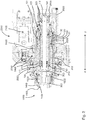
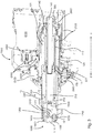
- a preferred example of a drill head 2000 with an extendable cylinder 10 and a multi-functional connector 1000 is shown.
- the multi-functional connector 1000, the extendable cylinder 10 and the drill head 2000 are shown in combination, in particular the multi-functional connector 1000 and the extendable cylinder 10 described herein also can be applied separately.
- Figs. 1 , 3 , and 8 show the drill head 2000 with the extendable cylinder 10 in the extended position
- Figs. 2 , 4 , and 9 show the drill head 2000 with the extendable cylinder 10 in its retracted position
- Figs. 5 - 7 show in particular details of the multi-functional connector 1000
- Figs. 10 - 13 in particular show details of the drill head 2000.
- the drill head 2000 comprises a hydraulic motor 2100 for driving the extendable cylinder 10 connected with it via the spur gear reduction stage 2300.
- the extendable cylinder 10 is supported by taper roller bearings 2400 arranged back to back.
- the hydraulic motor 2100 is able to operate in two different speeds.
- the torque of the hydraulic motor 2100 is transferred to the cylinder 10 via a spur gear reduction stage 2300.
- the two rings of taper roller bearings 2400 are adapted to receive the loads and forces coming from operation of the drill head 2000.
- the drill head 2000, in particular the hydraulic motor 2100 is adapted to provide a rotation of the extendable cylinder 10 of up to 700 rpm and to apply a torque in the first and/or second direction of up to 400 Nm and a flow of hydraulic oil of up to 40 I/min.
- the extendable cylinder 10 can be extended in a distal direction (d) by the provision of hydraulic fluid, as described below.
- the drill head 2000 comprises an extending union 2200 in the form of a rotating union for providing the hydraulic fluid to the rotating extendable cylinder 10.
- the multi-functional connector 1000 is connected to a distal end of the extendable cylinder 10.
- the extendable cylinder 10 comprises a shaft 100 and a piston 200, which is movable relative to the shaft 100 along a longitudinal axis LX to extend or retract the extendable cylinder 10.
- the shaft has an inner part 110 and an outer part 120 and the piston has an inner part 210 and an outer part 220.
- the shaft 100 with its inner and outer parts 110, 120 and the piston 200 with its inner part 210 and its outer part 220 are substantially cylindrical in shape and arranged coaxially.
- a shaft ring volume 101 is formed between the inner part 110and the outer part 120 of the shaft and a piston ring volume 201 is formed between the inner part 210 and the outer part 220 of the piston 200.
- a proximal end 221 of the outer part 220 of the piston 200 is arranged between the inner and outer part 110, 120 of the shaft 100 and sealed against the outer part 120 of the shaft 100.
- a distal end 111 of the inner part 110 of the shaft 100 is arranged between the inner and outer parts 210, 220 of the piston 200.
- the proximal end 221 of the inner part 210 of the piston 200 is sealed against the inner part 110 of the shaft 100.
- the piston 100 and the shaft 200 are connected by a torsionally rigid coupling 30, which is realized by a spline coupling between the outer part 220 of the piston 200 and the inner part 110 of the shaft 100.
- the splines of the spline coupling 30 extend in a direction parallel to the longitudinal axis LX.
- the spline coupling 30 has a longitudinal extension large enough to provide for a reliable torsionally rigid coupling between the shaft 100 and the piston 200 in the extended as well as in the retracted position, in particular when the hydraulic motor 2100 drives the extendable cylinder 10 in a rotational movement.
- the shaft ring volume 101 and the piston ring volume 201 are in fluid communication with each other via the spline coupling 30.
- the extendable cylinder 10 can be extended, this means brought from a position shown in Figs. 2 or 4 into the position shown in Figs. 1 or 3 .
- the extendable cylinder 10 can be retracted by the provision of hydraulic fluid via hydraulic fluid bores 2500 to the intermediary ring volume 40.
- the intermediary ring volume 40 is preferably formed by a section 222 of the outer part 220 of the piston 200, which has a reduced outer diameter.
- hydraulic fluid is retracted from the intermediary ring volume 40 and vice versa to allow for or facilitate the respective retraction or expansion movement.
- seals 300 in particular high-pressure seals where hydraulic fluid is applied, are arranged throughout the drill head 2000 and the extendable cylinder 10 with a multi-functional connector 1000 where needed.
- the high-pressure seals 300 in particular water seals and/or hydraulic fluid seals, preferably are adapted to withstand a fluid provision of 6 I/min at up to 180 bar.
- the extendable cylinder 10 further comprises a supply channel 140 forming a central cavity 141 for supplying a fluid, for example water, to the piston 200, in particular an inner piston volume 212.
- a fluid like water, can be supplied to the supply channel 140 via a fluid connection 2600.
- the supply channel 140 also has a substantially cylindrical shape and is arranged coaxially with the piston 200 and the shaft 100 and provided with respective seals 300 to create a sealed fluid channel.
- the extendable cylinder 10 comprises a transmission element 130 to transmit lateral forces.
- the transmission element 130 is arranged between the outer part 220 of the piston 200 and the outer part 120 of the shaft 100.
- the force transmission element 130 is a ring-shaped element with an axial extension that exceeds its radial extension by a factor larger than 3. Further, the force transmission element 130 is connected to the outer part 220 of the piston 200 by form fit.
- the rotating union 2200 is in fluid communication with the shaft ring volume 101 and/or the piston ring volume 201 and/or the intermediary ring volume 40 and adapted to provide and/or discharge hydraulic fluid from these volumes.
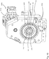
- Fig. 10 shows in particular a ring of taper roller bearings 2400 as well as hydraulic fluid bores 2500 for providing hydraulic fluid to the piston, ring, and/or intermediary ring volume 201, 101, 40 for moving the piston 200.
- the spur gear reduction stage 2300 can be seen in particular in Fig. 11.
- Fig. 11 further shows speed sensors 2700 of the drill head 2000 to control the speed of the rotation.
- Fig. 12 shows in particular the fluid or water connection 2600 to provide fluid, like water, to the central cavity 141 of the supply channel 140.
- Fig. 13 shows in particular the hydraulic fluid bores 2500 providing the motor with hydraulic oil.
- the multi-functional connector 1000 is connected to the outer part 220 of the piston 200 via a threaded connection 1700.
- the multi-functional connector is secured via an engagement element 1400.
- the engagement element 1400 is arranged at an outer periphery of the first connecting element 1100 and adapted to engage the piston 200, in particular the outer part 220 of the piston 200 in a torsion proof way, in particular via a form fit, interlocking fit or positive fit.
- the engagement element 1400 has six evenly spaced recesses in its outer circumference and six corresponding protrusions on the distal end of the outer part 220 of the shaft 200 project into these recesses.
- the engagement element 1400 can be secured by a ring or e-clip 1600.
- the multi-functional connector 1000 comprises a first connecting element 1100, a second connecting element 1300 and a retainer element 1200.
- the first connecting element has a first receptacle 1110 to receive a connecting section of a first functional drill element therein.
- the second connecting element 1300 has a second receptacle 1310 to receive a connecting section of a second functional drill element therein.
- the second connecting element 1300 is arranged proximal (p) to the first connecting element 1100 and the retainer element 1200 is arranged between the first and second connecting elements 1100, 1200.
- the retainer element 1200 has a retainer opening 1210 to receive the connecting section of the second functional drill element therethrough.
- the first receptacle 1110 has a hexagonal cross-sectional shape and is particularly suitable to engage an anchor nut or tensioning rod.
- the first receptacle 1110 has six driving surfaces 1111 for transferring a torque in a first direction to at least two corresponding contact surfaces on the connecting section of the first functional drill element.
- the second connecting element 1300 further has a fluid provision section 1500 with a cylindrical fluid channel for providing fluid from a proximal end of the multi-functional connector 1000 to the first and second connecting elements 1100, 1300 and the retainer element 1200.
- the second receptacle 1310 is particularly suitable to engage a second functional drill element in the form of a drill steel with a connecting section having a square cross section.
- the second receptacle 1310 has four first driving surfaces 1311 for transferring a torque in a first direction to at least two corresponding first contact surfaces on the connecting section of the second functional drill element in a drill position of the second functional drill element.
- the second receptacle 1310 further has four second driving surfaces 1312 for transferring a torque in a second, opposite direction to at least two corresponding second contact surfaces on the connecting section of the second functional drill element in a retracting position of the second functional drill element.
- the first and second driving surfaces 1311, 1312 of the second receptacle 1310 are arranged alternating along a periphery of the second receptacle 1310. Between pairs of first and second driving surfaces 1311, 1312 rounded corners 1313 are arranged along the periphery of the second receptacle 1310. As can be seen in Fig. 6 , four rounded corners 1313 are present in the second receptacle 1310 of the embodiment shown in the figures.
- Two adjacent first and second driving surfaces 1311, 1312 are preferably arranged under an angle toward each other or, in other words, the first driving surface 1311 is inclined to an adjacent second driving surface 1312.
- the first and second driving surfaces 1311, 1312 of the second receptacle 1310 are arranged to engage a connecting section of the second functional drill element with a square cross section.
- the retainer element 1200 can be seen in particular in Fig. 7 .
- the retainer element 1200 has at least two retaining sections 1213 to prevent a movement of the connecting section of the second functional drill element in a direction parallel to the longitudinal axis LX relative to the second connecting element 1300 in the retracting position of the second functional drill element.
- the retainer element 1200 has four guiding surfaces 1211, wherein between adjacent guiding surfaces 1211 a rounded corner 1212 is arranged (in total four rounded corners).
- the four guiding surfaces 1211 are arranged to engage a connecting section of the second functional drill element with a square cross section in an orientation according to the drill position, in order to let the connecting section of the second functional drill element pass the retainer opening 1210 in its drill position. In the drill position, the connecting section of the second functional drill element would contact the first driving surfaces 1311 of the second receptacle 1300 and the guiding surfaces 1211 of the retainer element 1200.
- an inner envelope of the cross section at the first receptacle 1110 envelopes the cross section of the second receptacle 1310 as well as the cross section of the retainer opening 1210.
- a method for drilling an anchor hole and for tightening an anchor nut can be improved and facilitated.
- a drill steel as a first functional drill element with a connecting section with a square cross section can be inserted through the first receptacle 1110 and the retainer opening 1210 into the second receptacle 1310 in a drill position.
- the extendable cylinder 10 can then be rotated by the hydraulic motor 2100 in a first direction, which results in a corresponding rotation of the drill steel via the first driving surfaces 1311 to drill the anchor hole.
- the extendable cylinder 10 can be driven by the hydraulic motor 2100 into a second, opposite direction with the drill steel in the retracting position. Then the drill steel can be retracted together with the extendable cylinder 10 and the multi-functional connector 1000 from the anchor hole, while the retaining sections 1213 of the retainer element 1200 of the multi-functional connector 1000 prevent a relative longitudinal movement of the drill steel relative to the multi-functional connector 1000.
- the cylinder 10 is rotated by the hydraulic motor 2100 in the first direction, to bring the drill steel into the drill position and to release it from the retaining sections 1213 of the retainer element 1200.
- a tensioning rod can be connected to the first receptacle 1110 or an anchor nut of an anchor can be engaged by the first receptacle 1110. It can be preferred to extend the piston 200 relative to the shaft 100 before the anchor nut is engaged or before the extendable cylinder 10 is then rotated in the first direction to tighten the anchor nut of the anchor.
- the same drill head 2000 can be used for drilling the anchor hole and for tightening an anchor nut without the use of dollies or other adapters. This increases safety and facilitates handling. It further provides for a higher degree in automation of the process of drilling an anchor hole and tightening an anchor nut.
Landscapes
- Engineering & Computer Science (AREA)
- Mining & Mineral Resources (AREA)
- Geology (AREA)
- Life Sciences & Earth Sciences (AREA)
- General Life Sciences & Earth Sciences (AREA)
- Geochemistry & Mineralogy (AREA)
- Mechanical Engineering (AREA)
- Physics & Mathematics (AREA)
- Environmental & Geological Engineering (AREA)
- Fluid Mechanics (AREA)
- Structural Engineering (AREA)
- Earth Drilling (AREA)
- Electron Beam Exposure (AREA)
- Stackable Containers (AREA)
- Manufacturing Of Electrical Connectors (AREA)
Claims (15)
- Raccord multifonctionnel (1000) destiné à relier une pluralité d'éléments de forage fonctionnels à une tête de forage, en particulier à un cylindre déployable d'une tête de forage (2000), le raccord multifonctionnel comprenant- un premier élément de liaison (1100) avec un premier réceptacle (1110) conçu pour recevoir une section de liaison d'un premier élément de forage fonctionnel en son sein,- un deuxième élément de liaison (1300) agencé de manière proximale par rapport au premier élément de liaison selon une direction d'un axe longitudinal (LX) du raccord multifonctionnel avec un deuxième réceptacle (1310) conçu pour recevoir une section de liaison d'un deuxième élément de forage fonctionnel en son sein,- un élément de retenue (1200) agencé entre les premier et deuxième éléments de liaison avec une ouverture d'élément de retenue (1210) destinée à recevoir la section de liaison du deuxième élément de forage fonctionnel à travers celle-ci,
où- le premier réceptacle (1110) présente au moins deux surfaces d'entraînement (1111) destinées à transmettre un couple selon un premier sens à au moins deux surfaces de contact correspondantes sur la section de liaison du premier élément de forage fonctionnel,- le deuxième réceptacle (1310) présente au moins deux surfaces d'entraînement (1311, 1312) destinées à transmettre un couple selon un premier sens et selon un deuxième sens opposé à au moins deux surfaces de contact correspondantes sur la section de liaison du deuxième élément de forage fonctionnel dans une position de rétractation et/ou de forage du deuxième élément de forage fonctionnel, et- l'élément de retenue (1200) présente au moins une section de retenue (1213) pour empêcher un déplacement de la section de liaison du deuxième élément de forage fonctionnel selon une direction parallèle à l'axe longitudinal par rapport au deuxième élément de liaison (1300) dans la position de rétractation du deuxième élément de forage fonctionnel. - Raccord multifonctionnel (1000) selon la revendication 1, dans lequel- le deuxième réceptacle (1310) présente au moins deux premières surfaces d'entraînement (1311) destinées à transmettre un couple selon un premier sens à au moins deux premières surfaces de contact correspondantes sur la section de liaison du deuxième élément de forage fonctionnel dans une position de forage du deuxième élément de forage fonctionnel, et- le deuxième réceptacle (1310) présente au moins deux deuxièmes surfaces d'entraînement (1312) destinées à transmettre un couple selon un deuxième sens opposé à au moins deux deuxièmes surfaces de contact correspondantes sur la section de liaison du deuxième élément de forage fonctionnel dans une position de rétractation du deuxième élément de forage fonctionnel.
- Raccord multifonctionnel (1000) selon la revendication 2, dans lequel
les premières et deuxièmes surfaces d'entraînement (1311, 1312) sont agencées de manière alternée le long d'une périphérie du deuxième réceptacle (1310). - Raccord multifonctionnel (1000) selon au moins l'une des deux revendications précédentes, dans lequel
entre des paires de premières et deuxièmes surfaces d'entraînement (1311, 1312), des coins arrondis (1313) sont agencés le long de la périphérie du deuxième réceptacle (1310). - Raccord multifonctionnel (1000) selon au moins l'une des revendications précédentes 2 à 4, dans lequel
les premières surfaces d'entraînement et/ou les deuxièmes surfaces d'entraînement (1311, 1312) du deuxième réceptacle (1310) sont agencées pour engager une section de liaison du deuxième élément de forage fonctionnel ayant une section transversale carrée. - Raccord multifonctionnel (1000) selon au moins l'une des revendications précédentes, dans lequel
l'élément de retenue (1200) présente au moins deux sections de retenue (1213) pour empêcher un déplacement de la section de liaison du deuxième élément de forage fonctionnel selon une direction parallèle à l'axe longitudinal (LX) par rapport au deuxième élément de liaison (1300) dans la position de rétractation du deuxième élément de forage fonctionnel. - Raccord multifonctionnel (1000) selon au moins l'une des revendications précédentes, dans lequel
le premier réceptacle (1110) a une section transversale de forme hexagonale. - Raccord multifonctionnel (1000) selon au moins l'une des revendications précédentes, dans lequel
une enveloppe intérieure de la section transversale du premier réceptacle (1110) enveloppe la section transversale du deuxième réceptacle (1310) et/ou l'ouverture d'élément de retenue (1210). - Raccord multifonctionnel (1000) selon au moins l'une des revendications précédentes, dans lequel
l'élément de retenue (1200) présente au moins deux surfaces de guidage (1211). - Raccord multifonctionnel (1000) selon la revendication 9, dans lequel
entre les au moins deux surfaces de guidage (1211), un coin arrondi (1212) est agencé. - Raccord multifonctionnel (1000) selon au moins l'une des deux revendications précédentes, dans lequel
les au moins deux surfaces de guidage (1211) sont agencées pour engager une section de liaison du deuxième élément de forage fonctionnel ayant une section transversale carrée selon une orientation suivant la position de forage. - Raccord multifonctionnel (1000) selon au moins l'une des revendications précédentes, comprenant
un élément d'engagement (1400) agencé au niveau d'une périphérie extérieure du premier élément de liaison (1100) et conçu pour engager un cylindre (10) d'une tête de forage (2000) de manière à résister à une torsion. - Raccord multifonctionnel (1000) selon au moins l'une des revendications précédentes, comprenant
une section d'approvisionnement en fluide (1500) avec un canal de fluide destiné à acheminer un fluide depuis une extrémité proximale du raccord (1000) jusqu'au premier élément de liaison (1100) et/ou jusqu'au deuxième élément de liaison (1300) et/ou jusqu'à l'élément de retenue (1200). - Tête de forage (2000), comprenant- un cylindre déployable (10) avec un arbre (100) et un piston (200), le piston étant mobile par rapport à l'arbre le long d'un axe longitudinal (LX) ;- un entraînement (2100) destiné à entraîner en rotation l'arbre (100) du cylindre déployable (10) ;- un raccord de déploiement (2200) conçu pour déployer et/ou rétracter le cylindre déployable (10) le long de l'axe longitudinal (LX) ;- un raccord multifonctionnel (1000) selon au moins l'une des revendications précédentes au niveau d'une extrémité distale (202) du piston, afin de relier un élément de forage fonctionnel à celui-ci.
- Procédé pour forer un trou d'ancrage et serrer un écrou d'ancrage, comprenant les étapes consistant à- équiper une tête de forage (200) d'un raccord multifonctionnel (1000) selon au moins l'une des revendications précédentes,- fournir un fleuret de forage en tant que premier élément de forage fonctionnel,- insérer le fleuret à travers le premier réceptacle (1110) et l'ouverture d'élément de retenue (1210) jusque dans le deuxième réceptacle (1310) dans la position de forage,- faire tourner un cylindre (10) de la tête de forage (2000) avec le raccord multifonctionnel (1000) dans un premier sens,- faire tourner le cylindre (10) de la tête de forage (2000) avec le raccord multifonctionnel (1000) dans un deuxième sens opposé pour amener le fleuret de forage dans la position de rétractation,- rétracter le cylindre avec le raccord (1000) et le fleuret de forage,- faire tourner le cylindre (10) de la tête de forage (2000) avec le raccord multifonctionnel (1000) dans le premier sens pour amener le fleuret de forage dans la position de forage,- retirer le fleuret de forage du raccord multifonctionnel (1000),- engager l'écrou d'ancrage d'un ancrage avec le premier réceptacle (1100),- faire tourner un cylindre (10) de la tête de forage (2000) avec le raccord multifonctionnel (1000) dans un premier sens.
Priority Applications (1)
| Application Number | Priority Date | Filing Date | Title |
|---|---|---|---|
| PL15715212T PL3277910T3 (pl) | 2015-04-02 | 2015-04-02 | Łącznik wielofunkcyjny, głowica wiertnicza, i sposób |
Applications Claiming Priority (1)
| Application Number | Priority Date | Filing Date | Title |
|---|---|---|---|
| PCT/EP2015/057296 WO2016155832A1 (fr) | 2015-04-02 | 2015-04-02 | Raccord multifonctionnel, tête de forage, et procédé |
Publications (2)
| Publication Number | Publication Date |
|---|---|
| EP3277910A1 EP3277910A1 (fr) | 2018-02-07 |
| EP3277910B1 true EP3277910B1 (fr) | 2019-06-12 |
Family
ID=52823619
Family Applications (1)
| Application Number | Title | Priority Date | Filing Date |
|---|---|---|---|
| EP15715212.5A Active EP3277910B1 (fr) | 2015-04-02 | 2015-04-02 | Raccord multifonctionnel, tête de forage, et procédé |
Country Status (11)
| Country | Link |
|---|---|
| US (1) | US10697250B2 (fr) |
| EP (1) | EP3277910B1 (fr) |
| CN (1) | CN107407135B (fr) |
| AU (1) | AU2015388710B2 (fr) |
| BR (1) | BR112017021091A2 (fr) |
| CA (1) | CA2976533C (fr) |
| ES (1) | ES2738419T3 (fr) |
| PL (1) | PL3277910T3 (fr) |
| RU (1) | RU2677728C1 (fr) |
| WO (1) | WO2016155832A1 (fr) |
| ZA (1) | ZA201705596B (fr) |
Families Citing this family (3)
| Publication number | Priority date | Publication date | Assignee | Title |
|---|---|---|---|---|
| US11090733B2 (en) * | 2017-10-03 | 2021-08-17 | Royal Hydraulics Service and Manufacturing Company, Inc. | Integrated drill chuck |
| CN110056316B (zh) * | 2019-05-23 | 2024-06-14 | 山东金开峰机械科技有限公司 | 一种水井钻机水钻接头 |
| CN116025398B (zh) * | 2023-02-07 | 2025-11-04 | 内蒙古必德工业技术有限公司 | 一种高速强力打钻锚固执行机构 |
Family Cites Families (72)
| Publication number | Priority date | Publication date | Assignee | Title |
|---|---|---|---|---|
| US1871528A (en) * | 1930-01-17 | 1932-08-16 | White S Dental Mfg Co | Flexible shaft and casing assembly |
| GB382678A (en) | 1930-09-24 | 1932-11-03 | British Jeffrey Diamond Ltd | Improvements in or relating to rotary drills for drilling rock, coal and the like |
| US3128674A (en) * | 1962-06-25 | 1964-04-14 | Commercial Shearing | Multiple stage telescopic cylinders |
| US3213642A (en) * | 1963-03-18 | 1965-10-26 | Arnold S Stern | Slip-on coupling with overload ring |
| US3505831A (en) * | 1968-07-05 | 1970-04-14 | Skil Corp | Flexible shaft coupler |
| US3603207A (en) * | 1969-05-26 | 1971-09-07 | Koehring Co | Multiple-cylinder telescopic actuator |
| US3759336A (en) * | 1972-01-21 | 1973-09-18 | D Marcovitz | Interchangeable power operated tools |
| US3973468A (en) * | 1973-11-21 | 1976-08-10 | Russell Jr Wayne B | Multi-stage extendible and contractible shaft with shock absorption |
| US4020651A (en) * | 1975-07-03 | 1977-05-03 | Rexnord Inc. | Telescoping drive line |
| US4280373A (en) * | 1979-11-21 | 1981-07-28 | Philadelphia Gear Corporation | Portable drive unit for valve actuator |
| US4541160A (en) * | 1981-02-23 | 1985-09-17 | Roberts Thomas C | Process of using a flexible shaft motor coupling having interchangeable adaptors |
| JPS57186612A (en) * | 1981-05-13 | 1982-11-17 | Yazaki Corp | Coupling device of flexible cable to meter |
| US4553612A (en) * | 1983-11-09 | 1985-11-19 | Durham Marion E | Earth boring machine |
| US4735119A (en) * | 1987-02-26 | 1988-04-05 | Riley Alfred B | Manually operated gear wrench |
| GB8804250D0 (en) * | 1988-02-24 | 1988-03-23 | Boart Uk Ltd | Rock bolt insertion tool |
| CA1333282C (fr) * | 1989-02-21 | 1994-11-29 | J. Ford Brett | Outil de forage a auto-equilibrage |
| US5016691A (en) * | 1990-06-19 | 1991-05-21 | Lucien Bernier | Apparatus for centering template guide on router |
| US5125148A (en) * | 1990-10-03 | 1992-06-30 | Igor Krasnov | Drill string torque coupling and method for making up and breaking out drill string connections |
| CA2036883C (fr) * | 1991-02-22 | 2003-12-02 | Roger F. Masse | Tete de forage a marteaux integres |
| US5158458A (en) * | 1991-06-25 | 1992-10-27 | Perry William L | System for driving and tightening components in a prosthodontic restoration |
| US5613418A (en) * | 1992-03-25 | 1997-03-25 | Man Gutehoffnungshutte Aktiengesellschaft | Multiple-stage hydraulic cylinder |
| DE19510964A1 (de) * | 1995-03-24 | 1996-09-26 | Hilti Ag | Handgerät zur trockenen materialabtragenden Bearbeitung von spröden und/oder duktil versagenden Bauteilen und Adapter für ein Hammerbohrgerät |
| US5586847A (en) * | 1995-06-06 | 1996-12-24 | Mattern, Jr.; Charles J. | Power tool adapter |
| US5626474A (en) * | 1995-06-28 | 1997-05-06 | Kukla; Thomas S. | Implant torque wrench |
| US6607044B1 (en) * | 1997-10-27 | 2003-08-19 | Halliburton Energy Services, Inc. | Three dimensional steerable system and method for steering bit to drill borehole |
| US6923273B2 (en) * | 1997-10-27 | 2005-08-02 | Halliburton Energy Services, Inc. | Well system |
| US6079716A (en) * | 1997-12-12 | 2000-06-27 | Black & Decker Inc. | Removable chuck |
| US6035515A (en) * | 1998-10-16 | 2000-03-14 | Shopvac Corporation | Motor shaft assembly and method |
| US6212763B1 (en) * | 1999-06-29 | 2001-04-10 | Frederic M. Newman | Torque-turn system for a three-element sucker rod joint |
| US6463824B1 (en) * | 2000-02-29 | 2002-10-15 | S-B Power Tool Company | Right angle attachment for power hand tool |
| US6508475B1 (en) * | 2001-10-31 | 2003-01-21 | Hudson Precision Products Co. | Holding apparatus with improved retention ability and method of holding a tool |
| US6712368B2 (en) * | 2001-11-08 | 2004-03-30 | S-B Power Tool Company | Quick attachment release system for a rotary hand tool |
| US7004668B2 (en) * | 2002-10-16 | 2006-02-28 | Mtd Products Inc | Connector for flex shaft for string trimmer |
| US7354230B2 (en) * | 2003-12-23 | 2008-04-08 | Lynn Bauman | Bit holding apparatus for use with a power tool |
| US7703550B2 (en) * | 2004-02-06 | 2010-04-27 | Smith International, Inc. | Down hole motor with locking mechanism |
| WO2005103450A1 (fr) | 2004-04-21 | 2005-11-03 | Shawn Kevin Sutherland | Dispositif de mise sous tension d'un boulon d'ancrage |
| US7641000B2 (en) * | 2004-05-21 | 2010-01-05 | Vermeer Manufacturing Company | System for directional boring including a drilling head with overrunning clutch and method of boring |
| US7308952B2 (en) * | 2004-06-04 | 2007-12-18 | Strazhgorodskiy Semen Iosiphov | Underbalanced drilling method and apparatus |
| DE602006013863D1 (de) * | 2005-11-04 | 2010-06-02 | Bosch Gmbh Robert | Verfahren und vorrichtung für einen gelenkbohrer |
| US7228764B1 (en) * | 2005-12-31 | 2007-06-12 | Proprietary Technologies, Inc. | Maximum engagement wrench |
| SE534183C2 (sv) | 2006-04-28 | 2011-05-24 | Unex Corp | Motordriven vridmomentsförstärkare |
| US7717795B2 (en) * | 2006-06-30 | 2010-05-18 | S.S. White Technologies Inc. | Low vibration noise flexible shaft |
| WO2008143874A1 (fr) * | 2007-05-16 | 2008-11-27 | Stryker Spine | Manche de tournevis multiplicateur de vitesse |
| JP4977584B2 (ja) * | 2007-11-27 | 2012-07-18 | 日本車輌製造株式会社 | 杭打機 |
| DE502008002947D1 (de) * | 2008-06-13 | 2011-05-05 | Bauer Maschinen Gmbh | Bauarbeitsgerät mit ausfahrbarem Mast und Verfahren zum Betrieb eines solchen Bauarbeitsgerätes |
| US20100132530A1 (en) * | 2008-12-03 | 2010-06-03 | Kun-Chen Chen | Multi-Use Punch |
| CN201333537Y (zh) * | 2009-01-13 | 2009-10-28 | 于庆滋 | 一种自紧钻夹头 |
| US8302708B1 (en) * | 2009-05-12 | 2012-11-06 | Dover Bmcs Acquisition Corporation | Rotational drill wrenches and drilling apparatuses including the same |
| CN201565934U (zh) * | 2009-11-06 | 2010-09-01 | 南京德朔实业有限公司 | 一种电动榔头 |
| US8640787B2 (en) * | 2009-12-30 | 2014-02-04 | Daniel F. Rohrer | Portable post driving apparatus |
| EP2345764B1 (fr) * | 2010-01-14 | 2015-08-05 | ABI Anlagentechnik-Baumaschinen-Industriebedarf Maschinenfabrik und Vertriebsgesellschaft mbH | Jumelles télescopiques |
| US8312936B2 (en) * | 2010-02-04 | 2012-11-20 | Robert Bosch Gmbh | Lockout apparatus for protecting an attachment device mounted on rotary power tools |
| US8381834B2 (en) * | 2010-02-04 | 2013-02-26 | Robert Bosch Gmbh | Drive system for interconnecting attachment devices and handheld rotary power tools |
| US8327551B2 (en) * | 2010-02-04 | 2012-12-11 | Robert Bosch Gmbh | Attachment interface for rotary hand tools |
| US8347987B1 (en) * | 2011-07-07 | 2013-01-08 | Seegmiller Ben L | Apparatus and method for installing ground anchoring systems |
| CN202202820U (zh) * | 2011-09-06 | 2012-04-25 | 焦作煤业集团赵固(新乡)能源有限责任公司 | 多功能钎尾套 |
| AU2013209274A1 (en) * | 2012-01-10 | 2014-08-28 | Quantax Pty Ltd | Improved torque tensioning system for cable bolts |
| AU2013209272A1 (en) * | 2012-01-10 | 2014-08-28 | Quantax Pty Ltd | A combination tool for installing and tensioning a cable bolt |
| AT512378B1 (de) | 2012-01-12 | 2014-02-15 | Johann Sen Strasser | Seitenwand für einen transportbehälter |
| DK3158966T3 (en) | 2012-01-13 | 2018-07-16 | Erskine Products Pty Ltd | dental Wedge |
| US9327946B2 (en) * | 2012-07-16 | 2016-05-03 | Altec Industries, Inc. | Hydraulic side load braking system |
| US9630347B2 (en) * | 2013-03-15 | 2017-04-25 | Gala Industries, Inc. | Cutter hub pin drive mechanism and quick disconnect hub for an underfluid pelletizer |
| DE102013012714A1 (de) * | 2013-08-01 | 2015-02-05 | Deilmann-Haniel Mining Systems Gmbh | Einsteckende für ein Bohr- und Ankersetzgerät |
| WO2015026374A1 (fr) * | 2013-08-23 | 2015-02-26 | Halliburton Energy Services, Inc. | Mécanisme anti-calage du moteur |
| EP2875903A1 (fr) * | 2013-11-26 | 2015-05-27 | HILTI Aktiengesellschaft | Cloueur à poudre |
| GB2523128B (en) * | 2014-02-13 | 2018-12-26 | Auger Torque Europe Ltd | Improvements in or relating to a secondary drive unit |
| US9751176B2 (en) * | 2014-05-30 | 2017-09-05 | Black & Decker Inc. | Power tool accessory attachment system |
| CN104213851B (zh) * | 2014-06-18 | 2016-04-20 | 襄阳畅勘智能机械有限公司 | 旋挖钻机潜孔破岩钻油管回转接头孔底止转装置 |
| US20180073309A1 (en) * | 2015-04-02 | 2018-03-15 | Sandvik Intellectual Property Ab | Extendable cyclinder, drill head and method |
| US10760351B2 (en) * | 2015-04-17 | 2020-09-01 | Halliburton Energy Services, Inc. | Coupling mechanism for driveshaft transmission assembly |
| US9725957B2 (en) * | 2015-12-28 | 2017-08-08 | Roddie, Inc. | Hand-portable directional drill and method of use |
| US10220493B2 (en) * | 2016-09-06 | 2019-03-05 | Ingersoll-Rand Company | Spindle lock mechanism for pneumatic right-angle impact tool |
-
2015
- 2015-04-02 AU AU2015388710A patent/AU2015388710B2/en active Active
- 2015-04-02 CA CA2976533A patent/CA2976533C/fr active Active
- 2015-04-02 BR BR112017021091-6A patent/BR112017021091A2/pt not_active IP Right Cessation
- 2015-04-02 WO PCT/EP2015/057296 patent/WO2016155832A1/fr not_active Ceased
- 2015-04-02 US US15/561,046 patent/US10697250B2/en active Active
- 2015-04-02 EP EP15715212.5A patent/EP3277910B1/fr active Active
- 2015-04-02 PL PL15715212T patent/PL3277910T3/pl unknown
- 2015-04-02 RU RU2017134298A patent/RU2677728C1/ru active
- 2015-04-02 CN CN201580078362.5A patent/CN107407135B/zh active Active
- 2015-04-02 ES ES15715212T patent/ES2738419T3/es active Active
-
2017
- 2017-08-17 ZA ZA2017/05596A patent/ZA201705596B/en unknown
Non-Patent Citations (1)
| Title |
|---|
| None * |
Also Published As
| Publication number | Publication date |
|---|---|
| RU2677728C1 (ru) | 2019-01-21 |
| ZA201705596B (en) | 2021-06-30 |
| CA2976533C (fr) | 2022-04-26 |
| EP3277910A1 (fr) | 2018-02-07 |
| BR112017021091A2 (pt) | 2018-07-03 |
| ES2738419T3 (es) | 2020-01-22 |
| CN107407135B (zh) | 2019-10-01 |
| WO2016155832A1 (fr) | 2016-10-06 |
| CA2976533A1 (fr) | 2016-10-06 |
| AU2015388710B2 (en) | 2020-09-03 |
| AU2015388710A1 (en) | 2017-08-31 |
| US10697250B2 (en) | 2020-06-30 |
| US20180073307A1 (en) | 2018-03-15 |
| CN107407135A8 (zh) | 2018-01-12 |
| CN107407135A (zh) | 2017-11-28 |
| PL3277910T3 (pl) | 2019-11-29 |
Similar Documents
| Publication | Publication Date | Title |
|---|---|---|
| US11708725B2 (en) | Drill string rotation brake | |
| US9637883B2 (en) | Apparatus and methods for the placement of pipe piling | |
| EP3685005B1 (fr) | Dispositif de commande rotatif | |
| EP3277910B1 (fr) | Raccord multifonctionnel, tête de forage, et procédé | |
| CA2917480C (fr) | Systemes et procedes de raccordement d'accessoire destines a etre utilises avec des systemes d'entrainement de pieu helicoidal | |
| US20180073309A1 (en) | Extendable cyclinder, drill head and method | |
| EP2844825B1 (fr) | Dispositif de commande d'expansion pour un corps de garniture, ainsi qu'outil de tubulure, procédé et utilisation pour commander l'expansion du corps de garniture | |
| CA2971397A1 (fr) | Garniture d'etancheite | |
| US8495930B2 (en) | Power tong device | |
| JPH0533345A (ja) | 掘管の連結装置 | |
| EP3362644B1 (fr) | Appareil extensible, tête de perçage et procédé | |
| JPH0679895U (ja) | 掘管の連結装置 |
Legal Events
| Date | Code | Title | Description |
|---|---|---|---|
| STAA | Information on the status of an ep patent application or granted ep patent |
Free format text: STATUS: THE INTERNATIONAL PUBLICATION HAS BEEN MADE |
|
| PUAI | Public reference made under article 153(3) epc to a published international application that has entered the european phase |
Free format text: ORIGINAL CODE: 0009012 |
|
| STAA | Information on the status of an ep patent application or granted ep patent |
Free format text: STATUS: REQUEST FOR EXAMINATION WAS MADE |
|
| 17P | Request for examination filed |
Effective date: 20171102 |
|
| AK | Designated contracting states |
Kind code of ref document: A1 Designated state(s): AL AT BE BG CH CY CZ DE DK EE ES FI FR GB GR HR HU IE IS IT LI LT LU LV MC MK MT NL NO PL PT RO RS SE SI SK SM TR |
|
| AX | Request for extension of the european patent |
Extension state: BA ME |
|
| DAV | Request for validation of the european patent (deleted) | ||
| DAX | Request for extension of the european patent (deleted) | ||
| GRAP | Despatch of communication of intention to grant a patent |
Free format text: ORIGINAL CODE: EPIDOSNIGR1 |
|
| STAA | Information on the status of an ep patent application or granted ep patent |
Free format text: STATUS: GRANT OF PATENT IS INTENDED |
|
| INTG | Intention to grant announced |
Effective date: 20181023 |
|
| GRAS | Grant fee paid |
Free format text: ORIGINAL CODE: EPIDOSNIGR3 |
|
| GRAA | (expected) grant |
Free format text: ORIGINAL CODE: 0009210 |
|
| STAA | Information on the status of an ep patent application or granted ep patent |
Free format text: STATUS: THE PATENT HAS BEEN GRANTED |
|
| AK | Designated contracting states |
Kind code of ref document: B1 Designated state(s): AL AT BE BG CH CY CZ DE DK EE ES FI FR GB GR HR HU IE IS IT LI LT LU LV MC MK MT NL NO PL PT RO RS SE SI SK SM TR |
|
| REG | Reference to a national code |
Ref country code: GB Ref legal event code: FG4D |
|
| REG | Reference to a national code |
Ref country code: CH Ref legal event code: EP |
|
| REG | Reference to a national code |
Ref country code: AT Ref legal event code: REF Ref document number: 1142754 Country of ref document: AT Kind code of ref document: T Effective date: 20190615 |
|
| REG | Reference to a national code |
Ref country code: DE Ref legal event code: R096 Ref document number: 602015031766 Country of ref document: DE |
|
| REG | Reference to a national code |
Ref country code: IE Ref legal event code: FG4D |
|
| REG | Reference to a national code |
Ref country code: NL Ref legal event code: MP Effective date: 20190612 |
|
| REG | Reference to a national code |
Ref country code: LT Ref legal event code: MG4D |
|
| PG25 | Lapsed in a contracting state [announced via postgrant information from national office to epo] |
Ref country code: AL Free format text: LAPSE BECAUSE OF FAILURE TO SUBMIT A TRANSLATION OF THE DESCRIPTION OR TO PAY THE FEE WITHIN THE PRESCRIBED TIME-LIMIT Effective date: 20190612 Ref country code: LT Free format text: LAPSE BECAUSE OF FAILURE TO SUBMIT A TRANSLATION OF THE DESCRIPTION OR TO PAY THE FEE WITHIN THE PRESCRIBED TIME-LIMIT Effective date: 20190612 Ref country code: FI Free format text: LAPSE BECAUSE OF FAILURE TO SUBMIT A TRANSLATION OF THE DESCRIPTION OR TO PAY THE FEE WITHIN THE PRESCRIBED TIME-LIMIT Effective date: 20190612 Ref country code: SE Free format text: LAPSE BECAUSE OF FAILURE TO SUBMIT A TRANSLATION OF THE DESCRIPTION OR TO PAY THE FEE WITHIN THE PRESCRIBED TIME-LIMIT Effective date: 20190612 Ref country code: NO Free format text: LAPSE BECAUSE OF FAILURE TO SUBMIT A TRANSLATION OF THE DESCRIPTION OR TO PAY THE FEE WITHIN THE PRESCRIBED TIME-LIMIT Effective date: 20190912 Ref country code: HR Free format text: LAPSE BECAUSE OF FAILURE TO SUBMIT A TRANSLATION OF THE DESCRIPTION OR TO PAY THE FEE WITHIN THE PRESCRIBED TIME-LIMIT Effective date: 20190612 |
|
| PG25 | Lapsed in a contracting state [announced via postgrant information from national office to epo] |
Ref country code: LV Free format text: LAPSE BECAUSE OF FAILURE TO SUBMIT A TRANSLATION OF THE DESCRIPTION OR TO PAY THE FEE WITHIN THE PRESCRIBED TIME-LIMIT Effective date: 20190612 Ref country code: GR Free format text: LAPSE BECAUSE OF FAILURE TO SUBMIT A TRANSLATION OF THE DESCRIPTION OR TO PAY THE FEE WITHIN THE PRESCRIBED TIME-LIMIT Effective date: 20190913 Ref country code: BG Free format text: LAPSE BECAUSE OF FAILURE TO SUBMIT A TRANSLATION OF THE DESCRIPTION OR TO PAY THE FEE WITHIN THE PRESCRIBED TIME-LIMIT Effective date: 20190912 Ref country code: RS Free format text: LAPSE BECAUSE OF FAILURE TO SUBMIT A TRANSLATION OF THE DESCRIPTION OR TO PAY THE FEE WITHIN THE PRESCRIBED TIME-LIMIT Effective date: 20190612 |
|
| REG | Reference to a national code |
Ref country code: AT Ref legal event code: MK05 Ref document number: 1142754 Country of ref document: AT Kind code of ref document: T Effective date: 20190612 |
|
| REG | Reference to a national code |
Ref country code: ES Ref legal event code: FG2A Ref document number: 2738419 Country of ref document: ES Kind code of ref document: T3 Effective date: 20200122 |
|
| PG25 | Lapsed in a contracting state [announced via postgrant information from national office to epo] |
Ref country code: PT Free format text: LAPSE BECAUSE OF FAILURE TO SUBMIT A TRANSLATION OF THE DESCRIPTION OR TO PAY THE FEE WITHIN THE PRESCRIBED TIME-LIMIT Effective date: 20191014 Ref country code: AT Free format text: LAPSE BECAUSE OF FAILURE TO SUBMIT A TRANSLATION OF THE DESCRIPTION OR TO PAY THE FEE WITHIN THE PRESCRIBED TIME-LIMIT Effective date: 20190612 Ref country code: RO Free format text: LAPSE BECAUSE OF FAILURE TO SUBMIT A TRANSLATION OF THE DESCRIPTION OR TO PAY THE FEE WITHIN THE PRESCRIBED TIME-LIMIT Effective date: 20190612 Ref country code: NL Free format text: LAPSE BECAUSE OF FAILURE TO SUBMIT A TRANSLATION OF THE DESCRIPTION OR TO PAY THE FEE WITHIN THE PRESCRIBED TIME-LIMIT Effective date: 20190612 Ref country code: EE Free format text: LAPSE BECAUSE OF FAILURE TO SUBMIT A TRANSLATION OF THE DESCRIPTION OR TO PAY THE FEE WITHIN THE PRESCRIBED TIME-LIMIT Effective date: 20190612 Ref country code: SK Free format text: LAPSE BECAUSE OF FAILURE TO SUBMIT A TRANSLATION OF THE DESCRIPTION OR TO PAY THE FEE WITHIN THE PRESCRIBED TIME-LIMIT Effective date: 20190612 |
|
| PG25 | Lapsed in a contracting state [announced via postgrant information from national office to epo] |
Ref country code: IT Free format text: LAPSE BECAUSE OF FAILURE TO SUBMIT A TRANSLATION OF THE DESCRIPTION OR TO PAY THE FEE WITHIN THE PRESCRIBED TIME-LIMIT Effective date: 20190612 Ref country code: IS Free format text: LAPSE BECAUSE OF FAILURE TO SUBMIT A TRANSLATION OF THE DESCRIPTION OR TO PAY THE FEE WITHIN THE PRESCRIBED TIME-LIMIT Effective date: 20191012 Ref country code: SM Free format text: LAPSE BECAUSE OF FAILURE TO SUBMIT A TRANSLATION OF THE DESCRIPTION OR TO PAY THE FEE WITHIN THE PRESCRIBED TIME-LIMIT Effective date: 20190612 |
|
| REG | Reference to a national code |
Ref country code: DE Ref legal event code: R097 Ref document number: 602015031766 Country of ref document: DE |
|
| PG25 | Lapsed in a contracting state [announced via postgrant information from national office to epo] |
Ref country code: TR Free format text: LAPSE BECAUSE OF FAILURE TO SUBMIT A TRANSLATION OF THE DESCRIPTION OR TO PAY THE FEE WITHIN THE PRESCRIBED TIME-LIMIT Effective date: 20190612 |
|
| PLBE | No opposition filed within time limit |
Free format text: ORIGINAL CODE: 0009261 |
|
| STAA | Information on the status of an ep patent application or granted ep patent |
Free format text: STATUS: NO OPPOSITION FILED WITHIN TIME LIMIT |
|
| PG25 | Lapsed in a contracting state [announced via postgrant information from national office to epo] |
Ref country code: DK Free format text: LAPSE BECAUSE OF FAILURE TO SUBMIT A TRANSLATION OF THE DESCRIPTION OR TO PAY THE FEE WITHIN THE PRESCRIBED TIME-LIMIT Effective date: 20190612 |
|
| 26N | No opposition filed |
Effective date: 20200313 |
|
| PG25 | Lapsed in a contracting state [announced via postgrant information from national office to epo] |
Ref country code: SI Free format text: LAPSE BECAUSE OF FAILURE TO SUBMIT A TRANSLATION OF THE DESCRIPTION OR TO PAY THE FEE WITHIN THE PRESCRIBED TIME-LIMIT Effective date: 20190612 Ref country code: IS Free format text: LAPSE BECAUSE OF FAILURE TO SUBMIT A TRANSLATION OF THE DESCRIPTION OR TO PAY THE FEE WITHIN THE PRESCRIBED TIME-LIMIT Effective date: 20200224 |
|
| PG2D | Information on lapse in contracting state deleted |
Ref country code: IS |
|
| PG25 | Lapsed in a contracting state [announced via postgrant information from national office to epo] |
Ref country code: MC Free format text: LAPSE BECAUSE OF FAILURE TO SUBMIT A TRANSLATION OF THE DESCRIPTION OR TO PAY THE FEE WITHIN THE PRESCRIBED TIME-LIMIT Effective date: 20190612 |
|
| REG | Reference to a national code |
Ref country code: CH Ref legal event code: PL |
|
| PG25 | Lapsed in a contracting state [announced via postgrant information from national office to epo] |
Ref country code: LU Free format text: LAPSE BECAUSE OF NON-PAYMENT OF DUE FEES Effective date: 20200402 Ref country code: LI Free format text: LAPSE BECAUSE OF NON-PAYMENT OF DUE FEES Effective date: 20200430 Ref country code: CH Free format text: LAPSE BECAUSE OF NON-PAYMENT OF DUE FEES Effective date: 20200430 Ref country code: FR Free format text: LAPSE BECAUSE OF NON-PAYMENT OF DUE FEES Effective date: 20200430 |
|
| REG | Reference to a national code |
Ref country code: BE Ref legal event code: MM Effective date: 20200430 |
|
| PG25 | Lapsed in a contracting state [announced via postgrant information from national office to epo] |
Ref country code: BE Free format text: LAPSE BECAUSE OF NON-PAYMENT OF DUE FEES Effective date: 20200430 |
|
| PG25 | Lapsed in a contracting state [announced via postgrant information from national office to epo] |
Ref country code: IE Free format text: LAPSE BECAUSE OF NON-PAYMENT OF DUE FEES Effective date: 20200402 |
|
| PGFP | Annual fee paid to national office [announced via postgrant information from national office to epo] |
Ref country code: CZ Payment date: 20210323 Year of fee payment: 7 |
|
| PGFP | Annual fee paid to national office [announced via postgrant information from national office to epo] |
Ref country code: GB Payment date: 20210318 Year of fee payment: 7 Ref country code: PL Payment date: 20210315 Year of fee payment: 7 |
|
| PGFP | Annual fee paid to national office [announced via postgrant information from national office to epo] |
Ref country code: DE Payment date: 20210316 Year of fee payment: 7 |
|
| PGFP | Annual fee paid to national office [announced via postgrant information from national office to epo] |
Ref country code: ES Payment date: 20210505 Year of fee payment: 7 |
|
| PG25 | Lapsed in a contracting state [announced via postgrant information from national office to epo] |
Ref country code: MT Free format text: LAPSE BECAUSE OF FAILURE TO SUBMIT A TRANSLATION OF THE DESCRIPTION OR TO PAY THE FEE WITHIN THE PRESCRIBED TIME-LIMIT Effective date: 20190612 Ref country code: CY Free format text: LAPSE BECAUSE OF FAILURE TO SUBMIT A TRANSLATION OF THE DESCRIPTION OR TO PAY THE FEE WITHIN THE PRESCRIBED TIME-LIMIT Effective date: 20190612 |
|
| PG25 | Lapsed in a contracting state [announced via postgrant information from national office to epo] |
Ref country code: MK Free format text: LAPSE BECAUSE OF FAILURE TO SUBMIT A TRANSLATION OF THE DESCRIPTION OR TO PAY THE FEE WITHIN THE PRESCRIBED TIME-LIMIT Effective date: 20190612 |
|
| PG25 | Lapsed in a contracting state [announced via postgrant information from national office to epo] |
Ref country code: CZ Free format text: LAPSE BECAUSE OF NON-PAYMENT OF DUE FEES Effective date: 20220402 |
|
| REG | Reference to a national code |
Ref country code: DE Ref legal event code: R119 Ref document number: 602015031766 Country of ref document: DE |
|
| GBPC | Gb: european patent ceased through non-payment of renewal fee |
Effective date: 20220402 |
|
| PG25 | Lapsed in a contracting state [announced via postgrant information from national office to epo] |
Ref country code: GB Free format text: LAPSE BECAUSE OF NON-PAYMENT OF DUE FEES Effective date: 20220402 Ref country code: DE Free format text: LAPSE BECAUSE OF NON-PAYMENT OF DUE FEES Effective date: 20221103 |
|
| REG | Reference to a national code |
Ref country code: ES Ref legal event code: FD2A Effective date: 20230526 |
|
| PG25 | Lapsed in a contracting state [announced via postgrant information from national office to epo] |
Ref country code: PL Free format text: LAPSE BECAUSE OF NON-PAYMENT OF DUE FEES Effective date: 20220402 |
|
| PG25 | Lapsed in a contracting state [announced via postgrant information from national office to epo] |
Ref country code: ES Free format text: LAPSE BECAUSE OF NON-PAYMENT OF DUE FEES Effective date: 20220403 |