EP3278024B1 - Gas burner with burner cover - Google Patents
Gas burner with burner cover Download PDFInfo
- Publication number
- EP3278024B1 EP3278024B1 EP16708456.5A EP16708456A EP3278024B1 EP 3278024 B1 EP3278024 B1 EP 3278024B1 EP 16708456 A EP16708456 A EP 16708456A EP 3278024 B1 EP3278024 B1 EP 3278024B1
- Authority
- EP
- European Patent Office
- Prior art keywords
- gas
- gas distribution
- burner
- segment
- section
- Prior art date
- Legal status (The legal status is an assumption and is not a legal conclusion. Google has not performed a legal analysis and makes no representation as to the accuracy of the status listed.)
- Active
Links
Images




Classifications
-
- F—MECHANICAL ENGINEERING; LIGHTING; HEATING; WEAPONS; BLASTING
- F24—HEATING; RANGES; VENTILATING
- F24C—DOMESTIC STOVES OR RANGES ; DETAILS OF DOMESTIC STOVES OR RANGES, OF GENERAL APPLICATION
- F24C3/00—Stoves or ranges for gaseous fuels
- F24C3/08—Arrangement or mounting of burners
- F24C3/082—Arrangement or mounting of burners on stoves
-
- F—MECHANICAL ENGINEERING; LIGHTING; HEATING; WEAPONS; BLASTING
- F23—COMBUSTION APPARATUS; COMBUSTION PROCESSES
- F23D—BURNERS
- F23D14/00—Burners for combustion of a gas, e.g. of a gas stored under pressure as a liquid
- F23D14/02—Premix gas burners, i.e. in which gaseous fuel is mixed with combustion air upstream of the combustion zone
- F23D14/04—Premix gas burners, i.e. in which gaseous fuel is mixed with combustion air upstream of the combustion zone induction type, e.g. Bunsen burner
- F23D14/06—Premix gas burners, i.e. in which gaseous fuel is mixed with combustion air upstream of the combustion zone induction type, e.g. Bunsen burner with radial outlets at the burner head
-
- F—MECHANICAL ENGINEERING; LIGHTING; HEATING; WEAPONS; BLASTING
- F23—COMBUSTION APPARATUS; COMBUSTION PROCESSES
- F23D—BURNERS
- F23D14/00—Burners for combustion of a gas, e.g. of a gas stored under pressure as a liquid
- F23D14/02—Premix gas burners, i.e. in which gaseous fuel is mixed with combustion air upstream of the combustion zone
- F23D14/04—Premix gas burners, i.e. in which gaseous fuel is mixed with combustion air upstream of the combustion zone induction type, e.g. Bunsen burner
- F23D14/06—Premix gas burners, i.e. in which gaseous fuel is mixed with combustion air upstream of the combustion zone induction type, e.g. Bunsen burner with radial outlets at the burner head
- F23D14/065—Premix gas burners, i.e. in which gaseous fuel is mixed with combustion air upstream of the combustion zone induction type, e.g. Bunsen burner with radial outlets at the burner head with injector axis inclined to the burner head axis
-
- F—MECHANICAL ENGINEERING; LIGHTING; HEATING; WEAPONS; BLASTING
- F23—COMBUSTION APPARATUS; COMBUSTION PROCESSES
- F23D—BURNERS
- F23D14/00—Burners for combustion of a gas, e.g. of a gas stored under pressure as a liquid
- F23D14/20—Non-premix gas burners, i.e. in which gaseous fuel is mixed with combustion air on arrival at the combustion zone
-
- F—MECHANICAL ENGINEERING; LIGHTING; HEATING; WEAPONS; BLASTING
- F23—COMBUSTION APPARATUS; COMBUSTION PROCESSES
- F23D—BURNERS
- F23D14/00—Burners for combustion of a gas, e.g. of a gas stored under pressure as a liquid
- F23D14/46—Details
- F23D14/48—Nozzles
- F23D14/58—Nozzles characterised by the shape or arrangement of the outlet or outlets from the nozzle, e.g. of annular configuration
-
- F—MECHANICAL ENGINEERING; LIGHTING; HEATING; WEAPONS; BLASTING
- F24—HEATING; RANGES; VENTILATING
- F24C—DOMESTIC STOVES OR RANGES ; DETAILS OF DOMESTIC STOVES OR RANGES, OF GENERAL APPLICATION
- F24C3/00—Stoves or ranges for gaseous fuels
- F24C3/08—Arrangement or mounting of burners
-
- F—MECHANICAL ENGINEERING; LIGHTING; HEATING; WEAPONS; BLASTING
- F23—COMBUSTION APPARATUS; COMBUSTION PROCESSES
- F23D—BURNERS
- F23D2900/00—Special features of, or arrangements for burners using fluid fuels or solid fuels suspended in a carrier gas
- F23D2900/14—Special features of gas burners
- F23D2900/14062—Special features of gas burners for cooking ranges having multiple flame rings
-
- F—MECHANICAL ENGINEERING; LIGHTING; HEATING; WEAPONS; BLASTING
- F23—COMBUSTION APPARATUS; COMBUSTION PROCESSES
- F23D—BURNERS
- F23D2900/00—Special features of, or arrangements for burners using fluid fuels or solid fuels suspended in a carrier gas
- F23D2900/14—Special features of gas burners
- F23D2900/14063—Special features of gas burners for cooking ranges having one flame ring fed by multiple venturis
Definitions
- the present invention relates to a gas burner for a Marshsgarmeld.
- Gas burners for household cooking appliances comprise a burner lower part, which can be fastened to a hob plate and a burner cover which can be placed on the burner lower part. Between the burner base and the burner cover a mixing space is provided, in which fuel gas mixes with primary air.
- the burner cap has radially arranged gas distribution channels, which are adapted to distribute the fuel gas / air mixture evenly.
- the US 5,690,483 A describes a gas burner with a burner lower part, a burner cover and an intermediate piece arranged between the burner base and the burner cover. At the burner lower part and the intermediate piece in each case semicircular gas distribution channels are provided, which form circular gas outlet openings in an assembly of the burner lower part and the intermediate piece.
- the US 6,095,802 A shows a gas burner with a burner base and a burner cap, which is placed on the burner base. At the burner lower part and the burner cover each semi-circular gas distribution channels are provided, which form circular gas outlet openings in an assembly of the burner base and the burner cover.
- the FR 461 634 A describes a gas burner with multiple burner rings, which are arranged one above the other. There are provided T-shaped gas outlet openings.
- an object of the present invention is to provide an improved burner cap for a gas burner.
- the burner cap comprises a disc-shaped base portion and one with the
- the gas distributor section includes first gas distribution channels extending radially from an inner surface of the gas distribution section toward an outer edge of the base section, each first gas distribution channel extending through the gas distribution section and having a T-shaped cross-sectional geometry extending in the direction of the first gas distribution channel Base section is pioneeringly open, wherein a T-shaped gas outlet opening is defined by each first gas distribution channel and an upper edge of the burner lower part, wherein the gas distributor section comprises second gas distribution channels, which extend radially from the inner surface of the gas distributor portion in the direction of the outer edge of the base portion, wherein each second Gas distributor passage extends through the gas distributor portion and has a semicircular cross-sectional geometry, which is pioneering open in the direction of the base portion t, wherein a gas outlet opening is defined by each second gas distribution channel and the upper edge of the burner lower part,
- the T-shaped cross-sectional geometry of the gas distribution channels makes it possible to reduce the height of the burner cap in comparison to known rectangular gas distribution channels. This can make the gas burner flatter.
- a flat construction of the gas burner is particularly advantageous in gas stoves with gas burners arranged on a glass ceramic plate.
- the T-shaped cross-sectional geometry leads to an improved efficiency compared to known burner caps with rectangular gas distribution channels. Due to the T-shaped cross-sectional geometry, the air / fuel gas mixture flows out particularly evenly. This reduces the carbon monoxide and soot emissions.
- the gas distribution channels are preferably inclined and arranged in the direction of the base portion of the burner cover upwards. The thus achievable flame angle improves the efficiency of the gas burner again.
- the base portion is preferably circular.
- the base section and the gas distributor section are formed in one piece of material.
- the T-shaped cross-sectional geometry has a horizontal portion and a vertical portion, wherein the horizontal portion is directionally open in the direction of the base portion.
- the open side of the T-shaped cross-sectional geometry is closed when placing the burner cover on a burner lower part in the transmitted sense by an upper edge of the burner lower part, so that a T-shaped gas outlet opening is defined by each gas distribution channel and the upper edge.
- a mixing space available by the fuel mixes with primary air.
- the gas distributor section serves for the uniform distribution of the fuel gas / air mixture.
- the horizontal section is 1.5 times to 6 times, preferably 2 times to 5 times, more preferably 2.5 times to 4 times as wide as the vertical section.
- the gas distribution channels can be milled into the gas distributor section.
- the gas distribution channels can be introduced into the gas distributor section with the aid of a primary shaping method, such as die casting.
- the vertical section extends 1.5 times to 6 times, preferably 2 times to 5 times, more preferably 2.5 times to 4 times as deeply into the gas distributor section as the horizontal section.
- the first gas distribution channel passes through the gas distributor section over its entire thickness.
- the first gas distributor ducts are distributed uniformly over a circumference of the gas distributor section.
- the first gas distribution channels preferably run obliquely in the direction of the outer edge of the base section, starting from the inner surface of the gas distributor section.
- the inner surface of the gas distributor section is inclined at an angle to the base section.
- the fuel gas / air mixture can flow into the gas distribution channels in a particularly simple manner.
- the inner surface is inclined at an angle of 40 ° to 45 ° relative to the central portion of the base portion.
- the burner cover has an annular groove which runs around the gas distributor section.
- the annular groove may, for example, have a quarter-circle-shaped cross-sectional geometry.
- the vertical portion of the T-shaped gas outlet channels preferably opens into the annular groove. As a result, the outflow velocity of the air / fuel gas mixture is modified.
- the burner cover has positioning elements for positioning the burner cover on a burner lower part of the gas burner, the positioning elements extending out of the gas distributor section in the direction away from the base section.
- the positioning elements extend out of an upper side of the gas distributor section.
- receiving sections for receiving the positioning elements are provided in the burner lower part.
- the positioning elements are wedge-shaped.
- the positioning elements may be frusto-conical.
- an upper side of the gas distributor section is inclined in the direction of the outer edge of the base section.
- the outer portion of the base portion is inclined in the direction of the outer edge.
- the upper side can be arranged parallel to the outer section his.
- the top is inclined at an angle of 10 ° to 15 °.
- the gas distribution channels are preferably positioned parallel to the top.
- the burner cap has second gas distribution channels extending radially from the inner surface of the gas distribution section toward the outer edge of the base section, each second gas distribution channel extending through the gas distribution section and having a semi-circular cross-sectional geometry that is directionally open in the direction of the base section.
- a respective gas outlet opening of the second gas distribution channels is defined by the semicircular cross-sectional geometry and the upper edge of the burner lower part.
- the invention is a Ausströmquerrough the second gas distribution channels smaller than a Ausströmquerrough the first gas distribution channels.
- each second gas distribution channel extends through a web of the gas distributor section provided between two first gas distribution channels.
- adjacent to the web side walls of the two first gas distribution channels are made rounded.
- the second gas distribution channels are distributed uniformly over a circumference of the gas distribution section and positioned in pairs opposite each other.
- second gas distribution channels are provided.
- a second gas distribution channel is arranged adjacent to an ignition element of the gas burner.
- the Marshsgarillon can be for example a gas stove or a gas hob.
- burner cap and / or of the gas burner also include not explicitly mentioned combinations of features or embodiments described above or below with regard to the exemplary embodiments.
- the expert will also add individual aspects as improvements or additions to the respective basic shape of the burner cover and / or the gas burner.
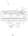
- the Fig. 1 shows a schematic side view of an embodiment of a gas burner 1 for a Marshsgar réelle.
- the Swsgar réelle can, for example, a Gas stove or a gas hob.
- the gas burner 1 comprises a burner lower part 2, which may be attached to a hob plate of the Swsgar réelles.
- the burner base 2 is made for example of an aluminum or magnesium material.
- the burner lower part 2 may be an aluminum die-cast component.
- the gas burner 1 further comprises an ignition element 3 for igniting a fuel gas / air mixture and a thermocouple 4 for flame monitoring.
- thermocouple 4 is connected to a gas shut-off valve of the gas burner 1, that when extinguishing a burner flame of the gas burner 1, the gas shut-off valve interrupts the gas flow to the gas burner 1.
- the ignition element 3 and the thermocouple 4 can be accommodated in receiving sections 5, 6 of the burner base 2.
- the gas burner 1 further comprises a burner cap 7, which is placed on the burner base 2.
- the burner cover 7 can be lifted off the burner lower part 2.
- the burner cover 7 has first gas distribution channels 8, which are provided in a gas distributor section 9 of the burner cover 7.
- the burner cover 7 may be made of an aluminum or ferrous material.
- the gas distributor section 9 rests on an upper edge 10 of the burner lower part 2. Gas outlet openings 11 of the gas burner 1 are defined by the first gas distribution channels 8 and the upper edge 10 of the burner base 2.
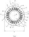
- the Fig. 2 shows an embodiment of a burner cap 7 in a plan view.
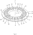
- the Fig. 3 shows the burner cap 7 according to the Fig. 2 in a perspective view.
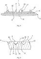
- the Fig. 4 shows the burner cap 7 according to the Fig. 2 in a side view.
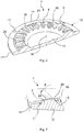
- the Fig. 5 shows an enlarged sectional view of the burner cap 7 according to the Fig. 4
- the Fig. 6 shows a schematic sectional view of the burner cap 7 according to the Fig. 2 and the Fig. 7 shows an enlarged sectional view of the burner cap 7 according to the Fig. 6 ,
- the following is on the Fig. 2 to 7 simultaneously referred to.
- the burner cover 7 has a disk-shaped base portion 12.
- the disc-shaped base portion 12 preferably has a circular geometry.
- Connected to the base section 12 is the annular gas distributor section 9.
- the annular gas distributor section 9 runs around a disk-shaped central section 13 of the base section 12.
- the outer circumference is a annular outer portion 14 of the base portion 12 is provided.
- Blind holes 15 may be provided on the outer section 14. As the Fig. 2 shows four blind holes 15 may be provided, which are arranged in pairs opposite one another.
- the outer portion 14 and the gas distributor portion 9 are arranged concentrically with each other.
- the gas distributor section 9 comprises the first gas distribution channels 8.
- the number of the first gas distribution channels 8 is arbitrary. As the Fig. 2 and 3 For example, twenty-four first gas distribution channels 8 may be provided.
- the first gas distribution channels 8 extend radially from an inner surface 16 (FIG. Fig. 3 In particular, the first gas distribution channels 8 extend in the direction of the outer section 14 of the base section 12.
- the burner cover 7 has a central or symmetrical axis 18. Each first gas distribution channel 8 extends completely through the gas distributor section 9.
- each first gas distribution channel 8 has a T-shaped cross-sectional geometry which is open in the direction away from the base section 12.
- the first gas distribution channel 8 is open in the direction of the upper edge 10 of the burner base 2. That is, the first gas distribution channel 8 is in the transferred sense by the upper edge 10 of the burner base 2 to a T-shaped gas outlet opening 11 (FIG. Fig. 1 ) completed.
- the T-shaped cross-sectional geometry of each first gas distribution channel 8 has a horizontal portion 19 and a vertical portion 20. The horizontal portion 19 is open directionally away from the base portion 12.
- the horizontal portion 19 is 1.5 times to 6 times, preferably 2 times to 5 times, more preferably 2.5 times to 4 times as wide as the vertical portion 20.
- the vertical portion 20 extends preferably 1.5 times to 6 times, more preferably 2 times to 5 times, more preferably 2.5 times to 4 times as deep into the gas distributor section 9 as the horizontal section 19.
- the first gas distribution channels 8 are uniform over a circumference u 9 ( Fig. 2 ) of the gas distributor section 9 distributed.
- the inner surface 16 of the gas distribution section 9 is like the Fig. 7 shows, inclined to the base portion 12 and in particular obliquely inclined to the central portion 13 of the base portion 12.
- the first gas distribution channels 8 are inclined in the direction of the outer edge 17 of the base portion 12.
- the burner cap 7 also has an annular groove on 21 ( Fig. 6, 7 ), which completely orbits around the gas distributor section 9.
- the annular groove 21 is preferably formed in a quarter-circle.
- As the Fig. 6 shows the vertical portions 20 of the first gas distribution channels 8 in the annular groove 21.
- the horizontal portions 19 of the first gas distribution channels 8 are positioned so that they are arranged above the annular groove 21.
- the first gas distribution channels 8 are formed by webs 22 (FIG. Fig. 5 ) separated from each other.
- the burner cover 7 further comprises second gas distribution channels 23 which extend radially from the inner surface 16 of the gas distributor section 9 in the direction of the outer edge 17 of the base portion 12.
- Each second gas distribution channel 23 extends completely through the gas distributor section 9 and has a semicircular cross-sectional geometry open in the direction away from the base section 12.
- a gas outlet opening of the second gas distribution channels 23 is defined by the open semicircular geometry of the second gas distribution channels 23 and the upper edge 10 of the burner base 2.
- Each second gas distribution channel 23 extends through a web 22 of the gas distributor section 9 provided between two first gas distribution channels 8.
- the number of second gas distribution channels 23 is preferably less than the number of first gas distribution channels 8.
- four second gas distribution channels 23 are provided.
- the second gas distribution channels 23 are preferably distributed uniformly over the circumference u 9 of the gas distributor section 9. In particular, two second gas distribution channels 23 are positioned opposite each other.
- a second gas distribution channel 23 with respect to a horizontally disposed first gas distribution channel 8 may be arranged rotated by an angle ⁇ .
- the angle ⁇ can be 22.5 °, for example.
- every second gas distribution channel 23 between two first gas distribution channels 8 is arranged.
- the second gas distribution channel 23 facing side walls 24, 25 of two first gas distribution channel 8 formed rounded.
- each second gas distribution channel 23 is inclined by an angle ⁇ relative to the inner surface 16 of the gas distributor section 9.
- the angle ⁇ can be for example 20 °.
- a depth t of the second gas distribution channel 23 is 0.5 mm, for example.
- the burner cap 7 has, such as the Fig. 6 shows, further positioning elements 27 for positioning the burner cover 7 on the burner lower part 2 of the gas burner 1.
- the positioning elements 27 extend out of the gas distributor section 9 in the direction away from the base section 12.
- An upper side 28 of the gas distributor section 9 is inclined in the direction of the outer edge 17 of the base section 12.
- the gas distribution channels 8, 23 are positioned parallel to the upper side 28 and also extend obliquely from the middle section 13 in the direction of the outer section 14 to the outer section 14.
- the positioning elements 27 are arranged on the inclined top 28, the positioning elements 27 are arranged.
- the positioning elements 27 are in particular wedge-shaped and inclined in the direction of the outer edge 17 of the base portion 12. Due to the wedge-shaped geometry of the positioning elements 27, centering of the burner cover 7 on the burner base 2 can be achieved.
- receiving portions for receiving the positioning elements 27 are provided in the burner lower part 2 .
- the positioning elements 27 are distributed uniformly over the circumference u 9 of the gas distributor section 9 and positioned in pairs opposite one another. As the Fig. 2 and 3 show, the positioning elements 27 are preferably arranged on webs 22 of the gas distributor section 9, which are arranged adjacent to a web 22 with a second gas distribution channel 23.
- the burner cover 7 or the burner base section 12 has an outer diameter d 7 (FIG. Fig. 2 ) on.
- d 7 FIG. Fig. 2
- the first gas distribution channels 8 define the gas volume flow for the normal use of the gas burner 1.
- a particularly stable burner flame is achieved by the T-shaped cross-sectional geometry of the first gas distribution channels 8.
- the T-shaped Geometry of the first gas distribution channels 8 allows a particularly uniform outflow of the air / fuel gas mixture.
- the burner cap 7 can be positioned in a correct position relative to the burner lower part 2.
- a second gas distribution channel 23 can be positioned on an ignition element 3.
- the height of the burner cover 7 and thus the height of the gas burner 1 can be reduced.
- the efficiency of the gas burner 1 is increased.
- the height of the vessel carrier can be reduced, wherein the gas hob can be made with a lower height. Because the gas distribution channels 8, 23 extend obliquely in the direction of the outer edge 17 of the base section 12 starting from the inner surface 16 of the gas distributor section 9, an optimized burner flame angle can be achieved. The partial extinction of the burner flame is prevented to keep carbon monoxide emissions low.
- the Fig. 8 shows a schematic side view of another embodiment of a gas burner 1.
- the Fig. 9 shows a schematic plan view of an embodiment of a burner cap 7 for the gas burner 1 according to the Fig. 8
- the Fig. 10 shows the burner cap 7 in a perspective view.
- the Fig. 11 shows the burner cap 7 in a schematic sectional view. The following is on the 8 to 11 simultaneously referred to.
- the gas burner 1 has a burner lower part 2 and a burner cover 7.
- the gas burner 1 according to the Fig. 8 differs from the gas burner 1 according to the Fig. 1 , in that it has a higher rated power.
- the burner cap 7 has a larger diameter d 7 than the burner cap 7 according to the Fig. 2 .
- the number of first gas distribution channels 8 can be the number of the first Gas distribution channels 8 of the burner cap 7 according to the Fig. 2 correspond.
- Second gas distribution channels 23 are in the Fig. 9 to 11 not shown.
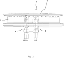
- the Fig. 12 shows a schematic side view of another embodiment of a gas burner 1.
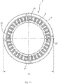
- the Fig. 13 shows a schematic plan view of an embodiment of a burner cap 7 for the gas burner 1 according to the Fig. 12
- the Fig. 14 shows the burner cap 7 in a perspective view.
- the Fig. 15 shows the burner cap 7 in a schematic sectional view. The following is on the Fig. 12 to 15 simultaneously referred to.
- the gas burner 1 according to the Fig. 12 differs from the gas burner 1 according to the Fig. 8 in that it has a higher rated power.
- the gas burner 1 has a burner lower part 2 and a burner cover 7.
- the diameter d 7 of the burner cap 7 according to the Fig. 13 is greater than the diameter d 7 of the burner cap 7 according to the Fig. 9 ,
- the burner cap 7 according to the Fig. 13 has a higher number of first gas distribution channels 8.
- the burner cover 7 differs from the burner cover 7 according to the Fig. 2 in that the positioning elements 27 are not wedge-shaped but frustoconical in shape.
- the relative position of the ignition element 3 relative to a second gas distribution channel 23 is exactly defined.
- the ignition is thereby improved.
- the gas burner 1 can be dimensioned flatter with the same or better efficiency.
- the gas burner 1 can be easily covered with a vessel carrier or Garrost.
- the geometry of the gas distribution channels 8, 23 thus makes it possible to reduce the height of the gas burner 1 with improved efficiency. Characterized in that the gas distribution channels 8, 23 extend obliquely upward in the direction of the outer portion 14 of the base portion 12, an improved burner flame angle can be achieved. This also improves the efficiency of the gas burner 1.
- the diameter d 7 of the burner cap 7 can be increased. The increased diameter d7 improves the flame distribution and the flame stability.
Landscapes
- Engineering & Computer Science (AREA)
- Chemical & Material Sciences (AREA)
- Combustion & Propulsion (AREA)
- Mechanical Engineering (AREA)
- General Engineering & Computer Science (AREA)
- Gas Burners (AREA)
- Baking, Grill, Roasting (AREA)
Description
Die vorliegende Erfindung betrifft einen Gasbrenner für ein Haushaltsgargerät.The present invention relates to a gas burner for a Haushaltsgargerät.
Gasbrenner für Haushaltsgargeräte umfassen ein Brennerunterteil, das an einer Kochfeldplatte befestigt sein kann und einen auf das Brennerunterteil auflegbaren Brennerdeckel. Zwischen dem Brennerunterteil und dem Brennerdeckel ist ein Mischraum vorgesehen, in dem sich Brenngas mit Primärluft mischt. Der Brennerdeckel weist radial angeordnete Gasverteilerkanäle auf, die dazu eingerichtet sind, das Brenngas/LuftGemisch gleichmäßig zu verteilen.Gas burners for household cooking appliances comprise a burner lower part, which can be fastened to a hob plate and a burner cover which can be placed on the burner lower part. Between the burner base and the burner cover a mixing space is provided, in which fuel gas mixes with primary air. The burner cap has radially arranged gas distribution channels, which are adapted to distribute the fuel gas / air mixture evenly.
Die
Die
Vor diesem Hintergrund besteht eine Aufgabe der vorliegenden Erfindung darin, einen verbesserten Brennerdeckel für einen Gasbrenner zur Verfügung zu stellen.Against this background, an object of the present invention is to provide an improved burner cap for a gas burner.
Demgemäß wird ein Gasbrenner für ein Haushaltsgerät mit einem Brennerunterteil und einem auf das Brennerunterteil aufgelegten Brennerdeckel vorgeschlagen. Der Brennerdeckel umfasst einen scheibenförmigen Basisabschnitt und einen mit dem Basisabschnitt verbundenen ringförmigen Gasverteilerabschnitt, wobei der Gasverteilerabschnitt erste Gasverteilerkanäle umfasst, die sich radial von einer Innenfläche des Gasverteilerabschnitts in Richtung einer Außenkante des Basisabschnitts erstrecken, wobei sich jeder erste Gasverteilerkanal durch den Gasverteilerabschnitt hindurcherstreckt und eine T-förmige Querschnittsgeometrie aufweist, die in Richtung von dem Basisabschnitt wegweisend offen ist, wobei durch jeden ersten Gasverteilerkanal und eine Oberkante des Brennerunterteils eine T-förmige Gasaustrittsöffnung definiert ist, wobei der Gasverteilerabschnitt zweite Gasverteilerkanäle umfasst, die sich radial von der Innenfläche des Gasverteilerabschnitts in Richtung der Außenkante des Basisabschnitts erstrecken, wobei sich jeder zweite Gasverteilerkanal durch den Gasverteilerabschnitt hindurcherstreckt und eine halbkreisförmige Querschnittsgeometrie aufweist, die in Richtung von dem Basisabschnitt wegweisend offen ist, wobei durch jeden zweiten Gasverteilerkanal und die Oberkante des Brennerunterteils eine Gasaustrittsöffnung definiert ist, und wobei ein Ausströmquerschnitt der zweiten Gasverteilerkanäle kleiner als ein Ausströmquerschnitt der ersten Gasverteilerkanäle ist.Accordingly, a gas burner for a household appliance with a burner lower part and a burner cap placed on the burner lower part is proposed. The burner cap comprises a disc-shaped base portion and one with the The gas distributor section includes first gas distribution channels extending radially from an inner surface of the gas distribution section toward an outer edge of the base section, each first gas distribution channel extending through the gas distribution section and having a T-shaped cross-sectional geometry extending in the direction of the first gas distribution channel Base section is pioneeringly open, wherein a T-shaped gas outlet opening is defined by each first gas distribution channel and an upper edge of the burner lower part, wherein the gas distributor section comprises second gas distribution channels, which extend radially from the inner surface of the gas distributor portion in the direction of the outer edge of the base portion, wherein each second Gas distributor passage extends through the gas distributor portion and has a semicircular cross-sectional geometry, which is pioneering open in the direction of the base portion t, wherein a gas outlet opening is defined by each second gas distribution channel and the upper edge of the burner lower part, and wherein a Ausströmquerschnitt the second gas distribution channels is smaller than a Ausströmquerschnitt the first gas distribution channels.
Die T-förmige Querschnittsgeometrie der Gasverteilerkanäle ermöglicht es im Vergleich zu bekannten rechteckigen Gasverteilerkanälen, die Bauhöhe des Brennerdeckels zu reduzieren. Hierdurch kann der Gasbrenner flacher gebaut werden. Eine flache Bauweise des Gasbrenners ist insbesondere bei Gasherden mit auf einer Glaskeramikplatte angeordneten Gasbrennern vorteilhaft. Die T-förmige Querschnittsgeometrie führt trotz der reduzierten Bauhöhe des Gasbrenners zu einer verbesserten Effizienz im Vergleich zu bekannten Brennerdeckeln mit rechteckigen Gasverteilerkanälen. Durch die T-förmige Querschnittsgeometrie strömt das Luft/Brenngas-Gemisch besonders gleichmäßig aus. Hierdurch reduzieren sich die Kohlenmonoxid- und Rußemissionen. Die Gasverteilerkanäle sind vorzugsweise schräg verlaufend und in Richtung des Basisabschnitts des Brennerdeckels nach oben angeordnet. Der hierdurch erreichbare Flammenwinkel verbessert die Effizienz des Gasbrenners nochmals. Der Basisabschnitt ist vorzugsweise kreisrund. Insbesondere sind der Basisabschnitt und der Gasverteilerabschnitt materialeinstückig ausgebildet.The T-shaped cross-sectional geometry of the gas distribution channels makes it possible to reduce the height of the burner cap in comparison to known rectangular gas distribution channels. This can make the gas burner flatter. A flat construction of the gas burner is particularly advantageous in gas stoves with gas burners arranged on a glass ceramic plate. In spite of the reduced height of the gas burner, the T-shaped cross-sectional geometry leads to an improved efficiency compared to known burner caps with rectangular gas distribution channels. Due to the T-shaped cross-sectional geometry, the air / fuel gas mixture flows out particularly evenly. This reduces the carbon monoxide and soot emissions. The gas distribution channels are preferably inclined and arranged in the direction of the base portion of the burner cover upwards. The thus achievable flame angle improves the efficiency of the gas burner again. The base portion is preferably circular. In particular, the base section and the gas distributor section are formed in one piece of material.
Gemäß einer Ausführungsform weist die T-förmige Querschnittsgeometrie einen horizontalen Abschnitt und einen vertikalen Abschnitt auf, wobei der horizontale Abschnitt in Richtung von dem Basisabschnitt wegweisend offen ist.According to one embodiment, the T-shaped cross-sectional geometry has a horizontal portion and a vertical portion, wherein the horizontal portion is directionally open in the direction of the base portion.
Die offene Seite der T-förmigen Querschnittsgeometrie wird beim Auflegen des Brennerdeckels auf ein Brennerunterteil im übertragenen Sinne durch eine Oberkante des Brennerunterteils geschlossen, so dass durch jeden Gasverteilerkanal und die Oberkante eine T-förmige Gasaustrittsöffnung definiert ist. Zwischen dem Brennerdeckel und dem Brennerunterteil ist ein Mischraum vorhanden, indem sich das Brenngas mit Primärluft mischt. Der Gasverteilerabschnitt dient dem gleichmäßigen Verteilen des Brenngas/LuftGemisches.The open side of the T-shaped cross-sectional geometry is closed when placing the burner cover on a burner lower part in the transmitted sense by an upper edge of the burner lower part, so that a T-shaped gas outlet opening is defined by each gas distribution channel and the upper edge. Between the burner cover and the burner base is a mixing space available by the fuel mixes with primary air. The gas distributor section serves for the uniform distribution of the fuel gas / air mixture.
Gemäß einer weiteren Ausführungsform ist der horizontale Abschnitt 1,5-mal bis 6-mal, bevorzugt 2-mal bis 5-mal, weiter bevorzugt 2,5-mal bis 4-mal so breit wie der vertikale Abschnitt.According to another embodiment, the horizontal section is 1.5 times to 6 times, preferably 2 times to 5 times, more preferably 2.5 times to 4 times as wide as the vertical section.
Die Gasverteilerkanäle können in den Gasverteilerabschnitt eingefräst sein. Alternativ können die Gasverteilerkanäle mit Hilfe eines urformenden Verfahrens, wie beispielsweise Druckguss, in den Gasverteilerabschnitt eingebracht sein.The gas distribution channels can be milled into the gas distributor section. Alternatively, the gas distribution channels can be introduced into the gas distributor section with the aid of a primary shaping method, such as die casting.
Gemäß einer weiteren Ausführungsform erstreckt sich der vertikale Abschnitt 1,5-mal bis 6-mal, bevorzugt 2-mal bis 5-mal, weiter bevorzugt 2,5-mal bis 4-mal so tief in den Gasverteilerabschnitt hinein wie der horizontale Abschnitt.According to another embodiment, the vertical section extends 1.5 times to 6 times, preferably 2 times to 5 times, more preferably 2.5 times to 4 times as deeply into the gas distributor section as the horizontal section.
Vorzugsweise durchläuft der erste Gasverteilerkanal den Gasverteilerabschnitt über dessen gesamte Dicke.Preferably, the first gas distribution channel passes through the gas distributor section over its entire thickness.
Gemäß einer weiteren Ausführungsform sind die ersten Gasverteilerkanäle gleichmäßig über einen Umfang des Gasverteilerabschnitts verteilt angeordnet.According to a further embodiment, the first gas distributor ducts are distributed uniformly over a circumference of the gas distributor section.
Die ersten Gasverteilerkanäle verlaufen vorzugsweise ausgehend von der Innenfläche des Gasverteilerabschnitts schräg in Richtung der Außenkante des Basisabschnitts.The first gas distribution channels preferably run obliquely in the direction of the outer edge of the base section, starting from the inner surface of the gas distributor section.
Gemäß einer weiteren Ausführungsform ist die Innenfläche des Gasverteilerabschnitts schräg zu dem Basisabschnitt geneigt.According to a further embodiment, the inner surface of the gas distributor section is inclined at an angle to the base section.
Hierdurch kann das Brenngas/Luft-Gemisch besonders einfach in die Gasverteilerkanäle einströmen. Beispielsweise ist die Innenfläche in einem Winkel von 40° bis 45° relativ zu dem Mittelabschnitt des Basisabschnitts geneigt.As a result, the fuel gas / air mixture can flow into the gas distribution channels in a particularly simple manner. For example, the inner surface is inclined at an angle of 40 ° to 45 ° relative to the central portion of the base portion.
Gemäß einer weiteren Ausführungsform weist der Brennerdeckel eine Ringnut auf, die um den Gasverteilerabschnitt umläuft.According to a further embodiment, the burner cover has an annular groove which runs around the gas distributor section.
Die Ringnut kann beispielsweise eine viertelkreisförmige Querschnittsgeometrie aufweisen. Der vertikale Abschnitt der T-förmigen Gasaustrittskanäle mündet vorzugsweise in die Ringnut. Hierdurch wird die Ausströmgeschwindigkeit des Luft/Brenngas-Gemisches modifiziert.The annular groove may, for example, have a quarter-circle-shaped cross-sectional geometry. The vertical portion of the T-shaped gas outlet channels preferably opens into the annular groove. As a result, the outflow velocity of the air / fuel gas mixture is modified.
Gemäß einer Ausführungsform weist der Brennerdeckel Positionierelemente zum Positionieren des Brennerdeckels auf einem Brennerunterteil des Gasbrenners auf, wobei sich die Positionierelemente aus dem Gasverteilerabschnitt heraus in Richtung von dem Basisabschnitt weg erstrecken.According to one embodiment, the burner cover has positioning elements for positioning the burner cover on a burner lower part of the gas burner, the positioning elements extending out of the gas distributor section in the direction away from the base section.
Insbesondere erstrecken sich die Positionierelemente aus einer Oberseite des Gasverteilerabschnitts heraus. Vorzugsweise sind in dem Brennerunterteil Aufnahmeabschnitte zum Aufnehmen der Positionierelemente vorgesehen. Hierdurch ist eine definierte Positionierung des Brennerdeckels auf dem Brennerunterteil möglich.In particular, the positioning elements extend out of an upper side of the gas distributor section. Preferably, receiving sections for receiving the positioning elements are provided in the burner lower part. As a result, a defined positioning of the burner cap on the burner base is possible.
Gemäß einer weiteren Ausführungsform sind die Positionierelemente keilförmig.According to a further embodiment, the positioning elements are wedge-shaped.
Hierdurch kann eine exakte Zentrierung des Brennerdeckels auf dem Brennerunterteil erreicht werden. Alternativ können die Positionierelemente kegelstumpfförmig ausgebildet sein.As a result, an exact centering of the burner cover can be achieved on the burner base. Alternatively, the positioning elements may be frusto-conical.
Gemäß einer weiteren Ausführungsform ist eine Oberseite des Gasverteilerabschnitts in Richtung der Außenkante des Basisabschnitts geneigt.According to a further embodiment, an upper side of the gas distributor section is inclined in the direction of the outer edge of the base section.
Beispielsweise ist auch der Außenabschnitt des Basisabschnitts in Richtung der Außenkante geneigt. Die Oberseite kann parallel zu dem Außenabschnitt angeordnet sein. Beispielsweise ist die Oberseite in einem Winkel von 10° bis 15° geneigt. Die Gasverteilerkanäle sind vorzugsweise parallel zu der Oberseite positioniert.For example, the outer portion of the base portion is inclined in the direction of the outer edge. The upper side can be arranged parallel to the outer section his. For example, the top is inclined at an angle of 10 ° to 15 °. The gas distribution channels are preferably positioned parallel to the top.
Der Brennerdeckel weist zweite Gasverteilerkanäle auf, die sich radial von der Innenfläche des Gasverteilerabschnitts in Richtung der Außenkante des Basisabschnitts erstrecken, wobei sich jeder zweite Gasverteilerkanal durch den Gasverteilerabschnitt hindurch erstreckt und eine halbkreisförmige Querschnittsgeometrie aufweist, die in Richtung von dem Basisabschnitt wegweisend offen ist.The burner cap has second gas distribution channels extending radially from the inner surface of the gas distribution section toward the outer edge of the base section, each second gas distribution channel extending through the gas distribution section and having a semi-circular cross-sectional geometry that is directionally open in the direction of the base section.
Eine jeweilige Gasaustrittsöffnung der zweiten Gasverteilerkanäle wird durch die halbkreisförmige Querschnittsgeometrie und die Oberkante des Brennerunterteils definiert. Erfindungsgemäß
ist ein Ausströmquerschnitt der zweiten Gasverteilerkanäle kleiner als ein Ausströmquerschnitt der ersten Gasverteilerkanäle.A respective gas outlet opening of the second gas distribution channels is defined by the semicircular cross-sectional geometry and the upper edge of the burner lower part. According to the invention
is a Ausströmquerschnitt the second gas distribution channels smaller than a Ausströmquerschnitt the first gas distribution channels.
Gemäß einer weiteren Ausführungsform erstreckt sich jeder zweite Gasverteilerkanal durch einen zwischen zwei ersten Gasverteilerkanälen vorgesehenen Steg des Gasverteilerabschnitts hindurch.According to a further embodiment, each second gas distribution channel extends through a web of the gas distributor section provided between two first gas distribution channels.
Vorzugsweise sind an den Steg angrenzende Seitenwände der zwei ersten Gasverteilerkanäle verrundet ausgeführt.Preferably, adjacent to the web side walls of the two first gas distribution channels are made rounded.
Gemäß einer weiteren Ausführungsform sind die zweiten Gasverteilerkanäle gleichmäßig über einen Umfang des Gasverteilerabschnitts verteilt angeordnet und paarweise einander gegenüberliegend positioniert.According to a further embodiment, the second gas distribution channels are distributed uniformly over a circumference of the gas distribution section and positioned in pairs opposite each other.
Beispielsweise sind vier zweite Gasverteilerkanäle vorgesehen. Insbesondere ist ein zweiter Gasverteilerkanal benachbart zu einem Zündelement des Gasbrenners angeordnet. Hierdurch kann stets eine zuverlässige Zündung erreicht werden.For example, four second gas distribution channels are provided. In particular, a second gas distribution channel is arranged adjacent to an ignition element of the gas burner. As a result, a reliable ignition can always be achieved.
Das Haushaltsgargerät kann beispielsweise ein Gasherd oder eine Gaskochstelle sein.The Haushaltsgargerät can be for example a gas stove or a gas hob.
Weitere mögliche Implementierungen des Brennerdeckels und/oder des Gasbrenners umfassen auch nicht explizit genannte Kombinationen von zuvor oder im Folgenden bezüglich der Ausführungsbeispiele beschriebenen Merkmale oder Ausführungsformen. Dabei wird der Fachmann auch Einzelaspekte als Verbesserungen oder Ergänzungen zu der jeweiligen Grundform des Brennerdeckels und/oder des Gasbrenners hinzufügen.Further possible implementations of the burner cap and / or of the gas burner also include not explicitly mentioned combinations of features or embodiments described above or below with regard to the exemplary embodiments. The expert will also add individual aspects as improvements or additions to the respective basic shape of the burner cover and / or the gas burner.
Weitere vorteilhafte Ausgestaltungen und Aspekte des Brennerdeckels und/oder des Gasbrenners sind Gegenstand der Unteransprüche sowie der im Folgenden beschriebenen Ausführungsbeispiele des Brennerdeckels und/oder des Gasbrenners. Im Weiteren werden der Brennerdeckel und/oder der Gasbrenner anhand von bevorzugten Ausführungsformen unter Bezugnahme auf die beigelegten Figuren näher erläutert.
-
Fig. 1 zeigt eine schematische Seitenansicht einer Ausführungsform eines Gasbrenners; -
Fig. 2 zeigt eine schematische Aufsicht einer Ausführungsform eines Brennerdeckels für den Gasbrenner gemäß derFig. 1 ; -
Fig. 3 zeigt eine schematische perspektivische Ansicht des Brennerdeckels gemäß derFig. 2 ; -
Fig. 4 zeigt eine schematische Seitenansicht des Brennerdeckels gemäß derFig. 2 ; -
Fig. 5 zeigt einen vergrößerten Ausschnitt der schematischen Seitenansicht des Brennerdeckels gemäß derFig. 4 ; -
Fig. 6 zeigt eine schematische perspektivische Schnittansicht des Brennerdeckels gemäß derFig. 2 ; -
Fig. 7 zeigt einen vergrößerten Ausschnitt der schematischen Schnittansicht des Brennerdeckels gemäß derFig. 6 ; -
Fig. 8 zeigt eine schematische Seitenansicht einer weiteren Ausführungsform eines Gasbrenners; -
Fig. 9 zeigt eine schematische Aufsicht einer Ausführungsform eines Brennerdeckels für den Gasbrenner gemäß derFig. 8 ; -
Fig. 10 zeigt eine schematische perspektivische Ansicht des Brennerdeckels gemäß derFig. 9 ; -
Fig. 11 zeigt eine schematische Schnittansicht des Brennerdeckels gemäß derFig. 9 ; -
Fig. 12 zeigt eine schematische Seitenansicht einer weiteren Ausführungsform eines Gasbrenners; -
Fig. 13 zeigt eine schematische Aufsicht einer Ausführungsform eines Brennerdeckels für den Gasbrenner gemäß derFig. 12 ; -
Fig. 14 zeigt eine schematische perspektivische Ansicht des Brennerdeckels gemäß derFig. 12 ; und -
Fig. 15 zeigt eine schematische Schnittansicht des Brennerdeckels gemäß derFig. 12 .
-
Fig. 1 shows a schematic side view of an embodiment of a gas burner; -
Fig. 2 shows a schematic plan view of an embodiment of a burner cap for the gas burner according to theFig. 1 ; -
Fig. 3 shows a schematic perspective view of the burner cap according to theFig. 2 ; -
Fig. 4 shows a schematic side view of the burner cap according to theFig. 2 ; -
Fig. 5 shows an enlarged section of the schematic side view of the burner cap according to theFig. 4 ; -
Fig. 6 shows a schematic perspective sectional view of the burner cap according to theFig. 2 ; -
Fig. 7 shows an enlarged section of the schematic sectional view of the burner cap according to theFig. 6 ; -
Fig. 8 shows a schematic side view of another embodiment of a gas burner; -
Fig. 9 shows a schematic plan view of an embodiment of a burner cap for the gas burner according to theFig. 8 ; -
Fig. 10 shows a schematic perspective view of the burner cap according to theFig. 9 ; -
Fig. 11 shows a schematic sectional view of the burner cap according to theFig. 9 ; -
Fig. 12 shows a schematic side view of another embodiment of a gas burner; -
Fig. 13 shows a schematic plan view of an embodiment of a burner cap for the gas burner according to theFig. 12 ; -
Fig. 14 shows a schematic perspective view of the burner cap according to theFig. 12 ; and -
Fig. 15 shows a schematic sectional view of the burner cap according to theFig. 12 ,
In den Figuren sind gleiche oder funktionsgleiche Elemente mit denselben Bezugszeichen versehen worden, sofern nichts anderes angegeben ist.In the figures, the same or functionally identical elements have been given the same reference numerals, unless stated otherwise.
Die
Der Gasbrenner 1 umfasst weiterhin einen Brennerdeckel 7, der auf das Brennerunterteil 2 aufgelegt ist. Insbesondere ist der Brennerdeckel 7 von dem Brennerunterteil 2 abhebbar. Der Brennerdeckel 7 weist erste Gasverteilerkanäle 8 auf, die in einem Gasverteilerabschnitt 9 des Brennerdeckels 7 vorgesehen sind. Der Brennerdeckel 7 kann aus einem Aluminium- oder Eisenwerkstoff gefertigt sein. Der Gasverteilerabschnitt 9 liegt auf einer Oberkante 10 des Brennerunterteils 2 auf. Gasaustrittsöffnungen 11 des Gasbrenners 1 sind durch die ersten Gasverteilerkanäle 8 und die Oberkante 10 des Brennerunterteils 2 definiert.The gas burner 1 further comprises a
Die
Der Brennerdeckel 7 weist einen scheibenförmigen Basisabschnitt 12 auf. Der scheibenförmige Basisabschnitt 12 weist vorzugsweise eine kreisförmige Geometrie auf. Mit dem Basisabschnitt 12 verbunden ist der ringförmige Gasverteilerabschnitt 9. Der ringförmige Gasverteilerabschnitt 9 läuft um einen scheibenförmigen Mittelabschnitt 13 des Basisabschnitts 12 um. Um den Gasverteilerabschnitt 9 außen umlaufend ist ein ringförmiger Außenabschnitt 14 des Basisabschnitts 12 vorgesehen. An dem Außenabschnitt 14 können Sacklochbohrungen 15 vorgesehen sein. Wie die
Der Gasverteilerabschnitt 9 umfasst die ersten Gasverteilerkanäle 8. Die Anzahl der ersten Gasverteilerkanäle 8 ist beliebig. Wie die
Wie die
Die ersten Gasverteilerkanäle 8 sind gleichmäßig über einen Umfang u9 (
Wie die
Wie die
Wie die
Hierdurch kann das Brenngas/Luft-Gemisch besser in die zweiten Gasverteilerkanäle 23 einströmen. Der Winkel β kann beispielsweise 20° betragen. Eine Tiefe t des zweiten Gasverteilerkanals 23 beträgt beispielsweise 0,5 mm.As a result, the fuel gas / air mixture can flow better into the second
Der Brennerdeckel 7 weist, wie beispielsweise die
Auf der geneigten Oberseite 28 sind die Positionierelemente 27 angeordnet. Die Positionierelemente 27 sind insbesondere keilförmig und in Richtung der Außenkante 17 des Basisabschnitts 12 geneigt. Durch die keilförmige Geometrie der Positionierelemente 27 kann eine Zentrierung des Brennerdeckels 7 an dem Brennerunterteil 2 erreicht werden. In dem Brennerunterteil 2 sind vorzugsweise Aufnahmeabschnitte zum Aufnehmen der Positionierelemente 27 vorgesehen. Die Positionierelemente 27 sind gleichmäßig über den Umfang u9 des Gasverteilerabschnitts 9 verteilt angeordnet und paarweise einander gegenüberliegend positioniert. Wie die
Der Brennerdeckel 7 bzw. der Brennerbasisabschnitt 12 weist einen Außendurchmesser d7 (
Die zweiten Gasverteilerkanäle 23, von denen einer in unmittelbarer Nachbarschaft zu dem Zündelement 3 angeordnet ist, verbessern die Ionisation beim Zünden und ermöglichen eine zuverlässige und schnelle Zündung selbst bei hohen Temperaturen, niedrigem Druck und bei Verschmutzung des Brennerdeckels 7. Durch die kleinere Querschnittsgeometrie der zweiten Gasverteilerkanäle 23 strömt das Gas schneller aus diesen aus.The second
Mit Hilfe der Positionierelemente 27 ist der Brennerdeckel 7 in einer korrekten Position relativ zu dem Brennerunterteil 2 positionierbar. Insbesondere ist hierdurch ein zweiter Gasverteilerkanal 23 an einem Zündelement 3 positionierbar. Durch die Modifikation der Querschnittsgeometrie der Gasverteilerkanäle 8, 23 kann die Höhe des Brennerdeckels 7 und damit die Höhe des Gasbrenners 1 reduziert werden. Gleichzeitig wird die Effizienz des Gasbrenners 1 erhöht. Außerdem kann die Höhe des Gefäßträgers reduziert werden, wobei die Gaskochmulde mit geringerer Höhe ausgeführt werden kann. Dadurch, dass die Gasverteilerkanäle 8, 23 ausgehend von der Innenfläche 16 des Gasverteilerabschnitts 9 schräg in Richtung der Außenkante 17 des Basisabschnitts 12 verlaufen, kann ein optimierter Brennerflammenwinkel erreicht werden. Das teilweise Verlöschen der Brennerflamme wird verhindert, um Kohlenmonoxidemissionen gering zu halten.With the aid of the
Die
Der Gasbrenner 1 weist ein Brennerunterteil 2 und einen Brennerdeckel 7 auf. Der Gasbrenner 1 gemäß der
Die
Der Gasbrenner 1 gemäß der
Durch die Positionierung des Brennerdeckels 7 gegenüber dem Brennerunterteil 2 mit Hilfe der Positionierelemente 27 ist die Relativposition des Zündelements 3 relativ zu einem zweiten Gasverteilerkanal 23 exakt definiert. Die Zündung wird hierdurch verbessert. Aufgrund der neuartigen T-förmigen Geometrie der ersten Gasverteilerkanäle 8 kann die Höhe des Brennerdeckels 7 reduziert werden. Hierdurch kann der Gasbrenner 1 bei gleicher oder besserer Effizienz flacher dimensioniert werden. Insbesondere kann der Gasbrenner 1 einfach mit einem Gefäßträger oder Garrost abgedeckt werden. Die Geometrie der Gasverteilerkanäle 8, 23 erlaubt es somit, die Höhe des Gasbrenners 1 bei verbesserter Effizienz zu reduzieren. Dadurch, dass die Gasverteilerkanäle 8, 23 schräg nach oben in Richtung des Außenabschnitts 14 des Basisabschnitts 12 verlaufen, kann ein verbesserter Brennerflammenwinkel erreicht werden. Dies verbessert ebenfalls die Effizienz des Gasbrenners 1. Neben der Reduktion der Höhe des Gasbrenners 1 kann der Durchmesser d7 des Brennerdeckels 7 vergrößert werden. Durch den vergrößerten Durchmesser d7 verbessern sich die Flammenverteilung und die Flammenstabilität.By positioning the
- 11
- Gasbrennergas burner
- 22
- BrennerunterteilBurner base
- 33
- Zündelementigniter
- 44
- Thermoelementthermocouple
- 55
- Aufnahmeabschnittreceiving portion
- 66
- Aufnahmeabschnittreceiving portion
- 77
- Brennerdeckelburner caps
- 88th
- GasverteilerkanalGas distribution channel
- 99
- GasverteilerabschnittGas distributor section
- 1010
- Oberkantetop edge
- 1111
- GasaustrittsöffnungGas outlet
- 1212
- Basisabschnittbase section
- 1313
- Mittelabschnittmidsection
- 1414
- Außenabschnittouter portion
- 1515
- SacklochbohrungBlind hole
- 1616
- Innenflächepalm
- 1717
- Außenkanteouter edge
- 1818
- Mittelachsecentral axis
- 1919
- Abschnittsection
- 2020
- Abschnittsection
- 2121
- Ringnutring groove
- 2222
- Stegweb
- 2323
- GasverteilerkanalGas distribution channel
- 2424
- SeitenwandSide wall
- 2525
- SeitenwandSide wall
- 2626
- Einströmflächeinflow
- 2727
- Positionierelementpositioning
- 2828
- Oberseitetop
- d7 d 7
- Durchmesserdiameter
- tt
- Tiefedepth
- u9 u 9
- Umfangscope
- αα
- Winkelcorner
- ββ
- Winkelcorner
Claims (13)
- Gas burner (1) for a household cooking appliance, having a lower section (2) of a burner and a burner cover (7) which can be placed onto the lower section (2) of the burner, having a disc-shaped base segment (12) and an annular gas distribution segment (9) connected to the base segment (12), wherein the gas distribution segment (9) comprises first gas distribution channels (8) which extend radially from an inner surface (16) of the gas distribution segment (9) towards an outer edge (17) of the base segment (12), wherein each first gas distribution channel (8) extends through the gas distribution segment (9) and has a T-shaped cross-sectional geometry which is open in the direction pointing away from the base segment (12), wherein the gas distribution segment (9) comprises two gas distribution channels (23) which extend radially from the inner surface (16) of the gas distribution segment (9) towards the outer edge (17) of the base segment (12), wherein each second gas distribution channel (23) extends through the gas distribution segment (9) and has a semi-circular cross-sectional geometry which is open in the direction pointing away from the base segment (12), wherein a gas outlet is defined by each second gas distribution channel (23) and the upper edge (10) of the lower section (2) of the burner, characterised in that a T-shaped gas outlet (11) is defined by each first gas distribution channel (8) and an upper edge (10) of the lower section (2) of the burner, and in that an outflow cross-section of the second gas distribution channels (23) is smaller than an outflow cross-section of the first gas distribution channels (8).
- Gas burner according to claim 1, characterised in that the T-shaped cross-sectional geometry has a horizontal section (19) and a vertical section (20) and in that the horizontal section (19) is open in the direction pointing away from the base segment (12).
- Gas burner according to claim 2, characterised in that the horizontal section (19) is 1.5 to 6 times, preferably 2 to 5 times, more preferably 2.5 to 4 times as wide as the vertical section (20).
- Gas burner according to claim 2 or 3, characterised in that the vertical section (20) extends into the gas distribution segment (9) 1.5 to 6 times, preferably 2 to 5 times, more preferably 2.5 to 4 times as deeply as the horizontal section (19) does.
- Gas burner according to one of claims 1 - 4, characterised in that the first gas distribution channels (8) are arranged so as to be evenly distributed around a periphery (u9) of the gas distribution segment (9).
- Gas burner according to one of claims 1 - 5, characterised in that the inner surface (16) of the gas distribution segment (9) is inclined obliquely to the base segment (12).
- Gas burner according to one of claims 1 - 6, characterised by a circumferential groove (21), which runs around the gas distribution segment (9).
- Gas burner according to one of claims 1 - 7, characterised by positioning elements (27) for positioning the burner cover (7) on a lower section (2) of the gas burner (1) and in that the positioning elements (27) extend out of the gas distribution segment (9) in the direction pointing away from the base segment (12).
- Gas burner according to claim 8, characterised in that the positioning elements (27) are arranged so as to be evenly distributed around a periphery (u9) of the gas distribution segment (9) and are positioned opposite one another in pairs.
- Gas burner according to claim 8 or 9, characterised in that the positioning elements (27) are wedge-shaped.
- Gas burner according to one of claims 1 - 10, characterised in that an upper surface (28) of the gas distribution segment (9) is inclined towards the outer edge (17) of the base segment (12).
- Gas burner according to one of claims 1 - 11, characterised in that each second gas distribution channel (23) extends through a bridge (22) of the gas distribution segment (9), said bridge being provided between two first gas distribution channels (8).
- Gas burner according to one of claims 1 - 12, characterised in that the second gas distribution channels (23) are arranged so as to be evenly distributed around a periphery (u9) of the gas distribution segment (9) and positioned opposite one another in pairs.
Applications Claiming Priority (2)
| Application Number | Priority Date | Filing Date | Title |
|---|---|---|---|
| ES201530437A ES2584921B1 (en) | 2015-03-31 | 2015-03-31 | BURNER COVER AND GAS BURNER |
| PCT/IB2016/051161 WO2016157003A1 (en) | 2015-03-31 | 2016-03-02 | Burner cover and gas burner |
Publications (2)
| Publication Number | Publication Date |
|---|---|
| EP3278024A1 EP3278024A1 (en) | 2018-02-07 |
| EP3278024B1 true EP3278024B1 (en) | 2019-05-08 |
Family
ID=55485027
Family Applications (1)
| Application Number | Title | Priority Date | Filing Date |
|---|---|---|---|
| EP16708456.5A Active EP3278024B1 (en) | 2015-03-31 | 2016-03-02 | Gas burner with burner cover |
Country Status (6)
| Country | Link |
|---|---|
| US (1) | US10415823B2 (en) |
| EP (1) | EP3278024B1 (en) |
| CN (1) | CN107438741B (en) |
| ES (1) | ES2584921B1 (en) |
| TR (1) | TR201907520T4 (en) |
| WO (1) | WO2016157003A1 (en) |
Families Citing this family (7)
| Publication number | Priority date | Publication date | Assignee | Title |
|---|---|---|---|---|
| JP6671233B2 (en) * | 2016-04-28 | 2020-03-25 | リンナイ株式会社 | Stove burner |
| US10551056B2 (en) * | 2017-02-23 | 2020-02-04 | Whirlpool Corporation | Burner base |
| CN108332238B (en) * | 2018-02-08 | 2020-09-08 | 吴联凯 | A Chinese-style gas stove |
| CN108317544B (en) * | 2018-02-08 | 2019-12-31 | 佛山市顺德区吉孚电器有限公司 | Chinese meal type gas cooking stove |
| US11460190B2 (en) * | 2019-07-29 | 2022-10-04 | Haier Us Appliance Solutions, Inc. | Gas burner assembly for a cooktop appliance |
| JP7252619B2 (en) * | 2019-08-27 | 2023-04-05 | 株式会社パロマ | stove burner |
| DE202024102798U1 (en) | 2024-05-29 | 2024-07-18 | AVB UG (haftungsbeschränkt) | Heat distribution plate for an oven with external heat supply |
Family Cites Families (12)
| Publication number | Priority date | Publication date | Assignee | Title |
|---|---|---|---|---|
| FR461634A (en) * | 1913-08-09 | 1914-01-07 | Francois Eugene Nicora | Double crown gas burner |
| DE1950506C3 (en) * | 1969-10-07 | 1981-03-12 | Metallwerke Gebr. Seppelfricke Gmbh & Co, 4650 Gelsenkirchen | Gas burners for gas stoves |
| US6095802A (en) * | 1995-08-31 | 2000-08-01 | Eaton Corporation | Gaseous fuel burner and method of making same |
| US5690483A (en) | 1996-07-17 | 1997-11-25 | Eaton Coporation | Gaseous fuel burner |
| US6371754B1 (en) * | 2000-01-04 | 2002-04-16 | General Electric Company | Flame stabilizing channel for increased turn down of gas burners |
| EP1512908A1 (en) * | 2003-09-05 | 2005-03-09 | Electrolux Home Products Corporation N.V. | Gas burner |
| EP2258982B1 (en) * | 2007-10-23 | 2019-01-16 | Electrolux Home Products Corporation N.V. | Improved gas burner |
| MX345335B (en) * | 2009-12-18 | 2017-01-25 | Mabe S A De C V * | Triple flame section burner. |
| ITAN20120036A1 (en) | 2011-04-19 | 2012-10-20 | Somipress Societa Metalli Iniett Ati S P A | GAS STOVE WITH FLAME TOWARDS THE INSIDE. |
| CN104713087B (en) * | 2015-03-12 | 2017-10-27 | 广东美的厨房电器制造有限公司 | Bottom cup lid and burner and gas appliance |
| EP3270056A4 (en) * | 2015-03-13 | 2018-10-17 | Guangdong Midea Kitchen Appliances | Burner |
| ITUB20153850A1 (en) * | 2015-04-24 | 2017-03-24 | Defendi Italy Srl | GAS BURNER WITH MORE FLAME CHAINS FOR COOKTOPS. |
-
2015
- 2015-03-31 ES ES201530437A patent/ES2584921B1/en not_active Expired - Fee Related
-
2016
- 2016-03-02 TR TR2019/07520T patent/TR201907520T4/en unknown
- 2016-03-02 WO PCT/IB2016/051161 patent/WO2016157003A1/en not_active Ceased
- 2016-03-02 US US15/559,085 patent/US10415823B2/en not_active Expired - Fee Related
- 2016-03-02 EP EP16708456.5A patent/EP3278024B1/en active Active
- 2016-03-02 CN CN201680019858.XA patent/CN107438741B/en active Active
Non-Patent Citations (1)
| Title |
|---|
| None * |
Also Published As
| Publication number | Publication date |
|---|---|
| WO2016157003A1 (en) | 2016-10-06 |
| ES2584921A1 (en) | 2016-09-30 |
| CN107438741B (en) | 2020-07-07 |
| ES2584921B1 (en) | 2017-07-11 |
| CN107438741A (en) | 2017-12-05 |
| EP3278024A1 (en) | 2018-02-07 |
| US10415823B2 (en) | 2019-09-17 |
| TR201907520T4 (en) | 2019-06-21 |
| US20180073731A1 (en) | 2018-03-15 |
Similar Documents
| Publication | Publication Date | Title |
|---|---|---|
| EP3278024B1 (en) | Gas burner with burner cover | |
| EP2211095B1 (en) | Gas burner | |
| EP1028286B1 (en) | Cooking plate for gas ranges | |
| EP2290287B1 (en) | Burner cap for gas range and burner with same | |
| DE69315233T2 (en) | Gas stove burner with three concentric flames | |
| EP1134499B1 (en) | Hob | |
| EP2397757B1 (en) | Burner cap for gas range and burner with same | |
| EP2090826A1 (en) | Gas burner | |
| DE10315343A1 (en) | Gas burner used for cooking, includes burner main body arranged in interior chamber formed by cover and burner ring such that outer diameter of cover is larger than inner diameter of burner ring | |
| EP3679301B1 (en) | Pan support, gas hob and method for producing a pan support | |
| EP2618054A2 (en) | Gas burner with at least three flame circles | |
| DE19931686A1 (en) | Gas burners for cooking points of gas oven has top side of burner lid with vertical annular projection open upwards for peg-shaped projection that projects downwards on grid | |
| EP3255341B1 (en) | Gas burner and household cooking appliance | |
| EP3479022B1 (en) | Gas burner and domestic cooking appliance | |
| EP2439449B1 (en) | Gas burner for a cooking hob | |
| WO2019053542A1 (en) | GAS BURNER, GAS BURNER ASSEMBLY AND HOUSEHOLD GARGERÄT | |
| EP3990832A1 (en) | Pan support, gas hob and method for producing a pan support | |
| EP3198194B1 (en) | Gas burner, gas hob, gas range and method for changing the fuel gas of a gas burner | |
| DE102008019572B4 (en) | Burner crown with discharge holes on different levels and alternately, in one piece, with high performance for burners of commercial kitchens for cooking food | |
| EP2473784B1 (en) | Gas-burner arrangement and gas cooking point | |
| DE10041472C1 (en) | Gas radiant burner | |
| DE3415946C2 (en) | ||
| EP1067334A1 (en) | Gas burner for devices to cook food products | |
| DE708130C (en) | Throttle device for the flue gas duct of kitchen stoves | |
| DE19820445A1 (en) | Gas burner for cooking stove |
Legal Events
| Date | Code | Title | Description |
|---|---|---|---|
| STAA | Information on the status of an ep patent application or granted ep patent |
Free format text: STATUS: THE INTERNATIONAL PUBLICATION HAS BEEN MADE |
|
| PUAI | Public reference made under article 153(3) epc to a published international application that has entered the european phase |
Free format text: ORIGINAL CODE: 0009012 |
|
| STAA | Information on the status of an ep patent application or granted ep patent |
Free format text: STATUS: REQUEST FOR EXAMINATION WAS MADE |
|
| 17P | Request for examination filed |
Effective date: 20171102 |
|
| AK | Designated contracting states |
Kind code of ref document: A1 Designated state(s): AL AT BE BG CH CY CZ DE DK EE ES FI FR GB GR HR HU IE IS IT LI LT LU LV MC MK MT NL NO PL PT RO RS SE SI SK SM TR |
|
| AX | Request for extension of the european patent |
Extension state: BA ME |
|
| DAV | Request for validation of the european patent (deleted) | ||
| DAX | Request for extension of the european patent (deleted) | ||
| GRAP | Despatch of communication of intention to grant a patent |
Free format text: ORIGINAL CODE: EPIDOSNIGR1 |
|
| STAA | Information on the status of an ep patent application or granted ep patent |
Free format text: STATUS: GRANT OF PATENT IS INTENDED |
|
| INTG | Intention to grant announced |
Effective date: 20181109 |
|
| GRAS | Grant fee paid |
Free format text: ORIGINAL CODE: EPIDOSNIGR3 |
|
| GRAA | (expected) grant |
Free format text: ORIGINAL CODE: 0009210 |
|
| STAA | Information on the status of an ep patent application or granted ep patent |
Free format text: STATUS: THE PATENT HAS BEEN GRANTED |
|
| AK | Designated contracting states |
Kind code of ref document: B1 Designated state(s): AL AT BE BG CH CY CZ DE DK EE ES FI FR GB GR HR HU IE IS IT LI LT LU LV MC MK MT NL NO PL PT RO RS SE SI SK SM TR |
|
| REG | Reference to a national code |
Ref country code: GB Ref legal event code: FG4D Free format text: NOT ENGLISH |
|
| REG | Reference to a national code |
Ref country code: CH Ref legal event code: EP Ref country code: AT Ref legal event code: REF Ref document number: 1130724 Country of ref document: AT Kind code of ref document: T Effective date: 20190515 |
|
| REG | Reference to a national code |
Ref country code: DE Ref legal event code: R096 Ref document number: 502016004562 Country of ref document: DE |
|
| REG | Reference to a national code |
Ref country code: IE Ref legal event code: FG4D Free format text: LANGUAGE OF EP DOCUMENT: GERMAN |
|
| REG | Reference to a national code |
Ref country code: NL Ref legal event code: MP Effective date: 20190508 |
|
| REG | Reference to a national code |
Ref country code: LT Ref legal event code: MG4D |
|
| PG25 | Lapsed in a contracting state [announced via postgrant information from national office to epo] |
Ref country code: HR Free format text: LAPSE BECAUSE OF FAILURE TO SUBMIT A TRANSLATION OF THE DESCRIPTION OR TO PAY THE FEE WITHIN THE PRESCRIBED TIME-LIMIT Effective date: 20190508 Ref country code: LT Free format text: LAPSE BECAUSE OF FAILURE TO SUBMIT A TRANSLATION OF THE DESCRIPTION OR TO PAY THE FEE WITHIN THE PRESCRIBED TIME-LIMIT Effective date: 20190508 Ref country code: NO Free format text: LAPSE BECAUSE OF FAILURE TO SUBMIT A TRANSLATION OF THE DESCRIPTION OR TO PAY THE FEE WITHIN THE PRESCRIBED TIME-LIMIT Effective date: 20190808 Ref country code: NL Free format text: LAPSE BECAUSE OF FAILURE TO SUBMIT A TRANSLATION OF THE DESCRIPTION OR TO PAY THE FEE WITHIN THE PRESCRIBED TIME-LIMIT Effective date: 20190508 Ref country code: SE Free format text: LAPSE BECAUSE OF FAILURE TO SUBMIT A TRANSLATION OF THE DESCRIPTION OR TO PAY THE FEE WITHIN THE PRESCRIBED TIME-LIMIT Effective date: 20190508 Ref country code: FI Free format text: LAPSE BECAUSE OF FAILURE TO SUBMIT A TRANSLATION OF THE DESCRIPTION OR TO PAY THE FEE WITHIN THE PRESCRIBED TIME-LIMIT Effective date: 20190508 Ref country code: PT Free format text: LAPSE BECAUSE OF FAILURE TO SUBMIT A TRANSLATION OF THE DESCRIPTION OR TO PAY THE FEE WITHIN THE PRESCRIBED TIME-LIMIT Effective date: 20190908 Ref country code: AL Free format text: LAPSE BECAUSE OF FAILURE TO SUBMIT A TRANSLATION OF THE DESCRIPTION OR TO PAY THE FEE WITHIN THE PRESCRIBED TIME-LIMIT Effective date: 20190508 Ref country code: ES Free format text: LAPSE BECAUSE OF FAILURE TO SUBMIT A TRANSLATION OF THE DESCRIPTION OR TO PAY THE FEE WITHIN THE PRESCRIBED TIME-LIMIT Effective date: 20190508 |
|
| PG25 | Lapsed in a contracting state [announced via postgrant information from national office to epo] |
Ref country code: GR Free format text: LAPSE BECAUSE OF FAILURE TO SUBMIT A TRANSLATION OF THE DESCRIPTION OR TO PAY THE FEE WITHIN THE PRESCRIBED TIME-LIMIT Effective date: 20190809 Ref country code: BG Free format text: LAPSE BECAUSE OF FAILURE TO SUBMIT A TRANSLATION OF THE DESCRIPTION OR TO PAY THE FEE WITHIN THE PRESCRIBED TIME-LIMIT Effective date: 20190808 Ref country code: LV Free format text: LAPSE BECAUSE OF FAILURE TO SUBMIT A TRANSLATION OF THE DESCRIPTION OR TO PAY THE FEE WITHIN THE PRESCRIBED TIME-LIMIT Effective date: 20190508 Ref country code: RS Free format text: LAPSE BECAUSE OF FAILURE TO SUBMIT A TRANSLATION OF THE DESCRIPTION OR TO PAY THE FEE WITHIN THE PRESCRIBED TIME-LIMIT Effective date: 20190508 |
|
| PG25 | Lapsed in a contracting state [announced via postgrant information from national office to epo] |
Ref country code: EE Free format text: LAPSE BECAUSE OF FAILURE TO SUBMIT A TRANSLATION OF THE DESCRIPTION OR TO PAY THE FEE WITHIN THE PRESCRIBED TIME-LIMIT Effective date: 20190508 Ref country code: DK Free format text: LAPSE BECAUSE OF FAILURE TO SUBMIT A TRANSLATION OF THE DESCRIPTION OR TO PAY THE FEE WITHIN THE PRESCRIBED TIME-LIMIT Effective date: 20190508 Ref country code: RO Free format text: LAPSE BECAUSE OF FAILURE TO SUBMIT A TRANSLATION OF THE DESCRIPTION OR TO PAY THE FEE WITHIN THE PRESCRIBED TIME-LIMIT Effective date: 20190508 Ref country code: CZ Free format text: LAPSE BECAUSE OF FAILURE TO SUBMIT A TRANSLATION OF THE DESCRIPTION OR TO PAY THE FEE WITHIN THE PRESCRIBED TIME-LIMIT Effective date: 20190508 Ref country code: SK Free format text: LAPSE BECAUSE OF FAILURE TO SUBMIT A TRANSLATION OF THE DESCRIPTION OR TO PAY THE FEE WITHIN THE PRESCRIBED TIME-LIMIT Effective date: 20190508 |
|
| REG | Reference to a national code |
Ref country code: DE Ref legal event code: R097 Ref document number: 502016004562 Country of ref document: DE |
|
| PG25 | Lapsed in a contracting state [announced via postgrant information from national office to epo] |
Ref country code: SM Free format text: LAPSE BECAUSE OF FAILURE TO SUBMIT A TRANSLATION OF THE DESCRIPTION OR TO PAY THE FEE WITHIN THE PRESCRIBED TIME-LIMIT Effective date: 20190508 |
|
| PLBE | No opposition filed within time limit |
Free format text: ORIGINAL CODE: 0009261 |
|
| STAA | Information on the status of an ep patent application or granted ep patent |
Free format text: STATUS: NO OPPOSITION FILED WITHIN TIME LIMIT |
|
| 26N | No opposition filed |
Effective date: 20200211 |
|
| PG25 | Lapsed in a contracting state [announced via postgrant information from national office to epo] |
Ref country code: PL Free format text: LAPSE BECAUSE OF FAILURE TO SUBMIT A TRANSLATION OF THE DESCRIPTION OR TO PAY THE FEE WITHIN THE PRESCRIBED TIME-LIMIT Effective date: 20190508 |
|
| PG25 | Lapsed in a contracting state [announced via postgrant information from national office to epo] |
Ref country code: SI Free format text: LAPSE BECAUSE OF FAILURE TO SUBMIT A TRANSLATION OF THE DESCRIPTION OR TO PAY THE FEE WITHIN THE PRESCRIBED TIME-LIMIT Effective date: 20190508 |
|
| PG25 | Lapsed in a contracting state [announced via postgrant information from national office to epo] |
Ref country code: MC Free format text: LAPSE BECAUSE OF FAILURE TO SUBMIT A TRANSLATION OF THE DESCRIPTION OR TO PAY THE FEE WITHIN THE PRESCRIBED TIME-LIMIT Effective date: 20190508 |
|
| REG | Reference to a national code |
Ref country code: CH Ref legal event code: PL |
|
| REG | Reference to a national code |
Ref country code: BE Ref legal event code: MM Effective date: 20200331 |
|
| PG25 | Lapsed in a contracting state [announced via postgrant information from national office to epo] |
Ref country code: LU Free format text: LAPSE BECAUSE OF NON-PAYMENT OF DUE FEES Effective date: 20200302 |
|
| PG25 | Lapsed in a contracting state [announced via postgrant information from national office to epo] |
Ref country code: FR Free format text: LAPSE BECAUSE OF NON-PAYMENT OF DUE FEES Effective date: 20200331 Ref country code: IE Free format text: LAPSE BECAUSE OF NON-PAYMENT OF DUE FEES Effective date: 20200302 Ref country code: CH Free format text: LAPSE BECAUSE OF NON-PAYMENT OF DUE FEES Effective date: 20200331 Ref country code: LI Free format text: LAPSE BECAUSE OF NON-PAYMENT OF DUE FEES Effective date: 20200331 |
|
| PG25 | Lapsed in a contracting state [announced via postgrant information from national office to epo] |
Ref country code: BE Free format text: LAPSE BECAUSE OF NON-PAYMENT OF DUE FEES Effective date: 20200331 |
|
| REG | Reference to a national code |
Ref country code: AT Ref legal event code: MM01 Ref document number: 1130724 Country of ref document: AT Kind code of ref document: T Effective date: 20210302 |
|
| PG25 | Lapsed in a contracting state [announced via postgrant information from national office to epo] |
Ref country code: MT Free format text: LAPSE BECAUSE OF FAILURE TO SUBMIT A TRANSLATION OF THE DESCRIPTION OR TO PAY THE FEE WITHIN THE PRESCRIBED TIME-LIMIT Effective date: 20190508 Ref country code: CY Free format text: LAPSE BECAUSE OF FAILURE TO SUBMIT A TRANSLATION OF THE DESCRIPTION OR TO PAY THE FEE WITHIN THE PRESCRIBED TIME-LIMIT Effective date: 20190508 |
|
| PG25 | Lapsed in a contracting state [announced via postgrant information from national office to epo] |
Ref country code: MK Free format text: LAPSE BECAUSE OF FAILURE TO SUBMIT A TRANSLATION OF THE DESCRIPTION OR TO PAY THE FEE WITHIN THE PRESCRIBED TIME-LIMIT Effective date: 20190508 Ref country code: IS Free format text: LAPSE BECAUSE OF FAILURE TO SUBMIT A TRANSLATION OF THE DESCRIPTION OR TO PAY THE FEE WITHIN THE PRESCRIBED TIME-LIMIT Effective date: 20190908 |
|
| PG25 | Lapsed in a contracting state [announced via postgrant information from national office to epo] |
Ref country code: AT Free format text: LAPSE BECAUSE OF NON-PAYMENT OF DUE FEES Effective date: 20210302 |
|
| PGFP | Annual fee paid to national office [announced via postgrant information from national office to epo] |
Ref country code: DE Payment date: 20230331 Year of fee payment: 8 |
|
| P01 | Opt-out of the competence of the unified patent court (upc) registered |
Effective date: 20230504 |
|
| REG | Reference to a national code |
Ref country code: DE Ref legal event code: R119 Ref document number: 502016004562 Country of ref document: DE |
|
| PG25 | Lapsed in a contracting state [announced via postgrant information from national office to epo] |
Ref country code: DE Free format text: LAPSE BECAUSE OF NON-PAYMENT OF DUE FEES Effective date: 20241001 |
|
| PG25 | Lapsed in a contracting state [announced via postgrant information from national office to epo] |
Ref country code: DE Free format text: LAPSE BECAUSE OF NON-PAYMENT OF DUE FEES Effective date: 20241001 |
|
| PGFP | Annual fee paid to national office [announced via postgrant information from national office to epo] |
Ref country code: IT Payment date: 20250331 Year of fee payment: 10 |
|
| PGFP | Annual fee paid to national office [announced via postgrant information from national office to epo] |
Ref country code: GB Payment date: 20260324 Year of fee payment: 11 |
|
| PGFP | Annual fee paid to national office [announced via postgrant information from national office to epo] |
Ref country code: TR Payment date: 20260224 Year of fee payment: 11 |