EP3279096A2 - Dispositif de mise sous vide et procede et appareil de cuisine et dispositif de tiroir dote d'un dispositif de mise sous vide - Google Patents
Dispositif de mise sous vide et procede et appareil de cuisine et dispositif de tiroir dote d'un dispositif de mise sous vide Download PDFInfo
- Publication number
- EP3279096A2 EP3279096A2 EP17187395.3A EP17187395A EP3279096A2 EP 3279096 A2 EP3279096 A2 EP 3279096A2 EP 17187395 A EP17187395 A EP 17187395A EP 3279096 A2 EP3279096 A2 EP 3279096A2
- Authority
- EP
- European Patent Office
- Prior art keywords
- wall
- vacuum
- closed position
- hollow body
- walls
- Prior art date
- Legal status (The legal status is an assumption and is not a legal conclusion. Google has not performed a legal analysis and makes no representation as to the accuracy of the status listed.)
- Granted
Links
Images

Classifications
-
- B—PERFORMING OPERATIONS; TRANSPORTING
- B65—CONVEYING; PACKING; STORING; HANDLING THIN OR FILAMENTARY MATERIAL
- B65B—MACHINES, APPARATUS OR DEVICES FOR, OR METHODS OF, PACKAGING ARTICLES OR MATERIALS; UNPACKING
- B65B31/00—Packaging articles or materials under special atmospheric or gaseous conditions; Adding propellants to aerosol containers
- B65B31/02—Filling, closing, or filling and closing, containers or wrappers in chambers maintained under vacuum or superatmospheric pressure or containing a special atmosphere, e.g. of inert gas
- B65B31/024—Filling, closing, or filling and closing, containers or wrappers in chambers maintained under vacuum or superatmospheric pressure or containing a special atmosphere, e.g. of inert gas specially adapted for wrappers or bags
-
- B—PERFORMING OPERATIONS; TRANSPORTING
- B65—CONVEYING; PACKING; STORING; HANDLING THIN OR FILAMENTARY MATERIAL
- B65B—MACHINES, APPARATUS OR DEVICES FOR, OR METHODS OF, PACKAGING ARTICLES OR MATERIALS; UNPACKING
- B65B59/00—Arrangements to enable machines to handle articles of different sizes, to produce packages of different sizes, to vary the contents of packages, to handle different types of packaging material, or to give access for cleaning or maintenance purposes
- B65B59/001—Arrangements to enable adjustments related to the product to be packaged
-
- A—HUMAN NECESSITIES
- A47—FURNITURE; DOMESTIC ARTICLES OR APPLIANCES; COFFEE MILLS; SPICE MILLS; SUCTION CLEANERS IN GENERAL
- A47B—TABLES; DESKS; OFFICE FURNITURE; CABINETS; DRAWERS; GENERAL DETAILS OF FURNITURE
- A47B2210/00—General construction of drawers, guides and guide devices
- A47B2210/17—Drawers used in connection with household appliances
Definitions
- the present invention relates to a vacuum device, which is particularly suitable for packaging food and a method for operating such a vacuum device and a kitchen appliance with a Vakuumier illusion.
- Vacuum sealers are widely used in the kitchen and in the home. In addition to the vacuuming of food and food for preservation Vakuumierieri also play an important role in the so-called vacuum cooking.
- vacuum cooking the food is cooked gently at low temperatures in a suitable plastic bag. Before cooking, the bag is vacuumed and sealed with the food so that no aromas or liquids are lost during cooking and no oxygen from the air can affect the food.
- Vakuumierakun An essential feature of Vakuumierellan is the size of the vacuum chamber.
- the chamber On the one hand, the chamber has to be large enough to be able to accommodate larger foods, such as B. roast.
- the chamber should not be much larger than the Vakuumiergut, since the evacuation of the chamber otherwise takes a corresponding amount of time. In the prior art, it is therefore customary to reduce the volume of the chamber to be evacuated by inserting plastic parts with a smaller piece of vacuum material in order to save time during evacuation.
- Vakuumierella which are housed in a drawer. Such a placement is particularly convenient because the device does not have to be specially set up on the kitchen worktop, but simply comes into use in the open drawer. It is important that the device on the one hand has a corresponding chamber volume and on the other hand designed as compact as possible to fit into smaller drawers. So have Vakuumierella, which are also suitable for larger roasts, the disadvantage that they need a lot of storage space in a large drawer.
- the vacuuming device is particularly suitable for packaging food and has at least one closable vacuum chamber with at least two walls. At least one evacuation device is provided for evacuating fluid in the vacuum chamber. At least one wall between at least two closed positions is designed to adjust the volume of the Vakuumierhunt adjustable.
- the two walls are each designed as a hollow body open on one side, wherein in the first closed position, the one wall with an outer side of the open hollow body to the other wall and in the second closed position has a wall with an inner side of the open hollow body to the other wall.
- the vacuuming device has many advantages.
- a considerable advantage is that the wall is adjustable.
- the volume of the Vakuumierhunt can be flexibly adapted to the size of the Vakuumierguts.
- the volume may be greater at a second closed position of the wall than at a first closed position.
- vacuum chamber requires little space and thus can be accommodated very compact, z. B. in a drawer with lower height.
- one of the closed positions can be particularly compact, so that this closed position is set for storage.
- a closed position here is in particular a setting of the one and / or the other wall in which the Vakuumierhunt is closed and a Vakuumier ist possible and provided.
- the closed position can be used for vacuuming or for storing the Vakuumier nails. It is also possible that at least one closed position is adjustable for storage, which is not necessarily provided for a Vakuumier religion.
- the evacuation device is preferably suitable and intended to convey a fluid and in particular a gas and more preferably air from the vacuum chamber.
- the evacuation z. B. be designed as a vacuum pump or other suitable compressor device.
- the evacuation device can also be provided separately. In this case, the evacuation z. B. connected via a hose with the vacuum chamber.
- At least one of the walls may at least partially flat and / or curved and / or be formed angular and / or with bulges. Also possible are any other shapes.
- the shape of the wall is designed so that it withstands the expected pressure in vacuum operation well. It can also be provided at least three or four or more walls.
- the two walls can face each other at least in sections. It is preferred that in the second closed position, the distance between the one wall and the other wall is at least partially greater than the distance in the first closed position. Since between at least two of the walls, the vacuum chamber is formed, the volume of which can be adjusted by means of the different distances.
- the preferably two walls forming the vacuum chamber can also each have at least one circumferential edge region and in each case at least one main region enclosed by the edge region.
- the edge region can be designed, for example, as a flange or the like, so that the walls can lie against one another or against one another in this region.
- the distance between the edge region of the one wall and the opposite or adjoining edge region of the other wall in both the first closed position and in the second closed position is less than the distance between the main region of one wall and the opposite main region of the other wall .
- the two walls enclose at least one cavity, which provides the vacuum chamber.
- the vacuum chamber is formed between the main areas.
- an elastic and / or flexible sealing device is arranged on the peripheral edge region of one wall and / or the other wall.
- the sealing device in particular closes off the remaining distance between the peripheral edge region of one wall and the opposite peripheral edge region of the other wall both in the first closed position and in the second closed position.
- the sealing device is preferably suitable and designed to close the Vakuumierhunt gas-tight for the construction of a vacuum.
- the two two walls are each formed as a one-sided open hollow body. Also possible and preferred is that the two walls each have a substantially trough-like contour. Preferably, the walls are arranged in the closed positions to each other so that there is a common cavity, which is provided as Vakuumierhunt.
- the unilaterally open hollow body of a wall may be formed smaller in diameter and / or in depth and / or in height, as the one-sided open hollow body of the other wall.
- the hollow body of a wall is so dimensioned and configured that it is at least partially receivable in the first closed position in the hollow body of the other wall.
- the hollow bodies are designed so that a play or a spacing between the walls remains.
- Such a configuration is particularly advantageous because the volume of the vacuum chamber can be easily adjusted by turning the one wall. If the cavity of one wall protrudes into the cavity of the other wall, a small volume is set. This allows a quick evacuation of the chamber and a space-saving storage even in smaller drawers of a kitchen equipment. If the cavity of one wall, however, away from the cavity of the other wall, a large volume is set, so z. B. also large roast in the chamber are receivable.
- the one wall in the second closed position, has an inner side of the open hollow body to the other wall.
- the inside is in particular the side which lies in the hollow body.
- the cavity of the hollow body of a wall is preferably at least a part of the vacuum chamber in the second closed position.
- one wall in the first closed position, one wall has an outer side of the open hollow body facing the other wall.
- the outside is in particular the side which lies opposite or outside the cavity of the hollow body.
- the outside protrudes at least partially into the hollow body of the other wall.
- the cavity of the hollow body of a wall is preferably no part of the vacuum chamber in the first closed position, so that the volume of the vacuum chamber is smaller than in the second closed position.
- the two aforementioned developments have the advantage that the volume can be adjusted by whether the one wall with the outside or the inside facing the other wall. As a result, for example, by turning the one wall, the volume can be adjusted.
- the one wall has at least one curvature.
- the other wall also has at least one curvature.
- Possible is a square, polygonal or round or semi-circular or partially rounded curvature.
- the curvature lies in the main area and is surrounded by the edge area and / or a flange.
- one wall has a smaller curvature than the other wall, so that the bulges can be placed inside each other.
- the edge regions of the walls are in both closed positions to each other or opposite. This has the advantage that the volume can be adjusted by aligning the bulges.
- the vacuum chamber is very compact when the bulges are in one another.
- At least one wall is formed from the first operating position to the second operating position reversible.
- Possible is z. B. a removable wall, which can be removed by hand, turned and then placed again.
- At least one wall is pivotally received on at least one hinge means about at least one pivot axis.
- the pivoting means in particular a movement in which the one wall can be folded up or down in order to open and / or close the vacuum chamber.
- the one wall can also be turned, wherein the wall can be detached from the hinge device and / or removed.
- the wall can be accommodated by means of plug-in, latching and / or clamping connections on the hinge.
- the one wall on the hinge means is pivotable about at least one pivot axis and rotatably received about at least one axis of rotation. It can be z.
- a hinge may be provided with at least one ball joint. This has the advantage that one wall can be turned without having to separate it from the hinge device. Similar hinge formations are known, for example, from laptops with a rotatable touchscreen, which can be transformed into a tablet computer by turning and swiveling the touchscreen.
- the pivot axis and the axis of rotation lie in different planes.
- the pivot axis and the rotation axis are not arranged parallel to each other. It is also possible that imaginary straight lines cut through the pivot axis and the axis of rotation in one point.
- the pivot axis and the axis of rotation are at an acute or obtuse angle to each other and particularly preferably substantially perpendicular to each other.
- At least one wall is at least partially formed as a lid.
- a lid for the vacuum chamber.
- several interchangeable covers are provided, which are different Have vaults.
- the lid can be replaced without tools, z. B. by disengaging or disengaging from a hinge.
- the vacuuming device can also have at least one welding device.
- the welding device is provided in particular for welding plastics and preferably films and bags.
- the vacuuming device is particularly preferably suitable and designed to be received in a drawer device.
- drawers and drawers which are commonly used in kitchen furniture and catering kitchen equipment.
- a drawer device can also be an extendable shelf in a cabinet or any other fold.
- an embodiment of drawers in a cabinet as it is known, for example, pharmacist cabinets.
- the drawer device can also be unscrewed or swiveled or folded.
- the drawer device may also be designed as a flap in a kitchen furniture, which carries the vacuuming device and sets up by unfolding in the operating position.
- other known storage mechanisms may be included in kitchen equipment, such.
- As the up-foldable cupboards fan tables for bread slicers.
- the vacuum device is intended for use in drawer devices having a height less than 30 cm and preferably less than 20 cm.
- the vacuum is installed in drawers with a height of about 14 cm.
- the vacuuming device can be permanently installed in the drawer device so that the vacuuming device remains there even during operation. It is also possible that the vacuum is stored in the drawer and at least partially removed for operation.
- the inventive method is for operating a Vakuumier beautiful, which is particularly suitable for packaging food.
- the vacuum device has at least one closable vacuum chamber with at least two walls and with an evacuation device for evacuating fluid in the vacuum chamber. At least one wall is adjusted between at least two closed positions to adapt the volume of the vacuum chamber.
- the method according to the invention has many advantages.
- a considerable advantage is that the wall of the vacuum chamber is adjusted between two closed positions.
- the volume of the chamber can be adjusted flexibly and costly to the respective size of the vacuum material.
- Another advantage is that for keeping the Vakuumier worn the closed position can be selected with a smaller chamber volume, so z. B. accommodation in drawers with low height is possible.
- the one wall is at least partially formed as a one-sided open hollow body.
- the one wall is preferably set in a first closed position with an outside of the hollow body toward the other wall.
- the one wall is preferably set in a second closed position with an inner side of the hollow body to the other wall.
- At least one wall is at least partially pivoted about at least one pivot axis in order to adapt the volume of the vacuum chamber.
- at least one wall in particular also at least partially rotated about at least one axis of rotation.
- a hinge device can be provided, which allows pivoting and rotation of the wall by hand.
- a kitchen appliance is to be made available, which has a compact designed and flexible vacuum device for packaging food.
- the kitchen appliance according to the invention is particularly suitable for packaging foodstuffs and comprises at least one vacuuming device according to at least one of the preceding features of the vacuuming device.
- Such a kitchen appliance according to the invention can be used particularly advantageously for vacuuming foods of different sizes, since the volume of the vacuum chamber can be flexibly adapted to the vacuum material.
- the kitchen appliance can also be accommodated to save space, since it takes on very compact dimensions, if the volume of the chamber is adjusted accordingly.
- the vacuuming device has at least one closable vacuum chamber with at least two walls and an evacuation device for evacuating fluid in the vacuum chamber. At least one wall for adjusting the volume of the vacuum chamber between at least two closed positions is adjustable.
- the kitchen appliance is designed as a built-in appliance in a kitchen furniture. Such accommodation is particularly convenient because the appliance does not need to be set up extra on the kitchen counter, but is simply available for use in a kitchen cabinet.
- the kitchen appliance is as Drawer device executed. Such a kitchen appliance is easily accessible and easy to use by simply opening a drawer.
- a kitchen appliance in particular in the form of a drawer device, is to be made available which comprises a vacuum-forming device and has a low overall height.
- the drawer device is particularly suitable for kitchen furniture and comprises at least one Vakuumier Nur, which is intended in particular for the packaging of food.
- the vacuum device has at least one closable vacuum chamber with at least two walls and an evacuation device for evacuating fluid in the vacuum chamber. At least one wall for adjusting the volume of the vacuum chamber between at least two closed positions is adjustable.
- the drawer unit has many advantages.
- a considerable advantage is that the wall of the vacuum chamber can be adjusted between two closed positions.
- the chamber volume can be set for a larger vacuum material.
- the wall can be adjusted so that the vacuum device assumes very compact dimensions and thus the drawer device can be designed with a very low height.
- the drawer device according to the invention thus requires less space than conventional drawers with Vakuumier marn.
- the vacuum device of the kitchen appliance is designed as in at least one of the features described above for the vacuum device.
- the drawer device is preferably designed as described above in the vacuum device.
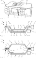
- the FIG. 1 shows kitchen unit 106 designed as kitchen furniture 100 in a schematic, perspective view.
- the kitchen unit 106 here comprises non-visible furniture cassettes, which are clad on their front with furniture fronts and carry a top-mounted worktop 105.
- the kitchen unit 106 here has a cabinet compartment 103 and a plurality of drawer units 7, which are designed as drawers 104 with different heights. Furthermore, a cooking appliance 101 and a hob 102 are integrated into the kitchen unit 106.
- the uppermost of the narrower drawers 104 is designed here as a drawer device 7 according to the invention with an integrated vacuuming device 1.
- a particular advantage of the drawer device 7 is that the vacuum device 1 has an adjustable chamber volume.
- the drawer device 7 according to the invention can be performed with a very low height, such. B. as a drawer 104 with a height of about 14 cm.
- the adjustability of the vacuuming device 1 will be described with reference to FIGS FIGS. 2 to 5 described in more detail.
- the drawer device 7 For vacuuming of food, for example for preservation or preparation for vacuum cooking, the drawer device 7 is opened and the Vakuumier enabled 1 set to the respective size of the Vakuumierguts. Subsequently, the vacuum material is inserted and vacuumed. In order to build up a vacuum in the vacuum chamber 2, an evacuation device 8 is provided, which is designed here as a suitable vacuum pump. After use, the vacuuming device 1 is then adjusted again so that it fits easily into the closed drawer 104.
- the drawer device 7 according to the invention has the advantage that it has a correspondingly low height and at the same time can also be used for larger Vakuumiergut. This saves valuable storage space in the kitchen.
- FIGS. 2 and 3 show a vacuuming device 1 according to the invention, which is designed here as a kitchen appliance 200.
- a vacuuming device 1 can for example also be integrated in a drawer device 7 or designed as such.
- the vacuuming device 1 here comprises a Vakuumierhunt 2, in which the material to be vacuumed is taken.
- the vacuum chamber 2 is from a wall 3 and another Wall 9 enclosed.
- the one wall 3 has a peripheral edge region 13, which rests on a peripheral edge region 19 of the other wall 9.
- a sealing device 12 is provided between the edge regions 13, 19.
- the sealing device 12 is attached to the other wall 9.
- the sealing device 12 can also be provided on the one wall 3 or else on both walls 3, 9.
- the sealing device 12 is formed here as a circumferential ring seal, but are also any other suitable sealing means 12, such. B. labyrinth seals or the like.
- the one wall 3 is formed here as a cover 63, while the other wall 9 forms the associated bottom 69.
- the lid 63 has a main area 23 which is surrounded by the peripheral edge area 13.
- the main area 23 is here provided with a curvature 73, wherein the lid 63 has the shape of a hollow body 33 which is open on one side.
- the bottom 69 also has a main region 29, which is enclosed by the peripheral edge region 19.
- the main portion 29 of the bottom 69 has a bulge 79, so that the bottom 69 is also formed as a one-sided open hollow body 39.
- the bulge 73 of the lid 63 and the bulge 79 of the bottom 69 include a cavity between them, which provides the vacuum chamber 2. In this case, the distance 230 between the main regions 23 and 29 is greater than the distance 130 between the edge regions 13 and 19.
- the distance 130 is sealingly closed by the sealing device 12.
- the sealing device 12 is preferably arranged on the bottom 69. But is also possible an arrangement of the sealing device 12 on both sides of the lid 63, d. H. on the outside 53 and the inside 43.
- the distance 230 between the two main regions 23 and 29 of the cover 63 and the bottom 69 is greater than the distance 130 between their respective edge regions 13 and 19, at least in the second closed position 5, preferably in both closed positions 4, 5 in the first closed position 4 is still a sufficient volume to accommodate appropriate Vakuumiergut can.
- a welding device 10 is installed here.
- the welding device 10 is preferably designed to weld plastic films or plastic bags. As a result, the food in the vacuum chamber 2 after evacuation can be sealed directly in a vacuum-tight plastic bag.
- the lid 63 can be easily swung up.
- the lid 63 is connected to the bottom 69 via a hinge device 6.
- the hinge means 6 a pivoting of the lid 63 about a pivot axis.
- the hinge device 6 also allows the cover 63 to be rotated about an axis of rotation, so that the cover 63 can be turned over between a first closed position 4 and a second closed position 5.
- the first closed position is with respect to the FIG. 2 described in more detail.
- the second closed position 5 is with respect to FIG. 3 described in more detail.
- the hinge device 6 is designed to allow pivoting of the cover 63 about a pivot axis and to permit rotation of the cover 63 about a rotation axis.
- the pivot axis and the axis of rotation are in different levels.
- the rotation of the lid 63 can only be possible from a certain opening angle to avoid unwanted twisting. But is also possible a substantially free rotation and pivoting of the lid 63, z. B. when the hinge device 6 is formed as a ball joint.
- the vacuuming device 1 is shown in a first closed position 4.
- the designed as a hollow body 33 cover 63 is placed so that its outer side 53 to the cavity of the Vakuumierhunt 2 shows. Accordingly, the inside 43 is outside the Vakuumierhunt second
- the height of the vacuum chamber 2 is characterized by at least one or the average distance 14 between the main regions 23 and 29 of the lid 62 and the bottom 69.
- the bulge 73 of the lid 63 is positioned in the bulge 79 of the bottom 69.
- a reduction of the volume of the Vakuumier Anlagen 1 is possible.
- the at least one or the average distance 15 between the main region 23 of the lid 63 and the main region 29 of the bottom 69 is less than the at least one or the average distance 14 in the in FIG. 3 shown second closed position 5, so that the volume of the Vakuumierhunt 2 is set significantly lower here. This has the advantage that smaller Vakuumiergut can be vacuumed quickly and without inserting plastic parts.
- the vacuuming device 1 in a kitchen furniture 100, for example, as a drawer 104 with a height less than 20 cm and preferably in a drawer 104 with a height of 14 cm possible.
- the lid was designed as a correspondingly smaller hollow body 33 or with a smaller curvature 73 in the radius.
- FIG. 3 the vacuuming device 1 is shown in a second closed position 4.
- Vakuumier With Vakuumier Skills 1 a Vakuumier congress both in the first closed position 4 and in the second closed position 5 is possible.
- one of the two closed positions 4, 5 is selected according to the size of the material to be vacuumed.
- the first closed position 4 is suitable for example for small Vakuumier publishede such. Steaks or fish fillets.
- the second closed position 5 is set.
- the lid 63 is simply turned.
- the adaptation of the volume of Vakuumierhunt 2 to the Vakuumiergut has the advantage that the emptying or evacuation of the chamber is much faster.
- the often usual insertion of plastic blocks or the like to reduce the chamber volume is therefore no longer necessary.
- the overall height of the vacuum device 1 can be adjusted.
- the vacuum device 1 provides enough space for larger Vakuumiergut in the second closed position 5, but can also assume a very compact first closed position 4 for storage.
- the Vakuumier dressed 1 has a very low height, so that, for example, a trouble-free accommodation in drawers with a height less than 20 cm and preferably in a drawer with a height of 14 cm is possible.
- FIG. 4 shows a further embodiment of a vacuuming device 1 with a lid 63 with a rounded curvature 73.
- the bottom 69 is formed here as a one-sided open, angular hollow body 39. Shown is a first closed position 4. In this case, the curvature 73 of the lid 63 projects into the cavity of the vacuum chamber 2.
- FIG. 5 shows the vacuum device 1 from the FIG. 4 in a second closed position 5.
- the change between the closed positions 4, 5 is done here by a simple removal, turning and subsequent replacement of the lid 63rd
- the Walls 3, 9 thereby open as unilaterally open hollow body 33, 39 which lie with their edge regions 13, 19 to each other, while their main areas 23, 29 are opposite, so that between them, the cavity for the Vakuumierhunt 2 is formed.
- the hollow body 33, 39 are formed so that they can at least partially interlock in one of the closed positions 4, 5 or are stackable.
- the volume of the vacuum chamber 2 can be adjusted by turning or turning at least one of the walls.
Landscapes
- Engineering & Computer Science (AREA)
- Mechanical Engineering (AREA)
- Chemical & Material Sciences (AREA)
- Dispersion Chemistry (AREA)
- Vacuum Packaging (AREA)
Priority Applications (1)
| Application Number | Priority Date | Filing Date | Title |
|---|---|---|---|
| EP17187395.3A EP3279096B1 (fr) | 2015-09-14 | 2015-09-14 | Dispositif de mise sous vide et procede et appareil de cuisine et dispositif de tiroir dote d'un dispositif de mise sous vide |
Applications Claiming Priority (2)
| Application Number | Priority Date | Filing Date | Title |
|---|---|---|---|
| EP15184985.8A EP3141487B1 (fr) | 2015-09-14 | 2015-09-14 | Dispositif de mise sous vide et procede et appareil de cuisine et dispositif de tiroir dote d'un dispositif de mise sous vide |
| EP17187395.3A EP3279096B1 (fr) | 2015-09-14 | 2015-09-14 | Dispositif de mise sous vide et procede et appareil de cuisine et dispositif de tiroir dote d'un dispositif de mise sous vide |
Related Parent Applications (2)
| Application Number | Title | Priority Date | Filing Date |
|---|---|---|---|
| EP15184985.8A Division EP3141487B1 (fr) | 2015-09-14 | 2015-09-14 | Dispositif de mise sous vide et procede et appareil de cuisine et dispositif de tiroir dote d'un dispositif de mise sous vide |
| EP15184985.8A Division-Into EP3141487B1 (fr) | 2015-09-14 | 2015-09-14 | Dispositif de mise sous vide et procede et appareil de cuisine et dispositif de tiroir dote d'un dispositif de mise sous vide |
Publications (3)
| Publication Number | Publication Date |
|---|---|
| EP3279096A2 true EP3279096A2 (fr) | 2018-02-07 |
| EP3279096A3 EP3279096A3 (fr) | 2018-04-04 |
| EP3279096B1 EP3279096B1 (fr) | 2019-06-12 |
Family
ID=54140345
Family Applications (2)
| Application Number | Title | Priority Date | Filing Date |
|---|---|---|---|
| EP17187395.3A Active EP3279096B1 (fr) | 2015-09-14 | 2015-09-14 | Dispositif de mise sous vide et procede et appareil de cuisine et dispositif de tiroir dote d'un dispositif de mise sous vide |
| EP15184985.8A Active EP3141487B1 (fr) | 2015-09-14 | 2015-09-14 | Dispositif de mise sous vide et procede et appareil de cuisine et dispositif de tiroir dote d'un dispositif de mise sous vide |
Family Applications After (1)
| Application Number | Title | Priority Date | Filing Date |
|---|---|---|---|
| EP15184985.8A Active EP3141487B1 (fr) | 2015-09-14 | 2015-09-14 | Dispositif de mise sous vide et procede et appareil de cuisine et dispositif de tiroir dote d'un dispositif de mise sous vide |
Country Status (2)
| Country | Link |
|---|---|
| EP (2) | EP3279096B1 (fr) |
| DE (1) | DE102016116217A1 (fr) |
Families Citing this family (1)
| Publication number | Priority date | Publication date | Assignee | Title |
|---|---|---|---|---|
| EP3380405B2 (fr) | 2015-11-27 | 2023-03-15 | GEA Food Solutions Germany GmbH | Réduction du volume de chambre lors de l'adaptation de la profondeur d'emboutissage dans la station de scellement au moyen d'une garniture d'étanchéité gonflable |
Family Cites Families (9)
| Publication number | Priority date | Publication date | Assignee | Title |
|---|---|---|---|---|
| FR1212492A (fr) * | 1958-10-17 | 1960-03-24 | Soplaril Sa | Perfectionnements aux machines à souder sous vide les emballages en matière plastique |
| DE3300900A1 (de) * | 1982-01-22 | 1983-08-04 | Supervac Vertriebsgesellschaft mbH Kieteubl & Assler oHG, 1020 Wien | Vorrichtung zum evakuieren und verschliessen von waren, insbesondere von lebensmittel enthaltenden, angenaehert gasdichten beuteln, huellen od. dgl. |
| AU556322B2 (en) * | 1982-01-22 | 1986-10-30 | Supervac Vertriebsgesellschaft M.B.H. Kieteubl + Assler Ohg | Evacuating + sealing bags |
| GB2239229A (en) * | 1989-12-22 | 1991-06-26 | Grace W R & Co | Vacuum packaging apparatus |
| US6725632B2 (en) * | 2002-01-11 | 2004-04-27 | Appliance Development Corporation | Appliance for storing articles in an evacuated container |
| US6877629B2 (en) * | 2003-03-31 | 2005-04-12 | Housewares America, Inc. | Food storage device |
| EP2062823A1 (fr) * | 2007-11-23 | 2009-05-27 | Filippi S.r.l. | Module d' emballage sous vide domestique |
| US20110247299A1 (en) * | 2010-04-09 | 2011-10-13 | Charles Scott | Re-Vac |
| CH709373A2 (de) * | 2015-07-10 | 2015-08-28 | V Zug Ag | Vakuumiergerät mit Schweissbalkenabdeckung. |
-
2015
- 2015-09-14 EP EP17187395.3A patent/EP3279096B1/fr active Active
- 2015-09-14 EP EP15184985.8A patent/EP3141487B1/fr active Active
-
2016
- 2016-08-31 DE DE102016116217.5A patent/DE102016116217A1/de not_active Withdrawn
Non-Patent Citations (1)
| Title |
|---|
| None |
Also Published As
| Publication number | Publication date |
|---|---|
| DE102016116217A1 (de) | 2017-03-16 |
| EP3279096B1 (fr) | 2019-06-12 |
| EP3141487A1 (fr) | 2017-03-15 |
| EP3279096A3 (fr) | 2018-04-04 |
| EP3141487B1 (fr) | 2018-03-21 |
Similar Documents
| Publication | Publication Date | Title |
|---|---|---|
| EP2198227B1 (fr) | Appareil de réfrigération | |
| EP3162718B1 (fr) | Tiroir de vide pour aspirer des aliments | |
| DE3924589C1 (fr) | ||
| DE102017123775A1 (de) | Gargerät und Verfahren zum Durchführen eines Verarbeitungsprozesses | |
| EP2862807B1 (fr) | Tiroir à vide et meuble de cuisine | |
| DE102012221497A1 (de) | Haushaltskältegerät mit einem Betätigungsmittel für einen Behälterdeckel | |
| EP3279096B1 (fr) | Dispositif de mise sous vide et procede et appareil de cuisine et dispositif de tiroir dote d'un dispositif de mise sous vide | |
| EP1619455B1 (fr) | Réfrigérateur avec pompe à vide | |
| DE102013005935A1 (de) | Kühl- und/oder Gefriergerät | |
| DE202017100609U1 (de) | Vorrichtung zur Anbringung eines Trägerelements für Gegenstände in einem Korpus | |
| DE3820310A1 (de) | Doppelwandiger behaelter zum erwaermen, kochen, servieren, transportieren, aufbewahren und warmhalten | |
| DE7911714U1 (de) | Dunstabzugshaube | |
| DE202018105247U1 (de) | Herdschrank | |
| DE102022212292A1 (de) | Türablageeinheit für einen Kühlschrank und Kühlschrank | |
| DE102013205865A1 (de) | Behältervorrichtung für ein Haushaltskältegerät, Haushaltskältegerät und entsprechendes Verfahren | |
| DE102008009248A1 (de) | Vorrichtung zum Zubereiten, Aufbewahren oder Ausgeben von Speisen | |
| DE102016002155A1 (de) | Kühl- und/oder Gefriergerät | |
| DE9316080U1 (de) | Vorrichtung zum vakuumdichten Verschließen von Behältnissen | |
| BE1031056B1 (de) | Küchengerät | |
| DE2200836A1 (de) | Schrank zum gesteuerten Aufgehenlassen von Gegenstaenden aus Teig | |
| EP2059744A1 (fr) | Appareil frigorifique comprenant un contenant qui peut être refermé par des portes coulissantes | |
| DE202010009689U1 (de) | Gerät zum Verschließen von beispielsweise mit Lebensmitteln gefüllten Beuteln aus Kunststoff-Folie | |
| DE102017004609A1 (de) | Kühl- und/oder Gefriergerät | |
| DE202006016115U1 (de) | Kühlgerät mit einem Warmfach | |
| DE202006010720U1 (de) | Schuhschrank |
Legal Events
| Date | Code | Title | Description |
|---|---|---|---|
| PUAI | Public reference made under article 153(3) epc to a published international application that has entered the european phase |
Free format text: ORIGINAL CODE: 0009012 |
|
| STAA | Information on the status of an ep patent application or granted ep patent |
Free format text: STATUS: THE APPLICATION HAS BEEN PUBLISHED |
|
| AC | Divisional application: reference to earlier application |
Ref document number: 3141487 Country of ref document: EP Kind code of ref document: P |
|
| AK | Designated contracting states |
Kind code of ref document: A2 Designated state(s): AL AT BE BG CH CY CZ DE DK EE ES FI FR GB GR HR HU IE IS IT LI LT LU LV MC MK MT NL NO PL PT RO RS SE SI SK SM TR |
|
| AX | Request for extension of the european patent |
Extension state: BA ME |
|
| PUAL | Search report despatched |
Free format text: ORIGINAL CODE: 0009013 |
|
| PUAF | Information related to the publication of a search report (a3 document) modified or deleted |
Free format text: ORIGINAL CODE: 0009199SEPU |
|
| PUAL | Search report despatched |
Free format text: ORIGINAL CODE: 0009013 |
|
| AK | Designated contracting states |
Kind code of ref document: A3 Designated state(s): AL AT BE BG CH CY CZ DE DK EE ES FI FR GB GR HR HU IE IS IT LI LT LU LV MC MK MT NL NO PL PT RO RS SE SI SK SM TR |
|
| AX | Request for extension of the european patent |
Extension state: BA ME |
|
| RIC1 | Information provided on ipc code assigned before grant |
Ipc: B65B 59/00 20060101ALI20180205BHEP Ipc: B65B 31/02 20060101AFI20180205BHEP |
|
| D17D | Deferred search report published (deleted) | ||
| RIC1 | Information provided on ipc code assigned before grant |
Ipc: B65B 31/02 20060101AFI20180222BHEP Ipc: B65B 59/00 20060101ALI20180222BHEP |
|
| AK | Designated contracting states |
Kind code of ref document: A3 Designated state(s): AL AT BE BG CH CY CZ DE DK EE ES FI FR GB GR HR HU IE IS IT LI LT LU LV MC MK MT NL NO PL PT RO RS SE SI SK SM TR |
|
| AX | Request for extension of the european patent |
Extension state: BA ME |
|
| STAA | Information on the status of an ep patent application or granted ep patent |
Free format text: STATUS: REQUEST FOR EXAMINATION WAS MADE |
|
| 17P | Request for examination filed |
Effective date: 20181004 |
|
| RBV | Designated contracting states (corrected) |
Designated state(s): AL AT BE BG CH CY CZ DE DK EE ES FI FR GB GR HR HU IE IS IT LI LT LU LV MC MK MT NL NO PL PT RO RS SE SI SK SM TR |
|
| GRAP | Despatch of communication of intention to grant a patent |
Free format text: ORIGINAL CODE: EPIDOSNIGR1 |
|
| STAA | Information on the status of an ep patent application or granted ep patent |
Free format text: STATUS: GRANT OF PATENT IS INTENDED |
|
| INTG | Intention to grant announced |
Effective date: 20190125 |
|
| GRAS | Grant fee paid |
Free format text: ORIGINAL CODE: EPIDOSNIGR3 |
|
| GRAA | (expected) grant |
Free format text: ORIGINAL CODE: 0009210 |
|
| STAA | Information on the status of an ep patent application or granted ep patent |
Free format text: STATUS: THE PATENT HAS BEEN GRANTED |
|
| REG | Reference to a national code |
Ref country code: DE Ref legal event code: R084 Ref document number: 502015009346 Country of ref document: DE |
|
| AC | Divisional application: reference to earlier application |
Ref document number: 3141487 Country of ref document: EP Kind code of ref document: P |
|
| AK | Designated contracting states |
Kind code of ref document: B1 Designated state(s): AL AT BE BG CH CY CZ DE DK EE ES FI FR GB GR HR HU IE IS IT LI LT LU LV MC MK MT NL NO PL PT RO RS SE SI SK SM TR |
|
| REG | Reference to a national code |
Ref country code: GB Ref legal event code: FG4D Free format text: NOT ENGLISH |
|
| REG | Reference to a national code |
Ref country code: CH Ref legal event code: EP |
|
| REG | Reference to a national code |
Ref country code: AT Ref legal event code: REF Ref document number: 1142255 Country of ref document: AT Kind code of ref document: T Effective date: 20190615 |
|
| REG | Reference to a national code |
Ref country code: DE Ref legal event code: R096 Ref document number: 502015009346 Country of ref document: DE |
|
| REG | Reference to a national code |
Ref country code: IE Ref legal event code: FG4D Free format text: LANGUAGE OF EP DOCUMENT: GERMAN |
|
| REG | Reference to a national code |
Ref country code: CH Ref legal event code: NV Representative=s name: COSMOVICI INTELLECTUAL PROPERTY SARL, CH |
|
| REG | Reference to a national code |
Ref country code: NL Ref legal event code: MP Effective date: 20190612 |
|
| REG | Reference to a national code |
Ref country code: LT Ref legal event code: MG4D |
|
| PG25 | Lapsed in a contracting state [announced via postgrant information from national office to epo] |
Ref country code: AL Free format text: LAPSE BECAUSE OF FAILURE TO SUBMIT A TRANSLATION OF THE DESCRIPTION OR TO PAY THE FEE WITHIN THE PRESCRIBED TIME-LIMIT Effective date: 20190612 Ref country code: NO Free format text: LAPSE BECAUSE OF FAILURE TO SUBMIT A TRANSLATION OF THE DESCRIPTION OR TO PAY THE FEE WITHIN THE PRESCRIBED TIME-LIMIT Effective date: 20190912 Ref country code: FI Free format text: LAPSE BECAUSE OF FAILURE TO SUBMIT A TRANSLATION OF THE DESCRIPTION OR TO PAY THE FEE WITHIN THE PRESCRIBED TIME-LIMIT Effective date: 20190612 Ref country code: SE Free format text: LAPSE BECAUSE OF FAILURE TO SUBMIT A TRANSLATION OF THE DESCRIPTION OR TO PAY THE FEE WITHIN THE PRESCRIBED TIME-LIMIT Effective date: 20190612 Ref country code: HR Free format text: LAPSE BECAUSE OF FAILURE TO SUBMIT A TRANSLATION OF THE DESCRIPTION OR TO PAY THE FEE WITHIN THE PRESCRIBED TIME-LIMIT Effective date: 20190612 Ref country code: LT Free format text: LAPSE BECAUSE OF FAILURE TO SUBMIT A TRANSLATION OF THE DESCRIPTION OR TO PAY THE FEE WITHIN THE PRESCRIBED TIME-LIMIT Effective date: 20190612 |
|
| PG25 | Lapsed in a contracting state [announced via postgrant information from national office to epo] |
Ref country code: BG Free format text: LAPSE BECAUSE OF FAILURE TO SUBMIT A TRANSLATION OF THE DESCRIPTION OR TO PAY THE FEE WITHIN THE PRESCRIBED TIME-LIMIT Effective date: 20190912 Ref country code: RS Free format text: LAPSE BECAUSE OF FAILURE TO SUBMIT A TRANSLATION OF THE DESCRIPTION OR TO PAY THE FEE WITHIN THE PRESCRIBED TIME-LIMIT Effective date: 20190612 Ref country code: LV Free format text: LAPSE BECAUSE OF FAILURE TO SUBMIT A TRANSLATION OF THE DESCRIPTION OR TO PAY THE FEE WITHIN THE PRESCRIBED TIME-LIMIT Effective date: 20190612 Ref country code: GR Free format text: LAPSE BECAUSE OF FAILURE TO SUBMIT A TRANSLATION OF THE DESCRIPTION OR TO PAY THE FEE WITHIN THE PRESCRIBED TIME-LIMIT Effective date: 20190913 |
|
| PG25 | Lapsed in a contracting state [announced via postgrant information from national office to epo] |
Ref country code: CZ Free format text: LAPSE BECAUSE OF FAILURE TO SUBMIT A TRANSLATION OF THE DESCRIPTION OR TO PAY THE FEE WITHIN THE PRESCRIBED TIME-LIMIT Effective date: 20190612 Ref country code: SK Free format text: LAPSE BECAUSE OF FAILURE TO SUBMIT A TRANSLATION OF THE DESCRIPTION OR TO PAY THE FEE WITHIN THE PRESCRIBED TIME-LIMIT Effective date: 20190612 Ref country code: RO Free format text: LAPSE BECAUSE OF FAILURE TO SUBMIT A TRANSLATION OF THE DESCRIPTION OR TO PAY THE FEE WITHIN THE PRESCRIBED TIME-LIMIT Effective date: 20190612 Ref country code: EE Free format text: LAPSE BECAUSE OF FAILURE TO SUBMIT A TRANSLATION OF THE DESCRIPTION OR TO PAY THE FEE WITHIN THE PRESCRIBED TIME-LIMIT Effective date: 20190612 Ref country code: NL Free format text: LAPSE BECAUSE OF FAILURE TO SUBMIT A TRANSLATION OF THE DESCRIPTION OR TO PAY THE FEE WITHIN THE PRESCRIBED TIME-LIMIT Effective date: 20190612 Ref country code: PT Free format text: LAPSE BECAUSE OF FAILURE TO SUBMIT A TRANSLATION OF THE DESCRIPTION OR TO PAY THE FEE WITHIN THE PRESCRIBED TIME-LIMIT Effective date: 20191014 |
|
| PG25 | Lapsed in a contracting state [announced via postgrant information from national office to epo] |
Ref country code: IT Free format text: LAPSE BECAUSE OF FAILURE TO SUBMIT A TRANSLATION OF THE DESCRIPTION OR TO PAY THE FEE WITHIN THE PRESCRIBED TIME-LIMIT Effective date: 20190612 Ref country code: IS Free format text: LAPSE BECAUSE OF FAILURE TO SUBMIT A TRANSLATION OF THE DESCRIPTION OR TO PAY THE FEE WITHIN THE PRESCRIBED TIME-LIMIT Effective date: 20191012 Ref country code: SM Free format text: LAPSE BECAUSE OF FAILURE TO SUBMIT A TRANSLATION OF THE DESCRIPTION OR TO PAY THE FEE WITHIN THE PRESCRIBED TIME-LIMIT Effective date: 20190612 Ref country code: ES Free format text: LAPSE BECAUSE OF FAILURE TO SUBMIT A TRANSLATION OF THE DESCRIPTION OR TO PAY THE FEE WITHIN THE PRESCRIBED TIME-LIMIT Effective date: 20190612 |
|
| REG | Reference to a national code |
Ref country code: DE Ref legal event code: R097 Ref document number: 502015009346 Country of ref document: DE |
|
| PG25 | Lapsed in a contracting state [announced via postgrant information from national office to epo] |
Ref country code: TR Free format text: LAPSE BECAUSE OF FAILURE TO SUBMIT A TRANSLATION OF THE DESCRIPTION OR TO PAY THE FEE WITHIN THE PRESCRIBED TIME-LIMIT Effective date: 20190612 |
|
| PLBE | No opposition filed within time limit |
Free format text: ORIGINAL CODE: 0009261 |
|
| STAA | Information on the status of an ep patent application or granted ep patent |
Free format text: STATUS: NO OPPOSITION FILED WITHIN TIME LIMIT |
|
| PG25 | Lapsed in a contracting state [announced via postgrant information from national office to epo] |
Ref country code: PL Free format text: LAPSE BECAUSE OF FAILURE TO SUBMIT A TRANSLATION OF THE DESCRIPTION OR TO PAY THE FEE WITHIN THE PRESCRIBED TIME-LIMIT Effective date: 20190612 Ref country code: DK Free format text: LAPSE BECAUSE OF FAILURE TO SUBMIT A TRANSLATION OF THE DESCRIPTION OR TO PAY THE FEE WITHIN THE PRESCRIBED TIME-LIMIT Effective date: 20190612 |
|
| 26N | No opposition filed |
Effective date: 20200313 |
|
| PG25 | Lapsed in a contracting state [announced via postgrant information from national office to epo] |
Ref country code: SI Free format text: LAPSE BECAUSE OF FAILURE TO SUBMIT A TRANSLATION OF THE DESCRIPTION OR TO PAY THE FEE WITHIN THE PRESCRIBED TIME-LIMIT Effective date: 20190612 Ref country code: IS Free format text: LAPSE BECAUSE OF FAILURE TO SUBMIT A TRANSLATION OF THE DESCRIPTION OR TO PAY THE FEE WITHIN THE PRESCRIBED TIME-LIMIT Effective date: 20200224 Ref country code: MC Free format text: LAPSE BECAUSE OF FAILURE TO SUBMIT A TRANSLATION OF THE DESCRIPTION OR TO PAY THE FEE WITHIN THE PRESCRIBED TIME-LIMIT Effective date: 20190612 |
|
| PG2D | Information on lapse in contracting state deleted |
Ref country code: IS |
|
| PG25 | Lapsed in a contracting state [announced via postgrant information from national office to epo] |
Ref country code: IE Free format text: LAPSE BECAUSE OF NON-PAYMENT OF DUE FEES Effective date: 20190914 Ref country code: LU Free format text: LAPSE BECAUSE OF NON-PAYMENT OF DUE FEES Effective date: 20190914 |
|
| REG | Reference to a national code |
Ref country code: BE Ref legal event code: MM Effective date: 20190930 |
|
| PG25 | Lapsed in a contracting state [announced via postgrant information from national office to epo] |
Ref country code: BE Free format text: LAPSE BECAUSE OF NON-PAYMENT OF DUE FEES Effective date: 20190930 |
|
| GBPC | Gb: european patent ceased through non-payment of renewal fee |
Effective date: 20190914 |
|
| PG25 | Lapsed in a contracting state [announced via postgrant information from national office to epo] |
Ref country code: GB Free format text: LAPSE BECAUSE OF NON-PAYMENT OF DUE FEES Effective date: 20190914 Ref country code: FR Free format text: LAPSE BECAUSE OF NON-PAYMENT OF DUE FEES Effective date: 20190930 |
|
| PG25 | Lapsed in a contracting state [announced via postgrant information from national office to epo] |
Ref country code: CY Free format text: LAPSE BECAUSE OF FAILURE TO SUBMIT A TRANSLATION OF THE DESCRIPTION OR TO PAY THE FEE WITHIN THE PRESCRIBED TIME-LIMIT Effective date: 20190612 |
|
| PG25 | Lapsed in a contracting state [announced via postgrant information from national office to epo] |
Ref country code: MT Free format text: LAPSE BECAUSE OF FAILURE TO SUBMIT A TRANSLATION OF THE DESCRIPTION OR TO PAY THE FEE WITHIN THE PRESCRIBED TIME-LIMIT Effective date: 20190612 Ref country code: HU Free format text: LAPSE BECAUSE OF FAILURE TO SUBMIT A TRANSLATION OF THE DESCRIPTION OR TO PAY THE FEE WITHIN THE PRESCRIBED TIME-LIMIT; INVALID AB INITIO Effective date: 20150914 |
|
| PG25 | Lapsed in a contracting state [announced via postgrant information from national office to epo] |
Ref country code: MK Free format text: LAPSE BECAUSE OF FAILURE TO SUBMIT A TRANSLATION OF THE DESCRIPTION OR TO PAY THE FEE WITHIN THE PRESCRIBED TIME-LIMIT Effective date: 20190612 |
|
| P01 | Opt-out of the competence of the unified patent court (upc) registered |
Effective date: 20230528 |
|
| REG | Reference to a national code |
Ref country code: CH Ref legal event code: U11 Free format text: ST27 STATUS EVENT CODE: U-0-0-U10-U11 (AS PROVIDED BY THE NATIONAL OFFICE) Effective date: 20251001 |
|
| PGFP | Annual fee paid to national office [announced via postgrant information from national office to epo] |
Ref country code: DE Payment date: 20250930 Year of fee payment: 11 |
|
| PGFP | Annual fee paid to national office [announced via postgrant information from national office to epo] |
Ref country code: AT Payment date: 20250917 Year of fee payment: 11 |
|
| PGFP | Annual fee paid to national office [announced via postgrant information from national office to epo] |
Ref country code: CH Payment date: 20251001 Year of fee payment: 11 |