EP3279558A1 - Leuchte - Google Patents
Leuchte Download PDFInfo
- Publication number
- EP3279558A1 EP3279558A1 EP16182513.8A EP16182513A EP3279558A1 EP 3279558 A1 EP3279558 A1 EP 3279558A1 EP 16182513 A EP16182513 A EP 16182513A EP 3279558 A1 EP3279558 A1 EP 3279558A1
- Authority
- EP
- European Patent Office
- Prior art keywords
- heatsink
- luminaire
- light source
- driver
- housing
- Prior art date
- Legal status (The legal status is an assumption and is not a legal conclusion. Google has not performed a legal analysis and makes no representation as to the accuracy of the status listed.)
- Granted
Links
Images

Classifications
-
- F—MECHANICAL ENGINEERING; LIGHTING; HEATING; WEAPONS; BLASTING
- F21—LIGHTING
- F21V—FUNCTIONAL FEATURES OR DETAILS OF LIGHTING DEVICES OR SYSTEMS THEREOF; STRUCTURAL COMBINATIONS OF LIGHTING DEVICES WITH OTHER ARTICLES, NOT OTHERWISE PROVIDED FOR
- F21V23/00—Arrangement of electric circuit elements in or on lighting devices
- F21V23/003—Arrangement of electric circuit elements in or on lighting devices the elements being electronics drivers or controllers for operating the light source, e.g. for a LED array
- F21V23/007—Arrangement of electric circuit elements in or on lighting devices the elements being electronics drivers or controllers for operating the light source, e.g. for a LED array enclosed in a casing
- F21V23/008—Arrangement of electric circuit elements in or on lighting devices the elements being electronics drivers or controllers for operating the light source, e.g. for a LED array enclosed in a casing the casing being outside the housing of the lighting device
-
- F—MECHANICAL ENGINEERING; LIGHTING; HEATING; WEAPONS; BLASTING
- F21—LIGHTING
- F21V—FUNCTIONAL FEATURES OR DETAILS OF LIGHTING DEVICES OR SYSTEMS THEREOF; STRUCTURAL COMBINATIONS OF LIGHTING DEVICES WITH OTHER ARTICLES, NOT OTHERWISE PROVIDED FOR
- F21V29/00—Protecting lighting devices from thermal damage; Cooling or heating arrangements specially adapted for lighting devices or systems
- F21V29/50—Cooling arrangements
- F21V29/70—Cooling arrangements characterised by passive heat-dissipating elements, e.g. heat-sinks
- F21V29/74—Cooling arrangements characterised by passive heat-dissipating elements, e.g. heat-sinks with fins or blades
- F21V29/77—Cooling arrangements characterised by passive heat-dissipating elements, e.g. heat-sinks with fins or blades with essentially identical diverging planar fins or blades, e.g. with fan-like or star-like cross-section
- F21V29/773—Cooling arrangements characterised by passive heat-dissipating elements, e.g. heat-sinks with fins or blades with essentially identical diverging planar fins or blades, e.g. with fan-like or star-like cross-section the planes containing the fins or blades having the direction of the light emitting axis
-
- F—MECHANICAL ENGINEERING; LIGHTING; HEATING; WEAPONS; BLASTING
- F21—LIGHTING
- F21S—NON-PORTABLE LIGHTING DEVICES; SYSTEMS THEREOF; VEHICLE LIGHTING DEVICES SPECIALLY ADAPTED FOR VEHICLE EXTERIORS
- F21S8/00—Lighting devices intended for fixed installation
- F21S8/04—Lighting devices intended for fixed installation intended only for mounting on a ceiling or the like overhead structures
-
- F—MECHANICAL ENGINEERING; LIGHTING; HEATING; WEAPONS; BLASTING
- F21—LIGHTING
- F21S—NON-PORTABLE LIGHTING DEVICES; SYSTEMS THEREOF; VEHICLE LIGHTING DEVICES SPECIALLY ADAPTED FOR VEHICLE EXTERIORS
- F21S9/00—Lighting devices with a built-in power supply; Systems employing lighting devices with a built-in power supply
- F21S9/02—Lighting devices with a built-in power supply; Systems employing lighting devices with a built-in power supply the power supply being a battery or accumulator
-
- F—MECHANICAL ENGINEERING; LIGHTING; HEATING; WEAPONS; BLASTING
- F21—LIGHTING
- F21V—FUNCTIONAL FEATURES OR DETAILS OF LIGHTING DEVICES OR SYSTEMS THEREOF; STRUCTURAL COMBINATIONS OF LIGHTING DEVICES WITH OTHER ARTICLES, NOT OTHERWISE PROVIDED FOR
- F21V15/00—Protecting lighting devices from damage
- F21V15/01—Housings, e.g. material or assembling of housing parts
-
- F—MECHANICAL ENGINEERING; LIGHTING; HEATING; WEAPONS; BLASTING
- F21—LIGHTING
- F21W—INDEXING SCHEME ASSOCIATED WITH SUBCLASSES F21K, F21L, F21S and F21V, RELATING TO USES OR APPLICATIONS OF LIGHTING DEVICES OR SYSTEMS
- F21W2131/00—Use or application of lighting devices or systems not provided for in codes F21W2102/00-F21W2121/00
- F21W2131/10—Outdoor lighting
- F21W2131/103—Outdoor lighting of streets or roads
-
- F—MECHANICAL ENGINEERING; LIGHTING; HEATING; WEAPONS; BLASTING
- F21—LIGHTING
- F21Y—INDEXING SCHEME ASSOCIATED WITH SUBCLASSES F21K, F21L, F21S and F21V, RELATING TO THE FORM OR THE KIND OF THE LIGHT SOURCES OR OF THE COLOUR OF THE LIGHT EMITTED
- F21Y2105/00—Planar light sources
- F21Y2105/10—Planar light sources comprising a two-dimensional [2D] array of point-like light-generating elements
- F21Y2105/14—Planar light sources comprising a two-dimensional [2D] array of point-like light-generating elements characterised by the overall shape of the two-dimensional [2D] array
- F21Y2105/18—Planar light sources comprising a two-dimensional [2D] array of point-like light-generating elements characterised by the overall shape of the two-dimensional [2D] array annular; polygonal other than square or rectangular, e.g. for spotlights or for generating an axially symmetrical light beam
-
- F—MECHANICAL ENGINEERING; LIGHTING; HEATING; WEAPONS; BLASTING
- F21—LIGHTING
- F21Y—INDEXING SCHEME ASSOCIATED WITH SUBCLASSES F21K, F21L, F21S and F21V, RELATING TO THE FORM OR THE KIND OF THE LIGHT SOURCES OR OF THE COLOUR OF THE LIGHT EMITTED
- F21Y2115/00—Light-generating elements of semiconductor light sources
- F21Y2115/10—Light-emitting diodes [LED]
Definitions
- the present invention relates to luminaires having a high lumen output resulting in an excessive heat generation.
- luminaires having a high lumen output are well known.
- Those luminaires usually comprise a driver and a light source having a light emitting direction of the light source for constituting a main beam direction of the luminaire.
- the driver is usually provided somewhere at the rear side of the luminaire with respect to the light emitting direction of the light source.
- the driver can be placed at a position not being affected by the heat of the luminaire, which, however, results in bigger dimensions of the luminaire.
- a luminaire having a main beam direction comprises a heatsink, a light source mounted to the heatsink, and a driver configured to drive the light source, wherein the driver is at least partially positioned on a side of the light source being opposite to the heatsink.
- the term “main beam direction” is to be understood as the direction of the emitted light of the luminaire.
- the “main beam direction” may be formed by one light source having a light emission direction or by the sum of a plurality of light emission directions each provided by a light source.
- the “main beam direction” constitutes an axis, in particular a central axis, of a light cone provided by the luminaire.
- driver is to be understood as a means for the light source, in particular for an LED module, performing certain control functions, in particular controlling a current flowing through the light source, the LED module, respectively.
- the present invention proposes to position the driver with respect to the heatsink and the light source such that a heat flow coming from the light source in the direction of the heatsink and of a rear side of the luminaire is pointing away from the driver.
- the driver is partially positioned below the light source and the heatsink, respectively, therefore affecting that the heat flow between the light source and the heatsink is pointing away from the driver.
- an excessive influence of the heat on the driver is avoided and the size as well as the material of the luminaire can be minimized, in particular with respect to luminaires having the same lumen output and the same ambient temperature performing with the same lifetime.
- the driver is only influenced by the ambient air or ambient temperature rather than the heat generated by the light source.
- the whole driver may be positioned on the side of the light source being opposite to the heatsink. By entirely positioning the driver on the side of the light source being opposite to the heatsink, the influence of heat generated by the light source acting on the driver is further reduced. This additionally provides an easy assembly of the luminaire, since both the light source and the driver can be assembled from the same side and in the same direction.
- the luminaire may further comprise further electric and/or electronic components like an energy source, preferably a battery for emergency requirements, for operating the light source, wherein the further components are at least partially positioned on a side of the light source being opposite to the heatsink and more preferably also positioned on a side of the driver being opposite to the heatsink and the light source.
- the further components are not affected by the heat generated by the light source, either.
- This provides a more compact layout of the luminaire comprising the aforementioned components as well as an improved, i.e. longer, lifetime of the respective components and the luminaire as a whole.
- positioning the further components on a side of the driver being opposite to the heatsink and the light source ensures that the temperature of the respective further component, e.g. the battery, is only influenced by the ambient temperature.
- the driver extends longitudinally with a longitudinal axis - i.e. has a longitudinal axis -, wherein the longitudinal axis is orientated substantially in parallel with respect to the main beam direction of the luminaire, and wherein the longitudinal axis of the driver is particularly preferably flush with the main beam direction of the luminaire.
- This arrangement is particularly advantageous for avoiding that heat from the light source is flowing to the driver.
- the parallel and the preferred flush arrangement of the elongated driver with respect to the main beam direction the influence of the driver on the light emission is improved, i.e. reduced, and the luminaire may be designed in a more compact manner.
- the longitudinal axis of the driver may be angled and preferably orientated substantially perpendicular with respect to the main beam direction of the luminaire. Due to this arrangement, the luminaire may be decreased in size in an extending direction of the luminaire in the main beam direction.
- the driver is positioned at least partially within or outside the periphery of the heatsink, when viewed in the main beam direction of the luminaire.
- the driver is positioned at a position outside of an area defined by the light emission of the light source, so that the position does not affect the light emission of the light source. This is particularly advantageous for further reducing the influence of the driver on the light emission, wherein the size of the luminaire is further decreased in the extending direction of the luminaire in the direction of the main beam direction.
- the heatsink may comprise a hole at least being open towards the light source, i.e. having an opening on the side of the light source, wherein the hole of the heatsink preferably tapers, e.g. in a stepwise manner, in a direction away from the light source.
- the luminaire further comprises a housing for enclosing and preferably holding the driver.
- the housing also encloses and particular preferably holds the further components. This is particularly advantageous for easily mounting the respective components to the luminaire and for further avoiding that heat generated by the light source affects the components enclosed by the housing.
- the housing may be mounted to the heatsink by means of a corresponding connection between the hole and the housing, wherein the corresponding connection is preferably a transition or press fit or provided by engagement of corresponding connection means of both the housing and the heatsink.
- the corresponding connection provides an easy way to mount the housing to the heatsink.
- a corresponding connection is to be understood as a connection between two elements, wherein the elements respectively comprise a connection element, e.g. the corresponding connection means, and wherein the connection element of the one element is formed correspondingly to the connection element of the other element, such that the elements can be securely connected with one another.
- the housing may comprise an opening facing towards the heatsink, preferably the hole of the heatsink.
- the housing may have a substantially cylindrical shape and/or tapers in a direction away from the heatsink, such that the widened end of the housing is preferably held within or by the hole of the heatsink, e.g. via the connection means.
- a rim of the housing is engaged with a connection groove of the heatsink preferably extending circumferentially in a step of the hole that tapers in a stepwise manner. The reception of the rim in the groove particularly improves the attachment of the housing on the heatsink.
- the outer surface of the housing comprises a plurality of cooling fins, particularly preferably evenly distributed over the circumference of the housing.
- the plurality of cooling fins increases the whole surface of the housing, thus increasing convection. Therefore, heat transfer from the components enclosed by the housing is increased.
- the plurality of cooling fins may engage with the hole of the heatsink, e.g. by the connection means, and preferably abut a step of the hole that tapers in a stepwise manner on the face side of the cooling fins. Further means for mounting the housing on the heatsink are thus reduced, since the cooling fins are simultaneously used as mounting elements.
- the heatsink may comprise cooling fins, which are preferably evenly distributed over the circumference of the heatsink, wherein the cooling fins of the housing and the cooling fins of the heatsink preferably thermally cooperate with each other, e.g. by extending longitudinally from one another, to form a combined cooling body. Therefore, the surface of the heatsink and the housing is effectively increased, which is particularly advantageous for the cooling ability of the heatsink and the housing as well as the material used for said components.
- the heatsink comprises a receiving groove, e.g. a circumferentially extending receiving groove (e.g. extending around a symmetry axis of the luminaire), for receiving the light source.
- a receiving groove e.g. a circumferentially extending receiving groove (e.g. extending around a symmetry axis of the luminaire), for receiving the light source.
- the light source may be an LED module, e.g. composed of at least one LED and/or printed circuit board.
- the LED module is in plane contact with the heatsink. Said plane contact is particularly advantageous for effectively conducting heat from the LED module to the heatsink.
- the luminaire may further comprise an optical system provided on the side of the light source being opposite to the heatsink for (optically) interacting with the light emitted by the light source, wherein the optical system is preferably connected to the heatsink, e.g. to cover or within the receiving groove.
- connecting the optical system to the heatsink further allows that heat of the optical system, that may come from the light source, is flowing to the heatsink.
- the heatsink may comprise attaching elements for attaching the luminaire, e.g., at a ceiling or the like. Thus, the number of parts of the luminaire is reduced.
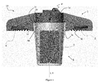
- FIG. 1 is a cross-sectional view of the luminaire 10 according to a preferred embodiment of the invention.
- the luminaire 10 of the preferred embodiment is a luminaire for being operated with a high lumen output and/or in environments having a high ambient temperature.
- the luminaire 10 has a main beam direction B.
- the luminaire 10 comprises a heatsink 1.
- the heatsink 1 has a substantially round and symmetrical shape.
- the heatsink 1 is, however, not restricted to a particular shape.
- the heatsink 1 has such a shape that its surface is increased for facilitating heat flow.
- Increasing the surface of the heatsink may be achieved by (integrally) providing cooling fins 1g with the heatsink 1, which are preferably evenly distributed over the circumference of the heatsink 1.
- the cooling fins 1g may extend radially and may be arranged annularly with respect to the main beam direction B.
- the cooling fins 1g constitute a lattice-like heatsink 1, thus providing an increased surface of the heatsink 1 for facilitating cooling.
- the luminaire 10 further comprises a light source 2 mounted to the heatsink 1.
- the light source 2 is preferably mounted to the heatsink 1 by means of a receiving groove 1d that extends in the heatsink 1 preferably around the main beam direction B and receives the light source 2.
- the receiving groove 1d extends in the plurality of cooling fins 1g.
- the cooling fins 1g preferably receive the light source 2.
- the light source 2 may have a substantially two-dimensional extension.
- the light source 2 may be an LED module.
- the LED-module may be in plane contact with the heatsink 1.
- the LED module may comprise at least one LED and/or printed circuit board (PCB).
- the at least on LED is bonded to the printed circuit board.
- the luminaire 10 comprises a driver 3 configured to drive the light source 2.
- the whole driver 3 is positioned on the side of the light source 2 being opposite to the heatsink 1.
- the driver 3 is at least partially positioned on the side of the light source 2 being opposite to the heatsink 1 in order to achieve the inventive effect.
- the light source 2 defines a plane and/or extends in a plane sandwiched between the heatsink 1 and the light emitting side, wherein the side of the light source 2 being opposite to the heatsink 1 faces towards the light emitting side. Under consideration of this plane, the driver 3 protrudes at least partially from the plane to the light emitting side.
- the majority of the driver 3 is positioned on the side of the light source 2 being opposite to the heatsink 1.
- the majority may relate to, e.g., the volume of the driver 3, the weight of the driver 3 or the number of (electronic and/or mechanical) components constituting the driver 3.
- the driver 3 may also be positioned with respect to the heatsink 1, such that (only) a part of the driver 3 being the most critical part of the driver 3 with respect to heat flow is positioned on the side of the light source 2 being opposite to the heatsink 1. Said part may be defined as the tc point.
- further electric and/or electronic components such as an energy source, preferably a battery, and/or further means for controlling the light source 2 may be positioned with respect to the heatsink 1 in the same way as described previously for the driver 3.
- the further components may be positioned on a side of the driver 3 being opposite to the heatsink 1 and the light source 2, i.e. farther away from the heatsink 1 than the driver 3.
- the battery may be positioned farther away from the heatsink 1 than the driver 3, preferably below the driver 3. This ensures that the temperature of the battery is only influenced by the ambient temperature.
- the further components respectively, may have a tc point, wherein said tc point is also positioned on the side of the light source 2 being opposite to the heatsink 1.
- the driver 3 may extend longitudinally, preferably have an elongated shape, particularly preferably a cylindrical shape, with a longitudinal axis L, wherein the axis L is parallel or preferably flush with the main beam direction B of the luminaire 10.
- the axis L is substantially perpendicular to the plane defined by the light source 2.
- the longitudinal axis L may also be angled and preferably orientated substantially perpendicular with respect to the main beam direction B, i.e. preferably substantially in parallel with respect to the plane defined by the light source 2.
- the driver 3 when viewed in the main beam direction B, i.e. from below in the direction of the light source 2 and heatsink 1 in Figure 1 , the driver 3 may also be positioned at least partially within or outside the periphery of the heatsink 1.
- the exemplary heatsink 1 of the luminaire 10 in Figure 10 further comprises a hole 1a having an opening on the side of the light source 2.
- the hole 1a is positioned substantially in the center of the heatsink 1.
- the extending axis of the hole 1a may be parallel or preferably flush with the main beam direction B.
- the longitudinal axis L of the driver 3 may be parallel or preferably flush with the extending axis of the hole 1a.
- the driver 3 may extend in the hole 1a and may optionally be mounted to the heatsink 1 by means of the hole 1a.
- the hole 1a has a tapering shape that tapers in a direction away from the light source 2 or the side of the light source 2 being opposite to the heatsink 1.
- tapering of the hole 1a may be constituted by a stepwise form of the hole 1a.
- the hole 1a may also be provided as a hole that tapers by gradually increasing its diameter or by partially increasing its diameter gradually and by partially increasing its diameter stepwisely.
- the latter option can be seen in Figure 1 , where a first part of the hole 1a being on the side of the light source 2 increases gradually, wherein the other part of the hole 1a is connected to the first part of the hole 1a via a step 1c.
- step 1c can also be provided without the aforementioned form of the hole 1a.
- the luminaire may comprise a housing 5 for enclosing and preferably holding the driver 3. Holding the driver 3 may be carried out by holding elements (not shown) provided in the housing 5.
- the housing 5 is designed for further enclosing and optionally holding the further components, i.e. the energy source, e.g. a battery, and/or the further electronic and/or electric components.
- the housing 5 may be mounted to the heatsink 1 my means of a corresponding connection between the hole 1a and the housing 5, such as an engagement of corresponding connection means, a transition fit, a snap fit or the like.
- the housing may be mounted to the heatsink 1 by means of fixing elements, such as bolts, nuts or the like.
- the housing 5 comprises an opening 5a facing towards the heatsink 1.
- the opening 5a may face the hole 1a of the heatsink 1.
- the driver 3 may extent through the opening 5a into the hole 1a.
- the housing 5 has a substantially cylindrical shape that tapers in a direction away from the heatsink 1, i.e. a substantially cone-shaped form.
- the housing may also have a different shape, such as a rectangular shape or the like.
- the end of the housing 5 facing towards the heatsink 1 may be held by the hole 1a of the heatsink 1.
- Said end may comprise a rim 5b that is preferably received by a connection groove 1b extending in the step 1c of the hole 1a.
- the connection groove 1b may further comprise engaging elements for engagement of the housing 5.
- the housing 5 in Figure 1 comprises a plurality of cooling fins 5c.
- the cooling fins 5c may be evenly distributed over the circumference of the housing 5.
- the cooling fins 5c may extend from the opening 5b of the housing 5 in the extending direction of the housing 5, preferably away from the heatsink 1, substantially in the direction of the main beam direction B.
- the longitudinal axis L As viewed perpendicular to the extending direction of the housing 5, the longitudinal axis L, respectively, the cooling fins 5c may be wedge-shaped.
- the cooling-fins 5c may also have any different shape, such as a rectangular shape or the like, that increases the total surface of the housing 5 for facilitating cooling of the components enclosed in the housing 5.
- the plurality of cooling fins 5c may engage with the hole 1a of the heatsink 1 for mounting the housing 5 on the heatsink 1.
- This arrangement also provides a heat flow from the housing 5 by way of the cooling fins 5c to the heatsink 1.
- the hole 1a of the heatsink 1 comprises recesses 1e, in particular slots, corresponding to the shape and preferably to the number of the plurality of cooling fins 5c for engagement of the cooling fins 5c with the hole 1a.
- the cooling fins 5b may abut the step 1c of the hole 1a on the face side of the cooling fins 5b.
- the cooling fins 1g of the heatsink 1 and the cooling fins 5c of the housing 5 may thermally cooperate with each other, e.g. by extending longitudinally from one another, to form a combined cooling body.
- the housing 5 may also be integrally formed with the heatsink 1.
- the material of the housing 5 and the cooling fins 5c, respectively, has a high thermal conductivity for facilitating cooling.
- the material of the housing 5 is metal.
- the material of the heatsink 1 may also have a high thermal conductivity for facilitating cooling, such as metal or the like.
- the luminaire 10 may further comprise an optical system 4 provided on the side of the light source 2 being opposite to the heatsink 1 for interacting with the light emitted by the light source 2.
- the optical system 2 may influence the emitted light to constitute the main beam direction B.
- the optical system 2 may be connected to, preferably mounted on, the heatsink 1.
- the optical system 4 may cover the receiving groove 1d, and thus preferably also covers the light source 2.
- the optical system 4 may also be provided/placed within the receiving groove 1d, i.e. the optical system 4 may be received by the receiving groove 1d and may cover the light source 2.
- the heatsink 1 may comprise attaching elements 1f for attaching the luminaire, e.g. at a housing, a ceiling, a wall etc.
- the attaching elements 1f are preferably provided on a side of the heatsink 1 being opposite to the side of the heatsink 1, where the light source 2 is mounted.
- Figure 2 shows the temperature on air while the luminaire 10 is operated. It is apparent that the heat plume H does not influence the temperature of the driver 3.
- the region inside the hole 1a constitutes a relatively hot region. Furthermore, it can be seen that heat generated by the light source 2 is flowing away from light source 2 by way of the heatsink 1 and further away from the heatsink 1.
Landscapes
- Engineering & Computer Science (AREA)
- General Engineering & Computer Science (AREA)
- Microelectronics & Electronic Packaging (AREA)
- Non-Portable Lighting Devices Or Systems Thereof (AREA)
- Arrangement Of Elements, Cooling, Sealing, Or The Like Of Lighting Devices (AREA)
Priority Applications (1)
| Application Number | Priority Date | Filing Date | Title |
|---|---|---|---|
| EP16182513.8A EP3279558B1 (de) | 2016-08-03 | 2016-08-03 | Leuchte |
Applications Claiming Priority (1)
| Application Number | Priority Date | Filing Date | Title |
|---|---|---|---|
| EP16182513.8A EP3279558B1 (de) | 2016-08-03 | 2016-08-03 | Leuchte |
Publications (2)
| Publication Number | Publication Date |
|---|---|
| EP3279558A1 true EP3279558A1 (de) | 2018-02-07 |
| EP3279558B1 EP3279558B1 (de) | 2019-01-02 |
Family
ID=56801376
Family Applications (1)
| Application Number | Title | Priority Date | Filing Date |
|---|---|---|---|
| EP16182513.8A Active EP3279558B1 (de) | 2016-08-03 | 2016-08-03 | Leuchte |
Country Status (1)
| Country | Link |
|---|---|
| EP (1) | EP3279558B1 (de) |
Families Citing this family (1)
| Publication number | Priority date | Publication date | Assignee | Title |
|---|---|---|---|---|
| IT202200005645A1 (it) * | 2022-03-22 | 2023-09-22 | Cortem S P A | Apparato di illuminazione e relativo procedimento d’uso |
Citations (7)
| Publication number | Priority date | Publication date | Assignee | Title |
|---|---|---|---|---|
| US20090147510A1 (en) * | 2007-12-07 | 2009-06-11 | Chang-Hung Peng | Led illumination device and illumination module using the same |
| US20110032696A1 (en) * | 2009-08-04 | 2011-02-10 | Min Kong Kim | Led lighting lamp |
| US20110101861A1 (en) * | 2009-10-30 | 2011-05-05 | Young Ho Yoo | Led lamp |
| US20110316014A1 (en) * | 2010-06-29 | 2011-12-29 | Rohm Co., Ltd. | Led module and led lighting device |
| US20130044478A1 (en) * | 2011-08-15 | 2013-02-21 | MaxLite, Inc. | Led illumination device with isolated driving circuitry |
| US20140204562A1 (en) * | 2013-01-22 | 2014-07-24 | Panasonic Corporation | Illumination light source and lighting apparatus |
| WO2015031322A1 (en) * | 2013-08-26 | 2015-03-05 | Delta T Corporation | Tunable luminaire and related methods to control light output |
-
2016
- 2016-08-03 EP EP16182513.8A patent/EP3279558B1/de active Active
Patent Citations (7)
| Publication number | Priority date | Publication date | Assignee | Title |
|---|---|---|---|---|
| US20090147510A1 (en) * | 2007-12-07 | 2009-06-11 | Chang-Hung Peng | Led illumination device and illumination module using the same |
| US20110032696A1 (en) * | 2009-08-04 | 2011-02-10 | Min Kong Kim | Led lighting lamp |
| US20110101861A1 (en) * | 2009-10-30 | 2011-05-05 | Young Ho Yoo | Led lamp |
| US20110316014A1 (en) * | 2010-06-29 | 2011-12-29 | Rohm Co., Ltd. | Led module and led lighting device |
| US20130044478A1 (en) * | 2011-08-15 | 2013-02-21 | MaxLite, Inc. | Led illumination device with isolated driving circuitry |
| US20140204562A1 (en) * | 2013-01-22 | 2014-07-24 | Panasonic Corporation | Illumination light source and lighting apparatus |
| WO2015031322A1 (en) * | 2013-08-26 | 2015-03-05 | Delta T Corporation | Tunable luminaire and related methods to control light output |
Also Published As
| Publication number | Publication date |
|---|---|
| EP3279558B1 (de) | 2019-01-02 |
Similar Documents
| Publication | Publication Date | Title |
|---|---|---|
| EP2256403B1 (de) | LED-Lampe mit Vorschaltgerät | |
| EP2569576B1 (de) | Beleuchtungsmodul | |
| EP2228595B1 (de) | LED-Lampeneinheit | |
| US7663229B2 (en) | Lighting device | |
| EP2228587B1 (de) | Led-glühlampe und beleuchtungsvorrichtung | |
| US20170184261A1 (en) | Electrical connection of control circuit card to power supply in led luminaire assembly | |
| JP2010277910A5 (de) | ||
| JP6271264B2 (ja) | 光源ユニット、および車両用照明装置 | |
| EP2633226B1 (de) | Beleuchtungsanordnung | |
| EP3279558B1 (de) | Leuchte | |
| US12152753B2 (en) | Lamp | |
| JP2019053940A (ja) | Led前照灯 | |
| JP2012119230A (ja) | Ledランプおよびled照明装置 | |
| EP3290790B1 (de) | Kühlkörper | |
| KR20110139466A (ko) | Led 조명기구 및 그 제조방법 | |
| US9279548B1 (en) | Light collimating assembly with dual horns | |
| EP3839333B1 (de) | Leuchtenabdeckung | |
| JP6171215B2 (ja) | Ledランプ | |
| EP3387322B1 (de) | Verbesserter deckenstrahler | |
| CN103069215B (zh) | 具有高光学精度的可替换发光二极管模块 | |
| JP2016085788A (ja) | 照明装置 |
Legal Events
| Date | Code | Title | Description |
|---|---|---|---|
| PUAI | Public reference made under article 153(3) epc to a published international application that has entered the european phase |
Free format text: ORIGINAL CODE: 0009012 |
|
| STAA | Information on the status of an ep patent application or granted ep patent |
Free format text: STATUS: THE APPLICATION HAS BEEN PUBLISHED |
|
| AK | Designated contracting states |
Kind code of ref document: A1 Designated state(s): AL AT BE BG CH CY CZ DE DK EE ES FI FR GB GR HR HU IE IS IT LI LT LU LV MC MK MT NL NO PL PT RO RS SE SI SK SM TR |
|
| AX | Request for extension of the european patent |
Extension state: BA ME |
|
| STAA | Information on the status of an ep patent application or granted ep patent |
Free format text: STATUS: REQUEST FOR EXAMINATION WAS MADE |
|
| 17P | Request for examination filed |
Effective date: 20180416 |
|
| RBV | Designated contracting states (corrected) |
Designated state(s): AL AT BE BG CH CY CZ DE DK EE ES FI FR GB GR HR HU IE IS IT LI LT LU LV MC MK MT NL NO PL PT RO RS SE SI SK SM TR |
|
| RIC1 | Information provided on ipc code assigned before grant |
Ipc: F21V 15/01 20060101ALN20180807BHEP Ipc: F21V 29/77 20150101ALI20180807BHEP Ipc: F21Y 105/18 20160101ALN20180807BHEP Ipc: F21S 8/04 20060101ALN20180807BHEP Ipc: F21Y 115/10 20160101ALN20180807BHEP Ipc: F21W 131/103 20060101ALN20180807BHEP Ipc: F21S 9/02 20060101ALN20180807BHEP Ipc: F21V 23/00 20150101AFI20180807BHEP |
|
| GRAP | Despatch of communication of intention to grant a patent |
Free format text: ORIGINAL CODE: EPIDOSNIGR1 |
|
| STAA | Information on the status of an ep patent application or granted ep patent |
Free format text: STATUS: GRANT OF PATENT IS INTENDED |
|
| RIC1 | Information provided on ipc code assigned before grant |
Ipc: F21W 131/103 20060101ALN20180823BHEP Ipc: F21S 9/02 20060101ALN20180823BHEP Ipc: F21Y 115/10 20160101ALN20180823BHEP Ipc: F21V 23/00 20150101AFI20180823BHEP Ipc: F21S 8/04 20060101ALN20180823BHEP Ipc: F21V 29/77 20150101ALI20180823BHEP Ipc: F21V 15/01 20060101ALN20180823BHEP Ipc: F21Y 105/18 20160101ALN20180823BHEP |
|
| INTG | Intention to grant announced |
Effective date: 20180918 |
|
| GRAS | Grant fee paid |
Free format text: ORIGINAL CODE: EPIDOSNIGR3 |
|
| GRAA | (expected) grant |
Free format text: ORIGINAL CODE: 0009210 |
|
| STAA | Information on the status of an ep patent application or granted ep patent |
Free format text: STATUS: THE PATENT HAS BEEN GRANTED |
|
| AK | Designated contracting states |
Kind code of ref document: B1 Designated state(s): AL AT BE BG CH CY CZ DE DK EE ES FI FR GB GR HR HU IE IS IT LI LT LU LV MC MK MT NL NO PL PT RO RS SE SI SK SM TR |
|
| REG | Reference to a national code |
Ref country code: GB Ref legal event code: FG4D |
|
| REG | Reference to a national code |
Ref country code: CH Ref legal event code: EP Ref country code: CH Ref legal event code: NV Representative=s name: FELBER UND PARTNER AG, CH Ref country code: AT Ref legal event code: REF Ref document number: 1084850 Country of ref document: AT Kind code of ref document: T Effective date: 20190115 |
|
| REG | Reference to a national code |
Ref country code: IE Ref legal event code: FG4D |
|
| REG | Reference to a national code |
Ref country code: DE Ref legal event code: R096 Ref document number: 602016008880 Country of ref document: DE |
|
| REG | Reference to a national code |
Ref country code: NL Ref legal event code: MP Effective date: 20190102 |
|
| REG | Reference to a national code |
Ref country code: LT Ref legal event code: MG4D |
|
| PG25 | Lapsed in a contracting state [announced via postgrant information from national office to epo] |
Ref country code: NL Free format text: LAPSE BECAUSE OF FAILURE TO SUBMIT A TRANSLATION OF THE DESCRIPTION OR TO PAY THE FEE WITHIN THE PRESCRIBED TIME-LIMIT Effective date: 20190102 |
|
| PG25 | Lapsed in a contracting state [announced via postgrant information from national office to epo] |
Ref country code: NO Free format text: LAPSE BECAUSE OF FAILURE TO SUBMIT A TRANSLATION OF THE DESCRIPTION OR TO PAY THE FEE WITHIN THE PRESCRIBED TIME-LIMIT Effective date: 20190402 Ref country code: ES Free format text: LAPSE BECAUSE OF FAILURE TO SUBMIT A TRANSLATION OF THE DESCRIPTION OR TO PAY THE FEE WITHIN THE PRESCRIBED TIME-LIMIT Effective date: 20190102 Ref country code: LT Free format text: LAPSE BECAUSE OF FAILURE TO SUBMIT A TRANSLATION OF THE DESCRIPTION OR TO PAY THE FEE WITHIN THE PRESCRIBED TIME-LIMIT Effective date: 20190102 Ref country code: PL Free format text: LAPSE BECAUSE OF FAILURE TO SUBMIT A TRANSLATION OF THE DESCRIPTION OR TO PAY THE FEE WITHIN THE PRESCRIBED TIME-LIMIT Effective date: 20190102 Ref country code: SE Free format text: LAPSE BECAUSE OF FAILURE TO SUBMIT A TRANSLATION OF THE DESCRIPTION OR TO PAY THE FEE WITHIN THE PRESCRIBED TIME-LIMIT Effective date: 20190102 Ref country code: PT Free format text: LAPSE BECAUSE OF FAILURE TO SUBMIT A TRANSLATION OF THE DESCRIPTION OR TO PAY THE FEE WITHIN THE PRESCRIBED TIME-LIMIT Effective date: 20190502 Ref country code: FI Free format text: LAPSE BECAUSE OF FAILURE TO SUBMIT A TRANSLATION OF THE DESCRIPTION OR TO PAY THE FEE WITHIN THE PRESCRIBED TIME-LIMIT Effective date: 20190102 |
|
| PG25 | Lapsed in a contracting state [announced via postgrant information from national office to epo] |
Ref country code: HR Free format text: LAPSE BECAUSE OF FAILURE TO SUBMIT A TRANSLATION OF THE DESCRIPTION OR TO PAY THE FEE WITHIN THE PRESCRIBED TIME-LIMIT Effective date: 20190102 Ref country code: RS Free format text: LAPSE BECAUSE OF FAILURE TO SUBMIT A TRANSLATION OF THE DESCRIPTION OR TO PAY THE FEE WITHIN THE PRESCRIBED TIME-LIMIT Effective date: 20190102 Ref country code: LV Free format text: LAPSE BECAUSE OF FAILURE TO SUBMIT A TRANSLATION OF THE DESCRIPTION OR TO PAY THE FEE WITHIN THE PRESCRIBED TIME-LIMIT Effective date: 20190102 Ref country code: BG Free format text: LAPSE BECAUSE OF FAILURE TO SUBMIT A TRANSLATION OF THE DESCRIPTION OR TO PAY THE FEE WITHIN THE PRESCRIBED TIME-LIMIT Effective date: 20190402 Ref country code: IS Free format text: LAPSE BECAUSE OF FAILURE TO SUBMIT A TRANSLATION OF THE DESCRIPTION OR TO PAY THE FEE WITHIN THE PRESCRIBED TIME-LIMIT Effective date: 20190502 Ref country code: GR Free format text: LAPSE BECAUSE OF FAILURE TO SUBMIT A TRANSLATION OF THE DESCRIPTION OR TO PAY THE FEE WITHIN THE PRESCRIBED TIME-LIMIT Effective date: 20190403 |
|
| REG | Reference to a national code |
Ref country code: DE Ref legal event code: R097 Ref document number: 602016008880 Country of ref document: DE |
|
| PG25 | Lapsed in a contracting state [announced via postgrant information from national office to epo] |
Ref country code: EE Free format text: LAPSE BECAUSE OF FAILURE TO SUBMIT A TRANSLATION OF THE DESCRIPTION OR TO PAY THE FEE WITHIN THE PRESCRIBED TIME-LIMIT Effective date: 20190102 Ref country code: DK Free format text: LAPSE BECAUSE OF FAILURE TO SUBMIT A TRANSLATION OF THE DESCRIPTION OR TO PAY THE FEE WITHIN THE PRESCRIBED TIME-LIMIT Effective date: 20190102 Ref country code: AL Free format text: LAPSE BECAUSE OF FAILURE TO SUBMIT A TRANSLATION OF THE DESCRIPTION OR TO PAY THE FEE WITHIN THE PRESCRIBED TIME-LIMIT Effective date: 20190102 Ref country code: SK Free format text: LAPSE BECAUSE OF FAILURE TO SUBMIT A TRANSLATION OF THE DESCRIPTION OR TO PAY THE FEE WITHIN THE PRESCRIBED TIME-LIMIT Effective date: 20190102 Ref country code: IT Free format text: LAPSE BECAUSE OF FAILURE TO SUBMIT A TRANSLATION OF THE DESCRIPTION OR TO PAY THE FEE WITHIN THE PRESCRIBED TIME-LIMIT Effective date: 20190102 Ref country code: RO Free format text: LAPSE BECAUSE OF FAILURE TO SUBMIT A TRANSLATION OF THE DESCRIPTION OR TO PAY THE FEE WITHIN THE PRESCRIBED TIME-LIMIT Effective date: 20190102 Ref country code: CZ Free format text: LAPSE BECAUSE OF FAILURE TO SUBMIT A TRANSLATION OF THE DESCRIPTION OR TO PAY THE FEE WITHIN THE PRESCRIBED TIME-LIMIT Effective date: 20190102 |
|
| PLBE | No opposition filed within time limit |
Free format text: ORIGINAL CODE: 0009261 |
|
| STAA | Information on the status of an ep patent application or granted ep patent |
Free format text: STATUS: NO OPPOSITION FILED WITHIN TIME LIMIT |
|
| PG25 | Lapsed in a contracting state [announced via postgrant information from national office to epo] |
Ref country code: SM Free format text: LAPSE BECAUSE OF FAILURE TO SUBMIT A TRANSLATION OF THE DESCRIPTION OR TO PAY THE FEE WITHIN THE PRESCRIBED TIME-LIMIT Effective date: 20190102 |
|
| 26N | No opposition filed |
Effective date: 20191003 |
|
| PG25 | Lapsed in a contracting state [announced via postgrant information from national office to epo] |
Ref country code: SI Free format text: LAPSE BECAUSE OF FAILURE TO SUBMIT A TRANSLATION OF THE DESCRIPTION OR TO PAY THE FEE WITHIN THE PRESCRIBED TIME-LIMIT Effective date: 20190102 |
|
| PG25 | Lapsed in a contracting state [announced via postgrant information from national office to epo] |
Ref country code: TR Free format text: LAPSE BECAUSE OF FAILURE TO SUBMIT A TRANSLATION OF THE DESCRIPTION OR TO PAY THE FEE WITHIN THE PRESCRIBED TIME-LIMIT Effective date: 20190102 |
|
| PG25 | Lapsed in a contracting state [announced via postgrant information from national office to epo] |
Ref country code: LU Free format text: LAPSE BECAUSE OF NON-PAYMENT OF DUE FEES Effective date: 20190803 Ref country code: MC Free format text: LAPSE BECAUSE OF FAILURE TO SUBMIT A TRANSLATION OF THE DESCRIPTION OR TO PAY THE FEE WITHIN THE PRESCRIBED TIME-LIMIT Effective date: 20190102 |
|
| REG | Reference to a national code |
Ref country code: BE Ref legal event code: MM Effective date: 20190831 |
|
| PG25 | Lapsed in a contracting state [announced via postgrant information from national office to epo] |
Ref country code: IE Free format text: LAPSE BECAUSE OF NON-PAYMENT OF DUE FEES Effective date: 20190803 |
|
| PG25 | Lapsed in a contracting state [announced via postgrant information from national office to epo] |
Ref country code: BE Free format text: LAPSE BECAUSE OF NON-PAYMENT OF DUE FEES Effective date: 20190831 |
|
| REG | Reference to a national code |
Ref country code: AT Ref legal event code: UEP Ref document number: 1084850 Country of ref document: AT Kind code of ref document: T Effective date: 20190102 |
|
| PG25 | Lapsed in a contracting state [announced via postgrant information from national office to epo] |
Ref country code: CY Free format text: LAPSE BECAUSE OF FAILURE TO SUBMIT A TRANSLATION OF THE DESCRIPTION OR TO PAY THE FEE WITHIN THE PRESCRIBED TIME-LIMIT Effective date: 20190102 |
|
| PG25 | Lapsed in a contracting state [announced via postgrant information from national office to epo] |
Ref country code: HU Free format text: LAPSE BECAUSE OF FAILURE TO SUBMIT A TRANSLATION OF THE DESCRIPTION OR TO PAY THE FEE WITHIN THE PRESCRIBED TIME-LIMIT; INVALID AB INITIO Effective date: 20160803 Ref country code: MT Free format text: LAPSE BECAUSE OF FAILURE TO SUBMIT A TRANSLATION OF THE DESCRIPTION OR TO PAY THE FEE WITHIN THE PRESCRIBED TIME-LIMIT Effective date: 20190102 |
|
| PG25 | Lapsed in a contracting state [announced via postgrant information from national office to epo] |
Ref country code: MK Free format text: LAPSE BECAUSE OF FAILURE TO SUBMIT A TRANSLATION OF THE DESCRIPTION OR TO PAY THE FEE WITHIN THE PRESCRIBED TIME-LIMIT Effective date: 20190102 |
|
| REG | Reference to a national code |
Ref country code: AT Ref legal event code: MM01 Ref document number: 1084850 Country of ref document: AT Kind code of ref document: T Effective date: 20210803 |
|
| PG25 | Lapsed in a contracting state [announced via postgrant information from national office to epo] |
Ref country code: AT Free format text: LAPSE BECAUSE OF NON-PAYMENT OF DUE FEES Effective date: 20210803 |
|
| P01 | Opt-out of the competence of the unified patent court (upc) registered |
Effective date: 20230530 |
|
| REG | Reference to a national code |
Ref country code: DE Ref legal event code: R084 Ref document number: 602016008880 Country of ref document: DE |
|
| PGFP | Annual fee paid to national office [announced via postgrant information from national office to epo] |
Ref country code: GB Payment date: 20230822 Year of fee payment: 8 Ref country code: CH Payment date: 20230902 Year of fee payment: 8 |
|
| PGFP | Annual fee paid to national office [announced via postgrant information from national office to epo] |
Ref country code: FR Payment date: 20230824 Year of fee payment: 8 |
|
| PGFP | Annual fee paid to national office [announced via postgrant information from national office to epo] |
Ref country code: DE Payment date: 20240828 Year of fee payment: 9 |
|
| REG | Reference to a national code |
Ref country code: CH Ref legal event code: PL |
|
| GBPC | Gb: european patent ceased through non-payment of renewal fee |
Effective date: 20240803 |
|
| PG25 | Lapsed in a contracting state [announced via postgrant information from national office to epo] |
Ref country code: CH Free format text: LAPSE BECAUSE OF NON-PAYMENT OF DUE FEES Effective date: 20240831 |
|
| PG25 | Lapsed in a contracting state [announced via postgrant information from national office to epo] |
Ref country code: GB Free format text: LAPSE BECAUSE OF NON-PAYMENT OF DUE FEES Effective date: 20240803 |
|
| PG25 | Lapsed in a contracting state [announced via postgrant information from national office to epo] |
Ref country code: FR Free format text: LAPSE BECAUSE OF NON-PAYMENT OF DUE FEES Effective date: 20240831 |
|
| REG | Reference to a national code |
Ref country code: DE Ref legal event code: R119 Ref document number: 602016008880 Country of ref document: DE |