EP3280132B1 - Dispositif de traitement d'images, dispositif de capture d'images, programme et support de stockage - Google Patents
Dispositif de traitement d'images, dispositif de capture d'images, programme et support de stockage Download PDFInfo
- Publication number
- EP3280132B1 EP3280132B1 EP16772954.0A EP16772954A EP3280132B1 EP 3280132 B1 EP3280132 B1 EP 3280132B1 EP 16772954 A EP16772954 A EP 16772954A EP 3280132 B1 EP3280132 B1 EP 3280132B1
- Authority
- EP
- European Patent Office
- Prior art keywords
- light
- modulation
- frequency
- section
- pixel
- Prior art date
- Legal status (The legal status is an assumption and is not a legal conclusion. Google has not performed a legal analysis and makes no representation as to the accuracy of the status listed.)
- Active
Links
Images


Classifications
-
- H—ELECTRICITY
- H10—SEMICONDUCTOR DEVICES; ELECTRIC SOLID-STATE DEVICES NOT OTHERWISE PROVIDED FOR
- H10F—INORGANIC SEMICONDUCTOR DEVICES SENSITIVE TO INFRARED RADIATION, LIGHT, ELECTROMAGNETIC RADIATION OF SHORTER WAVELENGTH OR CORPUSCULAR RADIATION
- H10F39/00—Integrated devices, or assemblies of multiple devices, comprising at least one element covered by group H10F30/00, e.g. radiation detectors comprising photodiode arrays
- H10F39/10—Integrated devices
- H10F39/12—Image sensors
- H10F39/199—Back-illuminated image sensors
-
- A—HUMAN NECESSITIES
- A61—MEDICAL OR VETERINARY SCIENCE; HYGIENE
- A61B—DIAGNOSIS; SURGERY; IDENTIFICATION
- A61B1/00—Instruments for performing medical examinations of the interior of cavities or tubes of the body by visual or photographical inspection, e.g. endoscopes; Illuminating arrangements therefor
- A61B1/00002—Operational features of endoscopes
- A61B1/00004—Operational features of endoscopes characterised by electronic signal processing
- A61B1/00009—Operational features of endoscopes characterised by electronic signal processing of image signals during a use of endoscope
-
- A—HUMAN NECESSITIES
- A61—MEDICAL OR VETERINARY SCIENCE; HYGIENE
- A61B—DIAGNOSIS; SURGERY; IDENTIFICATION
- A61B1/00—Instruments for performing medical examinations of the interior of cavities or tubes of the body by visual or photographical inspection, e.g. endoscopes; Illuminating arrangements therefor
- A61B1/06—Instruments for performing medical examinations of the interior of cavities or tubes of the body by visual or photographical inspection, e.g. endoscopes; Illuminating arrangements therefor with illuminating arrangements
- A61B1/0638—Instruments for performing medical examinations of the interior of cavities or tubes of the body by visual or photographical inspection, e.g. endoscopes; Illuminating arrangements therefor with illuminating arrangements providing two or more wavelengths
-
- A—HUMAN NECESSITIES
- A61—MEDICAL OR VETERINARY SCIENCE; HYGIENE
- A61B—DIAGNOSIS; SURGERY; IDENTIFICATION
- A61B1/00—Instruments for performing medical examinations of the interior of cavities or tubes of the body by visual or photographical inspection, e.g. endoscopes; Illuminating arrangements therefor
- A61B1/06—Instruments for performing medical examinations of the interior of cavities or tubes of the body by visual or photographical inspection, e.g. endoscopes; Illuminating arrangements therefor with illuminating arrangements
- A61B1/0661—Endoscope light sources
- A61B1/0684—Endoscope light sources using light emitting diodes [LED]
-
- A—HUMAN NECESSITIES
- A61—MEDICAL OR VETERINARY SCIENCE; HYGIENE
- A61B—DIAGNOSIS; SURGERY; IDENTIFICATION
- A61B1/00—Instruments for performing medical examinations of the interior of cavities or tubes of the body by visual or photographical inspection, e.g. endoscopes; Illuminating arrangements therefor
- A61B1/313—Instruments for performing medical examinations of the interior of cavities or tubes of the body by visual or photographical inspection, e.g. endoscopes; Illuminating arrangements therefor for introducing through surgical openings, e.g. laparoscopes
- A61B1/3132—Instruments for performing medical examinations of the interior of cavities or tubes of the body by visual or photographical inspection, e.g. endoscopes; Illuminating arrangements therefor for introducing through surgical openings, e.g. laparoscopes for laparoscopy
-
- G—PHYSICS
- G06—COMPUTING OR CALCULATING; COUNTING
- G06T—IMAGE DATA PROCESSING OR GENERATION, IN GENERAL
- G06T1/00—General purpose image data processing
-
- H—ELECTRICITY
- H04—ELECTRIC COMMUNICATION TECHNIQUE
- H04N—PICTORIAL COMMUNICATION, e.g. TELEVISION
- H04N1/00—Scanning, transmission or reproduction of documents or the like, e.g. facsimile transmission; Details thereof
- H04N1/46—Colour picture communication systems
- H04N1/48—Picture signal generators
- H04N1/482—Picture signal generators using the same detector device sequentially for different colour components
- H04N1/484—Picture signal generators using the same detector device sequentially for different colour components with sequential colour illumination of the original
-
- H—ELECTRICITY
- H04—ELECTRIC COMMUNICATION TECHNIQUE
- H04N—PICTORIAL COMMUNICATION, e.g. TELEVISION
- H04N23/00—Cameras or camera modules comprising electronic image sensors; Control thereof
- H04N23/10—Cameras or camera modules comprising electronic image sensors; Control thereof for generating image signals from different wavelengths
- H04N23/12—Cameras or camera modules comprising electronic image sensors; Control thereof for generating image signals from different wavelengths with one sensor only
-
- H—ELECTRICITY
- H04—ELECTRIC COMMUNICATION TECHNIQUE
- H04N—PICTORIAL COMMUNICATION, e.g. TELEVISION
- H04N23/00—Cameras or camera modules comprising electronic image sensors; Control thereof
- H04N23/10—Cameras or camera modules comprising electronic image sensors; Control thereof for generating image signals from different wavelengths
- H04N23/125—Colour sequential image capture, e.g. using a colour wheel
-
- H—ELECTRICITY
- H04—ELECTRIC COMMUNICATION TECHNIQUE
- H04N—PICTORIAL COMMUNICATION, e.g. TELEVISION
- H04N23/00—Cameras or camera modules comprising electronic image sensors; Control thereof
- H04N23/56—Cameras or camera modules comprising electronic image sensors; Control thereof provided with illuminating means
-
- H—ELECTRICITY
- H04—ELECTRIC COMMUNICATION TECHNIQUE
- H04N—PICTORIAL COMMUNICATION, e.g. TELEVISION
- H04N23/00—Cameras or camera modules comprising electronic image sensors; Control thereof
- H04N23/60—Control of cameras or camera modules
-
- H—ELECTRICITY
- H04—ELECTRIC COMMUNICATION TECHNIQUE
- H04N—PICTORIAL COMMUNICATION, e.g. TELEVISION
- H04N23/00—Cameras or camera modules comprising electronic image sensors; Control thereof
- H04N23/70—Circuitry for compensating brightness variation in the scene
- H04N23/71—Circuitry for evaluating the brightness variation
-
- H—ELECTRICITY
- H04—ELECTRIC COMMUNICATION TECHNIQUE
- H04N—PICTORIAL COMMUNICATION, e.g. TELEVISION
- H04N23/00—Cameras or camera modules comprising electronic image sensors; Control thereof
- H04N23/70—Circuitry for compensating brightness variation in the scene
- H04N23/74—Circuitry for compensating brightness variation in the scene by influencing the scene brightness using illuminating means
-
- H—ELECTRICITY
- H04—ELECTRIC COMMUNICATION TECHNIQUE
- H04N—PICTORIAL COMMUNICATION, e.g. TELEVISION
- H04N23/00—Cameras or camera modules comprising electronic image sensors; Control thereof
- H04N23/70—Circuitry for compensating brightness variation in the scene
- H04N23/75—Circuitry for compensating brightness variation in the scene by influencing optical camera components
-
- H—ELECTRICITY
- H04—ELECTRIC COMMUNICATION TECHNIQUE
- H04N—PICTORIAL COMMUNICATION, e.g. TELEVISION
- H04N25/00—Circuitry of solid-state image sensors [SSIS]; Control thereof
- H04N25/40—Extracting pixel data from image sensors by controlling scanning circuits, e.g. by modifying the number of pixels sampled or to be sampled
-
- H—ELECTRICITY
- H04—ELECTRIC COMMUNICATION TECHNIQUE
- H04N—PICTORIAL COMMUNICATION, e.g. TELEVISION
- H04N25/00—Circuitry of solid-state image sensors [SSIS]; Control thereof
- H04N25/50—Control of the SSIS exposure
-
- H—ELECTRICITY
- H10—SEMICONDUCTOR DEVICES; ELECTRIC SOLID-STATE DEVICES NOT OTHERWISE PROVIDED FOR
- H10F—INORGANIC SEMICONDUCTOR DEVICES SENSITIVE TO INFRARED RADIATION, LIGHT, ELECTROMAGNETIC RADIATION OF SHORTER WAVELENGTH OR CORPUSCULAR RADIATION
- H10F39/00—Integrated devices, or assemblies of multiple devices, comprising at least one element covered by group H10F30/00, e.g. radiation detectors comprising photodiode arrays
- H10F39/80—Constructional details of image sensors
- H10F39/806—Optical elements or arrangements associated with the image sensors
- H10F39/8063—Microlenses
-
- H—ELECTRICITY
- H04—ELECTRIC COMMUNICATION TECHNIQUE
- H04N—PICTORIAL COMMUNICATION, e.g. TELEVISION
- H04N2209/00—Details of colour television systems
- H04N2209/04—Picture signal generators
- H04N2209/041—Picture signal generators using solid-state devices
- H04N2209/042—Picture signal generators using solid-state devices having a single pick-up sensor
- H04N2209/044—Picture signal generators using solid-state devices having a single pick-up sensor using sequential colour illumination
Definitions
- the present invention relates to an image processing apparatus, an imaging apparatus, and a program.
- Patent Document 1 Technology is known for disassembling a time-fluctuating component of a video image for each frequency region, based on a captured video image, as shown in Patent Document 1, for example.
- Patent Document 1 Japanese Patent No. 4826355
- the time resolution is worsened when radiating each light according to time division.
- the time resolution is worsened, as a result of imaging a subject using lights with a plurality of wavelength regions, when using an imaging method that includes radiating light with each wavelength region according to time division and receiving the light with each wavelength region in time division.
- JP 2010 172638 teaches an imaging device including first to third light sources for generating illumination light of first to third color components, a modulating section for modulating the light intensity of the illumination light of the first to third color components at first to third frequencies whose frequencies are different from each others, a photosensor for photoelectrically converting reflected light from an object which can be obtained by irradiating it with the illumination light of the first to third color components, and a demodulating section for demodulating signals of the first to third color components from the output signals of the photosensor.
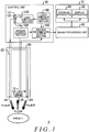
- Fig. 1 schematically shows an imaging system 5 according to a present embodiment, together with a subject.
- the imaging system 5 is used as a laparoscopic imaging system.
- the subject is a living organism such as a human body, for example.
- the imaging system 5 includes a scope section 20, a control unit 30, an image processing unit 40, and an output apparatus 70.
- the output apparatus 70 includes a display apparatus 50 and a storage apparatus 60.
- the display apparatus 50 is a display or the like for displaying a monitor image or the like of the inside of a body undergoing laparoscopic surgery.
- the storage apparatus 60 is a nonvolatile storage medium such as a hard disk, for example, and stores the images or the like of the inside of the body undergoing laparoscopic surgery.
- the output apparatus 70 may include a communication apparatus or the like that transmits the images or the like of the inside of the body undergoing laparoscopic surgery to another apparatus via an external network.
- the scope section 20 includes an imaging element 10, an objective lens 14, and a light guide 22.
- the imaging element 10 is provided near a tip portion of the scope section 20.
- the scope section 20 includes a light emission opening 24 and a light input opening 26 at the tip portion of the scope section 20.
- the light guide 22 is optically connected to the light emission opening 24.
- the light input opening 26 is provided opposite the objective lens 14, which is provided to an imaging section 12 of the imaging element 10.
- the light emitting section 130 emits lights having different characteristics from each other. These light characteristics include the wavelength region associated with the light, the modulation frequency with which the light intensity is modulated, and the like.
- the light emitting section 130 includes a light source 131, a light source 132, a light source 133, and a light source 134.
- the light source 131, the light source 132, the light source 133, and the light source 134 may be LED light sources.
- the light source 131, the light source 132, the light source 133, and the light source 134 each emit light with a different characteristic. Specifically, the light source 131 emits light associated with a red wavelength region.
- the light source 132 emits light associated with a green wavelength region.
- the light source 133 emits light associated with a blue wavelength region.
- the light source 134 emits light associated with an infrared wavelength region. Red, green, and blue are each an example of one color component in a wavelength region of visible light. Furthermore, the light associated with the red wavelength region is sometimes referred to as R light. Similarly, the light associated with the green wavelength region is sometimes referred to as G light, the light associated with the blue wavelength region is sometimes referred to as B light, and the light associated with the infrared wavelength region is sometimes referred to as IR light.
- the light emission control section 140 causes the light source 131 to emit R light that is intensity-modulated with a modulation frequency f1, by controlling the drive of the light source 131. Furthermore, the light emission control section 140 causes the light source 132 to emit G light that is intensity-modulated with a modulation frequency f2, by controlling the drive of the light source 132. The light emission control section 140 causes the light source 133 to emit B light that is intensity-modulated with a modulation frequency f3, by controlling the drive of the light source 133. The light emission control section 140 causes the light source 134 to emit IR light that is intensity-modulated with a modulation frequency f4, by controlling the drive of the light source 134.
- the light emission control section 140 emits light obtained by overlapping (superimposing) the R light, G light, B light, and IR light by controlling the drive of each light source.
- f1 100 Hz
- f2 200 Hz
- f3 400 Hz
- f4 50 Hz.
- the light emission control section 140, the light emitting section 130, and the light guide 22 function as a light emitting section that emits lights with a plurality of wavelength regions that are intensity-modulated with different modulation frequencies from each other.
- the light emission control section 140, the light emitting section 130, and the light guide 22 are one example of a light emitting section that emits lights that are intensity-modulated with different modulation frequencies from each other.
- Information indicating the values of f1, f2, f3, and f4, which are the modulation frequencies, is supplied to the imaging information output section 150 from the light emission control section 140.
- the R light from the light source 131 modulated with the modulation frequency f1, the G light from the light source 132 modulated with the modulation frequency f2, the B light from the light source 133 modulated with the modulation frequency f3, and the IR light from the light source 134 modulated with the modulation frequency f4 are superimposed on each other and supplied to the light guide 22.
- the light guide 22 is formed of optical fiber, for example. The light guide 22 guides the R light, the G light, the B light, and the IR light supplied from the light emitting section 130 to the light emission opening 24.
- the light that reaches the light emission opening 24 via the light guide 22 is emitted from the light emission opening 24 as emission light, which includes the R light, the G light, the B light, and the IR light as component lights.
- emission light which includes the R light, the G light, the B light, and the IR light as component lights.
- the R light, the G light, the B light, and the IR light from the light emitting section 130 are multiplexed and emitted from the light emission opening 24.
- the imaging element 10 is formed including a MOS image sensor.
- the imaging section 12 is formed by an imaging region in which a plurality of pixel elements of a plurality of photodiodes or the like are arranged two-dimensionally in the imaging element.
- the imaging element 10 does not include a wavelength filter that separates the light from the subject into lights with a plurality of wavelength components.
- the imaging element 10 does not include a color filter in which filters that selectively pass lights with different wavelength regions from each other and are arranged in a Bayer arrangement or the like, for example, are arranged two-dimensionally to correspond one-to-one with the plurality of pixel elements.
- each pixel element of the imaging section 12 receives the subject light from the subject, caused by the lights with the plurality of wavelength regions, at the same time.
- the wavelength region of the light that can be incident to each pixel element of the imaging section 12 is substantially the same for each pixel element.
- the imaging section 12 images the subject by receiving the subject light, which is the light from the subject. Specifically, the imaging section 12 receives the subject light that includes the light returned from the subject as a result of being irradiated with the R light, the G light, the B light, and the IR light.
- the subject light includes R light that is emitted from the light emission opening 24 and reflected or scattered by the subject, G light that is emitted from the light emission opening 24 and reflected or scattered by the subject, B light that is emitted from the light emission opening 24 and reflected or scattered by the subject, and IR light that is emitted from the light emission opening 24 and reflected or scattered by the subject.
- the imaging control section 120 controls the imaging element 10 to cause the imaging section 12 to perform imaging with a frequency that is higher than each of the modulation frequency f1, the modulation frequency f2, the modulation frequency f3, and the modulation frequency f4, thereby causing the imaging section 12 to capture a plurality of images.
- the imaging control section 120 causes the imaging section 12 to perform imaging at 800 Hz.
- the imaging control section 120 causes the imaging section 12 to image the subject, which is irradiated by the lights that have the plurality of wavelength regions and are intensity-modulated by the modulation frequencies f1, f2, f3, and f4 that are different from each other, with a higher frequency than each of these modulation frequencies.
- the imaging control section 120 may cause the imaging section 12 to perform imaging a plurality of times while changing the phase, with a frequency that is lower than at least one of the modulation frequency f1, the modulation frequency f2, the modulation frequency f3, and the modulation frequency f4.
- the imaging information output section 150 acquires image signals of the plurality of images captured at different times by the imaging element 10, and outputs the image signals acquired from the imaging element 10 as image data to the image processing unit 40.
- the imaging information output section 150 outputs the image signals acquired from the imaging element 10 to the image processing unit 40, in association with the modulation frequency information supplied from the light emission control section 140.
- the imaging information output section 150 outputs a plurality of images, which are captured by the imaging section 12, of the subject irradiated with the lights having the plurality of wavelength regions, in association with the information indicating the modulation frequencies f1, f2, f3, and f4.
- the plurality of images captured by the imaging section 12 are output to the image processing unit 40 in association with the information indicating the modulation frequencies f1, f2, f3, and f4.
- the image processing unit 40 demodulates the image signals acquired from the imaging information output section 150 based on the modulation frequency information, thereby generating various images. For example, the image processing unit 40 generates image data for display, and displays an image in the display apparatus 50 based on the generated image data. Furthermore, the image processing unit 40 generates image data for storage, and stores the generated image data in the storage apparatus 60.
- Fig. 2 is a block diagram showing the functional configuration of the image processing unit 40.
- the image processing unit 40 includes an imaging information acquiring section 280, a demodulating section 200, an image generating section 220, a change frequency specifying section 240, and a selecting section 250.
- the imaging information acquiring section 280 acquires imaging information data acquired from the imaging information output section 150.
- the imaging information data includes a plurality of images of the subject irradiated by the R light intensity-modulated with the modulation frequency f1, the G light intensity-modulated with the modulation frequency f2, the B light intensity-modulated with the modulation frequency f3, and the IR light intensity-modulated with the modulation frequency f4.
- These images are images obtained by imaging the subject, which is irradiated by the lights having the plurality of wavelength regions intensity-modulated with the modulation frequencies f1, f2, f3, and f4 that are different from each other, with a frequency higher than any of the modulation frequencies f1, f2, f3, and f4.
- red is one example of a first color component associated with the visible region.
- Green is one example of a second color component associated with the visible region.
- the blue wavelength region is one example of a third color component associated with the visible region.
- the infrared wavelength region is one example of a wavelength region outside of the visible region.
- the imaging information acquiring section 280 acquires a plurality of images of the subject irradiated with the R light intensity-modulated with the modulation frequency f1, the G light intensity-modulated with the modulation frequency f2, and the B light intensity-modulated with the modulation frequency f3.
- the demodulating section 200 demodulates the pixel values of the plurality of images for each pixel with a plurality of demodulation frequencies based on the plurality of modulation frequencies, thereby generating a plurality of pieces of pixel information indicating amounts of subject light from the subject caused by each of the lights intensity-modulated with the plurality of modulation frequencies, for each pixel.
- the pixel information generated by the demodulating section 200 has a scope that includes not only the actual values of subject light amounts for each pixel, but also values equivalent to the subject light amounts for each pixel.
- the demodulating section 200 demodulates the pixel values of the plurality of images with the plurality of demodulation frequencies based on the plurality of modulation frequencies, for each pixel, thereby generating a plurality of pieces of pixel information indicating the amounts of subject light from the subject caused by each of the lights having the plurality of wavelength regions, for each pixel.
- the demodulating section 200 demodulates the pixel values of the plurality of images with a demodulation frequency based on the modulation frequency f1, for each pixel, thereby generating a plurality of pieces of pixel information indicating the amounts of subject light from the subject caused by the R light, for each pixel.
- the demodulating section 200 demodulates the pixel values of the plurality of images with a demodulation frequency based on the modulation frequency f2, for each pixel, thereby generating a plurality of pieces of pixel information indicating the amounts of subject light from the subject caused by the G light, for each pixel.
- the demodulating section 200 demodulates the pixel values of the plurality of images with a demodulation frequency based on the modulation frequency f3, for each pixel, thereby generating a plurality of pieces of pixel information indicating the amounts of subject light from the subject caused by the B light, for each pixel.
- the demodulating section 200 demodulates the pixel values of the plurality of images with a demodulation frequency based on the modulation frequency f4, for each pixel, thereby generating a plurality of pieces of pixel information indicating the amounts of subject light from the subject caused by the IR light, for each pixel.
- the demodulating section 200 demodulates the pixel values of the plurality of images with the modulation frequency f1, the modulation frequency f2, the modulation frequency f3, and the modulation frequency f4 for each pixel.
- the demodulation frequencies match the modulation frequencies. In this way, the demodulating section 200 demodulates the pixel values of the plurality of images with the plurality of modulation frequencies, for each pixel.
- the demodulating section 200 demodulates the pixel values of the plurality of images for each pixel with the modulation frequency f1, thereby generating the red pixel information for each pixel. Furthermore, the demodulating section 200 demodulates the pixel values of the plurality of images for each pixel with the modulation frequency f2, thereby generating the green pixel information for each pixel. The demodulating section 200 demodulates the pixel values of the plurality of images for each pixel with the modulation frequency f3, thereby generating the blue pixel information for each pixel. The demodulating section 200 demodulates the pixel values of the plurality of images for each pixel with the modulation frequency f4, thereby generating the infrared pixel information for each pixel.
- the demodulating section 200 demodulates the pixel values of the plurality of images for each pixel with the plurality of modulation frequencies, thereby generating the plurality of pieces of pixel information for each pixel. It should be noted that, before performing the demodulation described above, the demodulating section 200 may perform pre-processing (a correction process) such as noise removal to compare each pixel to nearby pixels and remove noise. Furthermore, a correcting section may be provided between the imaging information acquiring section 280 and the demodulating section 200, and this correcting section may perform the pre-processing.
- pre-processing a correction process
- a correcting section may be provided between the imaging information acquiring section 280 and the demodulating section 200, and this correcting section may perform the pre-processing.
- the image generating section 220 generates images caused by light from the subject resulting from each of the lights intensity-modulated with the plurality of modulation frequencies, based on the plurality of pieces of pixel information for each pixel generated by the demodulating section 200.
- the image generating section 220 generates the images caused by the light from the subject resulting from each of the lights having the plurality of wavelength regions, based on the plurality of pieces of pixel information for each pixel generated by the demodulating section 200.
- the image generating section 220 may generate a visible light image based on the red pixel information, the green pixel information, and the blue pixel information.
- the image generating section 220 may generate an infrared light image based on the infrared pixel information.
- the image generating section 220 may generate an image obtained by superimposing the infrared light image on the visible light image.
- the images generated by the image generating section 220 are output to the output apparatus 70.
- the image generating section 220 may separate the red pixel information, the green pixel information, the blue pixel information, and the infrared pixel information from the pixel information of each pixel element obtained when the imaging section 12 performed imaging, thereby generating the image resulting from background light that is not light from the light source 133.
- the image generating section 220 may subtract the total value of the red pixel information, the green pixel information, the blue pixel information, and the infrared pixel information corresponding to each pixel element from the value obtained by performing time integration of the pixel information of each pixel element of the imaging section 12 according to a time based on the respective modulation frequencies, thereby generating the pixel information of the image caused by background light.
- the time used for the time integration may be a period corresponding to the lowest frequency among the modulation frequencies f1, f2, f3, and f4.
- the change frequency specifying section 240 performs a frequency analysis on the pixel information obtained by the demodulating section 200 performing demodulation with at least one modulation frequency among the plurality of modulation frequencies, thereby specifying the frequency fv of the change over time of the subject.
- the change over time of the subject is movement of the subject.
- the movement of the subject is a change over time of the position of the entire subject or a portion of the subject.
- the demodulating section 200 further demodulates the pixel values of the plurality of images with a frequency that is the sum of the modulation frequency f1 and the frequency fv, thereby generating pixel information representing the change over time of the subject.
- the demodulating section 200 further demodulates the pixel values of the plurality of images with a frequency that is the sum of the modulation frequency f2 and the frequency fv, thereby generating pixel information representing the change over time of the subject.
- the demodulating section 200 further demodulates the pixel values of the plurality of images with a frequency that is the sum of the modulation frequency f3 and the frequency fv, thereby generating pixel information representing the change over time of the subject.
- the demodulating section 200 further demodulates the pixel values of the plurality of images with a frequency that is the sum of the modulation frequency f4 and the frequency fv, thereby generating pixel information representing the change over time of the subject.
- the demodulating section 200 demodulates the pixel values of the plurality of images with frequencies that are each the sum of at least one modulation frequency among the plurality of modulation frequencies and the frequency of the change over time of the subject specified by the change frequency specifying section 240, thereby generating the pixel information representing the change over time of the subject. It should be noted that the demodulating section 200 may demodulate the pixel values of the plurality of images with frequencies that are each the difference between at least one modulation frequency among the plurality of modulation frequencies and the frequency of the change over time of the subject specified by the change frequency specifying section 240, thereby generating the pixel information representing the change over time of the subject.
- the demodulating section 200 may demodulate the pixel values of the plurality of images with frequencies that are each at least one of the difference between and the sum of at least one modulation frequency among the plurality of modulation frequencies and the frequency of the change over time of the subject specified by the change frequency specifying section 240, thereby generating the pixel information representing the change over time of the subject.
- the demodulating section 200 may demodulate the pixel values of the plurality of images with frequencies that are each at least one of the sum of and the difference between at least one modulation frequency among the plurality of modulation frequencies and the frequency of the change over time of a plurality of groups each formed from a plurality of pixels, thereby generating a plurality of pieces of pixel information representing the change over time of the subject.
- the change frequency specifying section 240 may perform a frequency analysis on the pixel information obtained by the demodulating section 200 performing demodulation with at least one modulation frequency among the plurality of modulation frequencies, for each of the plurality of groups formed from the plurality of pixels, thereby specifying the frequency fv of the change over time of the subject.
- the demodulating section 200 may perform demodulation with a frequency that is at least one of the sum of and the difference between at least one modulation frequency among the plurality of modulation frequencies and the frequency fv specified for each of the plurality of groups of pixels by the change frequency specifying section 240, thereby generating the pixel information representing the change over time of the subject for each of the plurality of groups of the pixels.
- a group formed from a plurality of pixels indicates a region showing the subject or a portion of the subject within the image, and a plurality of the groups indicates that there are a plurality of such regions existing in the images.
- the image generating section 220 may generate a change image that represents the change of the subject, based on the pixel information representing the change over time of the subject.
- the image generating section 220 may generate the image obtained by superimposing the change image on the visible light image described above.
- the image including the information of the change image generated by the image generating section 220 is output to the output apparatus 70.
- the demodulating section 200 may perform demodulation with a frequency that is the sum of at least one modulation frequency among the plurality of modulation frequencies and the specified change frequency, without performing a frequency analysis on the image that has been demodulated with the modulation frequency. In this way, the demodulating section 200 generates the pixel signals representing the change over time of the subject by demodulating the pixel signals of the plurality of images with a frequency that is the sum of at least one modulation frequency among the plurality of modulation frequencies and a predetermined change frequency representing the frequency of the change over time of the subject.
- demodulating section 200 may generate the pixel signals representing the change over time of the subject by demodulating the pixel signals of the plurality of images with a frequency that is the difference between at least one modulation frequency among the plurality of modulation frequencies and a predetermined change frequency representing the frequency of the change over time of the subject. In this way, the demodulating section 200 may generate the pixel signals representing the change over time of the subject by demodulating the pixel signals of the plurality of images with a frequency that is at least one of the sum of and the difference between at least one modulation frequency among the plurality of modulation frequencies and a predetermined change frequency representing the frequency of the change over time of the subject.
- a type of change for which the change frequency can be identified without performing a frequency analysis can be exemplified by a change in the subject caused by the effect of the heart rate, a change in the subject caused by the effect of peristaltic motion of organs, or the like.
- the change frequency of the subject may be detected based on the output of a sensor, such as a heart rate sensor, attached to the living organism serving as the subject.
- the change frequency of the subject is one example of a target frequency, which is a frequency to be extracted from the images.
- the plurality of demodulation frequencies used by the demodulating section 200 for the demodulation may match the plurality of modulation frequencies.
- the plurality of demodulation frequencies may be at least one of the sum of and the difference between the plurality of modulation frequencies and the target frequency, such as the change frequency of the subject.
- the plurality of demodulation frequencies used by the demodulating section 200 for the demodulation are frequencies based on at least the modulation frequencies.
- the demodulating section 200 by demodulating the pixel values of the plurality of images for each pixel with the plurality of demodulation frequencies based on the plurality of modulation frequencies, the demodulating section 200 generates the plurality of pieces of pixel information indicating the amounts of subject light from the subject caused by light having each of the plurality of wavelength regions, for each pixel.
- the imaging information acquiring section 280 may acquire information indicating phase differences between the phase of the intensity change of at least one light among the lights having the plurality of wavelength regions and the phase at which each of the plurality of images is captured.
- the demodulating section 200 may then adjust the phase differences between each phase at which the plurality of images are captured and a phase of a reference signal used for demodulation to be a predetermined phase, based on the phase difference indicated by the information acquired by the imaging information acquiring section 280, and perform demodulation with the plurality of modulation frequencies for each pixel.
- the demodulating section 200 may cause the phase differences between each phase at which the plurality of images are captured and the phase of the reference signal used for demodulation to substantially match the phase differences between the phase of the intensity change of the light and each phase at which the plurality of images are captured, and perform demodulation with the plurality of modulation frequencies for each pixel.
- the selecting section 250 may select one demodulation frequency from among the plurality of demodulation frequencies to be used in the demodulation by the demodulating section 200.
- the demodulating section 200 may perform demodulation with the demodulation frequency selected by the selecting section 250.
- the selecting section 250 may select the demodulation frequency that is n times (n is an integer) the frequency of the time change of the background light, from among the plurality of demodulation frequencies.
- the selecting section 250 may select the demodulation frequency that is 2" times (n is an integer) the frequency of the time change of the background light, from among the plurality of demodulation frequencies.
- the modulation frequency is a rectangular wave, a harmonic wave is included in the signal, and therefore the separation capability is good when the base frequency of each modulation signal uses the 2 n -times relationship.
- the modulation frequency is a single frequency signal (e.g. a sine wave), sufficient separation is possible with the n-times relationship, without using the 2 n -times relationship.
- the selecting section 250 may select the demodulation frequency that is n times or 2 n times (n is an integer) the frequency of the time change of the background light.
- the frequency of the time change of the background light may be input from the outside.
- the selecting section 250 may select the demodulation frequency having the greatest distance relative to the frequency of the time change of the background light, from among the plurality of demodulation frequencies. In a case where the frequency of the time change of the background light changes over time, the frequency of the time change of the background light differs according to the location, or the like, the selecting section 250 may select the demodulation frequency that has the greatest difference relative to the frequency of the time change of the background light. As an example, the selecting section 250 may select a specified modulation frequency based on instructions from a user. For example, if instructions for displaying an image with IR light are received from the user, the selecting section 250 selects the modulation frequency f4 based on the instructions from the user.
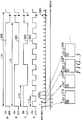
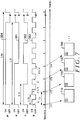
- Fig. 3 shows examples of a light emission control sequence and an imaging sequence.
- the sequence 381 indicates the light emission state of the light source 131.
- the sequence 382 indicates the light emission state of the light source 132.
- the sequence 383 indicates the light emission state of the light source 133.
- the sequence 384 indicates the light emission state of the light source 134.
- ON indicates a state where light is being emitted
- OFF indicates a state where light is not being emitted.
- the sequence 390 indicates the imaging sequence of the imaging section 12.
- Each timing 392 shown in the sequence 390 indicates a timing at which an image is captured.
- the timings 392 indicate the timings of a vertical synchronization signal.
- the imaging section 12 captures the images with an imaging interval T, under the control of the imaging control section 120.
- the imaging interval T is represented by the time between timings 392 that are temporally adjacent.
- the imaging interval T of the imaging section 12 is shorter than a modulation period 1/f3 corresponding to the modulation frequency f3.
- the imaging interval T is shorter than the half-period of the modulation period 1/f3.
- the imaging interval T may be shorter than the 1/3-period of the modulation period 1/f3.
- the imaging interval T may be shorter than the 1/4-period of the modulation period 1/f3.
- the pixel value of one pixel 301 among the plurality of pixels of the image 310 obtained at the timing t1 can have a value corresponding to the total light amount of the R light returning from the subject as a result of the R light incident to the subject being reflected, scattered, or the like by the subject; the G light returning from the subject as a result of the G light incident to the subject being reflected, scattered, or the like by the subject; the B light returning from the subject as a result of the B light incident to the subject being reflected, scattered, or the like by the subject; and the IR light returning from the subject as a result of the IR light incident to the subject being reflected, scattered, or the like by the subject.
- the image 320 obtained at the timing t2 and the image 340 obtained at the timing t4 are similar to the image 310.
- the pixel value of one pixel 301 among the plurality of pixels of the image 330 obtained at the timing t3 can have a value corresponding to the total light amount of the R light returning from the subject as a result of the R light incident to the subject being reflected, scattered, or the like by the subject; the G light returning from the subject as a result of the G light incident to the subject being reflected, scattered, or the like by the subject; and the IR light returning from the subject as a result of the IR light incident to the subject being reflected, scattered, or the like by the subject.
- each pixel value of each image can have a value corresponding to the total amount of light from the subject caused by each of the lights having the plurality of wavelength regions among the emitted lights. If there is background light that is not light from the light source 133, each pixel value of each image can have a value corresponding to the amount of light from the subject caused by the background light. In other words, each pixel value of each image can have a value corresponding to the sum of the total amount of light from the subject caused by each of the lights having the plurality of wavelength regions from the light source 133 and the amount of light from the subject caused by the background light.
- the imaging control section 120 may cause the imaging section 12 to capture each of the plurality of images in accordance with a predetermined phase relative to the intensity change of the lights having the plurality of wavelength regions. For example, if the timing of the rising of the light emission intensity of the B light is used as a reference timing, the imaging control section 120 may perform imaging in synchronization with the reference timing. In this case, the imaging control section 120 may set the imaging period T to be 1/(integer value) of 1/f3. In this way, by causing the imaging section 12 to perform imaging in accordance with a phase relative to the intensity change of the emission light, there are cases where the imaging phase difference is taken into consideration and the reference waveform does not need to be adjusted when the demodulating section 200 performs demodulation.
- the imaging control section 120 outputs information indicating the imaging order and imaging timing of each image, to the imaging information output section 150.
- the light emission control section 140 outputs information indicating the light emission timing of each light source of the light emitting section 130 to the imaging information output section 150.
- the light emission control section 140 outputs information indicating the timing at which the light emitting section 130 starts the modulation of the emission light intensity of each light source, to the imaging information output section 150.
- the light emission control section 140 outputs information indicating the emission light intensity of each light source of the light emitting section 130 to the imaging information output section 150.
- the imaging information output section 150 outputs to the image processing unit 40, in association with the images, these pieces of information acquired from the light emission control section 140 and the imaging control section 120. In this way, in the image processing unit 40, the demodulating section 200 can perform accurate demodulation using the information associated with the images. Furthermore, the image generating section 220 can generate images with suitable luminance, based on the emission light intensity and the like of each light source.
- modulation frequencies of the B light, the G light, the R light, and the IR light are highest to lowest in the stated order.
- the modulation frequencies may be suitably determined according to the observation target. For example, if there is a desire to acquire a red image with higher time resolution, the modulation frequency of the R light may be made higher than the modulation frequencies of the other lights.
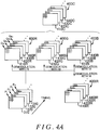
- Fig. 4A schematically shows image processing of the image processing unit 40.
- the demodulating section 200 generates a plurality of images including an image 410R, an image 420R, an image 430R, an image 440R, etc. by demodulating a plurality of images including an image 310, an image 320, an image 330, and an image 340, etc. with the demodulation frequency f1 for each pixel.
- the demodulating section 200 generates discrete time series data including a pixel value QR1 of the pixel 301 of the image 410R, a pixel value QR2 of the pixel 301 of the image 420R, a pixel value QR3 of the pixel 301 of the image 430R, a pixel value QR4 of the pixel 301 of the image 440R, etc.
- the demodulating section 200 generates the pixel value of each pixel of the image 410R, the image 420R, the image 430R, the image 440R, etc. by applying a similar process to these other pixels.
- the demodulating section 200 generates a plurality of images including an image 410G, an image 420G, an image 430G, an image 440G, etc. by demodulating a plurality of images include an image 310, an image 320, an image 330, and an image 340, etc. with the demodulation frequency f2 for each pixel.
- the demodulating section 200 generates a plurality of images including an image 410B, an image 420B, an image 430B, an image 440B, etc. by demodulating a plurality of images include an image 310, an image 320, an image 330, and an image 340, etc. with the demodulation frequency f3 for each pixel.
- the demodulating section 200 generates a plurality of images including an image 410IR, an image 420IR, an image 430IR, an image 440IR, etc. by demodulating a plurality of images include an image 310, an image 320, an image 330, and an image 340, etc. with the demodulation frequency f4 for each pixel.
- the processing performed by the demodulating section 200 to generate these images is the same as the processing for generating the image 410R, the image 420R, the image 430R, and the image 440R, except that the processing based on the demodulation frequency is different. Therefore, a description of the details of the processing for generating these images is omitted.
- the image generating section 220 generates a visible light image group 400C, which is an image group forming a colorized visible light moving image, from the image group 400R, the image group 400G, and the image group 400B. Specifically, the image generating section 220 generates an image 410C containing each color component, from the image 410R, the image 410G, and the image 410B. Similarly, the image generating section 220 generates an image 420C containing each color component, from the image 420R, the image 420G, and the image 420B. Similarly, the image generating section 220 generates an image 430C containing each color component, from the image 430R, the image 430G, and the image 430B.
- the image generating section 220 generates an image 440C containing each color component, from the image 440R, the image 440G, and the image 440B.
- the image 410C, the image 420C, the image 430C, and the image 440C may be images that form a colorized visible light moving image.
- the image generating section 220 may generate image data of the visible light image group 400C expressed as a luminance signal and a color differential signal for processing at later stages. For example, when generating video signal information for display, the image generating section 220 generates YUV component signal information. When generating image data for storage, the image generating section 220 generates YCrCb image data from the visible light image group 400, and performs a moving image compression process. Furthermore, the image generating section 220 generates images included in the image group 400IR, as images forming a moving image resulting from infrared light.
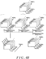
- Fig. 4B schematically shows image processing relating to the change frequency specifying section 240.
- the change frequency specifying section 240 specifies the change frequency fv representing the movement or the like of the subject, by performing a frequency analysis on the pixel values of the image 410R, the image 420R, the image 430R, the image 440R, etc., for example.
- the change frequency specifying section 240 separates the frequency components of the time series signal formed by the pixel values of a specified pixel in the image 410R, the image 420R, the image 430R, the image 440R, etc., and determines the frequency of the frequency component amount exceeding a predetermined threshold value to be the change frequency fv.
- the demodulating section 200 generates a plurality of images including an image 410Rv, an image 420Rv, an image 430Rv, an image 440Rv, etc. by demodulating the plurality of images including the image 310, the image 320, the image 330, the image 340, etc. with the modulation frequency f1+fv for each pixel. Furthermore, the demodulating section 200 generates a plurality of images including an image 410Gv, an image 420Gv, an image 430Gv, an image 440Gv, etc. by demodulating the plurality of images including the image 310, the image 320, the image 330, the image 340, etc. with the modulation frequency f2+fv for each pixel.
- the demodulating section 200 generates a plurality of images including an image 410Bv, an image 420Bv, an image 430Bv, an image 440Bv, etc. by demodulating the plurality of images including the image 310, the image 320, the image 330, the image 340, etc. with the modulation frequency f3+fv for each pixel.
- the demodulating section 200 generates a plurality of images including an image 410IRv, an image 420IRv, an image 430IRv, an image 440IRv, etc. by demodulating the plurality of images including the image 310, the image 320, the image 330, the image 340, etc. with the modulation frequency f4+fv for each pixel.
- the processing performed by the demodulating section 200 to generate these images is the same as the processing for generating the image 410R, the image 420R, the image 430R, and the image 440R, except that the processing based on the demodulation frequency is different. Therefore, a description of the details of the processing for generating these images is omitted.
- the image generating section 220 generates a visible light image group 400Cv, which is an image group forming a colorized visible light moving image representing the movement of the subject, from the image group 400Rv the image group 400Gv, and the image group 400Bv. Specifically, the image generating section 220 generates an image 410Cc containing each color component, from the image 410Rv, the image 410Gv, and the image 410Bv. Similarly, the image generating section 220 generates an image 420Cv containing each color component, from the image 420Rv, the image 420Gv, and the image 420Bv.
- the image generating section 220 generates an image 430Cv containing each color component, from the image 430Rv, the image 430Gv, and the image 430Bv.
- the image generating section 220 generates an image 440Cv containing each color component, from the image 440Rv, the image 440Gv, and the image 440Bv.
- the image 410Cv, the image 420Cv, the image 430Cv, and the image 440Cv may be frame images that form a colorized visible light moving image representing movement of the subject.
- the image generating section 220 generates images included in the image group 400IRv, as images forming a moving image resulting from infrared light.
- the change frequency specifying section 240 may specify the change frequency fv by performing a frequency analysis on the pixel values for each of the plurality of pixels of the image 410R, the image 420R, the image 430R, the image 440R, etc. Furthermore, the change frequency specifying section 240 may perform the pixel value frequency analysis for each pixel. In addition, the change frequency specifying section 240 may specify the change frequency fv by performing a frequency analysis on a time series signal formed by the average values of a predetermined plurality of pixels.
- f1+fv is used as the demodulation frequency used for the demodulation process for generating the image group 400Rv.
- f1-fv may instead be used as the demodulation frequency used for the demodulation process for generating the image group 400Rv.
- f2-fv may instead be used as the demodulation frequency used for the demodulation process for generating the image group 400Gv.
- f3-fv may instead be used as the demodulation frequency used for the demodulation process for generating the image group 400Bv.
- f4-fv may instead be used as the demodulation frequency used for the demodulation process for generating the image group 400IRv.
- FIG. 4B shows the process performed when one change frequency fv is specified. If a plurality of change frequencies are specified, images may be generated for each change frequency by performing demodulation with the modulation frequencies and the demodulation frequencies based on the modulation frequencies, for each of the plurality of change frequencies.
- Fig. 5 schematically shows processing of a pixel unit by the demodulating section 200.
- the demodulating section 200 performs multiplication 510 between the time series data formed by P1, P2, P3, P4, etc. and the time series data of the reference waveform of the change frequency f1.
- the demodulating section 200 then applies a frequency filter 512 to the time series data obtained as a result of the multiplication 510, thereby generating the time series data QR1, QR2, QR3, QR4, etc. of the red pixel value.
- the frequency filter 512 preferably includes a frequency characteristic that substantially cuts off the frequency component of the frequency that is the difference between the modulation frequency f1 and another modulation frequency and the frequency component of the frequency that is the sum of the modulation frequency f1 and another modulation frequency.
- the frequency filter 512 may be a low-pass filter.
- the demodulating section 200 performs multiplication 520 between the time series data Pk and the time series data of the reference waveform of the change frequency f2.
- the demodulating section 200 then applies a frequency filter 522 to the time series data obtained as a result of the multiplication 520, thereby generating the time series data QG1, QG2, QG3, QG4, etc. of the green pixel value.
- the frequency filter 522 preferably includes a frequency characteristic that substantially cuts off the frequency component of the frequency that is the difference between the modulation frequency f2 and another modulation frequency and the frequency component of the frequency that is the sum of the modulation frequency f2 and another modulation frequency.
- the frequency filter 522 may be a low-pass filter.
- the demodulating section 200 performs multiplication 530 between the time series data Pk and the time series data of the reference waveform of the change frequency f3.
- the demodulating section 200 then applies a frequency filter 532 to the time series data obtained as a result of the multiplication 530, thereby generating the time series data QB1, QB2, QB3, QB4, etc. of the blue pixel value.
- the frequency filter 532 preferably includes a frequency characteristic that substantially cuts off the frequency component of the frequency that is the difference between the modulation frequency f3 and another modulation frequency and the frequency component of the frequency that is the sum of the modulation frequency f3 and another modulation frequency.
- the frequency filter 532 may be a low-pass filter.
- the demodulating section 200 performs multiplication 540 between the time series data Pk and the time series data of the reference waveform of the change frequency f4.
- the demodulating section 200 then applies a frequency filter 542 to the time series data obtained as a result of the multiplication 540, thereby generating the time series data QIR1, QIR2, QIR3, QIR4, etc. of the infrared pixel value.
- the frequency filter 542 preferably includes a frequency characteristic that substantially cuts off the frequency component of the frequency that is the difference between the modulation frequency f4 and another modulation frequency and the frequency component of the frequency that is the sum of the modulation frequency f4 and another modulation frequency.
- the frequency filter 542 may be a low-pass filter.
- the demodulating section 200 preferably uses time series data with a phase substantially the same as the phase of the intensity change of the R light, as the time series data of the change frequency f1 used in the multiplication 510.
- the difference between the rising timing of the intensity change of the R light and the imaging timing t1 is preferably caused to substantially match the difference between the rising timing of the reference waveform indicated by the time series data used in the multiplication 510 and the timing at which the image 410 is captured in this reference waveform.
- the phase of the reference signal in the demodulation process is preferably caused to match the phase of the modulation signal.
- the demodulating section 200 preferably uses time series data with a phase substantially the same as the phase of the intensity change of the G light, as the time series data of the change frequency f2 used in the multiplication 520.
- the demodulating section 200 preferably uses time series data with a phase substantially the same as the phase of the intensity change of the B light, as the time series data of the change frequency f3 used in the multiplication 530.
- the demodulating section 200 preferably uses time series data with a phase substantially the same as the phase of the intensity change of the IR light, as the time series data of the change frequency f4 used in the multiplication 540.
- Fig. 5 is used to describe processing of the demodulating section 200 for the time series data Pk of the pixel values for the pixel 301 at a specified position in the image.
- the demodulating section 200 can acquire the time series data of the pixel values corresponding to each wavelength region at the arbitrary position (i, j).
- Fig 5 is used to describe a case in which the demodulating section 200 applies the modulation frequencies as the demodulation frequencies.
- the demodulating section 200 When generating an image in which the red pixel values represent change of the subject, for the time series data Pk, the demodulating section 200 only needs to apply f1+fv as the demodulation frequency and apply similar multiplication and a similar frequency filter.
- the demodulating section 200 when generating an image in which the green pixel values represent change of the subject, for the time series data Pk, the demodulating section 200 only needs to apply f2+fv as the demodulation frequency and apply similar multiplication and a similar frequency filter.
- the demodulating section 200 When generating an image in which the blue pixel values represent change of the subject, for the time series data Pk, the demodulating section 200 only needs to apply f3+fv as the demodulation frequency and apply similar multiplication and a similar frequency filter. When generating an image in which the infrared pixel values represent change of the subject, for the time series data Pk, the demodulating section 200 only needs to apply f4+fv as the demodulation frequency and apply similar multiplication and a similar frequency filter.
- the imaging system 5 it is possible to acquire images caused by lights having a plurality of wavelength regions, by multiplexing lights that are intensity-modulated with modulation frequencies differing for each wavelength and irradiating the subject. Therefore, it is possible to acquire images based on lights having the plurality of wavelength regions, without radiating the irradiation light with time separation for each wavelength region and without performing imaging with the light of each wavelength region with time separation. Furthermore, there is no need to perform wavelength separation for each pixel with a color filter or the like in the imaging element. Therefore, it is possible to perform imaging of the subject with high resolution. In this way, it is possible to miniaturize the imaging apparatus.
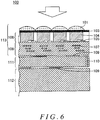
- Fig. 6 is a cross-sectional view of an imaging element 100 that is a modification of the imaging element 10.
- the imaging element 100 is a backside illumination imaging element.
- the imaging element 100 includes an imaging chip 113 that outputs a pixel signal corresponding to the incident light, a signal processing chip 111 that processes the pixel signal, and a memory chip 112 that stores the pixel signal.
- the imaging chip 113, the signal processing chip 111, and the memory chip 112 are layered, and are electrically connected to each other by bumps 109 that are conductive and made of Cu or the like.
- the incident light is mainly incident in the direction indicated by the white arrow.
- the surface of the imaging chip 113 to which the incident light is incident is referred to as the back surface.
- the imaging chip 113 is a backside illumination MOS image sensor, for example.
- the photodiode layer 106 is arranged on the back surface side of the wiring layer 108.
- the photodiode layer 106 includes a plurality of photodiodes 104 arranged two-dimensionally and transistors 105 provided corresponding to the photodiodes 104.
- a set of a photodiode 104 and a transistor 105 forms one pixel element.
- Microlenses 101 are provided on the side of the photodiode layer 106 to which the incident light is incident, with a passivation film 103 interposed therebetween.
- the microlenses 101 are provided to correspond respectively to the pixels.
- Each microlens 101 focuses the incident light toward the corresponding photodiode 104.
- the wiring layer 108 includes wiring 107 that transmits the pixel signals from the photodiode layer 106 to the signal processing chip 111.
- the wiring 107 may be multilayered, and passive elements and active elements may be provided.
- a plurality of the bumps 109 are provided on the wiring layer 108. These bumps 109 are aligned with a plurality of bumps 109 provided on the surface of the signal processing chip 111 opposite thereto, and the aligned bumps 109 are bonded to each other as a result of pressure or the like being applied to the imaging chip 113 and the signal processing chip 111 to form an electrical connection.
- a plurality of bumps 109 are formed on the surfaces of the signal processing chip 111 and the memory chip 112 that face each other. These bumps 109 are aligned with each other, and the aligned bumps 109 are bonded to each other as a result of pressure or the like being applied to the signal processing chip 111 and the memory chip 112 to form an electrical connection.
- the bonding between the bumps 109 is not limited to Cu bump bonding caused by solid phase diffusion, and may instead be micro bump bonding caused by solder fusion. In this way, the imaging chip 113 and the signal processing chip 111 that includes the processing circuits are electrically connected with a layered structure.
- the signal processing chip 111 includes a silicon penetration electrode 110 that connects the circuits provided on the front and back surfaces thereof to each other.
- the silicon penetration electrode 110 is preferably provided in a peripheral region.
- the silicon penetration electrode 110 may be provided in the peripheral region of the imaging chip 113 or in the memory chip 112.
- the signal processing chip 111 includes a signal processing circuit that processes the pixel signals from the photodiode layer 106.
- the signal processing chip 111 includes a signal processing circuit that performs column amplification, correlated double sampling (CDS), and analog/digital (A/D) conversion.
- the pixel signals from the photodiode 104 undergo amplification, CDS, and A/D conversion by the signal processing circuit of the signal processing chip 111.
- the imaging element 100 it is possible to provide the signal processing chip 111 with a column amplifier, a CDS circuit, and an AD conversion circuit.
- the memory chip 112 includes a pixel memory corresponding to each pixel.
- the pixel signals that have been A/D converted by the signal processing chip 111 are stored in the pixel memory of the memory chip 112.
- the signal processing chip 111 includes a computational circuit that processes the pixel signals stored in the pixel memory.
- the computational circuit of the signal processing chip 111 may have a function to perform at least a portion of the processing of the image processing unit 40.
- the computational circuit of the signal processing chip 111 may have a function to perform at least a portion of the process of the imaging information acquiring section 280, the demodulating section 200, the change frequency specifying section 240, the selecting section 250, and the image generating section 220. In this way, the computational circuit of the signal processing chip 111 may perform at least a portion of the process for performing the frequency separation based on the modulation frequencies for multiplexing the emitted light.
- the computational circuit of the signal processing chip 111 may perform data compression on the pixel signals, and output the result. In this way, it is possible to reduce the load of the input/output interface of the pixel signals. It should be noted that the computational circuit may be provided in the memory chip 112.
- the imaging element 100, the imaging chip 113, the signal processing chip 111 including the processing circuit and the memory chip 112 are layered three-dimensionally with a layered structured. Therefore, it is possible to hold the pixel signals and perform signal processing on the pixel signals in the signal processing chip 111 and the memory chip 112 near the imaging chip 113. In this way, it is possible to increase the speed of reading the pixels and to reduce the amount of data output from the imaging element 100. Furthermore, it is possible to reduce the load at later stages of the imaging element 100. Accordingly, it is possible to shorten the imaging period for the images.
- the subject is imaged using R light, G light, B light, and IR light.
- the light used for imaging is not limited to a combination of R light, G light, B light, and IR light.
- Lights with combinations of various wavelength regions can be adopted as the light used for imaging. It should be noted that a portion of the wavelength region of a certain light used for the imaging may overlap with the wavelength region of another light.
- the wavelength region of a certain light used for the imaging may be a partial wavelength region of the wavelength region of another light. In this way, the subject may be irradiated by lights with partially overlapping wavelength regions that have been intensity-modulated with a plurality of modulation frequencies.
- the wavelength region of a certain light used for the imaging may overlap with the entire range of the wavelength region of another light.
- IR lights having the same wavelength regions may be modulated with different modulation frequencies from each other and used to irradiate the subject.
- the subject may be irradiated with, in addition to first IR light that is intensity-modulated with the modulation frequency f4, second IR light that has the same wavelength region as the first IR light and is intensity-modulated with a modulation frequency f5 that is different from the modulation frequency f4.
- white lights may be modulated with different modulation frequencies from each other and used to irradiate the subject.
- the subject may be irradiated with lights that are intensity-modulated with a plurality of modulation frequencies and that have wavelength regions that entirely overlap.
- Lights that have identical wavelength regions but are intensity-modulated with different modulation frequencies are one example of lights that have different characteristics from each other.
- redundancy is realized with regard to the wavelength regions of the lights irradiating the subject and the subject may be irradiated with lights that have the same wavelength and are intensity-modulated with modulation frequencies that are different from each other.
- the subject may be irradiated with lights that have matching wavelength regions and are intensity-modulated with a plurality of modulation frequencies.
- “matching wavelength regions” includes not only wavelength regions whose upper limit values and lower limit values are matching, but also whose upper limit values and lower limit values are substantially matching.
- “Substantially matching” has a scope including an error caused by variation between apparatuses.
- “matching wavelength regions” has a scope that includes lights without a range limit on the wavelength region, such as white lights, having overlapping wavelength region.
- lights with “matching wavelength regions” may have optical spectra in the wavelength region that are all matching or that are different. In the wavelength region, the peak wavelengths of the irradiation intensity may be the same or may be different.
- light from a single light source may be intensity-modulated by the sum of the modulations signals with a plurality of modulation frequencies, or lights from a plurality of light sources that emit lights with matching wavelength regions may be intensity-modulated with different modulation frequencies.
- the light emission control section 140 drives a single light source 134 according to a modulation intensity obtained by combining the modulation frequency f4 and the modulation frequency f5, thereby causing the light source 134 to generate IR light obtained by multiplexing the IR light intensity-modulated with the modulation frequency f4 and the IR light intensity-modulated with the modulation frequency f5 from the light source 134.
- a separate light source may be added to generate the IR light intensity-modulated with the modulation frequency f5.
- the selecting section 250 selects whether to generate the pixel information indicating the subject light amount from the subject caused by the light intensity-modulated with the modulation frequency f4 or to generate the pixel information indicating the subject light amount from the subject caused by the light intensity-modulated with the modulation frequency f5. For example, from among the modulation frequency f4 and the modulation frequency f5, the selecting section 250 selects the frequency whose difference relative to the optical disturbance frequency is greater than a predetermined value as the demodulation frequency. Specifically, from among the modulation frequency f4 and the modulation frequency f5, the selecting section 250 selects the modulation frequency whose difference relative to the frequency of the time change of the background light is greater as the demodulation frequency.
- the selecting section 250 selects f5 as the demodulation frequency.
- the demodulating section 200 performs demodulation with f5.
- the image generating section 220 then generates the image caused by the light from the subject resulting from the RI light intensity-modulated with the modulation frequency f5, based on the pixel information of each pixel generated by the demodulation performed by the demodulating section 200 with f5.
- the frequency of the time change of the background light may be specified based on the pixel information of the image of the background light generated by the image generating section 220.
- the frequency of the time change of the background light may be input from outside of the imaging system 5, and may be designated by the user.
- the effect of the background light is included in the pixel information acquired by performing demodulation with a demodulation frequency that matches this modulation frequency. Therefore, there are cases where the S/N ratio of the pixel information resulting from the IR light is undesirably low.
- the selecting section 250 select a frequency that is distanced from the frequency of the time change of the background light, it is possible to generate an image using pixel information with a higher S/N ratio. By having a redundancy for the wavelength of the light irradiating the subject, it is possible to increase the tolerance with respect to optical disturbance.
- the selecting section 250 may select, from among the three or more modulation frequencies, the frequency whose difference with respect to the frequency of the time change of the background light is greatest as the demodulation frequency.
- Fig. 7 shows a modification of the imaging sequence along with the light emission control sequence.
- Fig. 7 shows an imaging sequence for effectively generating the pixel information by having the demodulating section 200 perform demodulation with the modulation frequency f3 while making the imaging interval longer than the period 1/f3 corresponding to the modulation frequency f3.
- Fig. 7 shows an imaging sequence in a case where the imaging interval T7 is set to 1/f3+1/(4 ⁇ f3).
- the demodulating section 200 performs demodulation with the demodulation frequency f3 while treating the image 710, the image 720, the image 730, and the image 740 captured at the timing t71, the timing t72, the timing t73, and the timing t74 respectively as images captured at the phase 0, the phase 2 ⁇ /4, the phase ⁇ , and the phase 6 ⁇ /4 in one period. In this way, it is possible to effectively generate the pixel information of the B image by performing demodulation with the modulation frequency f3 while making the imaging interval longer than the period 1/f3.
- the imaging interval T7 Various values other than an integer multiple of 1/f3 can be adopted as the imaging interval T7. It should be noted that, with N as a positive number, if the timing interval T7 matches (N+1/2)/f3, the phase of the imaging timing is preferably shifted from the rising of the irradiation light such that the imaging timing does not substantially match the rising of the illumination light.
- Fig. 7 is used to describe a case in which the imaging control section 120 performs imaging with a frequency lower than f3.
- the imaging control section 120 may perform imaging with a frequency lower than any one of the modulation frequency f1, the modulation frequency f2, and the modulation frequency f4.
- the imaging control section 120 may perform the imaging with a frequency lower than any one of the modulation frequency f1, the modulation frequency f2, the modulation frequency f3, and the modulation frequency f4.
- the imaging system 5 described above uses light intensity-modulated with a plurality of single modulation frequencies such as the modulation frequencies f1, f2, f3, and f4 as the irradiation light, and the demodulating section 200 demodulates the pixel values with a plurality of single demodulation frequencies.
- the imaging system 5 instead of light modulated with a plurality of prescribed modulation frequencies, light intensity-modulated with a plurality of modulation frequency bands may be used.
- Light intensity-modulated with a modulation frequency band may be light that is intensity-modulated with an arbitrary frequency associated with a modulation frequency band having a certain width (e.g. from 90 Hz to 110 Hz or the like). If light intensity-modulated with a plurality of modulation frequency bands is used as the irradiation light, the demodulating section 200 may demodulate the pixel values with a specified plurality of demodulation frequencies based on the modulation frequency band. Furthermore, light intensity-modulated with single modulation frequencies and light intensity-modulated with modulation frequency bands may be mixed together. In other words, the term "a plurality of modulation frequencies or modulation frequency bands" indicates being made up of one or both of single modulation frequencies and modulation frequencies having a certain width.
- the demodulating section 200 may demodulate the pixel values with a plurality of demodulation frequency bands.
- the demodulating section 200 may perform demodulation with a plurality of demodulation frequency bands based on the plurality of specified modulation frequencies.
- the demodulating section 200 may perform demodulation with a frequency band based on the plurality of specified modulation frequency bands.
- the following describes, as one example, the basics of an operation in a case where light intensity-modulated with a plurality of modulation frequency bands is used as the irradiation light.
- the imaging information output section 150 outputs a plurality of images of the subject captured by the imaging section 12 to the image processing unit 40, in association with the information indicating the plurality of modulation frequency bands.
- information indicating the phase differences between the phase of the intensity change of at least one light among the lights intensity-modulated with the plurality of modulation frequency bands and the phase at which each of the plurality of images are captured may be output to the image processing unit 40.
- the imaging information acquiring section 280 acquires the plurality of images captured, at different times, of the subject irradiated with lights intensity-modulated with a plurality of modulation frequency bands.
- the imaging information acquiring section 280 also acquires information indicating the phase differences between the phase of the intensity change of at least one light among the lights intensity-modulated with the plurality of modulation frequency bands and the phase at which each of the plurality of the images is captured.
- the demodulating section 200 By demodulating the pixel values of the plurality of images acquired by the imaging information acquiring section 280, for each pixel, with the plurality of demodulation frequency bands or the plurality of demodulation frequencies based on the plurality of modulation frequency bands, the demodulating section 200 generates, for each pixel, a plurality of pieces of pixel information indicating amounts of subject light from the subject caused by each of the lights intensity-modulated by the plurality of modulation frequency bands. For example, the demodulating section 200 performs demodulation for each pixel using the plurality of modulation frequency bands as the demodulation frequency bands, for the pixel values of the plurality of images acquired by the imaging information acquiring section 280.
- the frequency of the change over time of the subject is specified by performing a frequency analysis on the pixel information obtained by having the demodulating section 200 perform demodulation with at least one modulation frequency band among the plurality of modulation frequency bands.
- the demodulating section 200 further generates the pixel information representing the change over time of the subject by demodulating the pixel values of the plurality of images using a frequency that is at least one of the difference between and the sum of at least one modulation frequency band among the plurality of modulation frequency bands and the frequency of the change over time of the subject.
- the imaging system 5 described above images the subject using light that is reflected or scattered by the subject.
- the light used for the imaging is not limited to reflected or scattered light.
- the imaging system 5 may image the subject using luminescent light generated from the subject due to the excitation of a luminescent substance included in the subject.
- the excitation light that excites this luminescent substance may be included as component light in the light from the light emitting section 130.
- the IR light emitted by the light source 134 may be the excitation light that excites the luminescent material
- the imaging section 12 may image the subject with the subject light including the luminescent light generated as a result of the luminescent material being excited by the IR light.
- a wavelength filter that substantially blocks light in the IR light wavelength region emitted by the light source 134 and passes light in the luminescent light wavelength region may be provided on the subject-side surface of the imaging section 12.
- the luminescent material may be injected into the subject or applied to a surface of the subject.
- the luminescent substance may be an innate luminescent substance included in the subject.
- the luminescent light has a scope including fluorescent light, phosphorescent light, and the like.
- An imaging system having a configuration similar to that of the imaging system 5 can be adopted as an endoscopic imaging system, in addition to the laparoscopic imaging system described above.
- An imaging system having a configuration similar to that of the imaging system 5 can be adopted as various other imaging systems.
- the imaging system 5 can be adopted as an imaging system for narrow spaces or dark spaces.
- An imaging system having a configuration similar to that of the imaging system 5 can be adopted as an imaging system for inside pipes or an imaging system for imaging relatively fine structures of the subject.
- the subject is not limited to a living organism, and may be various objects such as industrial products or the like.
- the imaging system 5 described above multiplexes a plurality of lights intensity-modulated with different modulation frequencies and irradiates the subject, but can instead multiplex a plurality of lights intensity-modulated with different phases and irradiate the subject.
- the light emitting section 130 multiplexes a plurality of lights that are intensity-modulated with the same modulation frequency, have the same wavelength regions, and have different phases, and performs irradiation.
- the plurality of lights have phases differing from each other by 90° and, in the case of a single frequency signal, have a sine wave and cosine wave relationship.
- the subject light resulting from the light radiated by the imaging section 12 is then received and the imaging information acquiring section 280 acquires the imaging information data via the imaging information output section 150.
- the demodulating section 200 demodulates the pixel values of the plurality of images, for each pixel, using the phase information of each of the plurality of radiated lights. Specifically, by multiplying each of the pixel values of the plurality of images by a sine wave and a cosine wave, the demodulating section 200 separates the light into a subject light amount from the subject caused by the light whose intensity modulation phase is a sine wave and a subject light amount from the subject caused by the light whose intensity modulation phase is a cosine wave. In other words, the demodulating section 200 generates a plurality of pieces of pixel information indicating the subject light amount from the subject caused by each of the plurality of lights, for each pixel.
- At least a portion of the process described as the operation of the image processing unit 40 can be realized by a processor controlling each piece of hardware, such as a hard disk and a memory, of a computer according to a program.
- at least a portion of the process of the image processing unit 40 can be realized by cooperation between a program and each piece of hardware including a processor, a hard disk, a memory, and the like, by having the processor operate according to the program to control each piece of hardware.
- the processes of each portion of the image processing unit 40 e.g.
- the processes of the imaging information acquiring section 280, the processes of the demodulating section 200, the processes of the change frequency specifying section 240, and the processes of the image generating section 220 can be realized through execution by a so-called computer.
- the computer may read the program for controlling the execution of the processes described above, and operate according to the read program to execute these processes.
- the computer can read this program from a computer-readable storage medium that stores this program.
- this program may be supplied to the computer through a communication line, and the computer may read the program supplied through the communication line.
- imaging system 10:imaging element, 12: imaging section, 14: objective lens, f1: modulation frequency, f2: modulation frequency, f3: modulation frequency, f4: modulation frequency
- 20 scope section
- 22 light guide
- 24 light emission opening
- 26 light input opening
- 30 control unit
- 40 image processing unit
- 108 wiring layer.
- 109 bump, 110: silicon penetration electrode, 111: signal processing chip, 112: memory chip, 113: imaging chip, 120: imaging control section, 130: light emitting section, 131: light source, 132: light source, 133: light source, 134: light source, 140: light emission control section, 150: imaging information output section, 200: demodulating section, 220: image generating section, 240: change frequency specifying section, 250: selecting section, 260: 2storage apparatus, 280: imaging information acquiring section, 301: pixel, 320: image, 330: image, 340: image, 381: sequence, 382: sequence, 383: sequence, 384: sequence, 390: sequence, 392: sequence, 400: image group, 410: image, 420: image, 430: image, 440: image, 510: multiplication, 512: frequency filter, 520: multiplication, 522: frequency filter, 530: multiplication, 532: frequency filter, 540: multiplication, 542: frequency filter, 710,
Landscapes
- Engineering & Computer Science (AREA)
- Signal Processing (AREA)
- Multimedia (AREA)
- Health & Medical Sciences (AREA)
- Life Sciences & Earth Sciences (AREA)
- Surgery (AREA)
- Physics & Mathematics (AREA)
- Optics & Photonics (AREA)
- Radiology & Medical Imaging (AREA)
- Veterinary Medicine (AREA)
- Biophysics (AREA)
- Pathology (AREA)
- Nuclear Medicine, Radiotherapy & Molecular Imaging (AREA)
- Public Health (AREA)
- Biomedical Technology (AREA)
- Heart & Thoracic Surgery (AREA)
- Medical Informatics (AREA)
- Molecular Biology (AREA)
- Animal Behavior & Ethology (AREA)
- General Health & Medical Sciences (AREA)
- General Physics & Mathematics (AREA)
- Theoretical Computer Science (AREA)
- Microelectronics & Electronic Packaging (AREA)
- Studio Devices (AREA)
- Endoscopes (AREA)
- Color Television Image Signal Generators (AREA)
Claims (24)
- Appareil de traitement d'images comprenant :une section d'acquisition d'images qui acquiert une pluralité d'images obtenues en imageant, à des moments différents, un sujet irradié avec des lumières modulées en intensité avec une pluralité de fréquences de modulation ou des bandes de fréquence de modulation ; etune section de démodulation qui démodule des valeurs de pixel de la pluralité d'images avec une pluralité de fréquences de démodulation ou de bandes de fréquence de démodulation sur la base de la pluralité de fréquences de modulation ou de bandes de fréquence de modulation, pour chaque pixel, en générant ainsi, pour chaque pixel, une pluralité d'éléments d'information de pixel indiquant des quantités de lumière de sujet provenant du sujet causées par chacune des lumières modulées en intensité avec la pluralité de fréquences de modulation ou de bandes de fréquence de modulation.
- Appareil de traitement d'images selon la revendication 1, dans lequel
la section de démodulation démodule les valeurs de pixel de la pluralité d'images en utilisant la pluralité de fréquences de modulation ou de bandes de fréquence de modulation en tant que fréquences de démodulation ou bandes de fréquence de démodulation, pour chaque pixel. - Appareil de traitement d'images selon la revendication 1 ou 2, comprenant en outre :une section de spécification de fréquence de changement qui spécifie une fréquence de changement dans le temps du sujet en effectuant une analyse de fréquence sur une information de pixel obtenue en ayant la section de démodulation qui effectue une démodulation avec au moins une fréquence de modulation ou une bande de fréquence de modulation parmi la pluralité de fréquences de modulation ou de bandes de fréquence de modulation, dans lequella section de démodulation génère en outre une information de pixel représentant le changement dans le temps du sujet, en démodulant les valeurs de pixel de la pluralité d'images en utilisant une fréquence qui est une somme ou une différence d'au moins une fréquence de modulation parmi la pluralité de fréquences de modulation ou de bandes de fréquence de modulation et de la fréquence du changement dans le temps du sujet.
- Appareil de traitement d'images selon l'une quelconque des revendications 1 à 3, comprenant en outre :
une section d'acquisition d'information de différence de phase qui acquiert des informations indiquant des différences de phase entre une phase d'un changement d'intensité d'au moins une lumière parmi les lumières modulées en intensité avec la pluralité de fréquences de modulation ou de bandes de fréquence de modulation et une phase à laquelle chacune de la pluralité d'images est capturée. - Appareil de traitement d'images selon l'une quelconque des revendications 1 à 4,
dans lequel la section d'acquisition d'images acquiert la pluralité d'images obtenues en imageant le sujet qui est irradié par des lumières ayant une pluralité de régions de longueur d'onde et modulées en intensité avec la pluralité de fréquences de modulation ou de bandes de fréquence de modulation. - Appareil de traitement d'images selon la revendication 5, dans lequel
la pluralité de régions de longueur d'onde inclut une première région de longueur d'onde de composante de couleur associée à une région visible, une deuxième région de longueur d'onde de composante de couleur associée à une région visible, et une troisième région de longueur d'onde de composante de couleur associée à une région visible,
la pluralité d'images sont des images du sujet irradié par de la lumière de la première région de longueur d'onde de composante de couleur modulée en intensité avec une première fréquence de modulation ou bande de fréquence de modulation, de la lumière de la deuxième région de longueur d'onde de composante de couleur modulée en intensité avec une deuxième fréquence de modulation ou bande de fréquence de modulation, et de la lumière de la troisième région de longueur d'onde de composante de couleur modulée en intensité avec une troisième fréquence de modulation ou bande de fréquence de modulation, et
la section de démodulation démodule les valeurs de pixel de la pluralité d'images avec une première fréquence de démodulation ou une bande de fréquence de démodulation, pour chaque pixel, en générant ainsi une information de pixel de la première composante de couleur pour chaque pixel ; démodule les valeurs de pixel de la pluralité d'images avec une deuxième fréquence de démodulation ou bande de fréquence de démodulation, pour chaque pixel, en générant ainsi une information de pixel de la deuxième composante de couleur pour chaque pixel ; et démodule les valeurs de pixel de la pluralité d'images avec une troisième fréquence de démodulation ou bande de fréquence de démodulation, pour chaque pixel, en générant ainsi une information de pixel de la troisième composante de couleur pour chaque pixel. - Appareil de traitement d'images selon l'une quelconque des revendications 1 à 4, dans lequel
la section d'acquisition d'images acquiert une pluralité d'images obtenues en imageant le sujet qui est irradié avec des lumières ayant des régions de longueur d'onde correspondantes et modulées en intensité avec la pluralité de fréquences de modulation ou de bandes de fréquence de modulation. - Appareil de traitement d'images selon l'une quelconque des revendications 1 à 7, dans lequel
la section de démodulation démodule les valeurs de pixel de la pluralité d'images avec la pluralité de fréquences de démodulation ou de bandes de fréquence de démodulation, pour chaque pixel, en générant ainsi la pluralité d'éléments d'information de pixel pour chaque pixel, et
l'appareil de traitement d'images comprend en outre une section de génération d'images qui génère des images provoquées par de la lumière provenant du sujet due à chacune des lumières modulées en intensité avec la pluralité de fréquences de modulation, sur la base de la pluralité d'éléments d'information de pixel de chaque pixel générés par la section de démodulation. - Appareil de traitement d'images selon l'une quelconque des revendications 1 à 8, comprenant en outre :une section de sélection qui sélectionne l'une de la pluralité de fréquences de démodulation et de bandes de fréquence de démodulation, dans lequella section de démodulation effectue une démodulation avec la fréquence de démodulation ou la bande de fréquence de démodulation sélectionnée.
- Appareil de traitement d'images selon la revendication 9, dans lequel
la section de sélection sélectionne, parmi la pluralité de fréquences de démodulation et de bandes de fréquence de démodulation, une fréquence de démodulation ou une bande de fréquence de démodulation avec la plus grande différence par rapport à une fréquence d'un changement dans le temps de la lumière d'arrière-plan. - Appareil de traitement d'images selon la revendication 9, dans lequel
la section de sélection sélectionne, parmi la pluralité de fréquences de démodulation, une fréquence de démodulation qui est n fois, n est un entier, une fréquence d'un changement dans le temps de la lumière d'arrière-plan. - Appareil de traitement d'images selon la revendication 11, dans lequel
la section de sélection sélectionne, parmi la pluralité de fréquences de démodulation, une fréquence de démodulation qui est 2n fois, n est un entier, la fréquence du changement dans le temps de la lumière d'arrière-plan. - Appareil de traitement d'images selon l'une quelconque des revendications 1 à 12, dans lequel
la section d'acquisition d'images acquiert une pluralité d'images capturées avec une fréquence supérieure à l'une quelconque de la pluralité de fréquences de modulation et de bandes de fréquence de modulation. - Appareil de traitement d'images selon l'une quelconque des revendications 1 à 12, dans lequel
la section d'acquisition d'images acquiert des images capturées une pluralité de fois avec différentes phases et avec une fréquence inférieure à l'une quelconque d'au moins la pluralité de fréquences de modulation ou de bandes de fréquence de modulation. - Appareil de traitement d'images selon l'une quelconque des revendications 1 à 14, dans lequel
la pluralité de fréquences de modulation ont une relation d'être n fois, n est un entier, l'un et l'autre. - Appareil de traitement d'images selon l'une quelconque des revendications 1 à 15, dans lequel la pluralité de fréquences de modulation ont une relation d'être 2n fois, n est un entier, l'une par rapport à l'autre.
- Appareil d'imagerie comprenant :l'appareil de traitement d'images selon l'une quelconque des revendications 1 à 6 ; etune section d'imagerie qui capture la pluralité d'images.
- Appareil d'imagerie selon la revendication 17, comprenant en outre :
une section émettrice de lumière qui émet les lumières modulées en intensité avec la pluralité de fréquences de modulation ou de bandes de fréquence de modulation. - Appareil d'imagerie selon la revendication 17 ou 18, comprenant en outre :une puce d'imagerie qui inclut la section d'imagerie ; etune puce de traitement de signal qui inclut un circuit de traitement pour traiter un signal de pixel délivré en sortie par la section d'imagerie, dans lequella puce d'imagerie et la puce de traitement de signal sont connectées électriquement avec une structure stratifiée.
- Appareil d'imagerie comprenant :une section émettrice de lumière qui émet des lumières modulées en intensité avec une pluralité de fréquences de modulation ou de bandes de fréquence de modulation ;une section d'imagerie qui image un sujet irradié par les lumières ; etune section de sortie qui délivre en sortie une pluralité d'images du sujet capturées à différents moments par la section d'imagerie, en association avec des informations indiquant la pluralité de fréquences de modulation ou de bandes de fréquence de modulation, vers un appareil de traitement d'images qui, pour chaque pixel, effectue une démodulation avec une pluralité de fréquences de démodulation ou de bandes de fréquence de démodulation sur la base de la pluralité de fréquences de modulation ou de bandes de fréquence de modulation.
- Appareil d'imagerie selon la revendication 20, dans lequel
la section de sortie délivre en outre en sortie, en association avec la pluralité d'images, des informations indiquant des différences de phase entre une phase d'un changement d'intensité d'au moins une lumière parmi les lumières modulées en intensité avec la pluralité de fréquences de modulation ou de bandes de fréquence de modulation et une phase à laquelle chaque image de la pluralité d'images est capturée. - Appareil d'imagerie selon l'une quelconque des revendications 17, 18, 20 et 21, comprenant en outre :
une section de commande d'imagerie qui amène la section d'imagerie à capturer chacune de la pluralité d'images en synchronisation avec un changement d'intensité de lumière modulée avec au moins une fréquence de modulation ou une bande de fréquence de modulation parmi la pluralité de fréquences de modulation et de bandes de fréquence de modulation. - Programme qui amène un ordinateur à :acquérir une pluralité d'images obtenues en imageant un sujet irradié avec des lumières modulées en intensité avec une pluralité de fréquences de modulation ou de bandes de fréquence de modulation qui diffèrent les unes des autres ; etdémoduler des valeurs de pixel de la pluralité d'images avec une pluralité de fréquences de démodulation ou de bandes de fréquence de démodulation sur la base de la pluralité de fréquences de modulation ou de bandes de fréquence de modulation, pour chaque pixel, en générant ainsi, pour chaque pixel, une pluralité d'éléments d'information de pixel indiquant des quantités de lumière de sujet provenant du sujet causées par chacune des lumières modulées en intensité avec la pluralité de fréquences de modulation ou de bandes de fréquence de modulation.
- Support de stockage lisible par ordinateur stockant le programme selon la revendication 23.
Applications Claiming Priority (3)
| Application Number | Priority Date | Filing Date | Title |
|---|---|---|---|
| JP2015073351 | 2015-03-31 | ||
| JP2015110125 | 2015-05-29 | ||
| PCT/JP2016/060384 WO2016159073A1 (fr) | 2015-03-31 | 2016-03-30 | Dispositif de traitement d'images, dispositif de capture d'images et programme |
Publications (3)
| Publication Number | Publication Date |
|---|---|
| EP3280132A1 EP3280132A1 (fr) | 2018-02-07 |
| EP3280132A4 EP3280132A4 (fr) | 2019-02-20 |
| EP3280132B1 true EP3280132B1 (fr) | 2020-03-11 |
Family
ID=57005109
Family Applications (1)
| Application Number | Title | Priority Date | Filing Date |
|---|---|---|---|
| EP16772954.0A Active EP3280132B1 (fr) | 2015-03-31 | 2016-03-30 | Dispositif de traitement d'images, dispositif de capture d'images, programme et support de stockage |
Country Status (5)
| Country | Link |
|---|---|
| US (1) | US10291831B2 (fr) |
| EP (1) | EP3280132B1 (fr) |
| JP (1) | JP6384594B2 (fr) |
| CN (1) | CN107534740B (fr) |
| WO (1) | WO2016159073A1 (fr) |
Families Citing this family (6)
| Publication number | Priority date | Publication date | Assignee | Title |
|---|---|---|---|---|
| US10382736B1 (en) * | 2018-02-09 | 2019-08-13 | Infineon Technologies Ag | Two frequency time-of-flight three-dimensional image sensor and method of measuring object depth |
| JP7247445B2 (ja) * | 2018-11-05 | 2023-03-29 | 学校法人東京理科大学 | 作用スペクトル出力装置及び作用スペクトル出力方法 |
| WO2020176906A1 (fr) * | 2019-02-26 | 2020-09-03 | Ai Biomed Corp. | Système de détection tissulaire et ses procédés d'utilisation |
| JP2021048464A (ja) * | 2019-09-18 | 2021-03-25 | ソニーセミコンダクタソリューションズ株式会社 | 撮像デバイス、撮像システム及び撮像方法 |
| US12108163B2 (en) * | 2020-01-03 | 2024-10-01 | JEJU National University Industry—Academic Cooperation Foundation | Device of photographing ultra-high-speed sequential images |
| US12072506B2 (en) * | 2021-11-04 | 2024-08-27 | L3Harris Technologies, Inc. | Apparatus and method for simplifying a control interface of a night vision system using bi-directional detector/display overlay |
Family Cites Families (12)
| Publication number | Priority date | Publication date | Assignee | Title |
|---|---|---|---|---|
| JPH07246184A (ja) * | 1994-03-09 | 1995-09-26 | Fuji Photo Optical Co Ltd | 面順次式撮像装置 |
| JPH07246185A (ja) * | 1994-03-09 | 1995-09-26 | Fuji Photo Optical Co Ltd | 可視画像及び赤外画像を形成する撮像装置 |
| US5908294A (en) * | 1997-06-12 | 1999-06-01 | Schick Technologies, Inc | Dental imaging system with lamps and method |
| EP2008573B1 (fr) * | 2006-04-20 | 2017-05-31 | Olympus Corporation | Système d'observation biologique |
| JP4826355B2 (ja) | 2006-06-20 | 2011-11-30 | 日産自動車株式会社 | 車両周囲表示装置 |
| JP5109551B2 (ja) * | 2007-09-21 | 2012-12-26 | コニカミノルタアドバンストレイヤー株式会社 | 画像処理装置、画像処理方法、及び撮像装置 |
| DE102008031243B4 (de) * | 2008-07-02 | 2010-09-16 | Eads Deutschland Gmbh | Verfahren und Vorrichtung zur Erzeugung von High Dynamic Range(HDR)-Bildaufnahmen sowie Belichtungsvorrichtungen zur Verwendung darin |
| JP2010172638A (ja) * | 2009-02-02 | 2010-08-12 | Olympus Corp | 撮像装置、内視鏡及び電子機器 |
| JP2011039340A (ja) * | 2009-08-13 | 2011-02-24 | Sony Corp | 撮像装置 |
| US8330829B2 (en) * | 2009-12-31 | 2012-12-11 | Microsoft Corporation | Photographic flicker detection and compensation |
| US20130303921A1 (en) * | 2012-05-11 | 2013-11-14 | Hong Kong Applied Science and Technology Research Institute Company Limited | System and Method for Measurement of Physiological Data with Light Modulation |
| CA2878514A1 (fr) * | 2012-07-26 | 2014-01-30 | Olive Medical Corporation | Systeme d'eclairage pulse ycbcr dans un environnement insuffisamment eclaire |
-
2016
- 2016-03-30 EP EP16772954.0A patent/EP3280132B1/fr active Active
- 2016-03-30 CN CN201680020228.4A patent/CN107534740B/zh active Active
- 2016-03-30 JP JP2017510100A patent/JP6384594B2/ja active Active
- 2016-03-30 WO PCT/JP2016/060384 patent/WO2016159073A1/fr not_active Ceased
-
2017
- 2017-09-27 US US15/717,048 patent/US10291831B2/en active Active
Non-Patent Citations (1)
| Title |
|---|
| None * |
Also Published As
| Publication number | Publication date |
|---|---|
| JP6384594B2 (ja) | 2018-09-05 |
| EP3280132A1 (fr) | 2018-02-07 |
| CN107534740B (zh) | 2020-03-06 |
| US20180020143A1 (en) | 2018-01-18 |
| JPWO2016159073A1 (ja) | 2017-11-02 |
| EP3280132A4 (fr) | 2019-02-20 |
| CN107534740A (zh) | 2018-01-02 |
| US10291831B2 (en) | 2019-05-14 |
| WO2016159073A1 (fr) | 2016-10-06 |
Similar Documents
| Publication | Publication Date | Title |
|---|---|---|
| EP3280132B1 (fr) | Dispositif de traitement d'images, dispositif de capture d'images, programme et support de stockage | |
| US10605661B2 (en) | Image capturing with filters of overlapping passbands | |
| US10419693B2 (en) | Imaging apparatus, endoscope apparatus, and microscope apparatus | |
| US10335019B2 (en) | Image pickup element and endoscope device | |
| US11877720B2 (en) | Enhanced fluorescence imaging for imaging system | |
| CN107072508B (zh) | 观察系统 | |
| US8738108B2 (en) | Endoscope system and processor apparatus thereof, and method for generating images | |
| US20130338438A1 (en) | Fluorescence endoscope apparatus | |
| US9741113B2 (en) | Image processing device, imaging device, image processing method, and computer-readable recording medium | |
| US9414739B2 (en) | Imaging apparatus for controlling fluorescence imaging in divided imaging surface | |
| US10003774B2 (en) | Image processing device and method for operating endoscope system | |
| US12023007B2 (en) | Endoscope apparatus and operation method of endoscope apparatus | |
| JPWO2016080130A1 (ja) | 観察装置 | |
| JP6211229B2 (ja) | 画像処理装置、及び内視鏡システム | |
| US12295553B2 (en) | Medical image processing apparatus and medical observation system | |
| US9503624B2 (en) | Optical imaging system using multiple light sources and driving control method thereof | |
| JP2020141916A (ja) | 医療用画像処理装置及び医療用観察システム | |
| US11789283B2 (en) | Imaging apparatus | |
| CN106714657B (zh) | 摄像系统 | |
| US20250204065A1 (en) | Imaging device and electronic apparatus | |
| JP7643646B2 (ja) | 対象の皮膚のスペクトル分析を行うための方法及び装置 | |
| EP3264970B1 (fr) | Appareil d'imagerie médicale, procédé d'imagerie et appareil d'imagerie |
Legal Events
| Date | Code | Title | Description |
|---|---|---|---|
| STAA | Information on the status of an ep patent application or granted ep patent |
Free format text: STATUS: THE INTERNATIONAL PUBLICATION HAS BEEN MADE |
|
| PUAI | Public reference made under article 153(3) epc to a published international application that has entered the european phase |
Free format text: ORIGINAL CODE: 0009012 |
|
| STAA | Information on the status of an ep patent application or granted ep patent |
Free format text: STATUS: REQUEST FOR EXAMINATION WAS MADE |
|
| 17P | Request for examination filed |
Effective date: 20171002 |
|
| AK | Designated contracting states |
Kind code of ref document: A1 Designated state(s): AL AT BE BG CH CY CZ DE DK EE ES FI FR GB GR HR HU IE IS IT LI LT LU LV MC MK MT NL NO PL PT RO RS SE SI SK SM TR |
|
| AX | Request for extension of the european patent |
Extension state: BA ME |
|
| DAV | Request for validation of the european patent (deleted) | ||
| DAX | Request for extension of the european patent (deleted) | ||
| RIC1 | Information provided on ipc code assigned before grant |
Ipc: H04N 1/48 20060101ALI20181005BHEP Ipc: H04N 9/04 20060101ALI20181005BHEP Ipc: H04N 5/225 20060101ALI20181005BHEP Ipc: H04N 5/238 20060101AFI20181005BHEP Ipc: G06T 1/00 20060101ALI20181005BHEP Ipc: H04N 5/232 20060101ALI20181005BHEP Ipc: H04N 9/07 20060101ALI20181005BHEP |
|
| A4 | Supplementary search report drawn up and despatched |
Effective date: 20190123 |
|
| RIC1 | Information provided on ipc code assigned before grant |
Ipc: H04N 1/48 20060101ALI20190117BHEP Ipc: H04N 5/238 20060101AFI20190117BHEP Ipc: H04N 9/04 20060101ALI20190117BHEP Ipc: H04N 5/225 20060101ALI20190117BHEP Ipc: H04N 5/232 20060101ALI20190117BHEP Ipc: G06T 1/00 20060101ALI20190117BHEP Ipc: H04N 9/07 20060101ALI20190117BHEP |
|
| GRAP | Despatch of communication of intention to grant a patent |
Free format text: ORIGINAL CODE: EPIDOSNIGR1 |
|
| STAA | Information on the status of an ep patent application or granted ep patent |
Free format text: STATUS: GRANT OF PATENT IS INTENDED |
|
| INTG | Intention to grant announced |
Effective date: 20191030 |
|
| GRAS | Grant fee paid |
Free format text: ORIGINAL CODE: EPIDOSNIGR3 |
|
| GRAA | (expected) grant |
Free format text: ORIGINAL CODE: 0009210 |
|
| STAA | Information on the status of an ep patent application or granted ep patent |
Free format text: STATUS: THE PATENT HAS BEEN GRANTED |
|
| RIN1 | Information on inventor provided before grant (corrected) |
Inventor name: NAKANISHI, SOTA Inventor name: FUNAMIZU, WATARU Inventor name: TAKAGI, TORU Inventor name: OHKOUCHI, NAOKI Inventor name: OHKI, HIROSHI Inventor name: TEZUKA, YOJIRO Inventor name: AOKI, SHIGERU |
|
| AK | Designated contracting states |
Kind code of ref document: B1 Designated state(s): AL AT BE BG CH CY CZ DE DK EE ES FI FR GB GR HR HU IE IS IT LI LT LU LV MC MK MT NL NO PL PT RO RS SE SI SK SM TR |
|
| REG | Reference to a national code |
Ref country code: GB Ref legal event code: FG4D |
|
| REG | Reference to a national code |
Ref country code: CH Ref legal event code: EP |
|
| REG | Reference to a national code |
Ref country code: AT Ref legal event code: REF Ref document number: 1244611 Country of ref document: AT Kind code of ref document: T Effective date: 20200315 |
|
| REG | Reference to a national code |
Ref country code: DE Ref legal event code: R096 Ref document number: 602016031600 Country of ref document: DE |
|
| REG | Reference to a national code |
Ref country code: IE Ref legal event code: FG4D |
|
| PG25 | Lapsed in a contracting state [announced via postgrant information from national office to epo] |
Ref country code: FI Free format text: LAPSE BECAUSE OF FAILURE TO SUBMIT A TRANSLATION OF THE DESCRIPTION OR TO PAY THE FEE WITHIN THE PRESCRIBED TIME-LIMIT Effective date: 20200311 Ref country code: NO Free format text: LAPSE BECAUSE OF FAILURE TO SUBMIT A TRANSLATION OF THE DESCRIPTION OR TO PAY THE FEE WITHIN THE PRESCRIBED TIME-LIMIT Effective date: 20200611 Ref country code: RS Free format text: LAPSE BECAUSE OF FAILURE TO SUBMIT A TRANSLATION OF THE DESCRIPTION OR TO PAY THE FEE WITHIN THE PRESCRIBED TIME-LIMIT Effective date: 20200311 |
|
| REG | Reference to a national code |
Ref country code: NL Ref legal event code: MP Effective date: 20200311 |
|
| PG25 | Lapsed in a contracting state [announced via postgrant information from national office to epo] |
Ref country code: BG Free format text: LAPSE BECAUSE OF FAILURE TO SUBMIT A TRANSLATION OF THE DESCRIPTION OR TO PAY THE FEE WITHIN THE PRESCRIBED TIME-LIMIT Effective date: 20200611 Ref country code: GR Free format text: LAPSE BECAUSE OF FAILURE TO SUBMIT A TRANSLATION OF THE DESCRIPTION OR TO PAY THE FEE WITHIN THE PRESCRIBED TIME-LIMIT Effective date: 20200612 Ref country code: HR Free format text: LAPSE BECAUSE OF FAILURE TO SUBMIT A TRANSLATION OF THE DESCRIPTION OR TO PAY THE FEE WITHIN THE PRESCRIBED TIME-LIMIT Effective date: 20200311 Ref country code: SE Free format text: LAPSE BECAUSE OF FAILURE TO SUBMIT A TRANSLATION OF THE DESCRIPTION OR TO PAY THE FEE WITHIN THE PRESCRIBED TIME-LIMIT Effective date: 20200311 Ref country code: LV Free format text: LAPSE BECAUSE OF FAILURE TO SUBMIT A TRANSLATION OF THE DESCRIPTION OR TO PAY THE FEE WITHIN THE PRESCRIBED TIME-LIMIT Effective date: 20200311 |
|
| REG | Reference to a national code |
Ref country code: LT Ref legal event code: MG4D |
|
| PG25 | Lapsed in a contracting state [announced via postgrant information from national office to epo] |
Ref country code: NL Free format text: LAPSE BECAUSE OF FAILURE TO SUBMIT A TRANSLATION OF THE DESCRIPTION OR TO PAY THE FEE WITHIN THE PRESCRIBED TIME-LIMIT Effective date: 20200311 |
|
| PG25 | Lapsed in a contracting state [announced via postgrant information from national office to epo] |
Ref country code: PT Free format text: LAPSE BECAUSE OF FAILURE TO SUBMIT A TRANSLATION OF THE DESCRIPTION OR TO PAY THE FEE WITHIN THE PRESCRIBED TIME-LIMIT Effective date: 20200805 Ref country code: CZ Free format text: LAPSE BECAUSE OF FAILURE TO SUBMIT A TRANSLATION OF THE DESCRIPTION OR TO PAY THE FEE WITHIN THE PRESCRIBED TIME-LIMIT Effective date: 20200311 Ref country code: SK Free format text: LAPSE BECAUSE OF FAILURE TO SUBMIT A TRANSLATION OF THE DESCRIPTION OR TO PAY THE FEE WITHIN THE PRESCRIBED TIME-LIMIT Effective date: 20200311 Ref country code: IS Free format text: LAPSE BECAUSE OF FAILURE TO SUBMIT A TRANSLATION OF THE DESCRIPTION OR TO PAY THE FEE WITHIN THE PRESCRIBED TIME-LIMIT Effective date: 20200711 Ref country code: SM Free format text: LAPSE BECAUSE OF FAILURE TO SUBMIT A TRANSLATION OF THE DESCRIPTION OR TO PAY THE FEE WITHIN THE PRESCRIBED TIME-LIMIT Effective date: 20200311 Ref country code: LT Free format text: LAPSE BECAUSE OF FAILURE TO SUBMIT A TRANSLATION OF THE DESCRIPTION OR TO PAY THE FEE WITHIN THE PRESCRIBED TIME-LIMIT Effective date: 20200311 Ref country code: RO Free format text: LAPSE BECAUSE OF FAILURE TO SUBMIT A TRANSLATION OF THE DESCRIPTION OR TO PAY THE FEE WITHIN THE PRESCRIBED TIME-LIMIT Effective date: 20200311 Ref country code: EE Free format text: LAPSE BECAUSE OF FAILURE TO SUBMIT A TRANSLATION OF THE DESCRIPTION OR TO PAY THE FEE WITHIN THE PRESCRIBED TIME-LIMIT Effective date: 20200311 |
|
| REG | Reference to a national code |
Ref country code: CH Ref legal event code: PL |
|
| REG | Reference to a national code |
Ref country code: AT Ref legal event code: MK05 Ref document number: 1244611 Country of ref document: AT Kind code of ref document: T Effective date: 20200311 |
|
| REG | Reference to a national code |
Ref country code: DE Ref legal event code: R097 Ref document number: 602016031600 Country of ref document: DE |
|
| REG | Reference to a national code |
Ref country code: BE Ref legal event code: MM Effective date: 20200331 |
|
| PG25 | Lapsed in a contracting state [announced via postgrant information from national office to epo] |
Ref country code: MC Free format text: LAPSE BECAUSE OF FAILURE TO SUBMIT A TRANSLATION OF THE DESCRIPTION OR TO PAY THE FEE WITHIN THE PRESCRIBED TIME-LIMIT Effective date: 20200311 Ref country code: LU Free format text: LAPSE BECAUSE OF NON-PAYMENT OF DUE FEES Effective date: 20200330 |
|
| PLBE | No opposition filed within time limit |
Free format text: ORIGINAL CODE: 0009261 |
|
| STAA | Information on the status of an ep patent application or granted ep patent |
Free format text: STATUS: NO OPPOSITION FILED WITHIN TIME LIMIT |
|
| PG25 | Lapsed in a contracting state [announced via postgrant information from national office to epo] |
Ref country code: DK Free format text: LAPSE BECAUSE OF FAILURE TO SUBMIT A TRANSLATION OF THE DESCRIPTION OR TO PAY THE FEE WITHIN THE PRESCRIBED TIME-LIMIT Effective date: 20200311 Ref country code: IE Free format text: LAPSE BECAUSE OF NON-PAYMENT OF DUE FEES Effective date: 20200330 Ref country code: CH Free format text: LAPSE BECAUSE OF NON-PAYMENT OF DUE FEES Effective date: 20200331 Ref country code: LI Free format text: LAPSE BECAUSE OF NON-PAYMENT OF DUE FEES Effective date: 20200331 Ref country code: ES Free format text: LAPSE BECAUSE OF FAILURE TO SUBMIT A TRANSLATION OF THE DESCRIPTION OR TO PAY THE FEE WITHIN THE PRESCRIBED TIME-LIMIT Effective date: 20200311 Ref country code: IT Free format text: LAPSE BECAUSE OF FAILURE TO SUBMIT A TRANSLATION OF THE DESCRIPTION OR TO PAY THE FEE WITHIN THE PRESCRIBED TIME-LIMIT Effective date: 20200311 Ref country code: AT Free format text: LAPSE BECAUSE OF FAILURE TO SUBMIT A TRANSLATION OF THE DESCRIPTION OR TO PAY THE FEE WITHIN THE PRESCRIBED TIME-LIMIT Effective date: 20200311 |
|
| 26N | No opposition filed |
Effective date: 20201214 |
|
| PG25 | Lapsed in a contracting state [announced via postgrant information from national office to epo] |
Ref country code: PL Free format text: LAPSE BECAUSE OF FAILURE TO SUBMIT A TRANSLATION OF THE DESCRIPTION OR TO PAY THE FEE WITHIN THE PRESCRIBED TIME-LIMIT Effective date: 20200311 Ref country code: SI Free format text: LAPSE BECAUSE OF FAILURE TO SUBMIT A TRANSLATION OF THE DESCRIPTION OR TO PAY THE FEE WITHIN THE PRESCRIBED TIME-LIMIT Effective date: 20200311 Ref country code: BE Free format text: LAPSE BECAUSE OF NON-PAYMENT OF DUE FEES Effective date: 20200331 |
|
| GBPC | Gb: european patent ceased through non-payment of renewal fee |
Effective date: 20200611 |
|
| PG25 | Lapsed in a contracting state [announced via postgrant information from national office to epo] |
Ref country code: GB Free format text: LAPSE BECAUSE OF NON-PAYMENT OF DUE FEES Effective date: 20200611 |
|
| PG25 | Lapsed in a contracting state [announced via postgrant information from national office to epo] |
Ref country code: TR Free format text: LAPSE BECAUSE OF FAILURE TO SUBMIT A TRANSLATION OF THE DESCRIPTION OR TO PAY THE FEE WITHIN THE PRESCRIBED TIME-LIMIT Effective date: 20200311 Ref country code: MT Free format text: LAPSE BECAUSE OF FAILURE TO SUBMIT A TRANSLATION OF THE DESCRIPTION OR TO PAY THE FEE WITHIN THE PRESCRIBED TIME-LIMIT Effective date: 20200311 Ref country code: CY Free format text: LAPSE BECAUSE OF FAILURE TO SUBMIT A TRANSLATION OF THE DESCRIPTION OR TO PAY THE FEE WITHIN THE PRESCRIBED TIME-LIMIT Effective date: 20200311 |
|
| PG25 | Lapsed in a contracting state [announced via postgrant information from national office to epo] |
Ref country code: MK Free format text: LAPSE BECAUSE OF FAILURE TO SUBMIT A TRANSLATION OF THE DESCRIPTION OR TO PAY THE FEE WITHIN THE PRESCRIBED TIME-LIMIT Effective date: 20200311 Ref country code: AL Free format text: LAPSE BECAUSE OF FAILURE TO SUBMIT A TRANSLATION OF THE DESCRIPTION OR TO PAY THE FEE WITHIN THE PRESCRIBED TIME-LIMIT Effective date: 20200311 |
|
| REG | Reference to a national code |
Ref country code: DE Ref legal event code: R079 Ref document number: 602016031600 Country of ref document: DE Free format text: PREVIOUS MAIN CLASS: H04N0005238000 Ipc: H04N0023750000 |
|
| P01 | Opt-out of the competence of the unified patent court (upc) registered |
Effective date: 20230517 |
|
| PGFP | Annual fee paid to national office [announced via postgrant information from national office to epo] |
Ref country code: DE Payment date: 20260204 Year of fee payment: 11 |
|
| PGFP | Annual fee paid to national office [announced via postgrant information from national office to epo] |
Ref country code: FR Payment date: 20260209 Year of fee payment: 11 |