EP3280377B1 - Dispositif de distribution de gouttes oculaires - Google Patents
Dispositif de distribution de gouttes oculaires Download PDFInfo
- Publication number
- EP3280377B1 EP3280377B1 EP16719520.5A EP16719520A EP3280377B1 EP 3280377 B1 EP3280377 B1 EP 3280377B1 EP 16719520 A EP16719520 A EP 16719520A EP 3280377 B1 EP3280377 B1 EP 3280377B1
- Authority
- EP
- European Patent Office
- Prior art keywords
- container
- tubular element
- wall
- substance
- fluid
- Prior art date
- Legal status (The legal status is an assumption and is not a legal conclusion. Google has not performed a legal analysis and makes no representation as to the accuracy of the status listed.)
- Active
Links
Images

Classifications
-
- B—PERFORMING OPERATIONS; TRANSPORTING
- B65—CONVEYING; PACKING; STORING; HANDLING THIN OR FILAMENTARY MATERIAL
- B65D—CONTAINERS FOR STORAGE OR TRANSPORT OF ARTICLES OR MATERIALS, e.g. BAGS, BARRELS, BOTTLES, BOXES, CANS, CARTONS, CRATES, DRUMS, JARS, TANKS, HOPPERS, FORWARDING CONTAINERS; ACCESSORIES, CLOSURES, OR FITTINGS THEREFOR; PACKAGING ELEMENTS; PACKAGES
- B65D81/00—Containers, packaging elements, or packages, for contents presenting particular transport or storage problems, or adapted to be used for non-packaging purposes after removal of contents
- B65D81/32—Containers, packaging elements, or packages, for contents presenting particular transport or storage problems, or adapted to be used for non-packaging purposes after removal of contents for packaging two or more different materials which must be maintained separate prior to use in admixture
- B65D81/3205—Separate rigid or semi-rigid containers joined to each other at their external surfaces
- B65D81/3211—Separate rigid or semi-rigid containers joined to each other at their external surfaces coaxially and provided with means facilitating admixture
-
- A—HUMAN NECESSITIES
- A61—MEDICAL OR VETERINARY SCIENCE; HYGIENE
- A61F—FILTERS IMPLANTABLE INTO BLOOD VESSELS; PROSTHESES; DEVICES PROVIDING PATENCY TO, OR PREVENTING COLLAPSING OF, TUBULAR STRUCTURES OF THE BODY, e.g. STENTS; ORTHOPAEDIC, NURSING OR CONTRACEPTIVE DEVICES; FOMENTATION; TREATMENT OR PROTECTION OF EYES OR EARS; BANDAGES, DRESSINGS OR ABSORBENT PADS; FIRST-AID KITS
- A61F9/00—Methods or devices for treatment of the eyes; Devices for putting in contact-lenses; Devices to correct squinting; Apparatus to guide the blind; Protective devices for the eyes, carried on the body or in the hand
- A61F9/0008—Introducing ophthalmic products into the ocular cavity or retaining products therein
-
- A—HUMAN NECESSITIES
- A61—MEDICAL OR VETERINARY SCIENCE; HYGIENE
- A61J—CONTAINERS SPECIALLY ADAPTED FOR MEDICAL OR PHARMACEUTICAL PURPOSES; DEVICES OR METHODS SPECIALLY ADAPTED FOR BRINGING PHARMACEUTICAL PRODUCTS INTO PARTICULAR PHYSICAL OR ADMINISTERING FORMS; DEVICES FOR ADMINISTERING FOOD OR MEDICINES ORALLY; BABY COMFORTERS; DEVICES FOR RECEIVING SPITTLE
- A61J1/00—Containers specially adapted for medical or pharmaceutical purposes
- A61J1/05—Containers specially adapted for medical or pharmaceutical purposes for collecting, storing or administering blood, plasma or medical fluids ; Infusion or perfusion containers
-
- A—HUMAN NECESSITIES
- A61—MEDICAL OR VETERINARY SCIENCE; HYGIENE
- A61J—CONTAINERS SPECIALLY ADAPTED FOR MEDICAL OR PHARMACEUTICAL PURPOSES; DEVICES OR METHODS SPECIALLY ADAPTED FOR BRINGING PHARMACEUTICAL PRODUCTS INTO PARTICULAR PHYSICAL OR ADMINISTERING FORMS; DEVICES FOR ADMINISTERING FOOD OR MEDICINES ORALLY; BABY COMFORTERS; DEVICES FOR RECEIVING SPITTLE
- A61J1/00—Containers specially adapted for medical or pharmaceutical purposes
- A61J1/14—Details; Accessories therefor
- A61J1/1406—Septums, pierceable membranes
-
- A—HUMAN NECESSITIES
- A61—MEDICAL OR VETERINARY SCIENCE; HYGIENE
- A61J—CONTAINERS SPECIALLY ADAPTED FOR MEDICAL OR PHARMACEUTICAL PURPOSES; DEVICES OR METHODS SPECIALLY ADAPTED FOR BRINGING PHARMACEUTICAL PRODUCTS INTO PARTICULAR PHYSICAL OR ADMINISTERING FORMS; DEVICES FOR ADMINISTERING FOOD OR MEDICINES ORALLY; BABY COMFORTERS; DEVICES FOR RECEIVING SPITTLE
- A61J1/00—Containers specially adapted for medical or pharmaceutical purposes
- A61J1/14—Details; Accessories therefor
- A61J1/20—Arrangements for transferring or mixing fluids, e.g. from vial to syringe
- A61J1/2089—Containers or vials which are to be joined to each other in order to mix their contents
-
- B—PERFORMING OPERATIONS; TRANSPORTING
- B65—CONVEYING; PACKING; STORING; HANDLING THIN OR FILAMENTARY MATERIAL
- B65D—CONTAINERS FOR STORAGE OR TRANSPORT OF ARTICLES OR MATERIALS, e.g. BAGS, BARRELS, BOTTLES, BOXES, CANS, CARTONS, CRATES, DRUMS, JARS, TANKS, HOPPERS, FORWARDING CONTAINERS; ACCESSORIES, CLOSURES, OR FITTINGS THEREFOR; PACKAGING ELEMENTS; PACKAGES
- B65D47/00—Closures with filling and discharging, or with discharging, devices
- B65D47/04—Closures with discharging devices other than pumps
- B65D47/06—Closures with discharging devices other than pumps with pouring spouts or tubes; with discharge nozzles or passages
- B65D47/18—Closures with discharging devices other than pumps with pouring spouts or tubes; with discharge nozzles or passages for discharging drops; Droppers
Definitions
- the present invention relates to a device for dispensing eye drops containing a first substance and at least one second substance comprising a therapeutic agent.
- Drop dispensing devices are known.
- the known drop dispensing devices usually have a main body and a dropper engaged with the main body.
- the purpose of the dropper is to allow, upon administration, dosing of the substance contained inside it, so as to simplify the dispensing of a predetermined quantity of drops.
- the devices described above have, however, a number of drawbacks. First of all, in the known devices keeping separate the two substances contained inside the respective containers is a complex operation; the known devices therefore are unable to ensure optimum separation of the two substances. This drawback is particularly disadvantageous since, should mixing of the substances occur at the wrong moment, it may result in incorrect preparation of the solution intended to be dispensed by the device.
- US 2007/0811449 A1 discloses a container set for mixing at the time of administration according to the prior art.
- the main object of the present invention is to solve one or more of the problems encountered in the prior art.
- One object of the present invention is to provide a drop dispensing device which is compact, simple and reliable.
- Another object of the present invention is to provide a drop dispensing device which is able to simplify the formation of a solution intended to be dispensed by the device.
- a further object of the present invention is to provide a process for the production of a drop dispensing device able to be automated in a simple and reliable manner.
- Furthermore an object of the present invention is to provide a process for preparing a multidose eye solution which is simple and rapid.
- the invention is defined by the features of claim 1.
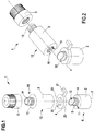
- the drop dispensing device 1 comprises a first container 2, a second container 3, a spacer 4 and a dispensing member 5.
- the first container 2 is formed as one piece.
- the first container 2 comprises a base portion 6 containing water for injection (WFI) 200 or a water-based solution for injection.
- the base portion 6 has a support base 7 and an opposite wall 8, from which a tubular element 9 extends transversely.
- the tubular element 9 is formed as one piece with the base portion 6 and has an open end portion 10.
- the tubular element 9 also has mechanical connection means 11 designed to allow engagement of the first and second containers 2, 3.
- the tubular element 9 may have a first, substantially smooth section intended to receive a spacer 4, and the mechanical connection means 11 may be defined along a second section of the tubular element 9.
- the mechanical connection means 11 may comprise at least one thread; alternatively, the connection means 11 may be of the snap-engaging or bayonet type.
- the attached figures show a tubular element 9 provided with threaded connection means defined by peripheral projections extending along an outer surface of the tubular element 9.
- the open end portion 10 is intended to allow, in certain operating conditions of the drop dispensing device 1, the passage of water for injection 200 through it and therefore out of the first container 2.
- the second container 3 contains a freeze-dried composition 300 comprising a drug, for example a nerve growth factor (NGF), and is configured to be engaged with the first container 2.
- a drug for example a nerve growth factor (NGF)
- NGF nerve growth factor
- the second container 3 is formed as one piece.
- the second container 3 has a base portion 12 and a collar 13 provided with an opening 14 and defined on the opposite side to the base portion 12.
- a seat 15 delimited laterally by a wall 16 and at one end by a piercible barrier 17 extending transversely with respect to the wall 16 is defined on the base portion 12 of the second container 3.
- the seat 15 may have a substantially cylindrical form; alternatively, the seat 15 may have a substantially prism-like or truncated prism or frustoconical form.
- the tubular element 9 is housed at least partially inside the seat 15.
- the wall 16 is intended to be engaged in a fluid-tight manner with the mechanical connection means 11 of the tubular element 9; for this purpose, the wall 16 may be shaped to match the connection means 11 of the tubular element 9 or may have in turn connection means.
- the attached figures show a second container 3, the wall 16 of which is shaped to match the thread of the tubular element 9.
- the first and second containers 2, 3 may be engaged or disengaged simply by screwing or unscrewing the second container 3 together with/from the first container 2.
- the first container 2 may be made of a material having a hardness greater than that of the material from which the second container 3 is made; for example, the first container 2 may be made of Teflon and the second container 3 may be made of polyethylene.
- the second container 3 may be deformed when the two containers are engaged together. In this way, when the tubular element 9 is inserted inside the seat 15 of the second container 3, the seat 15 itself is deformed so as to form a fluid-tight casing around the tubular element 9.
- a collar 13 is defined on the opposite side to the base portion 12 of the second container 3 defining the seat 15, the dispensing member 5 being engaged with said collar in the assembled condition of the drop dispensing device 1 (see Figure 3 ).
- the dispensing member 5 comprises a fluid dispensing opening 18 in fluid communication with the second container 3.
- the dispensing member 5 may consist for example of a dropper.
- the collar 13 and the dispensing member 5 may have mechanical connection means 19; the attached figures show, for example, a collar 13 provided with threaded connection means 19 and a dispensing member 5 internally shaped to match the threading of the collar 13 (see Figures 3 to 5 ).
- the connection means 19 may be of the snap-engaging or bayonet type.
- the dispensing member 5 is configured to allow dispensing of a multidose eye solution prepared from water for injection 200 and freeze-dried composition 300 comprising the drug, as will be described in greater detail below.
- the dispensing member 5 (shown only schematically in Figures 3 to 5 ) is configured to dispense drops of eye solution while maintaining a sterile environment inside the second container 3. Owing to this particular characteristic of the dispensing member 5 it is possible to design the dispensing device 1 so that the eye solution prepared with it may be multidose. In other words, from the moment the solution is prepared inside the dispensing device 1, the solution may be used for a prolonged period, up to 90 days after opening, and this usually allows a therapy cycle to be completed using a single dispensing device 1.
- a dispensing member 5 able to preserve the sterility of the container is for example commercially distributed under the trade name Novelia®, by Nemera La Verpilliere, France.
- the spacer 4 has moreover opposite and parallel bases 20 which, in the configuration where the spacer 4 is engaged with the first and second containers 2, 3, make contact with the first and second containers 2, 3 (see Figure 3 ). Therefore, in the assembled condition of the drop dispensing device 1, the spacer 4 is engaged between the first and second containers 2, 3.
- the contact between the bases 20 of the spacer 4 and, respectively, the first and second containers 2, 3 prevents the latter from being able to be inadvertently moved closer together.
- the spacer 4 may consist of an O-ring or resilient ring.
- the spacer 4 has a substantially annular form and comprises a gap 22 which allows the lateral extraction of the spacer even when the wall 16 of the second container 3 is engaged in a fluid-tight manner around the tubular element 9 of the first container 2. In this way the spacer 4 may be removed without disassembling the device 1, safeguarding therefore the sterility of the device itself 1 and its contents.
- the spacer 4 has a main body having substantially the same radial size compared to the first and second containers 2, 3. Providing the first container 2, second container 3 and spacer 4 with the same radial size is particularly advantageous since it increases the compactness of the eye-drop dispensing device 1.
- the spacer 4 comprises a lug 21 designed to allow easy movement thereof (see Figures 1-3 ).
- the spacer 4 is able to prevent, in the assembled condition of the drop dispensing device 1, the tubular element 9 from coming into contact with the piercible barrier 17.
- the piercible barrier 17 operates between a closed condition (barrier not perforated, see Figure 3 ), in which it prevents mixing of water for injection and freeze-dried composition 300 comprising the drug, and an open condition (barrier pierced or open, see Figure 5 ), in which it allows mixing of water for injection 200 and freeze-dried composition 300 comprising the drug.
- the piercible barrier 17 is in a closed condition in which it delimits at the top the seat 15 defined by the second container 3 and prevents mixing together of the substances contained respectively inside the first and second containers 2, 3.
- the tubular element 9 comes into contact with the piercible barrier 17, piercing it or causing opening thereof (see Figure 5).
- Figure 4 instead show a configuration of the drop dispensing device 1 in between the configuration shown in Figure 3 and that shown in Figure 5 , where the spacer 4 has been removed from the drop dispensing device 1, but the tubular element 9 does not act on the piercible barrier 17.
- the two substances contained inside the first and second containers 2, 3 may be mixed together by simply shaking the drop dispensing device 1. Mixing together of the two substances allows the preparation of a multidose eye solution.
- the multidose eye solution may therefore be dosed and dispensed by means of the dispensing member 5.
- the present disclosure relates moreover to a process for the production of a device 1 for dispensing eye drops, in accordance with Claim 1.
- the process does not fall under the scope of the claims.
- water for injection 200 or a water-based solution for injection is introduced inside the first container 2.
- the spacer 4 is engaged with the first container 2 around the tubular element 9; in this connection, see the first container/spacer assembly shown in Figure 2 .
- the second container 3 is engaged with the first container/spacer assembly; this engagement ensures a fluid-tight seal between the first container 2 and the second container 3 and prevents therefore the substance contained inside the first container 2 from coming out of the seat 15 inside which tubular element 9 is engaged in a fluid-tight manner.
- the fluid is prevented from coming out of the first container 2 by the provision of the piercible barrier 17 which closes the seat 15 at the top and by the fluid-tight engagement between tubular element 9 and wall 16 laterally delimiting the seat 15.
- the first container 2 contains water for injection 200 and is engaged in a fluid-tight manner with the second container 3, and the second container 3 contains the solution or dispersion comprising the drug; the second container 3 is open in the region of the collar 13.
- the first container/second container/spacer assembly is then subjected to a freeze-drying atmosphere; for this purpose it may be inserted inside a freeze-drying chamber.
- the freeze-drying atmosphere may for example have a temperature of between -90 °C and -20 °C, preferably between -50°C and -30°C for primary drying and a temperature of between -15°C and +35°C, preferably of between -5°C and +15°C for secondary drying; the vacuum pressure during the process may have a value of between 20 and 300 ⁇ bar (microbar).
- the freeze-drying atmosphere allows freeze-drying of the solution or dispersion comprising the drug and allows therefore a freeze-dried composition 300 comprising the drug to be obtained.
- the freeze-drying operation removes the water content of the solution or dispersion comprising the drug; this water content flows out from the second container 3 through the opening 14 of the collar 13. Since the first container 2 is engaged in a fluid-tight manner with the second container 3, the freeze-drying atmosphere instead does not allow freeze-drying of the water for injection 200 contained in the first container 2; the water for injection 200 freezes inside the first container 2, without however being able to flow out of it or the seat 15 inside which the tubular element 9 is engaged. Since it is confined inside the first container, the water for injection 200 returns to the liquid state following removal of the freeze-drying atmosphere.
- a dispensing member 5 is engaged with the collar 13 of the second container 3 so as to obtain a device 1 for dispensing eye drops
- the dispensing member 5 may be engaged with the collar 13 by simply screwing it together therewith. Engagement of the dispensing member 5 may be performed in a sterile environment.
- the device 1 for dispensing eye drops thus obtained is shown in Figure 3 .
- the process then involves a step for packaging the eye-drop dispensing device 1; the packaging step is preferably performed in a nitrogen-containing atmosphere.
- the packaging step may involve placing the eye-drop dispensing device 1 inside a further sterile or hermetically sealed container.
- the first container 2 and the second container 3 are sterilized first of all.
- This step may also involve the sterilization of the dispensing member 5 and the spacer 4.
- the sterilization may be of the type using gamma rays or ethylene oxide or may be of the type using steam performed in an autoclave.
- one or more of the steps following sterilization may be performed in a sterile environment. Following sterilization, water for injection 200 is introduced inside the first container 2. A spacer 4 is then engaged with the first container 2 around the tubular element 9. A solution or dispersion comprising the drug is introduced inside the second container 3; during this step, the second container 3 is not assembled with the first container 2.
- the second container 3 is then subjected to a freeze-drying atmosphere which has the same temperature and pressure values described above; in this way freeze-drying of the solution or dispersion comprising the drug contained inside the second container 3 occurs.
- the first container 2 is not subjected to the freeze-drying atmosphere.
- the second container 3 therefore contains a freeze-dried composition 300 comprising the drug.
- the dispensing member 5 is engaged with the collar 13 of the second container 3; the engagement of the dispensing member 5 may be performed in a sterile environment.
- the second container/dispensing member assembly is engaged with the first container/spacer assembly. This assembly operation may be performed so that the first container 2 is connected in a fluid-tight manner with the second container 3 (as described above) in order to prevent leakage of fluid between said containers.
- the device 1 for dispensing eye drops thus obtained is shown in Figure 3 .
- the process then envisages a step for packaging the eye-drop dispensing device 1; the packaging step is preferably performed in a nitrogen-containing atmosphere.
- the packaging step may involve placing the eye-drop dispensing device 1 inside a further sterile or hermetically sealed container.
- the use of the eye-drop dispensing device 1 will be described below.
- the use of the eye-drop dispensing device 1 involves substantially the preparation of a multidose eye solution.
- the spacer 4 is removed laterally from the eye-drop dispensing device 1. Owing to the presence of the gap 22, the spacer 4 may be removed without disengaging the first container 2 from the second container/dispensing member assembly. At this point, the first container 2 and the second container 3 are moved relatively closer together; for example, this operation may be performed by means of rotational movement of the second container 3 with respect to the first container 2 (as shown in Figure 5 ) or vice versa. The movement of the first and second containers 2, 3 is made possible owing to the provision of the connection means described above.
- This movement allows the barrier 17 of the second container 3 to be pierced by means of the tubular element 9 of the first container 2 (see Figure 5 ). After piercing the barrier 17, in order to obtain the eye solution, mixing of water for injection 200 and freeze-dried composition 300 comprising the drug, for example nerve growth factor, is performed.
- the freeze-dried composition 300 comprising the drug is introduced inside the second container 3, with which the dispensing member 5 is engaged.
- water for injection may be made to flow out of the first container 2 into the second container 3 and consequently mixing is performed mainly inside the second container 3, thus avoiding having the freeze-dried composition 300 comprising the drug inside the first container 2.
- dosing and subsequent application of the eye drops is performed by dosing them by means of the dispensing member 5.
- the application of the eye drops thus prepared may be repeated for several days, up to a maximum of 90 days.
Landscapes
- Health & Medical Sciences (AREA)
- Engineering & Computer Science (AREA)
- Veterinary Medicine (AREA)
- Mechanical Engineering (AREA)
- Life Sciences & Earth Sciences (AREA)
- Animal Behavior & Ethology (AREA)
- General Health & Medical Sciences (AREA)
- Public Health (AREA)
- Heart & Thoracic Surgery (AREA)
- Ophthalmology & Optometry (AREA)
- Biomedical Technology (AREA)
- Vascular Medicine (AREA)
- Pharmacology & Pharmacy (AREA)
- Hematology (AREA)
- Medical Preparation Storing Or Oral Administration Devices (AREA)
- Package Specialized In Special Use (AREA)
Claims (15)
- Dispositif (1) pour la distribution de gouttes ophtalmiques, comprenant :- un premier récipient (2) contenant une première substance liquide,- un second récipient (3) contenant une seconde substance lyophilisée comprenant un agent thérapeutique, et- une entretoise (4) agencée entre les premier et second récipients (2, 3),le premier récipient (2) comprenant un élément tubulaire (9) ayant une partie d'extrémité (10) ouverte de façon à permettre à la première substance de s'écouler à travers ladite partie d'extrémité (10) ouverte,
le second récipient (3) comprenant une barrière apte à être percée (17) destinée à empêcher le mélange de la première substance avec la seconde substance et une paroi (16) configurée pour être mise en prise d'une manière étanche aux fluides autour de l'élément tubulaire (9),
dans lequel l'entretoise (4) possède des bases opposées sensiblement parallèles (20) agencées entre et en contact avec les premier et second récipients (2, 3), et dans lequel l'entretoise (4) est mobile entre une position assemblée, dans laquelle elle empêche l'élément tubulaire (9) de venir en contact avec la barrière apte à être percée (17), et une position retirée, dans laquelle un mouvement relatif des premier et second récipients (2, 3) est permis et l'élément tubulaire (9) vient en contact avec la barrière apte à être percée (17), en la perçant. - Dispositif (1) selon la revendication 1, dans lequel la barrière apte à être percée (17) est configurée pour fonctionner entre au moins un état fermé, dans lequel le mélange de la première substance avec la seconde substance est empêché, et un état ouvert, dans lequel le mélange de la première substance avec la seconde substance est permis.
- Dispositif (1) selon la revendication précédente, dans lequel la barrière apte à être percée (17) est mise en prise avec le second récipient (3) à la fois dans l'état fermé et dans l'état ouvert et dans lequel la barrière apte à être percée (17) est agencée à proximité de ladite paroi (16) du second récipient (3).
- Dispositif (1) selon la revendication 1 ou la revendication 2 ou la revendication 3, dans lequel l'élément tubulaire (9) comprend des moyens (11) pour relier mécaniquement ensemble les premier et second récipients (2, 3) configurés pour venir en prise d'une manière étanche aux fluides avec ladite paroi (16) du second récipient (3), la partie d'extrémité (10) de l'élément tubulaire (9) étant configurée pour percer la barrière (17), les moyens (11) de liaison mécanique de l'élément tubulaire (9) étant configurés pour permettre le mouvement relatif des premier et second récipients (2, 3) entre au moins une position dans laquelle l'élément tubulaire (9) est espacé de la barrière apte à être percée (17) et la position dans laquelle l'élément tubulaire (9) agit sur la barrière apte à être percée (17) de façon à la percer.
- Dispositif (1) selon la revendication précédente, dans lequel le second récipient (3) comprend une partie de base (12) définissant un siège (15), le siège (15) étant délimité à une extrémité par la barrière apte à être percée (17) et étant délimité latéralement par ladite paroi (16) du second récipient (3), ladite paroi (16) étant au moins partiellement façonnée pour correspondre aux moyens (11) de liaison mécanique de l'élément tubulaire (9) de façon à venir en prise d'une manière étanche aux fluides autour dudit élément tubulaire (9).
- Dispositif (1) selon la revendication 4 ou la revendication 5, dans lequel les moyens (11) de liaison mécanique de l'élément tubulaire (9) comprennent des saillies périphériques configurées pour venir en prise d'une manière étanche aux fluides sur ladite paroi (16) du second récipient (3) et dans lequel les moyens (11) de liaison mécanique de l'élément tubulaire (9) sont du type ayant au moins un filetage ou du type à mise en prise par encliquetage ou du type à baïonnette.
- Dispositif (1) selon la revendication 4 ou la revendication 5 ou la revendication 6, dans lequel ladite paroi (16) du second récipient (3) est configurée pour être mise en prise d'une manière étanche aux fluides avec lesdits moyens (11) de liaison de l'élément tubulaire (9).
- Dispositif (1) selon l'une quelconque des revendications précédentes, dans lequel le premier récipient (2) comprend une partie de base (6) contenant la première substance liquide, ledit élément tubulaire (9) étant formé d'un seul tenant avec la partie de base (6), la partie de base (6) comprenant une base de support sensiblement plate (7) et une paroi opposée (8) parallèle à la base de support (7), l'élément tubulaire (9) faisant saille de manière transversale à partie de ladite paroi opposée (8).
- Dispositif (1) selon l'une quelconque des revendications précédentes, dans lequel le premier récipient (2) est formé d'un seul tenant et dans lequel le second récipient (3) est formé d'un seul tenant.
- Dispositif (1) selon l'une quelconque des revendications précédentes, dans lequel l'élément tubulaire (9) possède une première section ayant une surface externe sensiblement lisse configurée pour recevoir l'entretoise (4) et une seconde section comprenant des moyens (11) de liaison mécanique configurés pour mettre en prise l'élément tubulaire (9) avec ladite paroi (16) du second récipient (3), et dans lequel :- le second récipient (3) comprend la barrière apte à être percée (17) et une partie de base (12) définissant un siège (15), le siège (15) étant délimité à une extrémité par la barrière apte à être percée (17) et étant latéralement délimité par ladite paroi (16) du second récipient (3), ladite paroi (16) étant au moins partiellement façonnée pour correspondre à la seconde section de l'élément tubulaire (9) de façon à venir en prise d'une manière étanche aux fluides autour dudit élément tubulaire (9).
- Dispositif (1) selon l'une quelconque des revendications précédentes, dans lequel l'entretoise (4) agencée entre les premier et second récipients (2, 3) possède une forme sensiblement annulaire comprenant un espace (22) qui permet son extraction latérale même lorsque la paroi (16) du second récipient (3) est mise en prise d'une manière étanche aux fluides autour de l'élément tubulaire (9) du premier récipient (2).
- Dispositif (1) selon l'une quelconque des revendications précédentes, dans lequel le second récipient (3) comprend une partie de base (12) et une collerette (13) agencée sur le côté opposé à la partie de base (12), la collerette (13) étant destinée à être reliée à un organe de distribution (5), tel qu'un compte-gouttes, la collerette (13) ayant une ouverture (14) destinée à permettre, pendant l'utilisation du dispositif (1), le passage d'un fluide.
- Dispositif (1) selon la revendication précédente, comprenant un organe de distribution (5), tel qu'un compte-gouttes, mis en prise avec la collerette (13) du second récipient (3) et configuré pour distribuer des gouttes tout en maintenant un environnement stérile dans le second récipient (3), ledit organe de distribution (5) et ladite collerette (13) comprenant des moyens de liaison mécanique du type ayant au moins un filetage ou du type à mise en prise par encliquetage ou du type à baïonnette.
- Dispositif (1) selon l'une quelconque des revendications précédentes, dans lequel le premier récipient (2) est constitué d'un premier matériau ayant une dureté supérieure à la dureté du matériau du second récipient (3).
- Dispositif (1) selon l'une quelconque des revendications précédentes, dans lequel le premier récipient (2) contient de l'eau ou une solution aqueuse pour une injection (200) et le second récipient (3) contient une composition lyophilisée (300) comprenant un médicament d'une nature chimique et/ou biotechnologique, de préférence comprenant un facteur de croissance nerveuse.
Applications Claiming Priority (2)
| Application Number | Priority Date | Filing Date | Title |
|---|---|---|---|
| ITMI20150511 | 2015-04-10 | ||
| PCT/IB2016/051963 WO2016162812A1 (fr) | 2015-04-10 | 2016-04-07 | Dispositif de distribution de gouttes oculaires |
Publications (2)
| Publication Number | Publication Date |
|---|---|
| EP3280377A1 EP3280377A1 (fr) | 2018-02-14 |
| EP3280377B1 true EP3280377B1 (fr) | 2021-09-08 |
Family
ID=53673177
Family Applications (1)
| Application Number | Title | Priority Date | Filing Date |
|---|---|---|---|
| EP16719520.5A Active EP3280377B1 (fr) | 2015-04-10 | 2016-04-07 | Dispositif de distribution de gouttes oculaires |
Country Status (15)
| Country | Link |
|---|---|
| US (1) | US11103379B2 (fr) |
| EP (1) | EP3280377B1 (fr) |
| JP (1) | JP2018515178A (fr) |
| KR (1) | KR20170141683A (fr) |
| CN (1) | CN107645944A (fr) |
| AU (1) | AU2016244394B2 (fr) |
| BR (1) | BR112017021471A2 (fr) |
| CA (1) | CA2981698A1 (fr) |
| EA (1) | EA037496B1 (fr) |
| IL (1) | IL254677B (fr) |
| MA (1) | MA41906A (fr) |
| MX (1) | MX2017012994A (fr) |
| SG (1) | SG11201707847SA (fr) |
| WO (1) | WO2016162812A1 (fr) |
| ZA (1) | ZA201706548B (fr) |
Families Citing this family (9)
| Publication number | Priority date | Publication date | Assignee | Title |
|---|---|---|---|---|
| JP7118540B2 (ja) * | 2018-08-30 | 2022-08-16 | 株式会社吉野工業所 | 混合吐出容器 |
| DE102019203857A1 (de) * | 2019-03-21 | 2020-09-24 | Henkel Ag & Co. Kgaa | Verpackungssystem für zumindest eine Produktzubereitungskomponente sowie zugehöriges Verfahren zur Handhabung der Produktzubereitungskomponente |
| DE102019203858A1 (de) * | 2019-03-21 | 2020-09-24 | Henkel Ag & Co. Kgaa | Verpackungssystem für zumindest eine Produktzubereitungskomponente sowie zugehöriges Verfahren zur Handhabung der Produktzubereitungskomponente |
| FR3096040B1 (fr) * | 2019-05-17 | 2021-09-24 | Aptar France Sas | Dispositif de distribution de produit fluide |
| US10661968B1 (en) * | 2019-06-20 | 2020-05-26 | Elc Management Llc | Container system for mixing and dispensing |
| HRP20241431T1 (hr) | 2019-09-17 | 2024-12-20 | Chiesi Farmaceutici S.P.A. | Mutant ngf za upotrebu u liječenju ili prevenciji oftalmoloških poremećaja |
| CN116135217A (zh) * | 2021-11-17 | 2023-05-19 | 莱逸生物科技有限公司 | 用于眼部的复方组成物及其套组与应用 |
| CN117163472B (zh) * | 2023-09-07 | 2025-02-11 | 万通(苏州)定量阀系统有限公司 | 一种可替换的分配装置 |
| CN117735099B (zh) * | 2023-12-22 | 2025-12-12 | 山东润君药业有限公司 | 一种医药固液分离包装容器 |
Family Cites Families (45)
| Publication number | Priority date | Publication date | Assignee | Title |
|---|---|---|---|---|
| US3354882A (en) | 1964-10-26 | 1967-11-28 | Pharmaseal Lab | Hypodermic syringe |
| US3857423A (en) | 1971-12-27 | 1974-12-31 | W Ronca | Topical medicament kit with interlocking components |
| US4153057A (en) | 1975-07-24 | 1979-05-08 | Merck Patent Gesellschaft Mit Beschrankter Haftung | Stopper for two-chamber mixing syringe |
| FR2427960A1 (fr) * | 1978-06-06 | 1980-01-04 | Dehais Claude | Manchon pour etablir une communication temporaire entre deux recipients |
| JPS6130699U (ja) | 1984-07-26 | 1986-02-24 | 三菱鉛筆株式会社 | 注入器 |
| IT220400Z2 (it) | 1990-05-29 | 1993-09-21 | Farmigea Spa | Contenitori di prodotti farmaceutici liofilizzati |
| JPH04106266U (ja) * | 1991-02-18 | 1992-09-14 | 千寿製薬株式会社 | 二剤混合滴下用容器 |
| US5217433A (en) * | 1991-05-24 | 1993-06-08 | Merck & Co., Inc. | Medication container for mixing two components |
| FI934118A0 (fi) | 1992-01-21 | 1993-09-20 | Gabriel Meyer | Anordning foer lagring av vaetskeformigt laekemedel och utmatning av oegondroppar |
| FR2722765B1 (fr) | 1994-07-25 | 1996-08-23 | Oreal | Recipient permettant le stockage d'au moins deux produits, le melange de ces produits et la distribution du melange ainsi obtenu |
| IT1277806B1 (it) | 1995-01-25 | 1997-11-12 | Levetta Project Sas | Confezione a flacone per liquidi da prelevare in dosi |
| GB9505523D0 (en) | 1995-03-18 | 1995-05-03 | Wellcome Found | Lyophilization process |
| US5685845A (en) | 1995-07-11 | 1997-11-11 | Becton, Dickinson And Company | Sterile resealable vial connector assembly |
| DE19635833C2 (de) * | 1996-09-04 | 1998-08-06 | Henkel Kgaa | Zwei-Komponenten-Behälter |
| GB9701413D0 (en) | 1997-01-24 | 1997-03-12 | Smithkline Beecham Biolog | Novel device |
| IT1291892B1 (it) * | 1997-04-24 | 1999-01-21 | Alessandro Lambiase | Uso del nerve growth factor nella conservazione di cornee in coltura, nella produzione di tessuti corneali e congiuntivali in vitro e nella |
| IT1291848B1 (it) | 1997-05-02 | 1999-01-21 | Project S A S Di Menichelli Ma | Otturatore per flaconi con dispositivo per il prelievo di quantitativi dosati del liquido contenuto in detti flaconi |
| JP4095770B2 (ja) * | 1997-08-27 | 2008-06-04 | ペンタファルム アクチェンゲゼルシャフト | 凍結乾燥された製品のための2つのバイアルの結合装置 |
| CN1149063C (zh) * | 1997-08-27 | 2004-05-12 | 彭特法姆股份公司 | 用于冻干物的双管形瓶连接装置 |
| US6425885B1 (en) | 1999-12-20 | 2002-07-30 | Ultradent Products, Inc. | Hydraulic syringe |
| JP4141156B2 (ja) | 2002-03-15 | 2008-08-27 | 日本ベクトン・ディッキンソン株式会社 | プランジャ後退制限機構付きプレフィルドシリンジ |
| EP1549328A4 (fr) | 2002-09-18 | 2009-07-08 | Emiliano Ghinelli | Utilisation d'une composition a base de membrane amniotique humaine dans la prophylaxie et le traitement de maladies et d'etats pathologiques de l'oeil et de la peau |
| US20070181449A1 (en) * | 2004-01-19 | 2007-08-09 | Keiji Hamamoto | Guidance route search device, navigation device, and method of searching guidance route |
| US20060049127A1 (en) | 2004-09-09 | 2006-03-09 | Liran Katz | Container |
| JP4808415B2 (ja) | 2005-02-01 | 2011-11-02 | 大成化工株式会社 | 2成分混合容器 |
| US7563256B2 (en) * | 2006-03-30 | 2009-07-21 | Isaac Hearne | Cannula tip eye drop dispenser |
| DE602008002896D1 (de) | 2007-02-05 | 2010-11-18 | Novo Nordisk As | Injektionsknopf |
| DE202007005394U1 (de) | 2007-04-13 | 2007-08-09 | B. Braun Melsungen Ag | Sicherheitsspritze |
| CN101284006A (zh) * | 2007-04-13 | 2008-10-15 | 华北制药集团新药研究开发有限责任公司 | 一种治疗眼部疾病的药物组合物 |
| US8151985B2 (en) * | 2007-06-22 | 2012-04-10 | Owoc Greg J | Containers for storing at least two substances for subsequent mixing |
| EP2259839B1 (fr) | 2008-03-04 | 2015-12-23 | Infusion Innovations, Inc. | Dispositifs, ensembles et procédés pour commander un écoulement de fluide |
| FR2930140B1 (fr) | 2008-04-17 | 2011-04-22 | Philippe Perovitch | Dispositif pour la conservation, la preparation extemporanee et l'administration d'un faible dosage de principe actif |
| US20110190709A1 (en) | 2008-06-17 | 2011-08-04 | Denki Kagaku Kogyo Kabushiki Kaisha | Injector |
| CN102595963B (zh) | 2009-10-19 | 2015-06-17 | 株式会社衍宇 | 能够定量吸取的滴管以及具备该滴管的化妆品容器 |
| EP2665502B1 (fr) | 2011-01-17 | 2020-03-25 | AktiVax, Inc. | Cartouche aseptique et agencement de distribution |
| CN202027906U (zh) * | 2011-03-21 | 2011-11-09 | 山东省警官总医院 | 固液分离即混合两腔式药瓶 |
| CN102274122A (zh) * | 2011-05-20 | 2011-12-14 | 海南卫康制药(潜山)有限公司 | 适用于注射剂药品的包装瓶 |
| CN202113430U (zh) | 2011-06-13 | 2012-01-18 | 李俊玲 | 一种新型麻醉用注射器 |
| JP2015503992A (ja) | 2012-01-17 | 2015-02-05 | ドクター ピー インスティチュート エルエルシー | 複数回投与用シリンジおよび方法 |
| LT3679922T (lt) | 2012-06-01 | 2021-10-25 | Novartis Ag | Švirkštas |
| DE202013000688U1 (de) | 2012-07-03 | 2013-03-05 | Novartis Ag | Glas-Spritze |
| CN202982801U (zh) | 2012-12-13 | 2013-06-12 | 上海康德莱企业发展集团股份有限公司 | 一种高精度0.05毫升注射器 |
| US9408981B2 (en) | 2013-03-10 | 2016-08-09 | Bayer Healthcare Llc | Adjustable volume syringe |
| US9101713B2 (en) | 2013-03-12 | 2015-08-11 | Bayer Medical Care Inc. | Constant force syringe |
| FR3023172A1 (fr) | 2014-07-07 | 2016-01-08 | Jls Production | Seringue comprenant une membrane et une bague de fixation de ladite membrane |
-
2016
- 2016-04-06 MA MA041906A patent/MA41906A/fr unknown
- 2016-04-07 AU AU2016244394A patent/AU2016244394B2/en not_active Ceased
- 2016-04-07 CA CA2981698A patent/CA2981698A1/fr not_active Abandoned
- 2016-04-07 EA EA201792270A patent/EA037496B1/ru unknown
- 2016-04-07 WO PCT/IB2016/051963 patent/WO2016162812A1/fr not_active Ceased
- 2016-04-07 JP JP2017553145A patent/JP2018515178A/ja not_active Ceased
- 2016-04-07 US US15/564,280 patent/US11103379B2/en not_active Expired - Fee Related
- 2016-04-07 MX MX2017012994A patent/MX2017012994A/es unknown
- 2016-04-07 CN CN201680027261.XA patent/CN107645944A/zh active Pending
- 2016-04-07 SG SG11201707847SA patent/SG11201707847SA/en unknown
- 2016-04-07 EP EP16719520.5A patent/EP3280377B1/fr active Active
- 2016-04-07 BR BR112017021471-7A patent/BR112017021471A2/pt not_active IP Right Cessation
- 2016-04-07 KR KR1020177030478A patent/KR20170141683A/ko not_active Ceased
-
2017
- 2017-09-25 IL IL254677A patent/IL254677B/en unknown
- 2017-09-28 ZA ZA2017/06548A patent/ZA201706548B/en unknown
Also Published As
| Publication number | Publication date |
|---|---|
| MA41906A (fr) | 2018-02-13 |
| EA037496B1 (ru) | 2021-04-05 |
| US20180133053A1 (en) | 2018-05-17 |
| AU2016244394B2 (en) | 2021-02-25 |
| BR112017021471A2 (pt) | 2018-07-03 |
| SG11201707847SA (en) | 2017-10-30 |
| CA2981698A1 (fr) | 2016-10-13 |
| AU2016244394A1 (en) | 2017-10-19 |
| US11103379B2 (en) | 2021-08-31 |
| WO2016162812A1 (fr) | 2016-10-13 |
| EA201792270A1 (ru) | 2018-07-31 |
| IL254677B (en) | 2021-08-31 |
| EP3280377A1 (fr) | 2018-02-14 |
| KR20170141683A (ko) | 2017-12-26 |
| IL254677A0 (en) | 2017-11-30 |
| JP2018515178A (ja) | 2018-06-14 |
| MX2017012994A (es) | 2018-05-22 |
| HK1242958A1 (zh) | 2018-07-06 |
| CN107645944A (zh) | 2018-01-30 |
| ZA201706548B (en) | 2019-01-30 |
Similar Documents
| Publication | Publication Date | Title |
|---|---|---|
| EP3280377B1 (fr) | Dispositif de distribution de gouttes oculaires | |
| EP3280654B1 (fr) | Procédé de fabrication d'un dispositif de distribution pour gouttes ophtalmiques | |
| EP2512398A1 (fr) | Dispositif de transfert de médicament liquide avec adaptateur de flacon à aération | |
| US12383682B2 (en) | Double chamber device for point of use mixing | |
| DK3174581T3 (en) | Multi-chamber container | |
| CN104507820A (zh) | 具有用无针注射器可刺入的和可自动重新密封的气密外壳的用于医药和/或营养活性物质的瓶子 | |
| HK1242958B (en) | Dispensing device for eye drops | |
| HK1243048B (en) | Method for manufacturing a dispensing device for eye drops | |
| KR101441855B1 (ko) | 수액연결장치 및 그 제조방법 | |
| HK1238587A1 (en) | Multi-chambered vessels | |
| HK1238587B (en) | Multi-chambered vessels |
Legal Events
| Date | Code | Title | Description |
|---|---|---|---|
| STAA | Information on the status of an ep patent application or granted ep patent |
Free format text: STATUS: THE INTERNATIONAL PUBLICATION HAS BEEN MADE |
|
| PUAI | Public reference made under article 153(3) epc to a published international application that has entered the european phase |
Free format text: ORIGINAL CODE: 0009012 |
|
| STAA | Information on the status of an ep patent application or granted ep patent |
Free format text: STATUS: REQUEST FOR EXAMINATION WAS MADE |
|
| 17P | Request for examination filed |
Effective date: 20170921 |
|
| AK | Designated contracting states |
Kind code of ref document: A1 Designated state(s): AL AT BE BG CH CY CZ DE DK EE ES FI FR GB GR HR HU IE IS IT LI LT LU LV MC MK MT NL NO PL PT RO RS SE SI SK SM TR |
|
| AX | Request for extension of the european patent |
Extension state: BA ME |
|
| REG | Reference to a national code |
Ref country code: HK Ref legal event code: DE Ref document number: 1242958 Country of ref document: HK |
|
| STAA | Information on the status of an ep patent application or granted ep patent |
Free format text: STATUS: EXAMINATION IS IN PROGRESS |
|
| 17Q | First examination report despatched |
Effective date: 20191119 |
|
| GRAP | Despatch of communication of intention to grant a patent |
Free format text: ORIGINAL CODE: EPIDOSNIGR1 |
|
| STAA | Information on the status of an ep patent application or granted ep patent |
Free format text: STATUS: GRANT OF PATENT IS INTENDED |
|
| INTG | Intention to grant announced |
Effective date: 20210521 |
|
| RIN1 | Information on inventor provided before grant (corrected) |
Inventor name: GENTILE, MARCO MARIA |
|
| GRAS | Grant fee paid |
Free format text: ORIGINAL CODE: EPIDOSNIGR3 |
|
| GRAA | (expected) grant |
Free format text: ORIGINAL CODE: 0009210 |
|
| STAA | Information on the status of an ep patent application or granted ep patent |
Free format text: STATUS: THE PATENT HAS BEEN GRANTED |
|
| AK | Designated contracting states |
Kind code of ref document: B1 Designated state(s): AL AT BE BG CH CY CZ DE DK EE ES FI FR GB GR HR HU IE IS IT LI LT LU LV MC MK MT NL NO PL PT RO RS SE SI SK SM TR |
|
| REG | Reference to a national code |
Ref country code: GB Ref legal event code: FG4D |
|
| REG | Reference to a national code |
Ref country code: AT Ref legal event code: REF Ref document number: 1427911 Country of ref document: AT Kind code of ref document: T Effective date: 20210915 Ref country code: CH Ref legal event code: EP |
|
| REG | Reference to a national code |
Ref country code: IE Ref legal event code: FG4D |
|
| REG | Reference to a national code |
Ref country code: DE Ref legal event code: R096 Ref document number: 602016063408 Country of ref document: DE |
|
| REG | Reference to a national code |
Ref country code: LT Ref legal event code: MG9D |
|
| REG | Reference to a national code |
Ref country code: NL Ref legal event code: MP Effective date: 20210908 |
|
| PG25 | Lapsed in a contracting state [announced via postgrant information from national office to epo] |
Ref country code: SE Free format text: LAPSE BECAUSE OF FAILURE TO SUBMIT A TRANSLATION OF THE DESCRIPTION OR TO PAY THE FEE WITHIN THE PRESCRIBED TIME-LIMIT Effective date: 20210908 Ref country code: RS Free format text: LAPSE BECAUSE OF FAILURE TO SUBMIT A TRANSLATION OF THE DESCRIPTION OR TO PAY THE FEE WITHIN THE PRESCRIBED TIME-LIMIT Effective date: 20210908 Ref country code: BG Free format text: LAPSE BECAUSE OF FAILURE TO SUBMIT A TRANSLATION OF THE DESCRIPTION OR TO PAY THE FEE WITHIN THE PRESCRIBED TIME-LIMIT Effective date: 20211208 Ref country code: LT Free format text: LAPSE BECAUSE OF FAILURE TO SUBMIT A TRANSLATION OF THE DESCRIPTION OR TO PAY THE FEE WITHIN THE PRESCRIBED TIME-LIMIT Effective date: 20210908 Ref country code: NO Free format text: LAPSE BECAUSE OF FAILURE TO SUBMIT A TRANSLATION OF THE DESCRIPTION OR TO PAY THE FEE WITHIN THE PRESCRIBED TIME-LIMIT Effective date: 20211208 Ref country code: FI Free format text: LAPSE BECAUSE OF FAILURE TO SUBMIT A TRANSLATION OF THE DESCRIPTION OR TO PAY THE FEE WITHIN THE PRESCRIBED TIME-LIMIT Effective date: 20210908 Ref country code: ES Free format text: LAPSE BECAUSE OF FAILURE TO SUBMIT A TRANSLATION OF THE DESCRIPTION OR TO PAY THE FEE WITHIN THE PRESCRIBED TIME-LIMIT Effective date: 20210908 Ref country code: HR Free format text: LAPSE BECAUSE OF FAILURE TO SUBMIT A TRANSLATION OF THE DESCRIPTION OR TO PAY THE FEE WITHIN THE PRESCRIBED TIME-LIMIT Effective date: 20210908 |
|
| REG | Reference to a national code |
Ref country code: AT Ref legal event code: MK05 Ref document number: 1427911 Country of ref document: AT Kind code of ref document: T Effective date: 20210908 |
|
| PG25 | Lapsed in a contracting state [announced via postgrant information from national office to epo] |
Ref country code: LV Free format text: LAPSE BECAUSE OF FAILURE TO SUBMIT A TRANSLATION OF THE DESCRIPTION OR TO PAY THE FEE WITHIN THE PRESCRIBED TIME-LIMIT Effective date: 20210908 Ref country code: GR Free format text: LAPSE BECAUSE OF FAILURE TO SUBMIT A TRANSLATION OF THE DESCRIPTION OR TO PAY THE FEE WITHIN THE PRESCRIBED TIME-LIMIT Effective date: 20211209 |
|
| PG25 | Lapsed in a contracting state [announced via postgrant information from national office to epo] |
Ref country code: AT Free format text: LAPSE BECAUSE OF FAILURE TO SUBMIT A TRANSLATION OF THE DESCRIPTION OR TO PAY THE FEE WITHIN THE PRESCRIBED TIME-LIMIT Effective date: 20210908 |
|
| VS25 | Lapsed in a validation state [announced via postgrant information from nat. office to epo] |
Ref country code: MD Free format text: LAPSE BECAUSE OF FAILURE TO SUBMIT A TRANSLATION OF THE DESCRIPTION OR TO PAY THE FEE WITHIN THE PRESCRIBED TIME-LIMIT Effective date: 20210908 |
|
| PG25 | Lapsed in a contracting state [announced via postgrant information from national office to epo] |
Ref country code: IS Free format text: LAPSE BECAUSE OF FAILURE TO SUBMIT A TRANSLATION OF THE DESCRIPTION OR TO PAY THE FEE WITHIN THE PRESCRIBED TIME-LIMIT Effective date: 20220108 Ref country code: SM Free format text: LAPSE BECAUSE OF FAILURE TO SUBMIT A TRANSLATION OF THE DESCRIPTION OR TO PAY THE FEE WITHIN THE PRESCRIBED TIME-LIMIT Effective date: 20210908 Ref country code: SK Free format text: LAPSE BECAUSE OF FAILURE TO SUBMIT A TRANSLATION OF THE DESCRIPTION OR TO PAY THE FEE WITHIN THE PRESCRIBED TIME-LIMIT Effective date: 20210908 Ref country code: RO Free format text: LAPSE BECAUSE OF FAILURE TO SUBMIT A TRANSLATION OF THE DESCRIPTION OR TO PAY THE FEE WITHIN THE PRESCRIBED TIME-LIMIT Effective date: 20210908 Ref country code: PT Free format text: LAPSE BECAUSE OF FAILURE TO SUBMIT A TRANSLATION OF THE DESCRIPTION OR TO PAY THE FEE WITHIN THE PRESCRIBED TIME-LIMIT Effective date: 20220110 Ref country code: PL Free format text: LAPSE BECAUSE OF FAILURE TO SUBMIT A TRANSLATION OF THE DESCRIPTION OR TO PAY THE FEE WITHIN THE PRESCRIBED TIME-LIMIT Effective date: 20210908 Ref country code: NL Free format text: LAPSE BECAUSE OF FAILURE TO SUBMIT A TRANSLATION OF THE DESCRIPTION OR TO PAY THE FEE WITHIN THE PRESCRIBED TIME-LIMIT Effective date: 20210908 Ref country code: EE Free format text: LAPSE BECAUSE OF FAILURE TO SUBMIT A TRANSLATION OF THE DESCRIPTION OR TO PAY THE FEE WITHIN THE PRESCRIBED TIME-LIMIT Effective date: 20210908 Ref country code: CZ Free format text: LAPSE BECAUSE OF FAILURE TO SUBMIT A TRANSLATION OF THE DESCRIPTION OR TO PAY THE FEE WITHIN THE PRESCRIBED TIME-LIMIT Effective date: 20210908 Ref country code: AL Free format text: LAPSE BECAUSE OF FAILURE TO SUBMIT A TRANSLATION OF THE DESCRIPTION OR TO PAY THE FEE WITHIN THE PRESCRIBED TIME-LIMIT Effective date: 20210908 |
|
| REG | Reference to a national code |
Ref country code: DE Ref legal event code: R097 Ref document number: 602016063408 Country of ref document: DE |
|
| PLBE | No opposition filed within time limit |
Free format text: ORIGINAL CODE: 0009261 |
|
| STAA | Information on the status of an ep patent application or granted ep patent |
Free format text: STATUS: NO OPPOSITION FILED WITHIN TIME LIMIT |
|
| PG25 | Lapsed in a contracting state [announced via postgrant information from national office to epo] |
Ref country code: DK Free format text: LAPSE BECAUSE OF FAILURE TO SUBMIT A TRANSLATION OF THE DESCRIPTION OR TO PAY THE FEE WITHIN THE PRESCRIBED TIME-LIMIT Effective date: 20210908 |
|
| 26N | No opposition filed |
Effective date: 20220609 |
|
| PG25 | Lapsed in a contracting state [announced via postgrant information from national office to epo] |
Ref country code: SI Free format text: LAPSE BECAUSE OF FAILURE TO SUBMIT A TRANSLATION OF THE DESCRIPTION OR TO PAY THE FEE WITHIN THE PRESCRIBED TIME-LIMIT Effective date: 20210908 |
|
| REG | Reference to a national code |
Ref country code: DE Ref legal event code: R119 Ref document number: 602016063408 Country of ref document: DE |
|
| REG | Reference to a national code |
Ref country code: CH Ref legal event code: PL |
|
| GBPC | Gb: european patent ceased through non-payment of renewal fee |
Effective date: 20220407 |
|
| REG | Reference to a national code |
Ref country code: BE Ref legal event code: MM Effective date: 20220430 |
|
| PG25 | Lapsed in a contracting state [announced via postgrant information from national office to epo] |
Ref country code: MC Free format text: LAPSE BECAUSE OF FAILURE TO SUBMIT A TRANSLATION OF THE DESCRIPTION OR TO PAY THE FEE WITHIN THE PRESCRIBED TIME-LIMIT Effective date: 20210908 Ref country code: LU Free format text: LAPSE BECAUSE OF NON-PAYMENT OF DUE FEES Effective date: 20220407 Ref country code: LI Free format text: LAPSE BECAUSE OF NON-PAYMENT OF DUE FEES Effective date: 20220430 Ref country code: IT Free format text: LAPSE BECAUSE OF FAILURE TO SUBMIT A TRANSLATION OF THE DESCRIPTION OR TO PAY THE FEE WITHIN THE PRESCRIBED TIME-LIMIT Effective date: 20210908 Ref country code: GB Free format text: LAPSE BECAUSE OF NON-PAYMENT OF DUE FEES Effective date: 20220407 Ref country code: FR Free format text: LAPSE BECAUSE OF NON-PAYMENT OF DUE FEES Effective date: 20220430 Ref country code: DE Free format text: LAPSE BECAUSE OF NON-PAYMENT OF DUE FEES Effective date: 20221103 Ref country code: CH Free format text: LAPSE BECAUSE OF NON-PAYMENT OF DUE FEES Effective date: 20220430 |
|
| PG25 | Lapsed in a contracting state [announced via postgrant information from national office to epo] |
Ref country code: BE Free format text: LAPSE BECAUSE OF NON-PAYMENT OF DUE FEES Effective date: 20220430 |
|
| PG25 | Lapsed in a contracting state [announced via postgrant information from national office to epo] |
Ref country code: IE Free format text: LAPSE BECAUSE OF NON-PAYMENT OF DUE FEES Effective date: 20220407 |
|
| PG25 | Lapsed in a contracting state [announced via postgrant information from national office to epo] |
Ref country code: HU Free format text: LAPSE BECAUSE OF FAILURE TO SUBMIT A TRANSLATION OF THE DESCRIPTION OR TO PAY THE FEE WITHIN THE PRESCRIBED TIME-LIMIT; INVALID AB INITIO Effective date: 20160407 |
|
| PG25 | Lapsed in a contracting state [announced via postgrant information from national office to epo] |
Ref country code: MK Free format text: LAPSE BECAUSE OF FAILURE TO SUBMIT A TRANSLATION OF THE DESCRIPTION OR TO PAY THE FEE WITHIN THE PRESCRIBED TIME-LIMIT Effective date: 20210908 Ref country code: CY Free format text: LAPSE BECAUSE OF FAILURE TO SUBMIT A TRANSLATION OF THE DESCRIPTION OR TO PAY THE FEE WITHIN THE PRESCRIBED TIME-LIMIT Effective date: 20210908 |
|
| VS25 | Lapsed in a validation state [announced via postgrant information from nat. office to epo] |
Ref country code: MA Free format text: LAPSE BECAUSE OF FAILURE TO SUBMIT A TRANSLATION OF THE DESCRIPTION OR TO PAY THE FEE WITHIN THE PRESCRIBED TIME-LIMIT Effective date: 20210908 |
|
| PG25 | Lapsed in a contracting state [announced via postgrant information from national office to epo] |
Ref country code: TR Free format text: LAPSE BECAUSE OF FAILURE TO SUBMIT A TRANSLATION OF THE DESCRIPTION OR TO PAY THE FEE WITHIN THE PRESCRIBED TIME-LIMIT Effective date: 20210908 |
|
| PG25 | Lapsed in a contracting state [announced via postgrant information from national office to epo] |
Ref country code: MT Free format text: LAPSE BECAUSE OF FAILURE TO SUBMIT A TRANSLATION OF THE DESCRIPTION OR TO PAY THE FEE WITHIN THE PRESCRIBED TIME-LIMIT Effective date: 20210908 |