EP3280676B1 - Système de nivellement pour un appareil de levage - Google Patents
Système de nivellement pour un appareil de levage Download PDFInfo
- Publication number
- EP3280676B1 EP3280676B1 EP17718462.9A EP17718462A EP3280676B1 EP 3280676 B1 EP3280676 B1 EP 3280676B1 EP 17718462 A EP17718462 A EP 17718462A EP 3280676 B1 EP3280676 B1 EP 3280676B1
- Authority
- EP
- European Patent Office
- Prior art keywords
- actuator
- lift device
- axle
- leveling assembly
- chassis
- Prior art date
- Legal status (The legal status is an assumption and is not a legal conclusion. Google has not performed a legal analysis and makes no representation as to the accuracy of the status listed.)
- Active
Links
Images


Classifications
-
- B—PERFORMING OPERATIONS; TRANSPORTING
- B66—HOISTING; LIFTING; HAULING
- B66F—HOISTING, LIFTING, HAULING OR PUSHING, NOT OTHERWISE PROVIDED FOR, e.g. DEVICES WHICH APPLY A LIFTING OR PUSHING FORCE DIRECTLY TO THE SURFACE OF A LOAD
- B66F9/00—Devices for lifting or lowering bulky or heavy goods for loading or unloading purposes
-
- B—PERFORMING OPERATIONS; TRANSPORTING
- B60—VEHICLES IN GENERAL
- B60G—VEHICLE SUSPENSION ARRANGEMENTS
- B60G17/00—Resilient suspensions having means for adjusting the spring or vibration-damper characteristics, for regulating the distance between a supporting surface and a sprung part of vehicle or for locking suspension during use to meet varying vehicular or surface conditions, e.g. due to speed or load
- B60G17/015—Resilient suspensions having means for adjusting the spring or vibration-damper characteristics, for regulating the distance between a supporting surface and a sprung part of vehicle or for locking suspension during use to meet varying vehicular or surface conditions, e.g. due to speed or load the regulating means comprising electric or electronic elements
- B60G17/016—Resilient suspensions having means for adjusting the spring or vibration-damper characteristics, for regulating the distance between a supporting surface and a sprung part of vehicle or for locking suspension during use to meet varying vehicular or surface conditions, e.g. due to speed or load the regulating means comprising electric or electronic elements characterised by their responsiveness, when the vehicle is travelling, to specific motion, a specific condition, or driver input
-
- B—PERFORMING OPERATIONS; TRANSPORTING
- B60—VEHICLES IN GENERAL
- B60G—VEHICLE SUSPENSION ARRANGEMENTS
- B60G21/00—Interconnection systems for two or more resiliently-suspended wheels, e.g. for stabilising a vehicle body with respect to acceleration, deceleration or centrifugal forces
- B60G21/007—Interconnection systems for two or more resiliently-suspended wheels, e.g. for stabilising a vehicle body with respect to acceleration, deceleration or centrifugal forces means for adjusting the wheel inclination
-
- B—PERFORMING OPERATIONS; TRANSPORTING
- B60—VEHICLES IN GENERAL
- B60G—VEHICLE SUSPENSION ARRANGEMENTS
- B60G9/00—Resilient suspensions of a rigid axle or axle housing for two or more wheels
- B60G9/02—Resilient suspensions of a rigid axle or axle housing for two or more wheels the axle or housing being pivotally mounted on the vehicle, e.g. the pivotal axis being parallel to the longitudinal axis of the vehicle
-
- B—PERFORMING OPERATIONS; TRANSPORTING
- B60—VEHICLES IN GENERAL
- B60P—VEHICLES ADAPTED FOR LOAD TRANSPORTATION OR TO TRANSPORT, TO CARRY, OR TO COMPRISE SPECIAL LOADS OR OBJECTS
- B60P1/00—Vehicles predominantly for transporting loads and modified to facilitate loading, consolidating the load, or unloading
- B60P1/04—Vehicles predominantly for transporting loads and modified to facilitate loading, consolidating the load, or unloading with a tipping movement of load-transporting element
- B60P1/30—Vehicles predominantly for transporting loads and modified to facilitate loading, consolidating the load, or unloading with a tipping movement of load-transporting element in combination with another movement of the element
- B60P1/34—Vehicles predominantly for transporting loads and modified to facilitate loading, consolidating the load, or unloading with a tipping movement of load-transporting element in combination with another movement of the element the other movement being raising or lowering
-
- B—PERFORMING OPERATIONS; TRANSPORTING
- B66—HOISTING; LIFTING; HAULING
- B66C—CRANES; LOAD-ENGAGING ELEMENTS OR DEVICES FOR CRANES, CAPSTANS, WINCHES, OR TACKLES
- B66C9/00—Travelling gear incorporated in or fitted to trolleys or cranes
-
- B—PERFORMING OPERATIONS; TRANSPORTING
- B66—HOISTING; LIFTING; HAULING
- B66F—HOISTING, LIFTING, HAULING OR PUSHING, NOT OTHERWISE PROVIDED FOR, e.g. DEVICES WHICH APPLY A LIFTING OR PUSHING FORCE DIRECTLY TO THE SURFACE OF A LOAD
- B66F11/00—Lifting devices specially adapted for particular uses not otherwise provided for
- B66F11/04—Lifting devices specially adapted for particular uses not otherwise provided for for movable platforms or cabins, e.g. on vehicles, permitting workmen to place themselves in any desired position for carrying out required operations
- B66F11/044—Working platforms suspended from booms
-
- B—PERFORMING OPERATIONS; TRANSPORTING
- B66—HOISTING; LIFTING; HAULING
- B66F—HOISTING, LIFTING, HAULING OR PUSHING, NOT OTHERWISE PROVIDED FOR, e.g. DEVICES WHICH APPLY A LIFTING OR PUSHING FORCE DIRECTLY TO THE SURFACE OF A LOAD
- B66F13/00—Common constructional features or accessories
-
- B—PERFORMING OPERATIONS; TRANSPORTING
- B66—HOISTING; LIFTING; HAULING
- B66F—HOISTING, LIFTING, HAULING OR PUSHING, NOT OTHERWISE PROVIDED FOR, e.g. DEVICES WHICH APPLY A LIFTING OR PUSHING FORCE DIRECTLY TO THE SURFACE OF A LOAD
- B66F5/00—Mobile jacks of the garage type mounted on wheels or rollers
- B66F5/04—Mobile jacks of the garage type mounted on wheels or rollers with fluid-pressure-operated lifting gear
-
- B—PERFORMING OPERATIONS; TRANSPORTING
- B66—HOISTING; LIFTING; HAULING
- B66F—HOISTING, LIFTING, HAULING OR PUSHING, NOT OTHERWISE PROVIDED FOR, e.g. DEVICES WHICH APPLY A LIFTING OR PUSHING FORCE DIRECTLY TO THE SURFACE OF A LOAD
- B66F9/00—Devices for lifting or lowering bulky or heavy goods for loading or unloading purposes
- B66F9/06—Devices for lifting or lowering bulky or heavy goods for loading or unloading purposes movable, with their loads, on wheels or the like, e.g. fork-lift trucks
- B66F9/065—Devices for lifting or lowering bulky or heavy goods for loading or unloading purposes movable, with their loads, on wheels or the like, e.g. fork-lift trucks non-masted
-
- B—PERFORMING OPERATIONS; TRANSPORTING
- B66—HOISTING; LIFTING; HAULING
- B66F—HOISTING, LIFTING, HAULING OR PUSHING, NOT OTHERWISE PROVIDED FOR, e.g. DEVICES WHICH APPLY A LIFTING OR PUSHING FORCE DIRECTLY TO THE SURFACE OF A LOAD
- B66F9/00—Devices for lifting or lowering bulky or heavy goods for loading or unloading purposes
- B66F9/06—Devices for lifting or lowering bulky or heavy goods for loading or unloading purposes movable, with their loads, on wheels or the like, e.g. fork-lift trucks
- B66F9/075—Constructional features or details
- B66F9/07586—Suspension or mounting of wheels on chassis
-
- E—FIXED CONSTRUCTIONS
- E01—CONSTRUCTION OF ROADS, RAILWAYS, OR BRIDGES
- E01B—PERMANENT WAY; PERMANENT-WAY TOOLS; MACHINES FOR MAKING RAILWAYS OF ALL KINDS
- E01B27/00—Placing, renewing, working, cleaning, or taking-up the ballast, with or without concurrent work on the track; Devices therefor; Packing sleepers
- E01B27/12—Packing sleepers, with or without concurrent work on the track; Compacting track-carrying ballast
- E01B27/13—Packing sleepers, with or without concurrent work on the track
- E01B27/16—Sleeper-tamping machines
- E01B27/17—Sleeper-tamping machines combined with means for lifting, levelling or slewing the track
-
- E—FIXED CONSTRUCTIONS
- E02—HYDRAULIC ENGINEERING; FOUNDATIONS; SOIL SHIFTING
- E02F—DREDGING; SOIL-SHIFTING
- E02F9/00—Component parts of dredgers or soil-shifting machines, not restricted to one of the kinds covered by groups E02F3/00 - E02F7/00
- E02F9/02—Travelling-gear, e.g. associated with slewing gears
-
- B—PERFORMING OPERATIONS; TRANSPORTING
- B60—VEHICLES IN GENERAL
- B60G—VEHICLE SUSPENSION ARRANGEMENTS
- B60G2202/00—Indexing codes relating to the type of spring, damper or actuator
- B60G2202/40—Type of actuator
- B60G2202/41—Fluid actuator
- B60G2202/413—Hydraulic actuator
-
- B—PERFORMING OPERATIONS; TRANSPORTING
- B60—VEHICLES IN GENERAL
- B60G—VEHICLE SUSPENSION ARRANGEMENTS
- B60G2300/00—Indexing codes relating to the type of vehicle
- B60G2300/02—Trucks; Load vehicles
- B60G2300/022—Fork lift trucks, Clark
-
- B—PERFORMING OPERATIONS; TRANSPORTING
- B60—VEHICLES IN GENERAL
- B60G—VEHICLE SUSPENSION ARRANGEMENTS
- B60G2400/00—Indexing codes relating to detected, measured or calculated conditions or factors
- B60G2400/05—Attitude
- B60G2400/051—Angle
- B60G2400/0511—Roll angle
-
- B—PERFORMING OPERATIONS; TRANSPORTING
- B60—VEHICLES IN GENERAL
- B60G—VEHICLE SUSPENSION ARRANGEMENTS
- B60G2400/00—Indexing codes relating to detected, measured or calculated conditions or factors
- B60G2400/05—Attitude
- B60G2400/051—Angle
- B60G2400/0512—Pitch angle
-
- B—PERFORMING OPERATIONS; TRANSPORTING
- B60—VEHICLES IN GENERAL
- B60G—VEHICLE SUSPENSION ARRANGEMENTS
- B60G2400/00—Indexing codes relating to detected, measured or calculated conditions or factors
- B60G2400/25—Stroke; Height; Displacement
- B60G2400/252—Stroke; Height; Displacement vertical
-
- B—PERFORMING OPERATIONS; TRANSPORTING
- B60—VEHICLES IN GENERAL
- B60G—VEHICLE SUSPENSION ARRANGEMENTS
- B60G2400/00—Indexing codes relating to detected, measured or calculated conditions or factors
- B60G2400/60—Load
-
- B—PERFORMING OPERATIONS; TRANSPORTING
- B60—VEHICLES IN GENERAL
- B60G—VEHICLE SUSPENSION ARRANGEMENTS
- B60G2500/00—Indexing codes relating to the regulated action or device
- B60G2500/30—Height or ground clearance
-
- B—PERFORMING OPERATIONS; TRANSPORTING
- B60—VEHICLES IN GENERAL
- B60G—VEHICLE SUSPENSION ARRANGEMENTS
- B60G2800/00—Indexing codes relating to the type of movement or to the condition of the vehicle and to the end result to be achieved by the control action
- B60G2800/01—Attitude or posture control
- B60G2800/012—Rolling condition
-
- B—PERFORMING OPERATIONS; TRANSPORTING
- B60—VEHICLES IN GENERAL
- B60G—VEHICLE SUSPENSION ARRANGEMENTS
- B60G2800/00—Indexing codes relating to the type of movement or to the condition of the vehicle and to the end result to be achieved by the control action
- B60G2800/01—Attitude or posture control
- B60G2800/014—Pitch; Nose dive
-
- B—PERFORMING OPERATIONS; TRANSPORTING
- B60—VEHICLES IN GENERAL
- B60P—VEHICLES ADAPTED FOR LOAD TRANSPORTATION OR TO TRANSPORT, TO CARRY, OR TO COMPRISE SPECIAL LOADS OR OBJECTS
- B60P3/00—Vehicles adapted to transport, to carry or to comprise special loads or objects
- B60P3/12—Vehicles adapted to transport, to carry or to comprise special loads or objects for salvaging damaged vehicles
- B60P3/125—Vehicles adapted to transport, to carry or to comprise special loads or objects for salvaging damaged vehicles by supporting only part of the vehicle, e.g. front- or rear-axle
-
- B—PERFORMING OPERATIONS; TRANSPORTING
- B66—HOISTING; LIFTING; HAULING
- B66C—CRANES; LOAD-ENGAGING ELEMENTS OR DEVICES FOR CRANES, CAPSTANS, WINCHES, OR TACKLES
- B66C23/00—Cranes comprising essentially a beam, boom, or triangular structure acting as a cantilever and mounted for translatory of swinging movements in vertical or horizontal planes or a combination of such movements, e.g. jib-cranes, derricks, tower cranes
- B66C23/54—Cranes comprising essentially a beam, boom, or triangular structure acting as a cantilever and mounted for translatory of swinging movements in vertical or horizontal planes or a combination of such movements, e.g. jib-cranes, derricks, tower cranes with pneumatic or hydraulic motors, e.g. for actuating jib-cranes on tractors
-
- B—PERFORMING OPERATIONS; TRANSPORTING
- B66—HOISTING; LIFTING; HAULING
- B66F—HOISTING, LIFTING, HAULING OR PUSHING, NOT OTHERWISE PROVIDED FOR, e.g. DEVICES WHICH APPLY A LIFTING OR PUSHING FORCE DIRECTLY TO THE SURFACE OF A LOAD
- B66F17/00—Safety devices, e.g. for limiting or indicating lifting force
- B66F17/006—Safety devices, e.g. for limiting or indicating lifting force for working platforms
-
- B—PERFORMING OPERATIONS; TRANSPORTING
- B66—HOISTING; LIFTING; HAULING
- B66F—HOISTING, LIFTING, HAULING OR PUSHING, NOT OTHERWISE PROVIDED FOR, e.g. DEVICES WHICH APPLY A LIFTING OR PUSHING FORCE DIRECTLY TO THE SURFACE OF A LOAD
- B66F9/00—Devices for lifting or lowering bulky or heavy goods for loading or unloading purposes
- B66F9/06—Devices for lifting or lowering bulky or heavy goods for loading or unloading purposes movable, with their loads, on wheels or the like, e.g. fork-lift trucks
- B66F9/065—Devices for lifting or lowering bulky or heavy goods for loading or unloading purposes movable, with their loads, on wheels or the like, e.g. fork-lift trucks non-masted
- B66F9/0655—Devices for lifting or lowering bulky or heavy goods for loading or unloading purposes movable, with their loads, on wheels or the like, e.g. fork-lift trucks non-masted with a telescopic boom
Definitions
- Traditional boom lifts may include a chassis, a turntable coupled to the chassis, and a boom assembly.
- the boom assembly may include one or more boom sections that are pivotally connected.
- a lift cylinder elevates one of the boom sections relative to the turntable and/or another one of the boom sections, thereby elevating an implement (e.g., work platform, forks, etc.) that is coupled to the boom assembly.
- an implement e.g., work platform, forks, etc.
- US 2008/231011 A1 and US 2008/231012 A1 each disclose a suspension system for a rigid beam tractor axle in which the axle is connected to the chassis by two orthogonally oriented pivot points and axle movement is controlled by double-acting hydraulic cylinders managed by a control system to improve the ride and handling characteristics of the tractor.
- GB 2 389 828 A discloses a control system for an automotive vehicle having a vehicle body.
- the control system includes a first angular rate sensor generating a first angular rate signal corresponding to a first angular motion of the vehicle a second angular rate sensor generating a second motion signal corresponding to a second angular motion of the vehicle body and a lateral acceleration sensor generating a lateral acceleration signal corresponding to a lateral acceleration of a centre of gravity of the vehicle body.
- the control system also includes a longitudinal acceleration sensor generating a longitudinal acceleration signal corresponding to the longitudinal acceleration of the centre of gravity of the vehicle body, a wheel speed sensor generating a wheel speed signal corresponding to a wheel speed of the vehicle and a controller coupled to the first angular rate sensor, the second angular rate sensor, the lateral acceleration sensor, the longitudinal acceleration sensor and the wheel speed sensor.
- the controller is operable to determine a first flatness index and a second flatness index from the first angular rate signal, the second angular rate signal, the lateral acceleration signal, the longitudinal acceleration signal and the speed signal.
- the controller is also operable to determine a road slope or pitch angle and a road bank angle in response to the first flatness index and the second flatness index.
- An object of the control system is to accurately detect the road side bank and the road longitudinal slope or pitch and to properly activate the vehicle control systems.
- the lift device includes a chassis having a front end and a rear end, a boom pivotally coupled to the chassis, a rear leveling assembly, and a front leveling assembly.
- the rear leveling assembly includes a rear carrier arm, a rear axle, a first rear actuator, and a second rear actuator.
- the rear carrier arm is pivotally coupled to the rear end of the chassis to facilitate a rear pitch adjustment of the rear leveling assembly.
- the rear axle is pivotally coupled to the rear carrier arm to facilitate a rear roll adjustment of the rear leveling assembly.
- the rear axle has a first lateral end and an opposing second lateral end.
- the first rear actuator is pivotally coupled to the rear end of the chassis and the first lateral end of the rear axle.
- the second rear actuator is pivotally coupled to the rear end of the chassis and the opposing second lateral end of the rear axle.
- the first rear actuator and the second rear actuator facilitate providing active control of the rear pitch adjustment and the rear roll adjustment.
- the front leveling assembly includes a front carrier arm, a front axle, a first front actuator, and second front actuator.
- the front carrier arm is pivotally coupled to the front end of the chassis to facilitate a front pitch adjustment of the front leveling assembly.
- the front axle is pivotally coupled to the front carrier arm to facilitate a front roll adjustment of the front leveling assembly.
- the front axle has a first lateral end and an opposing second lateral end.
- the first front actuator is pivotally coupled to the front end of the chassis and the first lateral end of the front axle.
- the second front actuator is pivotally coupled to the front end of the chassis and the opposing second lateral end of the front axle.
- the first front actuator and the second front actuator are configured to be (i) selectively fluidly coupled to facilitate providing passive control of the front pitch adjustment and the front roll adjustment based on a mode of operation of the lift device and (ii) selectively fluidly decoupled to facilitate providing active control of the front pitch adjustment and the front roll adjustment based on the mode of operation of the lift device.
- the leveling assembly includes a first carrier arm, a first axle, a first actuator, and a second actuator.
- the first carrier arm includes a base, a projection, and a transition.
- the base defines a first interface configured to pivotally couple the carrier arm to a chassis of the lift device to facilitate a pitch adjustment of the leveling assembly.
- the projection defines a second interface.
- the transition extends between the base and the projection at an angle such that the projection is elevated relative to the base.
- the first axle defines a third interface positioned to engage with the second interface of the first carrier arm to pivotally couple the axle to the first carrier arm to facilitate a roll adjustment of the leveling assembly.
- the first axle has a first lateral end and an opposing second lateral end.
- the first actuator is pivotally coupled to the chassis and the first lateral end of the axle.
- the second actuator is pivotally coupled to the chassis and the opposing second lateral end of the axle.
- the levelling assembly also includes a second carrier arm, a second axle, a third actuator and a fourth actuator.
- the second carrier arm is pivotally coupled to an opposing side of the chassis.
- the second axle is pivotally coupled to the second carrier arm, the second axle having a first lateral end and an opposing second lateral end.
- the third actuator is pivotally coupled to the opposing side of the chassis and the first lateral end of the second axle.
- the fourth actuator is pivotally coupled to the opposing side of the chassis and the opposing second lateral end of the second axle.
- the first actuator and the second actuator are configured to be passively controlled during a first mode of operation of the lift device and the first actuator and the second actuator are configured to be actively controlled during a second mode of operation of the lift device.
- the first actuator and second actuator are (i) fluidly coupled to each other during the first mode of operation and (ii) fluidly decoupled from each other during the second mode of operation.
- the third actuator and the fourth actuator are configured to be actively controlled during the first mode of operation and the second mode of operation of the lift device.
- yet another embodiment relates to a vehicle.
- the vehicle includes a chassis having a first end and an opposing second end, a first leveling assembly pivotally coupled to the first end of the chassis, and a second leveling assembly pivotally coupled to the opposing second end of the chassis.
- the first leveling assembly is configured to be actively controlled to provide an active pitch adjustment and an active roll adjustment of the first leveling assembly during a first mode of operation and a second mode of operation.
- the second leveling assembly is configured to be passively controlled to provide a passive pitch adjustment and a passive roll adjustment of the second leveling assembly during the first mode of operation.
- the second leveling assembly is further configured to be actively controlled to provide an active pitch adjustment and an active roll adjustment of the second leveling assembly during the second mode of operation.
- the lift device includes a chassis having a first end and an opposing second end, a boom pivotally coupled to the chassis, a first leveling assembly pivotally coupled to the first end of the chassis, a second leveling assembly pivotally coupled to the opposing second end of the chassis, and a control system.
- the first leveling assembly includes a first pair of actuators positioned to facilitate a first pitch adjustment and a first roll adjustment of the first end of the chassis.
- the second leveling assembly includes a second pair of actuators positioned to facilitate a second pitch adjustment and a second roll adjustment of the opposing second end of the chassis.
- the control system is configured to (i) actively control the first pair of actuators and the second pair of actuators during a first mode of operation of the lift device, and (ii) actively control the first pair of actuators and passively control the second pair of actuators during a second mode of operation of the lift device.
- the method includes providing a lift device including a chassis having a first end and an opposing second end, a first leveling assembly coupled to the first end of the chassis, and a second leveling assembly coupled to the opposing second end of the chassis.
- the first leveling assembly and the second leveling assembly are configured to facilitate a roll adjustment and a pitch adjustment of the first end and the opposing second end of the chassis, respectively.
- the lift device is operable in a first mode and a second mode.
- the method further includes actively controlling the first leveling assembly and the second leveling assembly during the first made, and actively controlling the first leveling assembly and passively controlling the second leveling assembly during the second mode such that the second leveling assembly freely floats.
- the vehicle includes a chassis having a first end an opposing second end, a boom pivotally coupled to the chassis, a first leveling assembly pivotally coupled to the first end of the chassis, a second leveling assembly pivotally coupled to the opposing second end of the chassis, a sensor, and a control system.
- the first leveling assembly is configured to facilitate a first pitch adjustment and a first roll adjustment of the first end of the chassis.
- the second leveling assembly is configured to facilitate a second pitch adjustment and a second roll adjustment of the opposing second end of the chassis.
- the sensor is positioned to acquire operation data regarding at least one of a roll angle of the chassis, a pitch angle of the chassis, a displacement of an actuator of the first leveling assembly, a displacement of an actuator of the second leveling assembly, a load on one or more tractive elements of the vehicle, and a position of the boom.
- the control system is configured to (i) actively control the first leveling assembly and the second leveling assembly to modulate the first pitch adjustment, the first roll adjustment, the second pitch adjustment, and the second roll adjustment based on the operation data during a boom operation mode to maintain the chassis level, (ii) actively control the first leveling assembly to modulate the first pitch adjustment and the first roll adjustment based on the operation data during a driving mode, and passively control the second leveling assembly during the driving mode such that the second leveling assembly freely floats.
- a lift device includes a leveling system configured to maintain a chassis of the lift device level relative to gravity (e.g., flat, horizontal, etc.) while stationary and/or while moving (e.g., being driven, etc.).
- the leveling system operates as a semi-independent suspension system for the lift device.
- the leveling system may include a front leveling assembly pivotally coupled to a front end of the chassis and a rear leveling assembly pivotally coupled to a rear end of the chassis.
- the leveling system improves the traction capabilities of the lift device by distributing loads between the tractive elements of the lift device while on uneven and/or sloped terrain.
- the leveling system may facilitate operating the lift device on larger slopes more effectively than traditional lift devices.
- the front leveling assembly and the rear leveling assembly are configured to facilitate providing two degrees of movement (e.g., pitch and roll, etc.).
- the lift device is configured to operate in various modes of operation (e.g., a boom operation mode, a transport mode, a driving mode, a calibration mode, etc.), according to an exemplary embodiment. At least one of the front leveling assembly and the rear leveling assembly may be actively controlled by a controller based on the mode of operation of the lift device.
- the rear leveling assembly may be actively controlled by the controller and the front leveling assembly may by passively operated during a first mode of operation (e.g., a driving mode, etc.) of the lift device.
- a first mode of operation e.g., a driving mode, etc.
- the front leveling assembly and the rear leveling assembly may both be actively controlled by the controller during a second mode of operation (e.g., a boom operation mode, etc.) of the lift device.
- Active control refers to engaging valves, pumps, etc. with a processing circuit or controller to selectively vary the extension, retraction, etc. of an actuator (e.g., a hydraulic cylinder, etc.).
- Passive control refers to actuator extension, retraction, etc. that is permitted but not regulated using a processing circuit or controller.
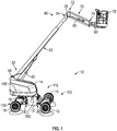
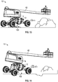
- a lift device e.g., an aerial work platform, a telehandler, a boom lift, a scissor lift, etc.
- lift device 10 includes a chassis, shown as lift base 12.
- the lift device 10 is another type of vehicle (e.g., a fire apparatus, a military vehicle, an airport rescue fire fighting ("ARFF") truck, a boom truck, a refuse vehicle, a fork lift, etc.).
- ARFF airport rescue fire fighting
- the lift base 12 supports a rotatable structure, shown as turntable 14, and a boom assembly, shown as boom 40.
- the turntable 14 is rotatable relative to the lift base 12.
- the turntable 14 includes a counterweight positioned at a rear of the turntable 14.
- the counterweight is otherwise positioned and/or at least a portion of the weight thereof is otherwise distributed throughout the lift device 10 (e.g., on the lift base 12, on a portion of the boom 40, etc.).
- a first end, shown as front end 20, of the lift base 12 is supported by a first plurality of tractive elements, shown as front tractive elements 16, and an opposing second end, shown as rear end 30, of the lift base 12 is supported by a second plurality of tractive elements, shown as rear tractive elements 18.
- the front tractive elements 16 and the rear tractive elements 18 include wheels.
- the front tractive elements 16 and/or the rear tractive elements 18 include a track element.
- the boom 40 includes a first boom section, shown as lower boom 50, and a second boom section, shown as upper boom 70.
- the boom 40 includes a different number and/or arrangement of boom sections (e.g., one, three, etc.).
- the boom 40 is an articulating boom assembly.
- the upper boom 70 is shorter in length than lower boom 50.
- the upper boom 70 is longer in length than the lower boom 50.
- the boom 40 is a telescopic, articulating boom assembly.
- the upper boom 70 and/or the lower boom 50 may include a plurality of telescoping boom sections that are configured to extend and retract along a longitudinal centerline thereof to selectively increase and decrease a length of the boom 40.
- the lower boom 50 has a first end (e.g., lower end, etc.), shown as base end 52, and an opposing second end, shown as intermediate end 54.
- the base end 52 of the lower boom 50 is pivotally coupled (e.g., pinned, etc.) to the turntable 14 at a joint, shown as lower boom pivot 56.
- the boom 40 includes a first actuator (e.g., pneumatic cylinder, electric actuator, hydraulic cylinder, etc.), shown as lower lift cylinder 60.
- the lower lift cylinder 60 has a first end coupled to the turntable 14 and an opposing second end coupled to the lower boom 50.
- the lower lift cylinder 60 is positioned to raise and lower the lower boom 50 relative to the turntable 14 about the lower boom pivot 56.
- the upper boom 70 has a first end, shown as intermediate end 72, and an opposing second end, shown as implement end 74.
- the intermediate end 72 of the upper boom 70 is pivotally coupled (e.g., pinned, etc.) to the intermediate end 54 of the lower boom 50 at a joint, shown as upper boom pivot 76.
- the boom 40 includes an implement, shown as platform assembly 92, coupled to the implement end 74 of the upper boom 70 with an extension arm, shown as jib arm 90.
- the jib arm 90 is configured to facilitate pivoting the platform assembly 92 about a lateral axis (e.g., pivot the platform assembly 92 up and down, etc.).
- the jib arm 90 is configured to facilitate pivoting the platform assembly 92 about a vertical axis (e.g., pivot the platform assembly 92 left and right, etc.). In some embodiments, the jib arm 90 is configured to facilitate extending and retracting the platform assembly 92 relative to the implement end 74 of the upper boom 70.
- the boom 40 includes a second actuator (e.g., pneumatic cylinder, electric actuator, hydraulic cylinder, etc.), shown as upper lift cylinder 80.
- the upper lift cylinder 80 is positioned to actuate (e.g., lift, rotate, elevate, etc.) the upper boom 70 and the platform assembly 92 relative to the lower boom 50 about the upper boom pivot 76.
- the platform assembly 92 is a structure that is particularly configured to support one or more workers.
- the platform assembly 92 includes an accessory or tool configured for use by a worker.
- Such tools may include pneumatic tools (e.g., impact wrench, airbrush, nail gun, ratchet, etc.), plasma cutters, welders, spotlights, etc.
- the platform assembly 92 includes a control panel to control operation of the lift device 10 (e.g., the turntable 14, the boom 40, etc.) from the platform assembly 92.
- the platform assembly 92 includes or is replaced with an accessory and/or tool (e.g., forklift forks, etc.).
- the lift device 10 includes a chassis leveling assembly, shown as leveling system 100.
- the leveling system 100 is configured to facilitate maintaining the lift base 12, the turntable 14, and/or the platform assembly 92 of the lift device 10 level relative to gravity (e.g., while stationary, while being driven on uneven and/or sloped ground, while operating the boom 40, etc.).
- the leveling system 100 includes a first leveling assembly, shown as front leveling assembly 110, pivotally coupled to the front end 20 of the lift base 12 and a second leveling assembly, shown as rear leveling assembly 120, pivotally coupled to the rear end 30 of the lift base 12.
- the front leveling assembly 110 and the rear leveling assembly 120 operate as a semi-independent suspension system for the lift device 10.
- a semi-independent suspension operation may facilitate providing two degrees of movement (e.g., pitch and roll, etc.) with each of the front leveling assembly 110 and the rear leveling assembly 120.
- the lift device 10 may provide various features and/or performance characteristics that are advantageous for lift device operation. Such advantages may include: (i) providing a platform capacity of up to 600 pounds or more, (ii) providing a platform height of up to 46.5 feet or more, (iii) providing a horizontal reach of up to 39 feet or more, (iv) providing a platform rotation of up to 180 degrees or more, (v) providing a boom swing of up to 360 degrees, (vi) providing a drive speed of up to 4.5 miles per hour or more, (vii) providing a gradeability of up to 45 degrees or more, (viii) providing a turning radius of 16 feet or less, (ix) providing a variable ground clearance between less than 6 inches to more than 22 inches, and/or (x) providing up to +/- 10 degrees or more of chassis pitch and roll, among still other advantages.
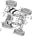
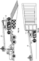
- the front leveling assembly 110 includes a first carrier arm, shown as front trailing arm 130; a first axle, shown as front axle 150; a first front actuator, shown as front right actuator 170; and a second front actuator, shown as front left actuator 180.
- the front right actuator 170 and the front left actuator 180 each include a hydraulic cylinder.
- the front right actuator 170 and/or the front left actuator 180 include another type of actuator (e.g., a pneumatic cylinder, an electric actuator, etc.).
- a pneumatic cylinder e.g., an electric actuator, etc.
- the front trailing arm 130 has a first portion, shown as base 131, positioned at a first end, shown as chassis end 132, of the front trailing arm 130.
- the front trailing arm 130 has a second portion, shown as projection 133, positioned at an opposing second end, shown as axle end 134, of the front trailing arm 130.
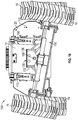
- the front trailing arm 130 has a third portion, shown as transition 135, extending between the base 131 and the projection 133. As shown in FIGS.
- the base 131 defines a pivot interface at the chassis end 132 of the front trailing arm 130 that pivotally couples to the front end 20 of the lift base 12 at a pair of pivot points positioned at a bottom end of the front end 20 of the lift base 12, shown as lower right pivot 26 and lower left pivot 28.
- a pivotal coupling between the front end 20 of the lift base 12 and the front trailing arm 130 may facilitate a pitch adjustment operation of the front leveling assembly 110 (e.g., pivoting of the front trailing arm 130 about a lateral axis extending through the lower right pivot 26 and the lower left pivot 28, etc.).
- the transition 135 extends from the base 131 to the projection 133 at an angle such that the projection 133 is elevated relative to the base 131.
- the front trailing arm 130 may thereby have a ramped or sloped profile (e.g., an elongated S-shape, an elongated Z-shape, etc.).
- the base 131 and the projection 133 are parallel with each other (e.g., planes defined by the base 131 and the projection 133 may be parallel, etc.). As shown in FIG.
- the front trailing arm 130 has a dual-plate construction such that the front trailing arm 130 includes a first, upper plate and a second, lower plate spaced from the first, upper plate (e.g., a space or gap is formed therebetween, etc.).
- the front trailing arm 130 has a single plate construction and/or has a solid structure.
- the front axle 150 has a first end, shown as right end 152, and an opposing second end, shown as left end 154.
- a first front tractive element 16 is coupled to the right end 152 of the front axle 150
- a second front tractive element 16 is coupled to the left end 154 of the front axle 150.
- the front axle 150 includes a coupler, shown as front axle pivot interface 156, positioned to engage a corresponding coupler, shown as front trailing arm pivot interface 136, defined by the projection 133 and positioned at the axle end 134 of the front trailing arm 130.
- FIG. 1 the front axle 150 includes a coupler, shown as front axle pivot interface 156, positioned to engage a corresponding coupler, shown as front trailing arm pivot interface 136, defined by the projection 133 and positioned at the axle end 134 of the front trailing arm 130.
- the front axle pivot interface 156 and the front trailing arm pivot interface 136 are configured to interengage and cooperatively receive a fastener, shown as pin 158.
- the pin 158 pivotally couples the front axle 150 to the axle end 134 of the front trailing arm 130.
- the pivotal joint between the front trailing arm 130 and the front axle 150 may facilitate a roll adjustment operation of the front leveling assembly 110 about the pin 158 (e.g., pivoting of the front axle 150 about a central longitudinal axis of the lift device 10, etc.).
- a first end (e.g., an upper end, etc.) of the front right actuator 170 is pivotally coupled to the front end 20 of the lift base 12 at a pivot point, shown as upper right pivot 22.
- an opposing second end (e.g., a lower end, etc.) of the front right actuator 170 is pivotally coupled to a corresponding pivot point positioned along the front axle 150 (e.g., proximate the right end 152 thereof, etc.).
- a first end (e.g., an upper end, etc.) of the front left actuator 180 is pivotally coupled to the front end 20 of the lift base 12 at a pivot point, shown as upper left pivot 24.
- an opposing second end (e.g., a lower end, etc.) of the front left actuator 180 is pivotally coupled to a corresponding pivot point positioned along the front axle 150 (e.g., proximate the left end 154 thereof, etc.).
- Such a pivotal coupling of (i) the front right actuator 170 between the front end 20 of the lift base 12 and the front axle 150 and (ii) the front left actuator 180 between the front end 20 of the lift base 12 and the front axle 150 may facilitate actively and/or passively providing the pitch and/or roll adjustment operations of the front leveling assembly 110 (e.g., pivoting of the front trailing arm 130 about a lateral axis extending through the lower right pivot 26 and the lower left pivot 28, pivoting of the front axle 150 about a central longitudinal axis of the lift device 10, etc.).
- the front leveling assembly 110 e.g., pivoting of the front trailing arm 130 about a lateral axis extending through the lower right pivot 26 and the lower left pivot 28, pivoting of the front axle 150 about a central longitudinal axis of the lift device 10, etc.
- the rear leveling assembly 120 includes a second carrier arm, shown as rear trailing arm 140; a second axle, shown as rear axle 160; a first rear actuator, shown as rear right actuator 190; and a second rear actuator, shown as rear left actuator 200.
- the rear right actuator 190 and the rear left actuator 200 each include a hydraulic cylinder.
- the rear right actuator 190 and/or the rear left actuator 200 include another type of actuator (e.g., a pneumatic cylinder, an electric actuator, etc.). As shown in FIGS.
- the rear trailing arm 140 has a first portion, shown as base 141, positioned at a first end, shown as chassis end 142, of the rear trailing arm 140. As shown in FIGS. 2-4 , 8 , and 9 , the rear trailing arm 140 has a second portion, shown as projection 143, positioned at an opposing second end, shown as axle end 144, of the rear trailing arm 140. As shown in FIGS. 2 and 3 , the rear trailing arm 140 has a third portion, shown as transition 145, extending between the base 141 and the projection 143.
- the base 141 defines a pivot interface at the chassis end 142 of the rear trailing arm 140 that pivotally couples to the rear end 30 of the lift base 12 at a pair of lower pivot points positioned at a bottom end of the rear end 30 of the lift base 12 (e.g., similar to the base 131 of the front trailing arm 130 at the lower right pivot 26 and the lower left pivot 28, etc.).
- a pivotal coupling between the rear end 30 of the lift base 12 and the rear trailing arm 140 may facilitate a pitch adjustment operation of the rear leveling assembly 120 (e.g., pivoting of the rear trailing arm 140 about a lateral axis extending through the pair of lower pivot points of the rear end 30 of the lift base 12, etc.).
- the transition 145 extends from the base 141 to the projection 143 at an angle such that the projection 143 is elevated relative to the base 141.
- the rear trailing arm 140 may thereby have a ramped or sloped profile (e.g., an elongated S-shape, an elongated Z-shape, etc.).
- the base 141 and the projection 143 are parallel with each other (e.g., planes defined by the base 141 and the projection 143 may be parallel, etc.).
- the rear trailing arm 140 has a dual-plate construction such that the rear trailing arm 140 includes a first, upper plate and a second, lower plate spaced from the first, upper plate (e.g., a space or gap is formed therebetween, etc.).
- the rear trailing arm 140 has a single plate construction and/or has a solid structure.
- the rear axle 160 has a first end, shown as right end 162, and an opposing second end, shown as left end 164.
- a first rear tractive element 18 is coupled to the right end 162 of the rear axle 160 and a second rear tractive element 18 is coupled to the left end 164 of the rear axle 160.
- the rear axle 160 includes a rear axle pivot interface (e.g., similar to the front axle pivot interface 156 of the front axle 150, etc.) positioned to engage a corresponding rear trailing arm pivot interface defined by the projection 143 and positioned at the axle end 144 of the rear trailing arm 140 (e.g., similar to the front trailing arm pivot interface 136 of the front trailing arm 130, etc.).
- the rear axle pivot interface and the rear trailing arm pivot interface are configured to interengage and cooperatively receive a fastener (e.g., similar to the pin 158, etc.) to pivotally couple the rear axle 160 to the rear trailing arm 140, according to an exemplary embodiment.
- the pivotal joint between the rear trailing arm 140 and the rear axle 160 may facilitate a roll adjustment operation of the rear leveling assembly 120 (e.g., pivoting of the rear axle 160 about a central longitudinal axis of the lift device 10, etc.).
- a first end (e.g., an upper end, etc.) of the rear right actuator 190 is pivotally coupled to the rear end 30 of the lift base 12 at a pivot point, shown as upper right pivot 32.
- an opposing second end (e.g., a lower end, etc.) of the rear right actuator 190 is pivotally coupled to a corresponding pivot point positioned along the rear axle 160 (e.g., proximate the right end 162 thereof, etc.).
- a first end (e.g., an upper end, etc.) of the rear left actuator 200 is pivotally coupled to the rear end 30 of the lift base 12 at a pivot point, shown as upper left pivot 34.
- an opposing second end (e.g., a lower end, etc.) of the rear left actuator 200 is pivotally coupled to a corresponding pivot point positioned along the rear axle 160 (e.g., proximate the left end 164 thereof, etc.).
- Such a pivotal coupling of (i) the rear right actuator 190 between the rear end 30 of the lift base 12 and the rear axle 160 and (ii) the rear left actuator 200 between the rear end 30 of the lift base 12 and the rear axle 160 may facilitate actively and/or passively providing the pitch and/or roll adjustment operations of the rear leveling assembly 120 (e.g., pivoting of the rear trailing arm 140 about a lateral axis extending through the pair of lower pivot points of the rear end 30 of the lift base 12, pivoting of the rear axle 160 about a central longitudinal axis of the lift device 10, etc.).
- the front axle 150 and the rear axle 160 include a drive system, shown as drive system 220.
- the drive system 220 includes actuators (e.g., pneumatic cylinders, electric actuators, hydraulic cylinders, etc.), shown as steering actuators 222, and drivers (e.g., electric actuators, motors, etc.), shown as drive actuators 224.
- the front axle 150 includes a pair of steering actuators 222. Each steering actuator 222 may be positioned to facilitate steering one of the front tractive elements 16 (e.g., independent steering of each of the front tractive elements 16, etc.).
- the rear axle 160 includes a pair of steering actuators 222.
- Each steering actuator 222 may be positioned to facilitate steering one of the rear tractive elements 18 (e.g., independent steering of each of the rear tractive elements 18, etc.).
- the front axle 150 and/or the rear axle 160 include a single steering actuator 222 positioned to facilitate steering both of the front tractive elements 16 and/or both of the rear tractive elements 18, respectively.
- the front axle 150 includes a pair of drive actuators 224.
- Each drive actuator 224 may be positioned to facilitate driving one of the front tractive elements 16.
- the rear axle 160 includes a pair of drive actuators 224.
- Each drive actuator 224 may be positioned to facilitate driving one of the rear tractive elements 18.
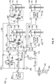
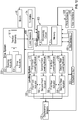
- the lift device 10 includes an actuator circuit, shown as actuator circuit 300, and a control system, shown as lift device control system 400.
- the actuator circuit 300 includes a hydraulic circuit configured to facilitate operating (e.g., driving the extension and/or retraction of, etc.) the front right actuator 170, the front left actuator 180, the rear right actuator 190, the rear left actuator 200, the steering actuators 222, and/or the drive actuators 224 (e.g., in embodiments where the actuators include hydraulic cylinders, etc.).
- the actuator circuit 300 includes an electric circuit (e.g., in embodiments where the actuators include electric actuators, etc.) and/or a pneumatic circuit (e.g., in embodiment where the actuators include pneumatic cylinders, etc.).
- the lift device control system 400 is configured to control the operation of the actuator circuit 300 and thereby the front right actuator 170, the front left actuator 180, the rear right actuator 190, the rear left actuator 200, the steering actuators 222, and/or the drive actuators 224 (e.g., the extension and/or retraction thereof, the relative motion between the front axle 150 and/or the rear axle 160 and the lift base 12, the pitch and/or roll adjustment operations of the front axle 150 and/or the rear axle 160, etc.).
- the actuator circuit 300 and thereby the front right actuator 170, the front left actuator 180, the rear right actuator 190, the rear left actuator 200, the steering actuators 222, and/or the drive actuators 224 (e.g., the extension and/or retraction thereof, the relative motion between the front axle 150 and/or the rear axle 160 and the lift base 12, the pitch and/or roll adjustment operations of the front axle 150 and/or the rear axle 160, etc.).
- the actuator circuit 300 includes a pump, shown as pump 302, a fluid reservoir, shown as tank 304, and a low pressure source, shown as low pressure source 306.
- the tank 304 is configured to supply the pump 302 with a fluid (e.g., hydraulic fluid, compressed air, etc.), which the pump 302 provides at a high pressure throughout the actuator circuit 300.
- the actuator circuit 300 includes a high pressure line, shown as high pressure line 310, that includes a first high pressure line, shown as front high pressure line 320, and a second high pressure line, shown as rear high pressure line 330.
- the front high pressure line 320 includes a first front high pressure line, shown as front right high pressure line 322, and a second front high pressure line, shown as front left high pressure line 324.
- the front right high pressure line 322 fluidly couples the pump 302 to a first front leveling module, shown as front right leveling module 172, associated with the front right actuator 170 and configured to facilitate an extension and retraction operation of the front right actuator 170.
- the front left high pressure line 324 fluidly couples the pump 302 to a second front leveling module, shown as front left leveling module 182, associated with the front left actuator 180 and configured to facilitate an extension and retraction operation of the front left actuator 180.
- the rear high pressure line 330 includes a first rear high pressure line, shown as rear right high pressure line 332, and a second rear high pressure line, shown as rear left high pressure line 334.
- the rear right high pressure line 332 fluidly couples the pump 302 to a first rear leveling module, shown as rear right leveling module 192, associated with the rear right actuator 190 and configured to facilitate an extension and retraction operation of the rear right actuator 190.
- the rear left high pressure line 334 fluidly couples the pump 302 to a second rear leveling module, shown as rear left leveling module 202, associated with the rear left actuator 200 and configured to facilitate an extension and retraction operation of the rear left actuator 200.
- the high pressure line 310 is positioned to facilitate providing high pressure fluid to a first chamber, shown as first chamber 174, first chamber 184, first chamber 194, and first chamber 204, of the front right actuator 170, the front left actuator 180, the rear right actuator 190, and the rear left actuator 200, respectively, to facilitate an extension operation thereof.
- the actuator circuit 300 includes a low pressure line including a first low pressure line, shown as front low pressure line 340, and a second low pressure line, shown as rear low pressure line 350.
- the front low pressure line 340 includes a first front low pressure line, shown as front right low pressure line 342, and a second front low pressure line, shown as front left low pressure line 344.
- the front right low pressure line 342 and the front left low pressure line 344 are fluidly coupled to a third low pressure line, shown as third low pressure line 346.
- the third low pressure line 346 fluidly couples the front right leveling module 172 and the front left leveling module 182 to a valve block, shown as valve block 370.
- the valve block 370 includes a valve, shown as valve 376, positioned to selectively fluidly couple the front low pressure line 340 to the low pressure source 306 and/or a reservoir, shown as tank 308 (e.g., based on a mode of operation of the lift device 10, etc.).
- the rear low pressure line 350 includes a first rear low pressure line, shown as rear right low pressure line 352, and a second rear low pressure line, shown as rear left low pressure line 354.
- the rear right low pressure line 352 and the rear left low pressure line 354 are fluidly coupled to a third low pressure line, shown as third low pressure line 356.
- the third low pressure line 356 fluidly couples the rear right leveling module 192 and the rear left leveling module 202 to the tank 308.
- the front low pressure line 340 is positioned to facilitate providing low pressure fluid to a second chamber, shown as second chamber 176 and second chamber 186, of the front right actuator 170 and the front left actuator 180, respectively, to facilitate a retraction operation thereof.
- rear low pressure line 350 is positioned to facilitate providing low pressure fluid to a second chamber, show as second chamber 196 and second chamber 206, of the rear right actuator 190 and the rear left actuator 200, respectively, to facilitate a retraction operation thereof.
- the actuator circuit 300 includes an auxiliary line, shown as auxiliary line 360.
- the auxiliary line 360 includes a first auxiliary line, shown as front right auxiliary line 362, and a second auxiliary line, shown as front left auxiliary line 364.
- the front right auxiliary line 362 and the front left auxiliary line 364 are fluidly coupled to a third auxiliary line, shown as third auxiliary line 366.
- the third auxiliary line 366 fluidly couples the front right leveling module 172 and the front left leveling module 182 to the valve block 370.
- the front low pressure line 340, the auxiliary line 360, and/or the valve block 370 are cooperatively engaged to operate the front right actuator 170 and the front left actuator 180 according to a passive mode of operation (e.g., based on the mode of operation of the lift device 10, a front leveling assembly free oscillation mode, etc.).
- a passive mode of operation e.g., based on the mode of operation of the lift device 10, a front leveling assembly free oscillation mode, etc.
- the passive mode of operation may be facilitated by activating (e.g., energizing, switching, opening, closing, etc.) valves (e.g., proportional valves, load holding valves, electro-magnetic valves, etc.) of the valve block 370, shown as valve 372 and valve 374.
- Such activation may include opening or closing one or more valves of the front right leveling module 172, shown as actuator valves 178, and the front left leveling module 182, shown as actuator valves 188.
- Such an operation may additionally or alternatively include activating (e.g., energizing, switching, opening, closing, etc.) a valve of the valve block 370, shown as valve 376, a valve of the front right leveling module 172, shown as actuator valve 179, and/or a valve of the front left leveling module 182, shown as actuator valve 189.
- Such activation may thereby fluidly couple the first chamber 174 and/or the second chamber 176 of the front right actuator 170 to the first chamber 184 and/or the second chamber 186 of the front left actuator 180 to facilitate a fluid flow (e.g., a free fluid flow, etc.) therebetween (e.g., between the first chamber 174 and the second chamber 186, between the second chamber 176 and the first chamber 184, etc.), as well as isolate the front right actuator 170 and the front left actuator 180 from the pump 302 (e.g., the front right actuator 170 and the front left actuator 180 do not receive high pressure fluid from the pump 302 such that they are not actively controlled, but passively controlled, etc.).
- the pressure from the low pressure source 306 is configured to ensure that the front low pressure line 340 remains pressurized (e.g., account for losses, etc.) through a valve, shown as check valve 378.
- the lift device control system 400 for the lift device 10 includes a controller 410.
- the controller 410 is configured to selectively engage, selectively disengage, control, and/or otherwise communicate with components of the lift device 10 (e.g., actively control the components thereof, etc.).
- the controller 410 is configured to facilitate passively controlling at least some of the components to the lift device 10 (e.g., based on the mode of operation of the lift device 10, the front leveling assembly 110, etc.). As shown in FIG.
- the controller 410 is coupled to the turntable 14, the boom 40, the leveling system 100 (e.g., the leveling modules thereof, etc.), the drive system 220 (e.g., the steering actuators 222, the drive actuators 224, etc.), the actuator circuit 300, various sensors including displacement sensors 402, roll sensors 404, pitch sensors 406, and load sensors 408, and a user interface 440.
- the controller 410 is coupled to more or fewer components.
- the controller 410 may be configured to actively control the pitch adjustment and/or the roll adjustment of at least the one of (i) the front leveling assembly 110 (e.g., through the extension and/or retraction of the front right actuator 170 and/or the front left actuator 180, etc.) and (ii) the rear leveling assembly 120 (e.g., through the extension and/or retraction of the rear right actuator 190 and/or the rear left actuator 200, etc.) to at least improve the orientation of the lift base 12, the turntable 14, and/or the boom 40 relative to gravity (e.g., while driving the lift device 10, while operating the boom 40, in a longitudinal direction, in lateral direction, etc.).
- the front leveling assembly 110 e.g., through the extension and/or retraction of the front right actuator 170 and/or the front left actuator 180, etc.
- the rear leveling assembly 120 e.g., through the extension and/or retraction of the rear right actuator 190 and/or the rear left actuator 200, etc.
- the controller 410 may maintain the lift base 12, the turntable 14 and/or the boom 40 level relative to gravity. Such control of the front leveling assembly 110 and/or the rear leveling assembly 120 may be based on a mode of operation of the lift device 10.
- the controller 410 may send and receive signals with the turntable 14, the boom 40, the leveling system 100, the drive system 220, the actuator circuit 300, the displacement sensors 402, the roll sensors 404, the pitch sensors 406, the load sensors 408, and/or the user interface 440.
- the controller 410 may be implemented as a general-purpose processor, an application specific integrated circuit (ASIC), one or more field programmable gate arrays (FPGAs), a digital-signal-processor (DSP), circuits containing one or more processing components, circuitry for supporting a microprocessor, a group of processing components, or other suitable electronic processing components.
- the controller 410 includes a processing circuit 412 and a memory 414.
- the processing circuit 412 may include an ASIC, one or more FPGAs, a DSP, circuits containing one or more processing components, circuitry for supporting a microprocessor, a group of processing components, or other suitable electronic processing components.
- the processing circuit 412 is configured to execute computer code stored in the memory 414 to facilitate the activities described herein.
- the memory 414 may be any volatile or non-volatile computer-readable storage medium capable of storing data or computer code relating to the activities described herein.
- the memory 414 includes computer code modules (e.g., executable code, object code, source code, script code, machine code, etc.) configured for execution by the processing circuit 412.
- the memory 414 includes various actuation profiles corresponding to loading conditions experienced by the leveling system 100 and/or corresponding to modes of operation of the lift device 10, according to an exemplary embodiment.
- controller 410 represents a collection of processing devices (e.g., servers, data centers, etc.). In such cases, the processing circuit 412 represents the collective processors of the devices, and the memory 414 represents the collective storage devices of the devices.
- the user interface 440 includes a display and an operator input.
- the display may be configured to display a graphical user interface, an image, an icon, and/or still other information.
- the display includes a graphical user interface configured to provide general information about the left device (e.g., vehicle speed, fuel level, warning lights, battery level, etc.).
- the graphical user interface may also be configured to display a current position of the leveling system 100, a current position of the boom 40, a current position of the turntable 14, an orientation of the lift base 12 (e.g., angle relative to a ground surface, etc.), and/or still other information relating to the lift device 10 and/or the leveling system 100.
- the operator input may be used by an operator to provide commands to at least one of the turntable 14, the boom 40, the leveling system 100, the drive system 220, and the actuator circuit 300.
- the operator input may include one or more buttons, knobs, touchscreens, switches, levers, joysticks, pedals, a steering wheel, or handles.
- the operator input may facilitate manual control of some or all aspects of the operation of the lift device 10. It should be understood that any type of display or input controls may be implemented with the systems and methods described herein.
- the controller 410 is configured to send and receive displacement data from the displacement sensors 402, roll data from the roll sensors 404, pitch data from the pitch sensors 406, and/or load data from the load sensors 408.
- the displacement sensors 402 may be positioned to acquire the displacement data regarding the front right actuator 170, the front left actuator 180, the rear right actuator 190, and/or the rear left actuator 200.
- the displacement data may be indicative of an amount of displacement and/or a position (e.g., extension, retraction, etc.) of the front right actuator 170, the front left actuator 180, the rear right actuator 190, and/or the rear left actuator 200 (e.g., relative to a neutral position, a nominal position, etc.).
- the roll sensors 404 may be positioned to acquire the roll data regarding the front leveling assembly 110, the rear leveling assembly 120, the front axle 150, and/or the rear axle 160.
- the roll data may be indicative of a roll angle and/or a rate of change of the roll angle of the front axle 150 about the pin 158 and/or the rear axle 160 about the corresponding pin thereof (e.g., relative to a horizontal roll alignment, a zero roll angle, etc.).
- the pitch sensors 406 may be positioned to acquire the pitch data regarding the front leveling assembly 110, the rear leveling assembly 120, the front axle 150, and/or the rear axle 160.
- the pitch data may be indicative of a pitch angle and/or a rate of change of the pitch angle of the front axle 150 about the coupling between the chassis end 132 of the front trailing arm 130 and the front end 20 of the lift base 12 and/or the rear axle 160 about the coupling between the chassis end 142 of the rear trailing arm 140 and the rear end 30 of the lift base 12 (e.g., relative to a horizontal pitch alignment, a zero pitch angle, etc.).
- the load sensors 408 may be positioned to acquire the load data regarding the front tractive elements 16 and/or the rear tractive elements 18.
- the load data may be indicative of a loading experienced by each of the front tractive elements 16 and/or each of the rear tractive elements 18.
- the controller 410 monitors the leveling status, the ground following status, and/or the height of the lift base 12 of the lift device 10 using the displacement data, the roll data, the pitch data, and/or the load data.
- the controller 410 is configured to facilitate operating the lift device in various modes of operation.
- the modes of operation of the lift device may include a transportation or stowed mode, a driving mode, a boom operation mode, and/or a calibration mode.
- the various modes of operation may be selected by an operator of the lift device 10 and/or automatically activated by the controller 410 based on the current operation of the lift device 10 (e.g., driving, operating the turntable 14, operating the boom 40, etc.).
- the controller 410 may actively control at least one of the front leveling assembly 110 and the rear leveling assembly 120 based on the mode of operation of the lift device 10.
- the controller 410 is configured to control operation of the front right actuator 170, the front left actuator 180, the rear right actuator 190, and/or the rear left actuator 200 based on at least one of the displacement data, the roll data, the pitch data, the load data, the mode of operation of the lift device 10, the operation of the turntable 14, and/or the operation of the boom 40.
- the controller 410 is configured to provide a command to the leveling system 100 (e.g., the leveling modules 172, 182, 192, and 202, etc.) to reduce the overall height of the lift base 12 to a target height (e.g., a minimum height, a stowed height, a shipping height, etc.) in response to the lift device 10 being switched into the transportation or stowed mode (e.g., to provide a squatting capability, etc.).
- a target height e.g., a minimum height, a stowed height, a shipping height, etc.
- Such a reduction in the overall height of the lift device 10 may facilitate storing the lift device within an ISO container (e.g., containerization, etc.) and/or provide greater stability and clearance during transportation (e.g., by lowering the center of gravity thereof, etc.).
- the controller 410 is configured to limit the speed of the lift device 10 and/or the operation of the turntable 14 and/or the boom 40 during the
- the controller 410 is configured to provide a command to the leveling system 100 to calibrate the displacement sensors 402, the roll sensors 404, the pitch sensors 406, and/or the load sensors 408 when the lift device 10 is in the calibration mode.
- the calibration mode may be activated each time the lift device 10 is turned on, on a periodic basis, in response to an operator command, and/or in response to the various data indicating potential miscalibration.
- the calibration mode may include the leveling system 100, the turntable 14, and/or the boom 40 returning to a nominal position (e.g., fully extended, fully retracted, etc.) such that the sensors may be zeroed out.
- the controller 410 is configured to actively control the rear leveling assembly 120 (e.g., based on the pitch data, the roll data, the displacement data, and/or the load data, etc.) and passively control the front leveling assembly 110 (e.g., as depicted in FIG. 11 , etc.) in response to the lift device 10 being operated in the driving mode.
- the front leveling assembly 110 is actively controlled, while the rear leveling assembly 120 is passively controlled when the lift device 10 is in the driving mode.
- the passive control of the front leveling assembly 110 may allow the front axle 150 to freely float and/or oscillate as the front tractive elements 16 encounter various terrain (e.g., slopes, pot holes, rocks, etc.) with the front right actuator 170 and the front left actuator 180 fluidly coupled (e.g., by the front low pressure line 340 and the auxiliary line 360, etc.).
- the front axle 150 is allowed to freely float in the roll direction.
- the front axle 150 is allowed to freely float in the roll direction and/or the pitch direction.
- the active control of the rear leveling assembly 120 e.g., the rear right actuator 190, the rear left actuator 200, etc.
- operation of the turntable 14 and/or the boom 40 are limited and/or disabled by the controller 410 during the driving mode.
- limiting the use of the turntable 14 and/or the boom 40 may maintain a lower center of gravity of the lift device 10 such that the lift device 10 may operate at higher speeds with improved stability.
- the controller 410 actively controlling of the rear leveling assembly 120 and passively controlling the front leveling assembly 110 provides a smooth ground following capability and increased terrainability (e.g., terrain negotiation, etc.).
- the actuator circuit 300 may also require less power (e.g., requires less hydraulic flow from the pump 302, since only the two rear actuators are actively controlled, compared to actively controlling all four actuators, etc.) during the driving mode of the lift device 10.
- the controller 410 is configured to actively control the front leveling assembly 110 and the rear leveling assembly 120 in response to the lift device 10 being operated in the boom operation mode (e.g., the turntable 14 and/or the boom 40 being operated, etc.).
- the active control of the rear leveling assembly 120 e.g., the rear right actuator 190, the rear left actuator 200, etc.
- the front leveling assembly 110 e.g., the front right actuator 170, the front left actuator 180, etc.
- the controller 410 limits the speed of the lift device 10 during the boom operation mode.
- operating the turntable 14 and/or the boom 40 may raise the center of gravity of the lift device 10 such that limiting the speed to lower operating speeds may facilitate increased stability.
- the controller 410 is configured to control operation of the front right actuator 170, the front left actuator 180, the rear right actuator 190, and the rear left actuator 200 based on at least one of the displacement data, the roll data, the pitch data, the load data, the position of the turntable 14, and/or the position of the boom 40 (e.g., the platform assembly 92, etc.) while the lift device 10 is in the boom operation mode.
- the boom operation mode may be used while the lift device 10 is stationary and/or moving (e.g., at a reduced speed, a governed speed, a creep speed, etc.).
- the various data may be used to maintain the lift base 12 level relative to gravity and/or maintain the front tractive elements 16 and the rear tractive elements 18 in contact with the ground as the center of gravity of the lift device 10 varies while in the boom operation mode (e.g., as the platform assembly 92 is selectively raised, lowered, extended, retracted, etc.).
- the lift device 10 is configured to operate (e.g., as controlled by the controller 410, etc.) in various modes (e.g., to negotiate various terrain or obstacles, facilitate transportation, etc.).
- the leveling system 100 of the lift device 10 is configured to increase the terrainability by increasing the capabilities of the lift device 10 to negotiate obstacles (e.g., pot holes, bumps, rocks, etc.), while maintaining the lift base 12, the turntable 14, and the boom 40 level relative to gravity (e.g., while operating in the driving mode, the boom operation mode, etc.).
- obstacles e.g., pot holes, bumps, rocks, etc.
- the leveling system 100 may additionally improve traction capabilities of the lift device 10 by distributing loads throughout the rear tractive elements 18 and/or the front tractive elements 16 while on and/or driving along uneven and/or sloped terrain.
- the leveling system 100 is configured to facilitate negotiation of and self-leveling on inclines or slopes, while maintaining the lift base 12, the turntable 14, and the boom 40 level relative to gravity (e.g., while operating in the driving mode, the boom operation mode, etc.).
- Such self-leveling may ease the loading of the lift device 10 onto a truck bed and/or increase the stability of the lift device 10 during operation of the boom 40 and/or the turntable 14 while on an incline or slope.
- the leveling system 100 is configured to facilitate a squatting capability such that the height of the lift base 12 is reduced.
- the squatting capability may provide greater stability and clearance while the lift device 10 is transported (e.g., via a truck, etc.) and/or facilitate containerization of the lift device 10 for shipping (e.g., by reducing the overall height of the lift device 10 such that the lift device 10 fits within an ISO container, etc.).
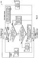
- the lift device 10 is powered on (e.g., in response to receiving a power on command from an operator, etc.).
- the controller 410 determines a mode of operation of the lift device 10 (e.g., transportation mode, calibration mode, driving mode, boom operation mode, etc.).
- the mode of operation may be manually operator selected, automatically initiated at power on, automatically initiated at power off, and/or automatically initiated in response to an operator input to drive the lift device 10, operate the turntable 14, and/or operate the boom 40.
- the controller 410 is configured to provide a command to the leveling system 100 to adjust the height of the lift base 12 to a target height (e.g., a transportation height, a stowed height, etc.) in response to the initiation of a transport mode of operation.
- the transport mode of operation may be initiated in response to an operator selection and/or in response to the lift device 10 being powered off.
- the controller 410 is configured to limit the speed of the lift device 10 and/or the operation of the turntable 14 and/or the boom 40 during the transportation mode of operation.
- the controller 410 is configured to provide a command to the leveling system 100 to run a sensor calibration algorithm to facilitate calibrating one or more sensors of the lift device 10 (e.g., the displacement sensors 402, the roll sensors 404, the pitch sensors 406, the load sensors 408, etc.) in response to the initiation of a calibration mode of operation.
- the calibration mode of operation may be initiated each time the lift device 10 is turned on, on a periodic basis, in response to an operator command, and/or in response to the various data indicating potential miscalibration.
- the sensor calibration algorithm may include the leveling system 100, the turntable 14, and/or the boom 40 returning to a nominal position (e.g., fully extended, fully retracted, etc.) such that the sensors may be zeroed out.
- the controller 410 is configured to actively control a first leveling assembly (e.g., the rear leveling assembly 120, etc.) and passively control a second leveling assembly (e.g., the front leveling assembly 110, etc.) of the leveling system 100 in response to initiation of the driving mode of operation.
- the driving mode may be initiated in response to an operator providing a command to drive the lift device 10 while the boom 40 is in a stowed position and/or a boom operation mode.
- the controller 410 is configured to control the first leveling assembly based on data (e.g., pitch data, roll data, the displacement data, the load data, etc.) received from the one or more sensors (e.g., the displacement sensors 402, the roll sensors 404, the pitch sensors 406, the load sensors 408, etc.).
- the controller 410 is configured to limit and/or disable operation of the turntable 14 and/or the boom 40 while the lift device 10 is in the driving mode.
- the controller 410 is configured to determine a compound tilt angle (e.g., a combination of the roll angle and the pitch angle, etc.) of the lift device 10 and compare the compound tilt angle to a first tilt angle threshold in response to the initiation of a boom operation mode.
- the boom operation mode may be initiated in response to an operator providing a command to operate the turntable 14 and/or the boom 40 of the lift device 10.
- the first tilt angle threshold is five degrees. In other embodiments, the first tilt angle threshold is less than or greater than five degrees (e.g., four degrees, six degrees, seven degrees, etc.).
- the controller 410 is configured to disable the leveling function, disable the drive function, and/or limit boom function (step 542). If the compound tilt angle is less than the first tilt angle threshold, the controller 410 is configured to compare the compound tilt angle to a second tilt angle threshold (step 544).
- the second tilt angle threshold is three degrees. In other embodiments, the second tilt angle threshold is less than or greater than three degrees (e.g., four degrees, two degrees, five degrees, etc.).
- the controller 410 is configured to limit drive function (e.g., to a creep speed, a reduced speed, etc.) and/or limit boom function (step 546). If the compound tilt angle is less than the second tilt angle threshold, the controller 410 is configured to provide a command to actively control the first leveling assembly (e.g., the rear leveling assembly 120, etc.) and the second leveling assembly (e.g., the front leveling assembly 110, etc.) of the leveling system 100 (step 548).
- first leveling assembly e.g., the rear leveling assembly 120, etc.
- the second leveling assembly e.g., the front leveling assembly 110, etc.
- the controller 410 is configured to control the first leveling assembly and the second leveling assembly based on (i) data (e.g., pitch data, roll data, load data, displacement data etc.) received from the one or more sensors (e.g., the displacement sensors 402, the roll sensors 404, the pitch sensors 406, the load sensors 408, etc.), (ii) the operation of the boom 40 (e.g., the position of the platform assembly 92 relative to the lift base 12, etc.), and/or (iii) the operation of the turntable 14 (e.g., rotation thereof, etc.).
- the controller 410 is configured to power off the lift device 10 (e.g., in response to receiving a power off command from an operator, etc.).
- the method 500 is concluded until a subsequent power on command is received (step 502).
- Coupled means the joining of two members directly or indirectly to one another. Such joining may be stationary (e.g., permanent) or moveable (e.g., removable, releasable, etc.). Such joining may be achieved with the two members or the two members and any additional intermediate members being integrally formed as a single unitary body with one another or with the two members or the two members and any additional intermediate members being attached to one another.
- the term "or” is used in its inclusive sense (and not in its exclusive sense) so that when used, for example, to connect a list of elements, the term “or” means one, some, or all of the elements in the list.
- Conjunctive language such as the phrase "at least one of X, Y, and Z," unless specifically stated otherwise, is otherwise understood with the context as used in general to convey that an item, term, etc. may be either X, Y, Z, X and Y, X and Z, Y and Z, or X, Y, and Z (i.e., any combination of X, Y, and Z).
- Conjunctive language is not generally intended to imply that certain embodiments require at least one of X, at least one of Y, and at least one of Z to each be present, unless otherwise indicated.
Landscapes
- Engineering & Computer Science (AREA)
- Structural Engineering (AREA)
- Mechanical Engineering (AREA)
- Life Sciences & Earth Sciences (AREA)
- Geology (AREA)
- Transportation (AREA)
- Civil Engineering (AREA)
- Architecture (AREA)
- Mining & Mineral Resources (AREA)
- General Engineering & Computer Science (AREA)
- Soil Working Implements (AREA)
- Operation Control Of Excavators (AREA)
- Forklifts And Lifting Vehicles (AREA)
- Vehicle Body Suspensions (AREA)
- Catching Or Destruction (AREA)
- Lifting Devices For Agricultural Implements (AREA)
Claims (18)
- Dispositif de levage (10), comprenant :un châssis (12) ayant une extrémité avant (20) et une extrémité arrière (30) ; etun ensemble de mise à niveau avant (110), l'ensemble de mise à niveau avant (110) comprenant :un bras porteur avant (130) couplé de manière pivotante à l'extrémité avant (20) du châssis (12) pour faciliter un réglage de tangage avant de l'ensemble de mise à niveau avant (110) ;un essieu avant (150) couplé de manière pivotante au bras porteur avant (130) pour faciliter un réglage de roulis avant de l'ensemble de mise à niveau avant (110), l'essieu avant (150) ayant une première extrémité latérale (132) et une seconde extrémité latérale opposée (134) ;un premier actionneur avant (170) couplé de manière pivotante à l'extrémité avant (20) du châssis (12) et à la première extrémité latérale (132) de l'essieu avant (150) ; etun deuxième actionneur avant (180) couplé de manière pivotante à l'extrémité avant (20) du châssis (12) et à la seconde extrémité latérale opposée (134) de l'essieu avant (150) ;le dispositif de levage étant caractérisé en ce qu'il comprend en outre :une flèche (40) couplée de manière pivotante au châssis (12) ; etun ensemble de mise à niveau arrière (120), l'ensemble de mise à niveau arrière (120) comprenant :un bras porteur arrière (140) couplé de manière pivotante à l'extrémité arrière (30) du châssis (12) pour faciliter un réglage de tangage arrière de l'ensemble de mise à niveau arrière (120) ;un essieu arrière (160) couplé de manière pivotante au bras porteur arrière (140) pour faciliter un réglage de roulis arrière de l'ensemble de mise à niveau arrière (120), l'essieu arrière (160) ayant une première extrémité latérale (142) et une seconde extrémité latérale opposée (144) ;un premier actionneur arrière (190) couplé de manière pivotante à l'extrémité arrière (30) du châssis (12) et à la première extrémité latérale (142) de l'essieu arrière (160) ; etun deuxième actionneur arrière (200) couplé de manière pivotante à l'extrémité arrière (30) du châssis (12) et à la seconde extrémité latérale opposée (144) de l'essieu arrière (160),dans lequel le premier actionneur avant (170) et le deuxième actionneur avant (180) sont conçus pour être couplés sélectivement de manière fluidique afin de faciliter la fourniture d'une commande passive et pour être découplés sélectivement de manière fluidique afin de faciliter la fourniture d'une commande active du réglage du tangage avant et du réglage du roulis avant en fonction d'un mode de fonctionnement du dispositif de levage (10), etdans lequel le premier actionneur arrière (190) et le deuxième actionneur arrière (200) facilitent la fourniture d'une commande active du réglage du tangage arrière et du réglage du roulis arrière.
- Dispositif de levage (10) selon la revendication 1, dans lequel le bras porteur avant (130) définit une interface de pivotement de bras porteur avant (136) et l'essieu avant (150) définit une interface de pivotement d'essieu avant (156) positionnée pour venir en prise avec l'interface de pivotement de bras porteur avant (136), l'interface de pivotement de bras porteur avant (136) et l'interface de pivotement d'essieu avant (156) étant conçues pour recevoir de manière coopérative un dispositif de fixation (158) afin de coupler de manière pivotante l'essieu avant (150) au bras porteur avant (130).
- Dispositif de levage (10) selon la revendication 2, dans lequel le bras porteur arrière (140) définit une interface de pivotement de bras porteur arrière et l'essieu arrière (160) définit une interface de pivotement d'essieu arrière positionnée pour venir en prise avec l'interface de pivotement de bras porteur arrière, l'interface de pivotement de bras porteur arrière et l'interface de pivotement d'essieu arrière étant conçues pour recevoir de manière coopérative un second dispositif de fixation afin de coupler de manière pivotante l'essieu arrière (160) au bras porteur arrière (140).
- Dispositif de levage (10) selon la revendication 2, dans lequel le bras porteur avant (130) comporte :une base (131) définissant une interface de pivotement de châssis qui couple de manière pivotante le bras porteur avant (130) à une extrémité inférieure de l'extrémité avant (20) du châssis (12) ;une saillie (133) définissant l'interface de pivotement de bras porteur avant (136) qui reçoit de manière pivotante l'interface de pivotement d'essieu avant (156) ; etune transition (135) s'étendant entre la base (131) et la saillie (133) à un angle tel que la saillie (133) est en hauteur par rapport à la base (131).
- Dispositif de levage (10) selon la revendication 1, dans lequel l'ensemble de mise à niveau avant (110) comprend en outre une ou plusieurs soupapes positionnées pour faciliter au moins l'un de (i) l'isolement sélectif du premier actionneur avant (170) et du deuxième actionneur avant (180) d'une source de fluide à haute pression et (ii) le couplage sélectif de manière fluidique du premier actionneur avant (170) au second actionneur avant (180).
- Dispositif de levage (10) selon la revendication 1, comprenant en outre :une pluralité d'éléments de traction (16, 18), l'un de la pluralité d'éléments de traction (16, 18) étant couplé à chaque extrémité de l'essieu avant (150) et de l'essieu arrière (160) ; etun système d'entraînement (220) conçu pour faciliter au moins un de l'entraînement et de la direction de chacun de la pluralité d'éléments de traction (16, 18) indépendamment.
- Dispositif de levage (10) selon la revendication 1, dans lequel le premier actionneur avant (170) et le deuxième actionneur avant (180) sont conçus pour être découplés sélectivement de manière fluidique pendant un mode de transport de sorte que l'ensemble de mise à niveau avant (110) est conçu pour être commandé activement pour fournir le réglage de tangage avant et le réglage de roulis avant.
- Dispositif de levage (10) selon la revendication 7, dans lequel le premier actionneur avant (170), le deuxième actionneur avant (180), le premier actionneur arrière (190) et le second actionneur arrière (200) sont conçus pour faciliter la réduction d'une hauteur globale du dispositif de levage (10) à une hauteur cible dans le mode de transport.
- Dispositif de levage (10) selon la revendication 1, dans lequel le premier actionneur avant (170) et le deuxième actionneur avant (180) sont conçus pour être découplés sélectivement de manière fluidique pendant un mode d'étalonnage de sorte que l'ensemble de mise à niveau avant (110) est conçu pour être commandé activement pour fournir le réglage de tangage avant et le réglage de roulis avant.
- Dispositif de levage (10) selon la revendication 9, dans lequel le premier actionneur avant (170), le deuxième actionneur avant (180), le premier actionneur arrière (190), le deuxième actionneur arrière (200) et la flèche (40) sont conçus pour être remis dans une position nominale pour faciliter la mise à zéro d'un capteur du dispositif de levage (10) dans le mode d'étalonnage.
- Dispositif de levage (10) selon la revendication 10, dans lequel le capteur comprend au moins l'un d'un capteur de déplacement (402), d'un capteur de roulis (404), d'un capteur de tangage (406) et d'un capteur de charge (408).
- Dispositif de levage (10) selon la revendication 1, dans lequel le premier actionneur avant (170) et le deuxième actionneur avant (180) sont conçus pour être découplés sélectivement de manière fluidique pendant un mode de fonctionnement de flèche de sorte que l'ensemble de mise à niveau avant (110) est conçu pour être commandé activement pour fournir le réglage de tangage avant et le réglage de roulis avant.
- Dispositif de levage (10) selon la revendication 12, dans lequel une vitesse du dispositif de levage (10) est limitée pendant le mode de fonctionnement de la flèche.
- Dispositif de levage (10) selon la revendication 12, dans lequel le premier actionneur avant (170), le deuxième actionneur avant (180), le premier actionneur arrière (190) et le second actionneur arrière (200) sont conçus pour être commandés activement pendant que la flèche (40) est en utilisation dans le mode de fonctionnement de la flèche.
- Dispositif de levage (10) selon la revendication 1, dans lequel le premier actionneur avant (170) et le deuxième actionneur avant (180) sont conçus pour être couplés sélectivement de manière fluidique pendant un mode d'entraînement de sorte que l'ensemble de mise à niveau avant (110) fournit une commande passive du réglage de tangage avant et du réglage de roulis avant.
- Dispositif de levage (10) selon la revendication 15, dans lequel le fonctionnement de la flèche (40) est limité pendant le mode d'entraînement.
- Ensemble de mise à niveau (110, 120) d'un dispositif de levage (10), comprenant :un premier bras porteur (130) comprenant :une base (131) définissant une première interface conçue pour coupler de manière pivotante le premier bras porteur (130) à un châssis (12) du dispositif de levage (10) pour faciliter un réglage de tangage de l'ensemble de mise à niveau (110, 120) ;une saillie (133) définissant une seconde interface (136) ; etune transition (135) s'étendant entre la base (131) et la saillie (133) à un angle tel que la saillie (133) est en hauteur par rapport à la base (131) ;un premier essieu (150) définissant une troisième interface (156) positionnée pour venir en prise avec la seconde interface (136) du premier bras porteur (130) pour coupler de manière pivotante le premier essieu (150) au premier bras porteur (130) afin de faciliter un réglage de roulis de l'ensemble de mise à niveau (110, 120), le premier essieu (150) ayant une première extrémité latérale (132) et une seconde extrémité latérale opposée (134) ;un premier actionneur (170) couplé de manière pivotante au châssis (12) et à la première extrémité latérale (132) du premier essieu (150) ; etun deuxième actionneur (180) couplé de manière pivotante au châssis (12) et à la seconde extrémité latérale opposée (134) du premier essieu (150) ;l'ensemble de mise à niveau (110, 120) étant caractérisé en ce qu'il comprend en outre :un second bras porteur (140) couplé de manière pivotante à un côté opposé du châssis (12) ;un second essieu (160) couplé de manière pivotante au deuxième bras porteur (140), le second essieu (160) ayant une première extrémité latérale (142) et une seconde extrémité latérale opposée (144) ;un troisième actionneur (190) couplé de manière pivotante au côté opposé du châssis (12) et à la première extrémité latérale (142) du second essieu (160) ; etun quatrième actionneur (200) couplé de manière pivotante au côté opposé du châssis (12) et à la seconde extrémité latérale opposée (144) du second essieu (160) ;dans lequel le premier actionneur (170) et le deuxième actionneur (180) sont conçus pour être commandés passivement pendant un premier mode de fonctionnement du dispositif de levage (10), dans lequel le premier actionneur (170) et le deuxième actionneur (180) sont conçus pour être commandés activement pendant un second mode de fonctionnement du dispositif de levage (10), et dans lequel le premier actionneur (170) et le deuxième actionneur (180) sont (i) couplés fluidiquement l'un à l'autre pendant le premier mode de fonctionnement et (ii) découplés fluidiquement l'un de l'autre pendant le second mode de fonctionnement,dans lequel le troisième actionneur (190) et le quatrième actionneur (200) sont conçus pour être commandés activement pendant le premier mode de fonctionnement et le second mode de fonctionnement du dispositif de levage (10).
- Véhicule (10), comprenant :un châssis (12) ayant une première extrémité (30) et une seconde extrémité opposée (20) ;un premier ensemble de mise à niveau (120) couplé de manière pivotante à la première extrémité (30) du châssis (12) dans lequel le premier ensemble de mise à niveau (120) est conçu pour être commandé activement pour fournir un réglage de tangage actif et un réglage de roulis actif du premier ensemble de mise à niveau (120), etun second ensemble de mise à niveau (110) couplé de manière pivotante à la seconde extrémité opposée (20) du châssis (12) dans lequel le second ensemble de mise à niveau (110) est conçu pour être commandé activement pour fournir un réglage de tangage actif et un réglage de roulis actif du second ensemble de mise à niveau (110),le véhicule étant caractérisé en ce que :le premier ensemble de mise à niveau (120) est conçu pour être commandé activement pour fournir le réglage de tangage actif et le réglage de roulis actif du premier ensemble de mise à niveau (120) pendant un premier mode de fonctionnement et un second mode de fonctionnement ; etle second ensemble de mise à niveau (110) est conçu pour être commandé passivement pour fournir un réglage de tangage passif et un réglage de roulis passif du second ensemble de mise à niveau (110) pendant le premier mode de fonctionnement, et dans lequel le second ensemble de mise à niveau (110) est conçu pour être commandé activement pour fournir le réglage de tangage actif et le réglage de roulis actif du second ensemble de mise à niveau (110) pendant le second mode de fonctionnement.
Applications Claiming Priority (2)
| Application Number | Priority Date | Filing Date | Title |
|---|---|---|---|
| US201662320280P | 2016-04-08 | 2016-04-08 | |
| PCT/US2017/026668 WO2017177174A1 (fr) | 2016-04-08 | 2017-04-07 | Système de mise à niveau pour dispositif de levage |
Publications (2)
| Publication Number | Publication Date |
|---|---|
| EP3280676A1 EP3280676A1 (fr) | 2018-02-14 |
| EP3280676B1 true EP3280676B1 (fr) | 2018-11-07 |
Family
ID=58578995
Family Applications (1)
| Application Number | Title | Priority Date | Filing Date |
|---|---|---|---|
| EP17718462.9A Active EP3280676B1 (fr) | 2016-04-08 | 2017-04-07 | Système de nivellement pour un appareil de levage |
Country Status (7)
| Country | Link |
|---|---|
| US (9) | US10221055B2 (fr) |
| EP (1) | EP3280676B1 (fr) |
| JP (1) | JP6817326B2 (fr) |
| CN (1) | CN109071193B (fr) |
| AU (1) | AU2017248349B2 (fr) |
| CA (1) | CA3017940A1 (fr) |
| WO (1) | WO2017177174A1 (fr) |
Families Citing this family (102)
| Publication number | Priority date | Publication date | Assignee | Title |
|---|---|---|---|---|
| US10647560B1 (en) * | 2011-05-05 | 2020-05-12 | Enovation Controls, Llc | Boom lift cartesian control systems and methods |
| US9045014B1 (en) | 2012-03-26 | 2015-06-02 | Oshkosh Defense, Llc | Military vehicle |
| USD966958S1 (en) | 2011-09-27 | 2022-10-18 | Oshkosh Corporation | Grille element |
| US10632805B1 (en) | 2017-04-27 | 2020-04-28 | Oshkosh Defense, Llc | Suspension element systems and methods |
| US12491943B1 (en) | 2013-03-10 | 2025-12-09 | Oshkosh Defense, Llc | Systems and methods for a military vehicle |
| US9303715B2 (en) | 2013-03-10 | 2016-04-05 | Oshkosh Defense, Llc | Limiting system for a vehicle suspension component |
| US11199239B2 (en) | 2013-03-10 | 2021-12-14 | Oshkosh Defense, Llc | Suspension element systems and methods |
| WO2016020733A1 (fr) * | 2014-08-04 | 2016-02-11 | Almac S.R.L. | Groupe de réglage de niveau pour plate-forme de travaux aériens |
| FR3029514B1 (fr) * | 2014-12-04 | 2017-01-13 | Haulotte Group | Dispositif compact de levage d'une charge securise pour son transport sur fourches |
| EP3386784B1 (fr) * | 2015-12-07 | 2023-08-02 | Multihog R&D Limited | Véhicule de travail à roues et unité de suspension pour véhicule de travail à roues |
| CN109071193B (zh) | 2016-04-08 | 2020-07-17 | 奥斯克什公司 | 用于起重装置的调平系统 |
| JP6756517B2 (ja) * | 2016-05-09 | 2020-09-16 | ヨネックス株式会社 | シャトルコック用人工羽根、及び、シャトルコック |
| ITUA20163367A1 (it) * | 2016-05-12 | 2017-11-12 | Jacques Tranchero | Gru per il sollevamento ed il trasporto di carichi dotata di un sistema di trazione. |
| AU2017294796B2 (en) | 2016-07-15 | 2019-05-30 | Fastbrick Ip Pty Ltd | Brick/block laying machine incorporated in a vehicle |
| EP3577053B1 (fr) * | 2017-01-31 | 2023-04-26 | JLG Industries, Inc. | Mécanisme de protection contre les nids de poule pour une machine de levage |
| USD824431S1 (en) * | 2017-03-07 | 2018-07-31 | Jcb Access Limited | Canopy for an aerial work platform |
| USD823350S1 (en) * | 2017-03-07 | 2018-07-17 | Jcb Access Limited | Canopy for an aerial platform |
| USD823904S1 (en) * | 2017-03-07 | 2018-07-24 | Jcb Access Limited | Canopy for an aerial work platform |
| USD823351S1 (en) * | 2017-03-07 | 2018-07-17 | Jcb Access Limited | Canopy for an aerial work platform |
| USD823352S1 (en) * | 2017-03-07 | 2018-07-17 | Jcb Access Limited | Canopy for an aerial work platform |
| USD823354S1 (en) * | 2017-03-07 | 2018-07-17 | Jcb Access Limited | Canopy for an aerial work platform |
| GB2560328B (en) * | 2017-03-07 | 2021-12-15 | Niftylift Ltd | Base unit for a vehicle |
| USD823355S1 (en) * | 2017-03-07 | 2018-07-17 | Jcb Access Limited | Canopy for an aerial work platform |
| USD823353S1 (en) * | 2017-03-07 | 2018-07-17 | Jcb Access Limited | Canopy for an aerial work platform |
| GB2562539A (en) * | 2017-05-19 | 2018-11-21 | Bamford Excavators Ltd | Working machine |
| EP3649616B1 (fr) | 2017-07-05 | 2025-01-08 | Fastbrick IP Pty Ltd | Dispositif de suivi de position et d'orientation en temps réel |
| US11014794B2 (en) * | 2017-07-21 | 2021-05-25 | Tulsa Winch, Inc. | Personal lift device |
| CN111226090B (zh) | 2017-08-17 | 2023-05-23 | 快砖知识产权私人有限公司 | 具有改进的横滚角测量的激光跟踪器 |
| AU2018317936B2 (en) | 2017-08-17 | 2024-09-12 | Fastbrick Ip Pty Ltd | Interaction system configuration |
| EP3676211B1 (fr) | 2017-09-01 | 2023-05-31 | Oshkosh Corporation | Télémanipulateur de flèche articulée |
| GB2566545B (en) * | 2017-09-19 | 2020-01-01 | Jaguar Land Rover Ltd | An actuator system |
| FR3071565B1 (fr) * | 2017-09-27 | 2019-10-25 | Eliatis | Systeme de stabilisation pour un engin a roues equipe d'un bras porteur de charge, et engin a roues equipe d'un bras porteur de charge, incluant ce systeme de stabilisation |
| US10336596B2 (en) | 2017-10-20 | 2019-07-02 | Oshkosh Corporation | Scissor deck access arrangement |
| US10124773B1 (en) * | 2017-12-22 | 2018-11-13 | Altec Industries, Inc. | Chassis-stabilizing system |
| SE541628C2 (en) * | 2018-03-06 | 2019-11-19 | Scania Cv Ab | A drive module for a vehicle and a vehicle assembled from a set of modules |
| US10953939B2 (en) | 2018-03-08 | 2021-03-23 | Oshkosh Corporation | Load span tag axle system |
| US10807847B2 (en) * | 2018-03-14 | 2020-10-20 | Teletrax Equipment, Llc | All terrain versatile telescopic fork lift |
| US11042745B2 (en) | 2018-04-23 | 2021-06-22 | Oshkosh Corporation | Refuse vehicle control system |
| CN108944612A (zh) * | 2018-05-30 | 2018-12-07 | 苏州工业园区职业技术学院 | 一种自卸车举升机构智能控制系统 |
| CN112689552A (zh) | 2018-07-16 | 2021-04-20 | 快砖知识产权私人有限公司 | 主动阻尼系统 |
| WO2020014737A1 (fr) | 2018-07-16 | 2020-01-23 | Fastbrick Ip Pty Ltd | Suivi de sauvegarde pour système d'interactions |
| US10435283B1 (en) * | 2018-09-26 | 2019-10-08 | Altec Industries, Inc. | Turntable leveling system |
| US11259463B1 (en) * | 2018-10-04 | 2022-03-01 | Harper Industries, Inc. | Slope mower with automatic leveling suspension and system for maintaining vertical orientation of mower body |
| EP3877315B1 (fr) * | 2018-11-05 | 2025-10-08 | Oshkosh Corporation | Système de mise à niveau pour dispositif de levage |
| US11472308B2 (en) | 2019-04-05 | 2022-10-18 | Oshkosh Corporation | Electric concrete vehicle systems and methods |
| WO2020205159A1 (fr) * | 2019-04-05 | 2020-10-08 | Oshkosh Corporation | Systèmes et procédés pour limiter le fonctionnement d'un dispositif de levage |
| CA3136213C (fr) | 2019-04-05 | 2025-04-01 | Oshkosh Corporation | Systèmes et procédés de gestion de batterie |
| US20200317488A1 (en) * | 2019-04-05 | 2020-10-08 | Oshkosh Corporation | Fully-electric scissor lift |
| EP3947110B1 (fr) * | 2019-04-05 | 2025-07-30 | Oshkosh Corporation | Systèmes d'orientation en élévation et procédés |
| WO2020205153A1 (fr) | 2019-04-05 | 2020-10-08 | Oshkosh Corporation | Essieu oscillant pour dispositif de levage |
| EP3947251A1 (fr) | 2019-04-05 | 2022-02-09 | Oshkosh Corporation | Flèche électrique |
| US11351825B2 (en) | 2019-06-10 | 2022-06-07 | Oshkosh Corporation | Stabilization system for a vehicle |
| US11807151B2 (en) * | 2019-07-24 | 2023-11-07 | James Larry Jester | Vehicle configured to assist with crane relocation |
| WO2021072087A1 (fr) | 2019-10-11 | 2021-04-15 | Oshkosh Corporation | Véhicule doté d'un entraînement accessoire |
| CN110953200B (zh) * | 2019-12-12 | 2021-10-19 | 长安大学 | 一种履带运输车的液压调平系统及调平装置 |
| US11549241B2 (en) * | 2019-12-23 | 2023-01-10 | Caterpillar Paving Products Inc. | Machine slope and pitch control based on dynamic center of gravity |
| US11608126B2 (en) * | 2020-01-16 | 2023-03-21 | Xtreme Manufacturing, Llc | Expendable wheel base chassis |
| US12202715B2 (en) | 2020-01-16 | 2025-01-21 | Xtreme Manufacturing, Llc | Telehandler boom auxiliary control panel |
| US20210238021A1 (en) * | 2020-02-04 | 2021-08-05 | Xtreme Manufacturing, Llc | Aerial work vehicle auxiliary wireless control device |
| US11919756B2 (en) * | 2020-02-04 | 2024-03-05 | Xtreme Manufacturing, Llc | Aerial work vehicle boom auxiliary control panel |
| JP7748380B2 (ja) | 2020-03-06 | 2025-10-02 | オシュコッシュ・コーポレーション | リフトデバイスの革新 |
| US11787674B2 (en) | 2020-03-06 | 2023-10-17 | Oshkosh Corporation | Mobility base |
| US11465698B2 (en) | 2020-03-09 | 2022-10-11 | Oshkosh Corporation | Stabilizer bar for a load span tag axle |
| GB2627134B (en) | 2020-03-31 | 2024-12-11 | Bamford Excavators Ltd | A working machine with a stability controller |
| US11077896B1 (en) | 2020-06-04 | 2021-08-03 | Teletrax Equipment, Llc | Oscillating track system |
| WO2022043781A1 (fr) * | 2020-08-25 | 2022-03-03 | Agco Corporation | Système et procédé de réglage de la hauteur du châssis d'une machine |
| US11975956B1 (en) | 2020-09-15 | 2024-05-07 | Teletrax Equipment, Llc | System and method for a multifunctional, intelligent telescoping boom |
| US11091358B1 (en) | 2020-09-18 | 2021-08-17 | Teletrax Equipment, Llc | Method and system for providing an improved all-terrain telehandler |
| US12509339B2 (en) | 2020-12-29 | 2025-12-30 | Oshkosh Corporation | Turntable leveling system for a mobile elevating work platform |
| MX2021015616A (es) | 2020-12-30 | 2022-07-01 | Manitou Italia Srl | Manipulador telescopico con ajuste de alineacion facilitado. |
| US11638125B2 (en) | 2021-01-15 | 2023-04-25 | Oshkosh Corporation | System and method for automatic generation of work site equipment groupings |
| US11965313B2 (en) * | 2021-01-20 | 2024-04-23 | Cnh Industrial America Llc | System and method for determining parallel lift feedforward control for a wheel loader |
| US11795664B2 (en) * | 2021-02-16 | 2023-10-24 | Caterpillar Paving Products, Inc. | Four-legged construction machine having slope stability system with locking valves |
| US11932327B2 (en) | 2021-02-16 | 2024-03-19 | Caterpillar Paving Products Inc. | Four-legged construction machine having slope stability system with relief valves |
| EP4089046A1 (fr) * | 2021-05-11 | 2022-11-16 | Mecaplus SL. | Autonivelant châssis |
| CN113336098A (zh) * | 2021-05-28 | 2021-09-03 | 上海华兴数字科技有限公司 | 车架自动调平系统及高空作业车 |
| CA3224005A1 (fr) * | 2021-07-14 | 2023-01-19 | Agco Corporation | Vehicules agricoles reglables en hauteur et procedes de transfert de charges a l'interieur de ceux-ci |
| GB2609250B (en) | 2021-07-27 | 2024-06-26 | Caterpillar Inc | Telehandler and method |
| US12130122B1 (en) | 2021-08-13 | 2024-10-29 | Oshkosh Defense, Llc | Military vehicle with battery armor |
| US12583309B1 (en) | 2021-08-13 | 2026-03-24 | Oshkosh Defense, Llc | Hybrid power system for a military vehicle |
| US11498409B1 (en) | 2021-08-13 | 2022-11-15 | Oshkosh Defense, Llc | Electrified military vehicle |
| US12311754B1 (en) | 2021-08-13 | 2025-05-27 | Oshkosh Defense, Llc | Power export system for a military vehicle |
| US12358361B1 (en) | 2021-08-13 | 2025-07-15 | Oshkosh Defense, Llc | Electrified military vehicle with electric weaponry support system |
| US11383694B1 (en) | 2021-08-13 | 2022-07-12 | Oshkosh Defense, Llc | Electrified military vehicle |
| US12319160B1 (en) | 2021-08-13 | 2025-06-03 | Oshkosh Defense, Llc | Convoy operations for electrified military vehicles |
| US12060053B1 (en) | 2021-08-13 | 2024-08-13 | Oshkosh Defense, Llc | Military vehicle with control modes |
| US12083995B1 (en) | 2021-08-13 | 2024-09-10 | Oshkosh Defense, Llc | Power export system for a military vehicle |
| US12351028B1 (en) | 2021-08-13 | 2025-07-08 | Oshkosh Defense, Llc | Military vehicle with modular battery units |
| US12030479B1 (en) | 2021-08-13 | 2024-07-09 | Oshkosh Defense, Llc | Prioritized charging of an energy storage system of a military vehicle |
| CN113511286A (zh) * | 2021-08-28 | 2021-10-19 | 郑贤哲 | 一种多功能道路抢险救援汽车 |
| GB2614737A (en) | 2022-01-17 | 2023-07-19 | Bamford Excavators Ltd | A Working Machine |
| WO2023141639A1 (fr) | 2022-01-24 | 2023-07-27 | Oshkosh Corporation | Système de charge sans fil |
| WO2023141317A1 (fr) | 2022-01-24 | 2023-07-27 | Oshkosh Corporation | Système de charge avec véhicule de service |
| US20230264937A1 (en) * | 2022-02-18 | 2023-08-24 | Oshkosh Corporation | Aerial work platform system |
| US12403968B2 (en) * | 2022-03-07 | 2025-09-02 | Volley Automation, Inc. | Vehicles including truck assemblies configured to selectively decouple a wheel of the truck assembly |
| US12071332B2 (en) * | 2022-04-11 | 2024-08-27 | Oshkosh Corporation | Systems and methods for leveling and oscillation control of a lift device |
| US12605840B2 (en) | 2022-05-06 | 2026-04-21 | Oshkosh Corporation | Lift device with robotic welding attachment innovations |
| WO2023215615A1 (fr) | 2022-05-06 | 2023-11-09 | Oshkosh Corporation | Dispositif de levage avec accessoire de soudage robotique |
| CN115057391B (zh) * | 2022-05-30 | 2023-10-17 | 山东大学 | 一种工作斗减振系统、方法及高空作业平台 |
| US20230399215A1 (en) * | 2022-06-14 | 2023-12-14 | Microsoft Technology Licensing, Llc | Lift with swiveling and horizontally sliding platform |
| USD1103548S1 (en) | 2023-09-06 | 2025-11-25 | Oshkosh Corporation | Body panel |
| WO2025227050A1 (fr) * | 2024-04-26 | 2025-10-30 | Lunar Outpost Inc. | Manipulateur robotisé |
Family Cites Families (594)
| Publication number | Priority date | Publication date | Assignee | Title |
|---|---|---|---|---|
| US2736332A (en) | 1956-02-28 | simmons | ||
| US1409849A (en) | 1922-03-14 | Check valve fob dashpots and the like | ||
| US1463569A (en) | 1923-07-31 | Unitary transmission and pump for motor-driven fire engines | ||
| US1001863A (en) | 1906-08-06 | 1911-08-29 | Robert G Kirkwood | Oil-burner stand. |
| US1117057A (en) | 1913-09-27 | 1914-11-10 | John Kohner | Air-spring and shock-absorber. |
| US1376467A (en) | 1917-09-28 | 1921-05-03 | Westinghouse Electric & Mfg Co | Compressor system |
| US1278460A (en) | 1918-02-05 | 1918-09-10 | Christian F Hanger | Dumping-truck. |
| US1560477A (en) | 1923-06-23 | 1925-11-03 | John W Kessler | Shock absorber |
| US1835132A (en) | 1929-04-22 | 1931-12-08 | Max Rosenthal | Fire apparatus |
| US2254261A (en) | 1939-06-07 | 1941-09-02 | Packard Motor Car Co | Motor vehicle |
| US2332161A (en) | 1941-11-26 | 1943-10-19 | Monroe Auto Equipment Co | Variable control shock absorber |
| US2526245A (en) | 1945-11-16 | 1950-10-17 | Lathrop Paulson Co | Support apparatus |
| US2600462A (en) | 1947-02-24 | 1952-06-17 | Ralph C Bateman | Torsional equalizer suspension device |
| US2613954A (en) | 1947-08-30 | 1952-10-14 | Int Harvester Co | Torsion-type axle suspension for tandem axle vehicles |
| US2632577A (en) | 1948-10-11 | 1953-03-24 | Sacco James | Metal tank |
| US2662478A (en) | 1950-01-31 | 1953-12-15 | Surre Francois Eugene | Diaphragm pump and compressor |
| US2628127A (en) | 1950-02-23 | 1953-02-10 | Merlin E Palsgrove | Tiltable dump bed construction for wagons and trailer vehicles |
| US2828969A (en) | 1954-03-17 | 1958-04-01 | Roscoe C Hoffman | Vehicle suspension with interconnected steering and camber adjusting means |
| US2840368A (en) | 1954-12-27 | 1958-06-24 | Gen Motors Corp | Torsion spring rear suspension |
| US2811347A (en) | 1955-09-12 | 1957-10-29 | Thompson Prod Inc | Variable rate torsion spring |
| US2916997A (en) | 1956-04-09 | 1959-12-15 | Sarl Johannes Freres | Double-outlet centrifugal pump |
| US2997242A (en) | 1956-08-23 | 1961-08-22 | Air Shields | Therapeutic fog generator |
| US2948549A (en) | 1957-10-11 | 1960-08-09 | Midland Ross Corp | Fluid suspension system for vehicles |
| US2907575A (en) | 1958-02-27 | 1959-10-06 | Fruehauf Trailer Co | Vertically adjustable torsion wheel suspension for trailers and the like |
| US3010533A (en) | 1959-04-28 | 1961-11-28 | Albert A Ross | Aerial protecting cab for firemen |
| CH373967A (de) | 1959-06-30 | 1963-12-15 | Fischer Ag Georg | Verfahren und Vorrichtung zum Stabilisieren von Anhänger-Fahrzeugen mit Radlängslenkern und Luftfederung |
| DE1186334B (de) | 1959-09-24 | 1965-01-28 | Rheinstahl Hanomag Ag | Feuerloeschfahrzeug |
| US3039788A (en) | 1959-09-30 | 1962-06-19 | Farago Paul | Steerable wheel vehicle suspension arrangement |
| US3053270A (en) | 1960-02-09 | 1962-09-11 | Chrysler Corp | High pressure ball relief valve |
| US3241620A (en) | 1960-12-19 | 1966-03-22 | Int Harvester Co | Torsion bar spring draft sensing means for implement hitch mechanism |
| GB1013341A (en) | 1961-02-02 | 1965-12-15 | Tetmark Patents Ltd | Improvements in volute pumps, turbines and the like |
| US3083790A (en) | 1961-06-15 | 1963-04-02 | Int Harvester Co | Lubricating means for a power transmission |
| US3131963A (en) | 1961-12-15 | 1964-05-05 | Smith Corp A O | Construction for motor vehicle stub frame |
| GB1050526A (fr) | 1962-07-02 | |||
| US3150778A (en) | 1963-02-20 | 1964-09-29 | 1001 Fabrics Inc | Display rack |
| US3146839A (en) | 1963-03-05 | 1964-09-01 | Bernard E Carlson | Electronic load indicating device for vehicles with floating body mounting |
| DE1428756A1 (de) | 1964-10-02 | 1969-07-31 | Ruf Dipl Ing Walter | Gepanzertes Schuetzenfahrzeug |
| US3315815A (en) | 1965-05-19 | 1967-04-25 | Wittek Golf Range Supply Co In | Golf club display fixtures |
| DE1505522B1 (de) | 1966-01-08 | 1970-04-30 | Bilstein August Fa | Hydropneumatischer Einrohr-Teleskopstossdaempfer mit davon unabhaengiger,parallel geschalteter Gasfeder und selbsttaetig steuerbarem Daempfungsgrad,insbesondere fuer Kraftfahrzeuge |
| US3397897A (en) | 1966-02-01 | 1968-08-20 | Gen Motors Corp | Combination spring and shock absorbing suspension unit |
| FR1471914A (fr) | 1966-03-23 | 1967-03-03 | Daimler Benz Ag | Voiture automobile avec équipement spécial pour cas de catastrophes |
| FR1539129A (fr) | 1967-08-01 | 1968-09-13 | Citroen Sa Andre | Perfectionnements apportés aux suspensions pour véhicules automobiles |
| FR1552305A (fr) | 1967-12-15 | 1969-01-03 | ||
| US3500961A (en) | 1968-01-16 | 1970-03-17 | Hale Fire Pump Co | Pressure balanced bearing lubrication system |
| US3603613A (en) | 1968-07-26 | 1971-09-07 | Itt | Vehicle level control |
| FR1591438A (fr) | 1968-11-13 | 1970-04-27 | ||
| US3574435A (en) | 1968-11-29 | 1971-04-13 | Louis F Barroero | Removable shelf-supporting post |
| US3590948A (en) | 1970-02-10 | 1971-07-06 | Baker Equipment Eng Co | Basket-leveling system for boom structures |
| US3614125A (en) | 1970-03-31 | 1971-10-19 | Us Army | Unitized high-mobility suspension and drive system for track vehicles |
| US3692295A (en) | 1970-05-25 | 1972-09-19 | Trw Inc | Torsion bar wheel suspension |
| US3668978A (en) | 1970-06-03 | 1972-06-13 | Duriron Co | Diaphragms for high pressure compressors and pumps |
| US3620603A (en) | 1970-07-06 | 1971-11-16 | Xerox Corp | Offcenter focusing system |
| US3661060A (en) | 1970-08-05 | 1972-05-09 | Duriron Co | Diaphragms for high pressure compressors and pumps |
| US3715174A (en) | 1970-08-31 | 1973-02-06 | Wooster Brush Co | Diaphragm pump |
| US3664704A (en) | 1970-12-15 | 1972-05-23 | Clarence E Ellis | Integrated accessory group for pick-up trucks |
| JPS4837572A (fr) | 1971-09-17 | 1973-06-02 | ||
| FR2154297B1 (fr) | 1971-09-27 | 1975-02-21 | Citroen Sa | |
| US3727385A (en) | 1971-11-26 | 1973-04-17 | Massey Ferguson Ind Ltd | Agricultural vehicle |
| US3726308A (en) | 1971-12-09 | 1973-04-10 | Hale Fire Pump Co | Suction check valve for pumps |
| JPS5225864B2 (fr) | 1972-03-10 | 1977-07-11 | ||
| US4056194A (en) | 1972-03-31 | 1977-11-01 | Ready Metal Manufacturing Company | Combination service truck and dispensing equipment |
| US3807788A (en) | 1972-03-31 | 1974-04-30 | Ready Metal Mfg Co | Combination service truck and dispensing equipment |
| GB1422960A (en) | 1972-12-18 | 1976-01-28 | St John Rumble C | Display units |
| US3913939A (en) | 1973-07-02 | 1975-10-21 | Us Army | Variable height and variable spring rate suspension system |
| US3848758A (en) | 1973-08-30 | 1974-11-19 | J Carter | Hydraulic truck bed |
| US3881767A (en) | 1973-09-12 | 1975-05-06 | Gen Motors Corp | Vehicle impact energy absorption and suspension system |
| JPS50125418A (fr) | 1974-03-19 | 1975-10-02 | ||
| US3917307A (en) * | 1974-06-03 | 1975-11-04 | Ati Ind | Vehicle leveling and stabilizing system |
| US3981405A (en) | 1975-06-16 | 1976-09-21 | World Carpets | Rotatable display and storage stand for floor coverings |
| US4084522A (en) | 1975-10-03 | 1978-04-18 | Lloyd Younger | Apparatus and method for sowing second crop in standing crop |
| US4037664A (en) | 1975-11-10 | 1977-07-26 | Gibson Motor And Machine Service, Inc. | Fire fighting-foam producing module |
| US4059170A (en) | 1976-04-01 | 1977-11-22 | Young Fire Equipment Corporation | Fire engine construction |
| US4153237A (en) | 1976-11-01 | 1979-05-08 | Supalla Steven A | Hydrapneumatic suspension unit and valving structure |
| DE2705849C2 (de) | 1977-02-11 | 1985-11-14 | Karl Kässbohrer Fahrzeugwerke GmbH, 7900 Ulm | Frontbereich eines Fahrzeugs mit einer Stoßstange |
| US4094532A (en) | 1977-05-16 | 1978-06-13 | Sway-A-Way Corporation | Torsion bar adjusting device |
| FR2393690A1 (fr) | 1977-06-10 | 1979-01-05 | Citroen Sa | Suspension pour roues de vehicules independantes |
| US4103757A (en) | 1977-06-30 | 1978-08-01 | Mcvaugh Arthur K | Tripod aerial lift |
| US4157733A (en) | 1977-08-01 | 1979-06-12 | Emergency One, Inc. | Dual pump system for fire fighting vehicles |
| US4160492A (en) | 1977-10-06 | 1979-07-10 | Simon-Krause, Inc. | Control system for mobile self-propelled aerial lift |
| JPS5475719A (en) | 1977-11-25 | 1979-06-16 | Nissan Motor Co Ltd | Hidro-pneumatic suspension |
| US4159105A (en) | 1978-02-21 | 1979-06-26 | Bouvier Robert A | Shock absorber with adjustable spring load |
| DE2807518C3 (de) | 1978-02-22 | 1981-09-24 | Habegger, Willy, Hünibach | Radaufhängung für ein Fahr- und Schreitwerk |
| US4172591A (en) | 1978-02-27 | 1979-10-30 | Fmc Corporation | Trunnion assembly |
| US4337830A (en) | 1978-05-03 | 1982-07-06 | Hale Fire Pump Company | Pump assembly |
| US4185924A (en) | 1978-08-28 | 1980-01-29 | Solarcrete Corporation | Flowable material pump apparatus |
| AT375703B (de) * | 1979-12-24 | 1984-09-10 | Kaiser Josef | Bagger |
| US4326445A (en) | 1980-03-19 | 1982-04-27 | Cadillac Gage Company | Armored underbody for road vehicle |
| US4373600A (en) | 1980-07-18 | 1983-02-15 | Veda, Inc. | Three wheel drive vehicle |
| US4492282A (en) | 1980-08-28 | 1985-01-08 | Cadillac Gage Company | Six-wheel armored vehicle |
| ATE10670T1 (de) | 1980-12-29 | 1984-12-15 | Lewa Herbert Ott Gmbh + Co. | Membranpumpe mit druckentlastet eingespannter membran. |
| US4456093A (en) * | 1981-06-16 | 1984-06-26 | Interstate Electronics Corp. | Control system for aerial work platform machine and method of controlling an aerial work platform machine |
| US4447073A (en) | 1982-03-25 | 1984-05-08 | Ex-Cell-O Corporation | Road wheel suspension |
| FR2528365A1 (fr) | 1982-06-15 | 1983-12-16 | Aerospatiale | Suspension a bras oscillants pour un train de deux roues d'un vehicule et systeme de rappel elastique et de couplage antiroulis pour une telle suspension |
| DE3246137C2 (de) * | 1982-12-14 | 1985-02-14 | Danfoss A/S, Nordborg | Hydrostatische Lenkeinrichtung |
| JPS59140115A (ja) | 1983-02-01 | 1984-08-11 | Honda Motor Co Ltd | トレ−リングリンク式ビ−ムサスペンシヨン |
| US4587862A (en) | 1983-07-10 | 1986-05-13 | Hale Fire Pump Company | Transmission for pumps |
| AU553238B2 (en) | 1983-09-26 | 1986-07-10 | Nhk Spring Co. Ltd. | Vehicle hydropneumatic suspension |
| US4735402A (en) | 1983-11-09 | 1988-04-05 | Liquid Spring Investors, Ltd. | Fluid suspension spring and dampener for vehicle suspension system |
| US4558758A (en) * | 1983-12-02 | 1985-12-17 | Erwin Littman | Prime mover |
| GB2151997B (en) | 1983-12-23 | 1987-09-03 | Honda Motor Co Ltd | Steering system for vehicles |
| HU191747B (en) | 1983-12-30 | 1987-04-28 | Autoipari Kutato Fejlesztoe | Stabilizer arrangement for vehicle carriage |
| US4563124A (en) | 1984-02-24 | 1986-01-07 | Figgie International Inc. | Double suction, single stage volute pump |
| FR2560828B1 (fr) | 1984-03-08 | 1988-08-05 | Aerospatiale | Suspension a bras oscillants pour un train de deux roues d'un vehicule et ensemble de tubes paralleles pour une telle suspension |
| AT394979B (de) | 1984-12-06 | 1992-08-10 | Rosenbauer Int Gmbh | Antriebsanordnung fuer ein feuerwehrfahrzeug |
| US4586743A (en) | 1984-09-24 | 1986-05-06 | Intelledex Incorporated | Robotic gripper for disk-shaped objects |
| JPH06450B2 (ja) | 1984-12-20 | 1994-01-05 | 日産自動車株式会社 | 車高調整装置 |
| JPS61163011A (ja) | 1985-01-14 | 1986-07-23 | Nissan Motor Co Ltd | 電子制御ショックアブソ−バ装置 |
| US4616810A (en) | 1985-03-28 | 1986-10-14 | Richardson Wayne U | Liquid cooled shock absorber |
| JPS61235275A (ja) | 1985-04-10 | 1986-10-20 | Honda Motor Co Ltd | 前後輪操舵車両の後輪操舵制御方法 |
| DE3524863A1 (de) | 1985-04-12 | 1986-10-30 | Robert Bosch Gmbh, 7000 Stuttgart | Verfahren und vorrichtung zum steuern der federhaerte, insbesondere bei fahrzeugen |
| US4655307A (en) | 1985-05-06 | 1987-04-07 | Robert Lamoureux | Belly pan for four wheel all terrain vehicles |
| AT391083B (de) | 1985-06-26 | 1990-08-10 | Rosenbauer Int Gmbh | Verfahren zum nachfuehren einer fernsteuerbaren einsatzvorrichtung |
| US4705295A (en) | 1985-12-11 | 1987-11-10 | The Gradall Company | Material handling vehicle stabilizer |
| DE3609862A1 (de) | 1986-03-22 | 1987-10-01 | Boge Gmbh | Regelbarer stossdaempfer |
| US4811804A (en) | 1986-12-08 | 1989-03-14 | Emergency One, Inc. | Fire truck with rear-mounted engine |
| US4733876A (en) | 1986-12-17 | 1988-03-29 | Heider Merle J | Suspension and leveling system for a vehicle |
| US4732420A (en) | 1987-03-31 | 1988-03-22 | Neil Lorraine B O | Combined headache rack and storage compartment for trucks |
| US4826141A (en) | 1987-04-20 | 1989-05-02 | Toyota Jidosha Kabushiki Kaisha | Electronic controlled air suspension system |
| US4834418A (en) | 1987-04-20 | 1989-05-30 | Toyota Jidosha Kabushiki Kaisha | Electronic controlled gas suspension system |
| JPH078652B2 (ja) | 1987-09-16 | 1995-02-01 | 本田技研工業株式会社 | 前後輪操舵車輌に於ける後輪転舵角制御方法 |
| IN171681B (fr) | 1987-10-05 | 1992-12-05 | Thor Sa | |
| FR2621626B1 (fr) | 1987-10-09 | 1992-02-07 | Gerard Montanier | Dispositif de lavage equipant un vehicule automobile, et comportant un bras rotatif de lavage qui delivre des jets d'eau chaude sous pression pour nettoyer des surfaces diverses |
| US4781535A (en) | 1987-11-13 | 1988-11-01 | Pulsafeeder, Inc. | Apparatus and method for sensing diaphragm failures in reciprocating pumps |
| FR2624922B1 (fr) | 1987-12-17 | 1990-04-27 | Milton Roy Dosapro | Dispositif de detection de rupture d'une membrane de pompe a membrane |
| US4958850A (en) | 1988-03-03 | 1990-09-25 | Toyota Jidosha Kabushiki Kaisha | Hydraulic circuit system for a vehicle height control device |
| DE3819162A1 (de) | 1988-06-04 | 1989-12-07 | Pietzsch Ibp Gmbh | Torsionsfeder |
| DE3831718C2 (de) | 1988-09-17 | 1997-02-27 | Fichtel & Sachs Ag | Dämpfkraftveränderbarer Einrohrschwingungsdämpfer |
| CA2003254A1 (fr) | 1988-11-17 | 1990-05-17 | Derek A. Prime | Vehicule |
| JPH02175310A (ja) * | 1988-12-27 | 1990-07-06 | Mazda Motor Corp | 車両のサスペンション装置 |
| US4945780A (en) | 1989-04-10 | 1990-08-07 | Bosma Machine And Tool Corporation | Drive unit for a monorail carrier |
| US5501288A (en) | 1989-04-13 | 1996-03-26 | Ducote; Edgar A, | Remote steering of on-highway motor vehicles |
| US5161653A (en) | 1989-04-18 | 1992-11-10 | Hare Sr Nicholas S | Electro-rheological shock absorber |
| US5112183A (en) | 1989-04-25 | 1992-05-12 | Howard G. Nusbaum | Side-loading fork lift vehicle |
| DE3914297A1 (de) | 1989-04-29 | 1990-10-31 | Boge Ag | Regelbarer schwingungsdaempfer fuer kraftfahrzeuge |
| WO1990014528A1 (fr) | 1989-05-26 | 1990-11-29 | Regal International, Inc. | Cellule de charge a double piston |
| JP3179079B2 (ja) * | 1989-06-22 | 2001-06-25 | 富士重工業株式会社 | 車両用アクテイブサスペンションの制御方法 |
| US5111901A (en) | 1989-08-08 | 1992-05-12 | Oshkosh Truck Company | All wheel steering system |
| US5217083A (en) | 1989-08-08 | 1993-06-08 | Oshkosh Truck Corporation | All wheel steering system |
| US5040823A (en) | 1989-08-23 | 1991-08-20 | Tilt Limitation Control, Inc. | Anti-roll system with tilt limitation |
| US5071158A (en) | 1989-08-28 | 1991-12-10 | Toyota Jidosha Kabushiki Kaisha | Fluid pressure type active suspension responsive to change of rate of change of vehicle height or change of acceleration of vehicle body |
| DE4028773C2 (de) | 1989-09-28 | 1994-11-10 | Schaeff Karl Gmbh & Co | Schreitfahrzeug |
| SE464777B (sv) | 1989-10-03 | 1991-06-10 | Be Ge Ind Ab | Progressiv luftfjaeder |
| DE3938801C1 (fr) | 1989-11-23 | 1991-03-21 | Mercedes-Benz Aktiengesellschaft, 7000 Stuttgart, De | |
| US5076597A (en) | 1989-12-21 | 1991-12-31 | Daihatsu Motor Co., Ltd. | Four-wheel steering system for vehicle |
| US5021917A (en) | 1990-01-29 | 1991-06-04 | Kidde Industries, Inc. | Control panel power enabling and disabling system for aerial work platforms |
| US5080392A (en) | 1990-04-26 | 1992-01-14 | Cb Auto Design Inc. | Suspension unit |
| FR2661387B1 (fr) | 1990-04-27 | 1992-07-03 | Renault Vehicules Ind | Dispositif de suspension d'une cabine de conduite par rapport a un chassis. |
| DE4018464A1 (de) | 1990-06-08 | 1991-12-12 | Ott Kg Lewa | Membran fuer eine hydraulisch angetriebene membranpumpe |
| US5028088A (en) | 1990-06-25 | 1991-07-02 | Don Del Monico | Collapsible mobility shelter for mounting on a vehicle |
| EP0491964B1 (fr) | 1990-07-24 | 1995-03-15 | Sunearth Co., Ltd. | Appareil d'injection d'un fluide de conditionnement du sol |
| US5145014A (en) | 1990-12-28 | 1992-09-08 | Hale Fire Pump Company | Air supply system for firefighting apparatus |
| JP3137343B2 (ja) | 1990-12-29 | 2001-02-19 | マツダ株式会社 | 自動車の燃料タンクの支持構造および組付方法 |
| US5113946A (en) | 1991-01-02 | 1992-05-19 | Cooper Grant S | Fire-fighting system |
| JPH04290570A (ja) | 1991-01-08 | 1992-10-15 | Kansai Paint Co Ltd | 垂直レシプロ塗装装置 |
| JPH04266511A (ja) * | 1991-02-21 | 1992-09-22 | Nissan Motor Co Ltd | 能動型サスペンション |
| US5327989A (en) | 1991-03-20 | 1994-07-12 | Honda Giken Kogyo Kabushiki Kaisha | Four-wheeled buggy |
| US5165707A (en) | 1991-04-16 | 1992-11-24 | Morimanno Sr John P | Vertically adjustable rollbar mechanism |
| GB9112179D0 (en) | 1991-06-06 | 1991-07-24 | York Trailer Co Ltd | Improvements in and relating to vehicle suspensions |
| US5195772A (en) * | 1991-06-18 | 1993-03-23 | Ford Motor Company | Valve configuration for converting an active suspension system into a passive suspension system |
| US5211245A (en) | 1991-07-01 | 1993-05-18 | Crash Rescue Equipment Service, Inc. | Vehicle mounted aerial lift |
| US5209003A (en) | 1991-07-18 | 1993-05-11 | Oshkosh Truck Corporation | Snow blower augers and impellers |
| US5163701A (en) | 1991-09-09 | 1992-11-17 | Csn Manufacturing, Inc. | Torsion spring vehicle suspension |
| US5326128A (en) | 1991-09-09 | 1994-07-05 | Csn Manufacturing, Inc. | Variable-width torsion spring axle |
| US5159989A (en) * | 1991-10-09 | 1992-11-03 | Up-Right International Manufacturing, Ltd. | Automatic hydraulic leveling system |
| US5370035A (en) | 1991-11-15 | 1994-12-06 | Madden, Jr.; James R. | Removable bulletproof apparatus for vehicles |
| US5188390A (en) | 1991-12-16 | 1993-02-23 | Ford Motor Company | Suspension system having active and passive modes |
| US5409254A (en) | 1992-05-11 | 1995-04-25 | A. O. Smith Corporation | Rear suspension with aligned coil springs and twist beam axle |
| US5538185A (en) | 1992-05-29 | 1996-07-23 | Rabitsch; Benjamin F. | Vehicle mounted liquid spray apparatus |
| JPH0637090A (ja) | 1992-07-20 | 1994-02-10 | Fuji Film Micro Device Kk | 半導体装置の製造方法 |
| US5328004A (en) | 1992-08-21 | 1994-07-12 | General Motors Corporation | Bypass valve assembly for a hydraulic damper |
| JP3155621B2 (ja) * | 1992-09-03 | 2001-04-16 | 日立建機株式会社 | 作業車両の制御器 |
| US5378010A (en) | 1992-09-23 | 1995-01-03 | Oshkosh Truck Corporation | Suspension system for trailer |
| GB9223414D0 (en) | 1992-11-07 | 1992-12-23 | Air Log Ltd | Variable ride height vehicle suspension system |
| US5639119A (en) | 1992-12-04 | 1997-06-17 | Trak International, Inc. | Forklift stabilizing apparatus |
| USRE39477E1 (en) | 1992-12-04 | 2007-01-23 | Jlg Omniquip, Inc. | Forklift stabilizing apparatus |
| JP2540427B2 (ja) | 1992-12-09 | 1996-10-02 | 株式会社荏原製作所 | シャトル弁付プランジャポンプ装置 |
| US5258893A (en) | 1992-12-11 | 1993-11-02 | Finneyfrock David N | Rigidly mounted cab guard with lights adapted with shock absorbing light cavity cups |
| US5322321A (en) | 1992-12-28 | 1994-06-21 | Ford Motor Company | Vehicle active suspension system |
| US5368317A (en) | 1993-01-15 | 1994-11-29 | Emergency One, Inc. | Fire truck torque box chassis frame |
| FI930233A0 (fi) | 1993-01-21 | 1993-01-21 | Goeran Sundholm | System foer bekaempning av braender |
| US5421645A (en) | 1993-02-16 | 1995-06-06 | Young; Richard E. | Modular compartments for utility vehicle |
| US5295563A (en) | 1993-03-01 | 1994-03-22 | General Motors Corporation | Active suspension actuator with control flow through the piston rod |
| US5397005A (en) | 1993-03-15 | 1995-03-14 | Crown Bolt, Inc. | Steel merchandising system |
| US5820150A (en) | 1993-04-14 | 1998-10-13 | Oshkosh Truck Corporation | Independent suspensions for lowering height of vehicle frame |
| US6516914B1 (en) | 1993-04-14 | 2003-02-11 | Oshkosh Truck Corporation | Integrated vehicle suspension, axle and frame assembly |
| US5586627A (en) | 1993-05-20 | 1996-12-24 | Tokico, Ltd. | Hydraulic shock absorber of damping force adjustable type |
| US5326229A (en) | 1993-06-28 | 1994-07-05 | Ford Motor Company | Integral air suspension compressor and engine air pump |
| US5467827A (en) | 1993-09-20 | 1995-11-21 | Mcloughlin; John E. | Modular fire truck |
| FR2711407B1 (fr) | 1993-10-19 | 1996-01-26 | Allevard Sa | Perfectionnements aux barres de torsion métalliques. |
| US5390945A (en) | 1993-11-23 | 1995-02-21 | Paccar Inc. | Low-speed maneuverability enhancement for long single-unit vehicles |
| US5417299A (en) | 1993-11-29 | 1995-05-23 | Oshkosh Truck Corporation | All-wheel steering systems |
| US5400880A (en) | 1994-01-27 | 1995-03-28 | Competition Tire East | Bi-linear platform reactive damper |
| US5553673A (en) | 1994-03-22 | 1996-09-10 | Simon Ladder Towers, Inc. | Modular self-contained pump unit for vehicle mounting |
| AT406573B (de) | 1994-04-13 | 2000-06-26 | Rosenbauer Int Ag | Selbsttragender kastenaufbau für einsatzfahrzeuge, insbesondere feuerwehrfahrzeuge |
| NL9400891A (nl) | 1994-06-01 | 1996-01-02 | Plastisol Nv | Motorvoertuig. |
| US5533781A (en) | 1994-06-20 | 1996-07-09 | O'gara-Hess & Eisenhardt Armoring Co., Inc. | Armoring assembly |
| WO1996005996A1 (fr) | 1994-08-22 | 1996-02-29 | Ani Mining Services Pty. Ltd. | Vehicule destine a des puis de mine |
| US5670734A (en) | 1994-10-05 | 1997-09-23 | United Defense, L.P. | Modular armor mounting system |
| US5746396A (en) | 1994-10-21 | 1998-05-05 | Baltab Holdings, Ltd. | Deicer |
| US5813697A (en) * | 1994-12-05 | 1998-09-29 | Trak International, Inc. | Forklift stabilizing apparatus |
| US5487323A (en) | 1995-01-20 | 1996-01-30 | Madden, Jr.; James R. | Removable bullet resistant apparatus for vehicles |
| US5919240A (en) | 1995-03-28 | 1999-07-06 | Automobiles Peugeot | Control device for a suspension such as hydropneumatic suspension for a motor vehicle |
| US6155351A (en) | 1995-05-24 | 2000-12-05 | Intelagard, Inc. | Foam based product solution delivery apparatus |
| GB2301276B (en) | 1995-05-30 | 1997-11-26 | Brian Don Fairweather | Display |
| IT1290424B1 (it) | 1995-10-25 | 1998-12-03 | Denel Pty Ltd | Kit di sovrablindatura da usarsi nel proteggere una zona protetta. |
| US6315515B1 (en) | 1995-11-07 | 2001-11-13 | Jerr-Dan Corporation | Over-center towing locking mechanism for tow truck wheel lift or the like |
| US6086074A (en) | 1995-11-15 | 2000-07-11 | Oshkosh Truck Corporation | Steering lock system |
| JP3351233B2 (ja) | 1995-12-27 | 2002-11-25 | トヨタ自動車株式会社 | パワートレインの支持装置 |
| US5794966A (en) | 1996-02-05 | 1998-08-18 | Macleod; Kenneth J. | Vehicular suspension system |
| JP3829264B2 (ja) | 1996-03-19 | 2006-10-04 | 株式会社日立製作所 | 減衰力調整式油圧緩衝器 |
| US5711139A (en) | 1996-04-04 | 1998-01-27 | Swanson; Floyd R. | Self-leveling hillside mower with remote control |
| US5687960A (en) | 1996-04-12 | 1997-11-18 | Hyundai Motor Company | Torsion bar assembly for vehicle suspension system |
| US5836657A (en) | 1996-05-01 | 1998-11-17 | Omaha Standard, Inc. | Detachable stabilized intermodal container dumping apparatus |
| GB9611119D0 (en) | 1996-05-29 | 1996-07-31 | Rover Group | Motor vehicle suspension system |
| US5663520A (en) | 1996-06-04 | 1997-09-02 | O'gara-Hess & Eisenhardt Armoring Co. | Vehicle mine protection structure |
| SE9602507L (sv) | 1996-06-25 | 1997-12-26 | Oehlins Racing Ab | Stötdämpare |
| US5839664A (en) | 1996-07-31 | 1998-11-24 | Crash Rescue Equipment Service, Inc, | Fluid discharge nozzle assembly |
| US5788158A (en) | 1996-07-31 | 1998-08-04 | Crash Rescue Equipment Service, Inc. | Automatic levelling fluid nozzle for aerial boom |
| US5957252A (en) | 1996-08-02 | 1999-09-28 | Berthold; Brian D. | Hydraulic suspension unit |
| US5951235A (en) | 1996-08-08 | 1999-09-14 | Jerr-Dan Corporation | Advanced rollback wheel-lift |
| ZA978309B (en) | 1996-09-17 | 1998-09-03 | Raceco International Inc | Space frame for vehicle |
| US5807056A (en) | 1996-09-23 | 1998-09-15 | Qwik-Tip, Inc. | Residential conversion device for a waste collection vehicle |
| US5752862A (en) | 1996-09-25 | 1998-05-19 | United Defense, L.P. | Power train layout for an amphibious vehicle |
| US6270098B1 (en) | 1996-10-31 | 2001-08-07 | Kinetic Limited | Load distribution unit for vehicle suspension system |
| EP0941394A4 (fr) | 1996-11-27 | 2007-01-17 | Diebold Sst Holding Company In | Procede permettant de fabriquer une enceinte de securite pour un guichet automatique bancaire |
| US5679918A (en) | 1997-02-03 | 1997-10-21 | The United States Of America As Represented By The Secretary Of The Army | Interior armor for passenger vehicles |
| US5915775A (en) | 1997-02-10 | 1999-06-29 | Chrysler Corporation | Method and apparatus to reduce side impact forces |
| US5924528A (en) | 1997-02-21 | 1999-07-20 | Tenneco Automotive Inc. | Load depending damping assembly |
| US6009953A (en) | 1997-02-25 | 2000-01-04 | Hale Products, Inc. | Foam pump system for firefighting apparatus |
| US6234739B1 (en) | 1997-05-16 | 2001-05-22 | Wayne Engineering Corporation | Compaction mechanism for refuse and recyclables collection vehicles |
| US6443687B1 (en) | 1997-05-23 | 2002-09-03 | Kaiser Aktiengesellschaft | Excavator-hoist |
| US5915728A (en) | 1997-07-14 | 1999-06-29 | Blackburn; Clyde | Guard for vehicles |
| US6220613B1 (en) | 1997-07-25 | 2001-04-24 | Actuant Corporation | Hydro-pneumatic vehicle suspension system |
| US5934696A (en) | 1997-08-08 | 1999-08-10 | Chrysler Corporation | Variable rate anti-roll bar end link |
| US5899276A (en) | 1997-09-10 | 1999-05-04 | Crash Rescue Equipment Service, Inc. | Bumper-mounted extensible turret |
| JP4055023B2 (ja) | 1997-09-24 | 2008-03-05 | 株式会社日立製作所 | 減衰力調整式油圧緩衝器 |
| JP3385940B2 (ja) | 1997-10-13 | 2003-03-10 | トヨタ自動車株式会社 | 車高調整装置 |
| WO1999022979A1 (fr) | 1997-10-31 | 1999-05-14 | Constant Velocity | Systeme de suspension arriere independant |
| US6036201A (en) | 1998-02-23 | 2000-03-14 | General Dynamics Land Systems | Adjustable vehicle suspension |
| ATE315496T1 (de) | 1998-03-13 | 2006-02-15 | Jerr Dan Corp | Unabhängige räderwiege mit einem pivotpunkt am chassis |
| US6109684A (en) | 1998-03-16 | 2000-08-29 | Reitnouer; Miles A. | Unitized flatbed trailer structure and container truck floor structure |
| US6120009A (en) | 1998-04-16 | 2000-09-19 | The Boeing Company | Shock strut with managed damping and force characteristics |
| US6264212B1 (en) | 1998-08-20 | 2001-07-24 | Technology Investments Limited | Vehicle suspension system |
| WO2000027658A1 (fr) | 1998-11-11 | 2000-05-18 | Kenmar Company Trust | Unite de commande de suspension et vanne de commande |
| US6435298B1 (en) | 1998-12-22 | 2002-08-20 | Nissan Motor Co., Ltd. | Vehicle rear underside structure |
| JP4081589B2 (ja) | 1998-12-24 | 2008-04-30 | 株式会社日立製作所 | 減衰力調整式油圧緩衝器 |
| JP3972276B2 (ja) | 1998-12-28 | 2007-09-05 | 株式会社日立製作所 | 減衰力調整式油圧緩衝器 |
| DE19901893C1 (de) | 1999-01-19 | 2000-06-15 | Ott Kg Lewa | Membranpumpe mit hydraulisch angetriebener Membran |
| JP3357006B2 (ja) | 1999-02-19 | 2002-12-16 | 本田技研工業株式会社 | 車両の車体構造 |
| US6161662A (en) | 1999-03-16 | 2000-12-19 | Delphi Technologies, Inc. | Suspension damper for motor vehicle |
| US6267400B1 (en) | 1999-04-06 | 2001-07-31 | Specialized Bicycle Components, Inc. | Bicycle damping enhancement system |
| US6371262B1 (en) | 1999-04-28 | 2002-04-16 | Tokico Ltd. | Damping force control type hydraulic shock absorber |
| JP3603672B2 (ja) | 1999-06-11 | 2004-12-22 | 日産自動車株式会社 | サスペンションメンバ構造 |
| US6398236B1 (en) | 1999-07-16 | 2002-06-04 | Holland Neway International, Inc. | Lift axle suspension with axle reservoir |
| SE520522C2 (sv) | 1999-07-27 | 2003-07-22 | Zf Sachs Ag | Tryckberoende reagerande ventil, särskilt för en svängningsdämpare |
| US6757597B2 (en) | 2001-01-31 | 2004-06-29 | Oshkosh Truck | A/C bus assembly for electronic traction vehicle |
| US6922615B2 (en) | 1999-07-30 | 2005-07-26 | Oshkosh Truck Corporation | Turret envelope control system and method for a fire fighting vehicle |
| US7729831B2 (en) | 1999-07-30 | 2010-06-01 | Oshkosh Corporation | Concrete placement vehicle control system and method |
| US6421593B1 (en) | 1999-07-30 | 2002-07-16 | Pierce Manufacturing Inc. | Military vehicle having cooperative control network with distributed I/O interfacing |
| US6553290B1 (en) | 2000-02-09 | 2003-04-22 | Oshkosh Truck Corporation | Equipment service vehicle having on-board diagnostic system |
| US7107129B2 (en) | 2002-02-28 | 2006-09-12 | Oshkosh Truck Corporation | Turret positioning system and method for a fire fighting vehicle |
| US7072745B2 (en) | 1999-07-30 | 2006-07-04 | Oshkosh Truck Corporation | Refuse vehicle control system and method |
| US7024296B2 (en) | 1999-07-30 | 2006-04-04 | Oshkosh Truck Corporation | Control system and method for an equipment service vehicle |
| US7127331B2 (en) | 1999-07-30 | 2006-10-24 | Oshkosh Truck Corporation | Turret operator interface system and method for a fire fighting vehicle |
| US7184866B2 (en) | 1999-07-30 | 2007-02-27 | Oshkosh Truck Corporation | Equipment service vehicle with remote monitoring |
| US6993421B2 (en) | 1999-07-30 | 2006-01-31 | Oshkosh Truck Corporation | Equipment service vehicle with network-assisted vehicle service and repair |
| US6885920B2 (en) | 1999-07-30 | 2005-04-26 | Oshkosh Truck Corporation | Control system and method for electric vehicle |
| US7184862B2 (en) | 1999-07-30 | 2007-02-27 | Oshkosh Truck Corporation | Turret targeting system and method for a fire fighting vehicle |
| US6909944B2 (en) | 1999-07-30 | 2005-06-21 | Oshkosh Truck Corporation | Vehicle control system and method |
| US7162332B2 (en) | 1999-07-30 | 2007-01-09 | Oshkosh Truck Corporation | Turret deployment system and method for a fire fighting vehicle |
| US6254067B1 (en) | 1999-08-02 | 2001-07-03 | Giant Manufacturing Co., Ltd. | Fluid regulating device for use with a hydraulic cylinder to obtain a variable shock absorbing effect |
| DE19940198C1 (de) | 1999-08-25 | 2001-02-01 | Continental Ag | Verfahren zur Regelung eines Systems enthaltend eine Luftfeder und einen dazu parallel geschalteten regelbaren Stoßdämpfer |
| SE516470C2 (sv) | 1999-09-29 | 2002-01-15 | Scania Cv Ab | Framaxelanordning för ett tungt fordon |
| US6584385B1 (en) | 1999-10-01 | 2003-06-24 | Innovative Design Solutions, Inc. | Vehicle leveling assembly |
| CA2387341A1 (fr) | 1999-11-02 | 2001-05-10 | Tokyo Electron Limited | Procede et appareil destines au traitement supercritique de multiples pieces |
| US6289995B1 (en) | 1999-12-01 | 2001-09-18 | Homer M. Fuller | Rough terrain, large water volume, track driven firefighting vehicle and its method of operation |
| US6206391B1 (en) | 1999-12-17 | 2001-03-27 | Daimlerchrysler Corporation | Rear suspension using a torsional spring integral with trailing arm |
| DE19961719A1 (de) | 1999-12-21 | 2001-07-05 | Daimler Chrysler Ag | Feder-Dämpfersystem mit Schlauchrollbalg |
| US6220532B1 (en) | 1999-12-21 | 2001-04-24 | The Louis Berkman Company | Mount and feeder arrangement for a precision placement spreader |
| GB2387821B (en) * | 2000-02-01 | 2004-03-24 | Bamford Excavators Ltd | Working apparatus |
| US20060082079A1 (en) | 2000-03-10 | 2006-04-20 | Eichhorn Mark M | Apparatus and method for automatically leveling an object |
| DE10012904B4 (de) | 2000-03-16 | 2004-08-12 | Lewa Herbert Ott Gmbh + Co | Membraneinspannung mit Elastizitätsausgleich |
| DE10012902B4 (de) | 2000-03-16 | 2004-02-05 | Lewa Herbert Ott Gmbh + Co. | Atmungsfreie Membraneinspannung |
| US6460907B2 (en) | 2000-03-21 | 2002-10-08 | Kawasaki Jukogyo Kabushiki Kaisha | Straddle type four-wheeled all-terrain vehicle and front guard for the same |
| SE517908C2 (sv) | 2000-04-11 | 2002-07-30 | Volvo Articulated Haulers Ab | Drivmotorhus |
| US20030011180A1 (en) | 2000-04-24 | 2003-01-16 | Coffman Jason N. | Cab shield |
| US6820908B1 (en) | 2000-04-28 | 2004-11-23 | Freundenberg-Nok General Partnership | Isolation mount |
| US6311795B1 (en) | 2000-05-02 | 2001-11-06 | Case Corporation | Work vehicle steering and suspension system |
| IT1319455B1 (it) | 2000-06-29 | 2003-10-10 | Dana Italia Spa | Dispositivo per il controllo della stabilita' dinamica di un veicoloindustriale. |
| US6764085B1 (en) | 2000-08-09 | 2004-07-20 | Oshkosh Truck Corporation | Non-contact spring guide |
| US6561718B1 (en) | 2000-08-11 | 2003-05-13 | Oshkosh Truck Corporation | Mounting assembly for a vehicle suspension arm |
| US6446944B1 (en) | 2000-08-14 | 2002-09-10 | General Kinetics Engineering Corporation | Suspension strut |
| US20020130771A1 (en) | 2000-08-17 | 2002-09-19 | Osborne Corwin K. | Vehicle wheel monitoring system |
| US6435071B1 (en) | 2000-10-26 | 2002-08-20 | John Bruce Campbell | Vehicle for traveling through hostile environments |
| US6938749B1 (en) | 2000-11-15 | 2005-09-06 | Oshkosh Truck Corporation | Discharge chute for concrete |
| EP1219856A1 (fr) | 2000-12-28 | 2002-07-03 | Daniel Huang | Dispositif absorbeur de chocs avec enveloppes d'air |
| US20020093153A1 (en) * | 2001-01-15 | 2002-07-18 | Scotese Michael J. | Axle stabilization system |
| US6394534B1 (en) | 2001-01-30 | 2002-05-28 | Pro Poly Of America, Inc. | Poly-bilt truck |
| US6595330B1 (en) * | 2001-01-31 | 2003-07-22 | Gehl Company | Work platform control system for a boom-type vehicle |
| US7379797B2 (en) | 2001-01-31 | 2008-05-27 | Oshkosh Truck Corporation | System and method for braking in an electric vehicle |
| US7277782B2 (en) | 2001-01-31 | 2007-10-02 | Oshkosh Truck Corporation | Control system and method for electric vehicle |
| US6527093B2 (en) | 2001-02-09 | 2003-03-04 | Delphi Technologies, Inc. | Pressure controlled suspension damper |
| US6837344B2 (en) | 2001-02-12 | 2005-01-04 | Delphi Technologies, Inc. | Piston and rod assembly for air-actuated variable damping |
| US6527494B2 (en) | 2001-02-13 | 2003-03-04 | Innovations By Contract, Inc | Trailer having tilt and dump functions |
| SG101963A1 (en) | 2001-03-14 | 2004-02-27 | Ordnance Dev And Engineering C | Mobile artillery system |
| US6619673B2 (en) | 2001-03-16 | 2003-09-16 | Meritor Heavy Vehicle Technology, Llc | Mechanism for fixing the height of the trailer floor at a plurality of levels by fixing the angular position of a pivoting suspension component |
| US6478102B1 (en) | 2001-04-21 | 2002-11-12 | International Truck Intellectual Property Company, L.L.C. | Vehicle body suspension system |
| DE10120934A1 (de) | 2001-04-27 | 2002-10-31 | Benteler Automobiltechnik Gmbh | Fahrwerks- oder Karosseriebauteil |
| US6447073B1 (en) | 2001-05-02 | 2002-09-10 | Bernhardt P. Goettker | Torsion axle having a selectively replaceable insert assembly |
| GB2375326B (en) | 2001-05-10 | 2005-10-12 | David Stephen Duncan | A device for grouping elongate items |
| US6695328B2 (en) | 2001-05-16 | 2004-02-24 | Calvin Keith Cope | Vehicle frame assembly and split-frame vehicle |
| US6923453B2 (en) | 2001-05-29 | 2005-08-02 | Caterpillar Inc | Suspension leveling system |
| US6554305B2 (en) | 2001-06-21 | 2003-04-29 | Delphi Technologies, Inc. | Self-centering vehicle roll control system |
| JP2003011874A (ja) | 2001-06-29 | 2003-01-15 | Suzuki Motor Corp | 鞍乗型不整地走行車両の車体フレームおよびその製造方法 |
| DE10134394B4 (de) | 2001-07-14 | 2004-02-12 | Rheinmetall Landsysteme Gmbh | Minenschutzboden für ein Panzerfahrzeug |
| US6575484B2 (en) | 2001-07-20 | 2003-06-10 | Husco International, Inc. | Dual mode regenerative suspension for an off-road vehicle |
| US7273137B2 (en) | 2001-08-30 | 2007-09-25 | Fox Factory, Inc. | Inertia valve shock absorber |
| US6725983B2 (en) | 2001-09-14 | 2004-04-27 | Meritor Heavy Vehicle Technology, Llc | Shock absorber with air pressure adjustable damping |
| US6565305B2 (en) | 2001-09-19 | 2003-05-20 | Mcneilus Truck And Manufacturing, Inc. | Container handler mounting mechanism |
| US7184662B2 (en) | 2001-10-10 | 2007-02-27 | Bay Microsysems, Inc. | Switching network |
| US6769733B2 (en) | 2001-10-16 | 2004-08-03 | Alcoa Inc. | Bulkhead assembly for a motor vehicle |
| US6848693B2 (en) | 2001-11-20 | 2005-02-01 | Actuant Corporation | Pseudo four-leg vehicle leveling system with independent leg lock-out |
| US7441615B2 (en) | 2001-12-07 | 2008-10-28 | General Motors Corporation | Modular chassis with simplified body-attachment interface |
| DE10164948A1 (de) | 2001-12-11 | 2007-09-20 | Daimlerchrysler Ag | Verfahren zur Regelung der Luftmenge in einem Niveauregulierungssystem |
| AT413205B (de) | 2001-12-13 | 2005-12-15 | Rosenbauer Int Ag | Feuerwehrfahrzeug |
| KR100475910B1 (ko) | 2001-12-13 | 2005-03-10 | 현대자동차주식회사 | 상용차의 프론트 및 데드 액슬용 현가장치의 롤 저감구조 |
| US20030110939A1 (en) | 2001-12-19 | 2003-06-19 | Ingersoll-Rand Company | Partially preloaded pump diaphragms |
| US7254468B2 (en) | 2001-12-21 | 2007-08-07 | Oshkosh Truck Corporation | Multi-network control system for a vehicle |
| US7792618B2 (en) | 2001-12-21 | 2010-09-07 | Oshkosh Corporation | Control system and method for a concrete vehicle |
| US7302320B2 (en) | 2001-12-21 | 2007-11-27 | Oshkosh Truck Corporation | Failure mode operation for an electric vehicle |
| US6634445B2 (en) | 2001-12-27 | 2003-10-21 | Case Corporation | Skid steer vehicle having suspensions that are locked based on vehicle speed |
| CA2366382C (fr) | 2001-12-28 | 2010-03-09 | Wheel Monitor Inc | Systeme de reglage du poids par essieu |
| US6712759B2 (en) | 2002-01-07 | 2004-03-30 | Acmi Corporation | Outflow system for an endoscope |
| US6779806B1 (en) | 2002-02-28 | 2004-08-24 | Oshkosh Truck Corporation | Adjustable torsion bar anchor for vehicle |
| US6557917B1 (en) | 2002-03-04 | 2003-05-06 | Brian T. Colcombe | Pick-up truck rack |
| US6622397B1 (en) | 2002-04-25 | 2003-09-23 | Oshkosh Truck Corporation | Shim measuring apparatus |
| US7520354B2 (en) | 2002-05-02 | 2009-04-21 | Oshkosh Truck Corporation | Hybrid vehicle with combustion engine/electric motor drive |
| DE10219447B4 (de) | 2002-05-02 | 2005-10-20 | Ise Gmbh | Überrollschutzsystem für Kraftfahrzeuge mit einer selbsthaltenden Entriegelungseinrichtung |
| US7153286B2 (en) | 2002-05-24 | 2006-12-26 | Baxter International Inc. | Automated dialysis system |
| CN1656325A (zh) | 2002-05-29 | 2005-08-17 | 进取悬浮公司 | 具有压力调节控制阀和远程压力调整的液压阻尼器 |
| US6883815B2 (en) | 2002-06-13 | 2005-04-26 | Oshkosh Truck Corporation | Fire-fighting vehicle |
| US6860332B1 (en) | 2002-06-13 | 2005-03-01 | Oshkosh Truck Corporation | Fluid dispensing arrangement and skid pan for a vehicle |
| US6718248B2 (en) | 2002-06-19 | 2004-04-06 | Ford Global Technologies, Llc | System for detecting surface profile of a driving road |
| US6715744B2 (en) | 2002-07-01 | 2004-04-06 | Arvin Technologies, Inc. | Air spring shock absorber module with internal load-based damping adjustment |
| US7238164B2 (en) | 2002-07-19 | 2007-07-03 | Baxter International Inc. | Systems, methods and apparatuses for pumping cassette-based therapies |
| US7412307B2 (en) | 2002-08-02 | 2008-08-12 | Oshkosh Truck Corporation | Refuse vehicle control system and method |
| US6925735B2 (en) | 2002-08-30 | 2005-08-09 | Deere & Co. | Bumper, skid plate and attachment system for utility vehicle |
| US6959466B2 (en) | 2002-09-06 | 2005-11-01 | Tennant Company | Power management system for street sweeper |
| US6692366B1 (en) | 2002-09-14 | 2004-02-17 | Kevin Savant | CV joint protector for ATV |
| US7624995B2 (en) | 2002-09-27 | 2009-12-01 | Ride Control, Llc | Suspension with integrated leveling and stabilization mechanisms |
| JP3842204B2 (ja) | 2002-11-11 | 2006-11-08 | 本田技研工業株式会社 | 前部車体構造 |
| US7240906B2 (en) | 2002-12-04 | 2007-07-10 | Daimlerchrysler Corporation | Hydro-pneumatic suspension system |
| US20040149500A1 (en) | 2003-02-05 | 2004-08-05 | Chernoff Adrian B. | Pre-engineered frame portion and method of use therefor |
| US20040178018A1 (en) | 2003-03-14 | 2004-09-16 | Mcneilus Truck And Manufacturing, Inc. | Folding ladder for concrete mixer trucks |
| EP1603771B1 (fr) | 2003-03-17 | 2006-09-20 | Oshkosh Truck Corporation | Appareil de manutention de fret rotatif et articule |
| JP2004314939A (ja) | 2003-04-04 | 2004-11-11 | Honda Motor Co Ltd | 鞍乗り型車両のフレーム構造およびフレーム製造方法 |
| US7070382B2 (en) | 2003-04-16 | 2006-07-04 | Mcneilus Truck And Manufacturing, Inc. | Full eject manual/automated side loader |
| US6918721B2 (en) | 2003-05-15 | 2005-07-19 | Oshkosh Truck Corporation | Recessed demountable cargo tie down |
| DE10323076A1 (de) | 2003-05-22 | 2004-12-16 | Krauss-Maffei Wegmann Gmbh & Co. Kg | Militärisches Kraftfahrzeug zum Mannschaftstransport |
| GB0311962D0 (en) | 2003-05-24 | 2003-06-25 | Gibbs Tech Ltd | Amphibious vehicle retractable suspension |
| JP2005007995A (ja) | 2003-06-18 | 2005-01-13 | Yamaha Motor Co Ltd | 小型車両 |
| US6880684B1 (en) | 2003-07-18 | 2005-04-19 | Walker Evans | Flow regulator for a gas shock absorber |
| US7044482B2 (en) | 2003-09-19 | 2006-05-16 | Cnh America Llc | Locking anti-motion suspension |
| US7083163B2 (en) | 2003-09-19 | 2006-08-01 | Tenneco Automotive Operating Company Inc. | Booster with spring to adapt air spring pressure for load dependent shock absorber |
| JP3976198B2 (ja) | 2003-10-16 | 2007-09-12 | 本田技研工業株式会社 | 車体前部構造 |
| KR100670631B1 (ko) | 2003-10-16 | 2007-01-17 | 미츠비시 후소 트럭 앤드 버스 코포레이션 | 차고 조정 장치 |
| US7085636B2 (en) * | 2003-10-17 | 2006-08-01 | Visteon Global Technologies, Inc. | Transmissibility shaping control for active vehicle suspension systems |
| US6983968B2 (en) | 2003-11-03 | 2006-01-10 | Knaack Manufacturing Company | Headache rack for pickup trucks |
| US7380799B2 (en) | 2003-11-05 | 2008-06-03 | Bfs Diversified Products, Llc | Adjustable vehicle suspension system with adjustable-rate air spring |
| US20050099885A1 (en) | 2003-11-12 | 2005-05-12 | Tamminga Jacob R. | Drive mechanism for a rear engine power takeoff |
| US7140461B2 (en) | 2003-11-26 | 2006-11-28 | Oshkosh Truck Corporation | Power splitting vehicle drive system |
| US7252181B2 (en) | 2003-12-17 | 2007-08-07 | Tenneco Automotive Operating Company Inc. | Air pressure proportional damper |
| US20050132873A1 (en) | 2003-12-23 | 2005-06-23 | Labock Technologies, Inc. | Method of connecting rigid bodies and rigid body |
| US7325832B2 (en) | 2003-12-24 | 2008-02-05 | Mazda Motor Corporation | Roll bar structure of vehicle |
| US7261304B2 (en) * | 2004-01-27 | 2007-08-28 | Hadley Products | Vehicle leveling system |
| JP4627404B2 (ja) | 2004-01-30 | 2011-02-09 | 本田技研工業株式会社 | 鞍乗り型不整地走行車両用保護具 |
| DE602005023083D1 (de) | 2004-01-30 | 2010-10-07 | Honda Motor Co Ltd | Antriebswellenschutzvorrichtung fur ein Geländefahrzeug mit Sattel |
| US6899191B1 (en) | 2004-01-30 | 2005-05-31 | Sno-Bear Industries, Llc | Actuated ski suspension |
| US7562750B2 (en) | 2004-02-10 | 2009-07-21 | Tenneco Automotive Operating Company Inc. | Air pressure proportional damper for shock absorber |
| DE102004006819B4 (de) | 2004-02-11 | 2007-01-04 | Rheinmetall Landsysteme Gmbh | Fahrzeug mit Schutz gegen die Wirkung einer Landmine |
| DE102004026237A1 (de) | 2004-02-11 | 2005-11-10 | Rheinmetall Landsysteme Gmbh | Fahrzeug mit Schutz gegen die Wirkung einer Landmine |
| CA2496491C (fr) | 2004-02-13 | 2009-07-21 | Honda Motor Co., Ltd. | Ossature de carrosserie pour vehicule tout terrain |
| US7124865B2 (en) | 2004-02-13 | 2006-10-24 | Progressive Suspension, Inc. | Pressure regulating dampers |
| US8128340B2 (en) | 2004-03-08 | 2012-03-06 | Gorman-Rupp, Co. | Stacked self-priming pump and centrifugal pump |
| US7134829B2 (en) | 2004-03-09 | 2006-11-14 | Absolute Electronic Solutions, Inc. | Cargo trailer |
| US7198278B2 (en) | 2004-03-24 | 2007-04-03 | Genie Industries, Inc. | Vehicle support system |
| US7695053B1 (en) | 2004-04-16 | 2010-04-13 | Bae Systems Survivability Systems, Llc | Lethal threat protection system for a vehicle and method |
| US7114764B1 (en) | 2004-04-22 | 2006-10-03 | The United States Of America As Represented By The Secretary Of The Navy | Mine and collision protection for passenger vehicle |
| ITPN20040034A1 (it) | 2004-05-20 | 2004-08-20 | Bordignon Silvano Spa | Molla pneumatica con oltrecorsa perfezionata |
| US7066533B2 (en) | 2004-06-03 | 2006-06-27 | Ford Global Technologies, Llc | Tubular front end structure for automobiles and method for making the same |
| US7770506B2 (en) | 2004-06-11 | 2010-08-10 | Bae Systems Tactical Vehicle Systems Lp | Armored cab for vehicles |
| JP4230421B2 (ja) | 2004-07-09 | 2009-02-25 | パイオニア株式会社 | スピーカ装置 |
| JP4449708B2 (ja) | 2004-07-21 | 2010-04-14 | 日産自動車株式会社 | 車輪懸架装置 |
| US20060032702A1 (en) | 2004-07-29 | 2006-02-16 | Oshkosh Truck Corporation | Composite boom assembly |
| US20060086566A1 (en) | 2004-07-29 | 2006-04-27 | Oshkosh Truck Corporation | Boom assembly |
| US20060032701A1 (en) | 2004-07-29 | 2006-02-16 | Oshkosh Truck Corporation | Composite boom assembly |
| US7207582B2 (en) | 2004-08-02 | 2007-04-24 | Oshkosh Truck Corporation | Universal mounting system |
| US7284633B2 (en) | 2004-08-05 | 2007-10-23 | Cnh America Llc | Tractor suspension with tensioned drive shaft |
| US7234534B2 (en) | 2004-08-20 | 2007-06-26 | Pierce Manufacturing Company | Firefighting vehicle |
| CA2478228C (fr) | 2004-08-20 | 2012-11-20 | Pierce Manufacturing Company | Vehicule de lutte contre l'incendie |
| JP3966874B2 (ja) | 2004-08-23 | 2007-08-29 | 本田技研工業株式会社 | 車両用サスペンション装置 |
| US7108253B2 (en) | 2004-09-03 | 2006-09-19 | Oshkosh Truck Corporation | Mounting assembly |
| WO2006028452A2 (fr) | 2004-09-03 | 2006-03-16 | Oshkosh Truck Corporation | Articulation |
| US7441809B1 (en) | 2004-09-13 | 2008-10-28 | Oldenburg Group Incorporated | Modular mine service vehicle |
| JP4297017B2 (ja) | 2004-09-14 | 2009-07-15 | トヨタ自動車株式会社 | 車高調整システム |
| US7419021B2 (en) | 2004-09-27 | 2008-09-02 | Oshkosh Truck Corporation | Engine and generator orientation within a hybrid vehicle |
| US7439711B2 (en) | 2004-09-27 | 2008-10-21 | Oshkosh Corporation | Energy storage device including a status indicator |
| US7270346B2 (en) | 2004-09-27 | 2007-09-18 | Oshkosh Truck Corporation | Vehicle frame |
| US7357203B2 (en) | 2004-09-28 | 2008-04-15 | Oshkosh Truck Corporation | Self-contained axle module |
| US7198130B2 (en) | 2004-09-28 | 2007-04-03 | Oshkosh Truck Corporation | V-drive motor arrangement |
| US7448460B2 (en) | 2004-09-28 | 2008-11-11 | Oshkosh Corporation | Power takeoff for an electric vehicle |
| US8561735B2 (en) | 2004-09-28 | 2013-10-22 | Oshkosh Corporation | Self-contained axle module |
| US7744099B2 (en) | 2004-11-04 | 2010-06-29 | Driveright Holdings, Ltd. | Method and system for adjusting a vehicle aligned with an artificial horizon |
| US7325660B2 (en) | 2004-11-08 | 2008-02-05 | Thyssenkrupp Bilstein Of America, Inc. | Fluid flow regulation of a vehicle shock absorber/damper |
| US7191877B2 (en) | 2004-11-08 | 2007-03-20 | Thyssenkrupp Bilstein Of America, Inc. | Fluid flow regulation of a vehicle shock absorber/damper |
| US7628259B2 (en) | 2004-11-08 | 2009-12-08 | Thyssenkrupp Bilstein Of America, Inc. | Fluid flow regulation of a vehicle shock absorber/damper |
| DE102004058441A1 (de) | 2004-12-03 | 2006-06-14 | Trw Automotive Gmbh | Aktives Fahrwerkstabilisierungssystem |
| JP3949685B2 (ja) | 2004-12-24 | 2007-07-25 | 株式会社椿本チエイン | 多機能搬送型コンベヤチェーン |
| US7559735B2 (en) | 2005-01-07 | 2009-07-14 | Mcneilus Truck And Manufacturing, Inc. | Automated loader |
| JP4276185B2 (ja) | 2005-01-26 | 2009-06-10 | 本田技研工業株式会社 | 車体前部構造 |
| DE102005009002B4 (de) | 2005-02-28 | 2018-10-31 | Volkswagen Ag | Verfahren zum Betrieb von aktiven Stabilisatoren an Kraftfahrzeugen |
| US7472914B2 (en) | 2005-02-28 | 2009-01-06 | Anderson Brian K | Suspension system |
| US7963377B2 (en) | 2005-04-06 | 2011-06-21 | GM Global Technology Operations LLC | Dual stage dampers for vehicles suspensions |
| US7320387B2 (en) | 2005-04-06 | 2008-01-22 | Arvinmeritor Technology, Llc | Load adaptive damper with transient air signal restrictor |
| US7293781B2 (en) | 2005-04-29 | 2007-11-13 | Hendrickson Usa, L.L.C. | Anti-creep trailer locking mechanism |
| US7950675B1 (en) * | 2005-05-13 | 2011-05-31 | Absolute Electronic Solutions, Inc. | Cargo carrier |
| US7380800B2 (en) | 2005-06-16 | 2008-06-03 | Chrysler Llc | Method and system for controlling a dual mode vehicle suspension system |
| DE102005028929B4 (de) | 2005-06-22 | 2009-04-09 | Wilhelm Karmann Gmbh | Bauteilgruppe für ein Cabriolet-Kraftfahrzeug |
| DE102005029253B4 (de) | 2005-06-23 | 2009-04-02 | Wilhelm Karmann Gmbh | Cabriolet mit einem Überrollschutzsystem |
| US8197231B2 (en) | 2005-07-13 | 2012-06-12 | Purity Solutions Llc | Diaphragm pump and related methods |
| US7717682B2 (en) | 2005-07-13 | 2010-05-18 | Purity Solutions Llc | Double diaphragm pump and related methods |
| US7406909B2 (en) | 2005-07-21 | 2008-08-05 | Lockheed Martin Corporation | Apparatus comprising armor |
| EP1924453A2 (fr) | 2005-08-19 | 2008-05-28 | Oshkosh Truck Corporation | Véhicule métamorphique modulaire |
| DE102005043447A1 (de) * | 2005-09-13 | 2007-03-15 | Deere & Company, Moline | Ladegerät sowie Verfahren für ein Ladegerät |
| US20070088469A1 (en) | 2005-10-04 | 2007-04-19 | Oshkosh Truck Corporation | Vehicle control system and method |
| US7671547B2 (en) | 2005-10-05 | 2010-03-02 | Oshkosh Corporation | System and method for measuring winch line pull |
| US7489098B2 (en) | 2005-10-05 | 2009-02-10 | Oshkosh Corporation | System for monitoring load and angle for mobile lift device |
| US7237828B2 (en) | 2005-11-10 | 2007-07-03 | Ford Global Technologies, Llc | Underbody crash device for a vehicle |
| US7726688B2 (en) | 2005-12-14 | 2010-06-01 | Setina Terry L | Vehicle partition compatible with side air bags |
| US20070186762A1 (en) | 2005-12-22 | 2007-08-16 | Blackwater Lodge And Training Center Llc | Armored vehicle with blast deflecting hull |
| US7611154B2 (en) | 2006-01-11 | 2009-11-03 | International Truck Intellectual Property Company, Llc | Pneumatic vehicle stabilization system |
| US7900548B2 (en) | 2006-02-09 | 2011-03-08 | Foster Miller, Inc. | Protection system including a net |
| JP4478654B2 (ja) | 2006-02-13 | 2010-06-09 | 本田技研工業株式会社 | 車体フロア構造 |
| FR2897677B1 (fr) | 2006-02-17 | 2010-05-28 | Giat Ind Sa | Dispositif de protection d'un plancher de vehicule |
| JP4804969B2 (ja) | 2006-03-16 | 2011-11-02 | 本田技研工業株式会社 | 燃料電池自動車の前部構造 |
| WO2008060318A2 (fr) | 2006-03-23 | 2008-05-22 | Walters & Clune, Llc | Système de véhicule modulaire et procédé |
| DE102006015168A1 (de) | 2006-03-30 | 2007-10-11 | Zf Friedrichshafen Ag | Radführende Stabilisatoreinrichtung |
| US7624835B2 (en) | 2006-03-31 | 2009-12-01 | Honda Motor Company, Ltd. | Protective cover for the underside of a vehicle |
| JP4828987B2 (ja) | 2006-03-31 | 2011-11-30 | 本田技研工業株式会社 | シート型車両の車体カバー構造 |
| US7357062B2 (en) | 2006-04-11 | 2008-04-15 | Force Protection Industries, Inc. | Mine resistant armored vehicle |
| US7425891B2 (en) | 2006-05-09 | 2008-09-16 | Lockheed Martin Corporation | Tactical truck system dashboard |
| US7246835B1 (en) | 2006-05-10 | 2007-07-24 | Lockheed Martin Corporation | Height reduction for tactical truck system |
| US7784554B2 (en) | 2006-05-23 | 2010-08-31 | Pierce Manufacturing Company | Firefighting vehicle |
| US8376719B2 (en) | 2006-05-23 | 2013-02-19 | Pierce Manufacturing Company | Fire pump for firefighting vehicle |
| US7494169B2 (en) | 2006-05-31 | 2009-02-24 | Collins Ben K | Cargo support for truck |
| WO2007146871A2 (fr) | 2006-06-13 | 2007-12-21 | Oshkosh Corporation | Assemblage portable de confinement de fluide |
| US8139109B2 (en) | 2006-06-19 | 2012-03-20 | Oshkosh Corporation | Vision system for an autonomous vehicle |
| US8947531B2 (en) | 2006-06-19 | 2015-02-03 | Oshkosh Corporation | Vehicle diagnostics based on information communicated between vehicles |
| US7874399B2 (en) | 2006-06-23 | 2011-01-25 | Yamaha Motor Manufacturing Corporation Of America | Wet brake system, rear gear assembly including wet brake system and vehicle including same |
| KR100829031B1 (ko) | 2006-07-25 | 2008-05-16 | 주식회사 만도 | 전자 제어 현가 장치 및 그 차고 제어 방법 |
| US7621580B2 (en) | 2006-08-10 | 2009-11-24 | Pierce Manufacturing Company | Ambulance seating system |
| US8388038B2 (en) | 2006-08-21 | 2013-03-05 | Daniel K. Hastings | Multiple use vehicle accessory |
| US7681892B1 (en) | 2006-09-13 | 2010-03-23 | American Growler | Wheeled military vehicle |
| US20080066613A1 (en) | 2006-09-15 | 2008-03-20 | Lockheed Martin Corporation | Perforated hull for vehicle blast shield |
| US7874373B2 (en) | 2006-10-19 | 2011-01-25 | Oshkosh Corporation | Pump system for a firefighting vehicle |
| JP5047985B2 (ja) | 2006-11-30 | 2012-10-10 | 株式会社小松製作所 | 作業機械におけるオペレータキャブ支持装置 |
| US8029021B2 (en) | 2007-03-16 | 2011-10-04 | Polaris Industries Inc. | Vehicle |
| US7644942B2 (en) * | 2007-03-22 | 2010-01-12 | Cnh America Llc | Active axle suspension system |
| US7510198B2 (en) * | 2007-03-22 | 2009-03-31 | Cnh America Llc | Axle suspension system |
| GB0706898D0 (en) | 2007-04-10 | 2007-05-16 | Hunter Joseph | Suspension systems |
| US20080252025A1 (en) | 2007-04-12 | 2008-10-16 | Plath Victor A | Electronic height control system for a vehicle with multiple input signals |
| US7909561B2 (en) | 2007-05-11 | 2011-03-22 | Jerr-Dan Corporation | Tow truck with underlift control |
| JP4286884B2 (ja) | 2007-06-28 | 2009-07-01 | 本田技研工業株式会社 | 自動車の車体構造 |
| US8333390B2 (en) | 2007-07-03 | 2012-12-18 | Oshkosh Corporation | Ride-height control system |
| US7908959B2 (en) | 2007-07-05 | 2011-03-22 | Pavon John J | System and method for protecting vehicle occupants |
| US7963204B2 (en) | 2007-07-24 | 2011-06-21 | Oshkosh Corporation | Stressed skin tiled vehicle armor |
| JP2009029244A (ja) | 2007-07-26 | 2009-02-12 | Toyota Motor Corp | 車体構造 |
| US7789010B2 (en) | 2007-08-15 | 2010-09-07 | Ceradyne, Inc. | Adjustable louvered armor window system |
| US7997182B1 (en) | 2007-08-16 | 2011-08-16 | Timothy J. Cox | Protective hull for vehicles |
| US8221174B2 (en) | 2007-09-03 | 2012-07-17 | March J David | Amphibious vehicle |
| WO2009048561A1 (fr) * | 2007-10-08 | 2009-04-16 | Custom Chassis, Inc. | Véhicule utilitaire multifonction |
| FR2922286B1 (fr) | 2007-10-11 | 2014-02-21 | Eurocopter France | Amortisseur d'un vehicule |
| US8360706B2 (en) | 2007-10-23 | 2013-01-29 | Jerr-Dan Corporation | Side recovery system for a vehicle |
| US8540475B2 (en) | 2007-10-23 | 2013-09-24 | Jerr-Dan Corporation | Side recovery system for a vehicle |
| WO2009102364A2 (fr) | 2007-11-16 | 2009-08-20 | Bae Systems Tactical Vehicle Systems Lp | Cabine blindée pour des véhicules |
| SE532662C2 (sv) | 2007-11-23 | 2010-03-16 | Stroemsholmen Ab | Fjädringssystem för fordon samt fordon med ett sådant fjädringssystem |
| EP2065233A1 (fr) | 2007-11-27 | 2009-06-03 | Nederlandse Organisatie voor toegepast- natuurwetenschappelijk onderzoek TNO | Ensemble de stabilisation de roulis de façon active et suspension de véhicule équipée de celui-ci |
| SE531694C2 (sv) | 2007-12-19 | 2009-07-07 | Oehlins Racing Ab | Stötdämpare med dubbelkolv |
| US7798508B2 (en) | 2008-01-04 | 2010-09-21 | Altair Engineering, Inc. | Active stabilizer bar system for a vehicle chassis |
| JP5276880B2 (ja) | 2008-03-31 | 2013-08-28 | 芦森工業株式会社 | シートベルト用リトラクタ |
| US7802816B2 (en) | 2008-05-27 | 2010-09-28 | Honda Motor Company Ltd. | Control arm support brackets and vehicles using same |
| EP2300732A1 (fr) | 2008-06-02 | 2011-03-30 | Lord Corporation | Amortisseur fluide magnéto-rhéologique pourvu d une résistance améliorée à l état passant |
| FR2932556B1 (fr) | 2008-06-12 | 2014-09-12 | Nexter Systems | Dispositif de protection de plancher pour une cabine de vehicule |
| US8182194B2 (en) | 2008-06-19 | 2012-05-22 | Mcneilus Truck And Manufacturing, Inc. | Refuse vehicle packing system |
| DE102008002524A1 (de) | 2008-06-19 | 2009-12-24 | Zf Friedrichshafen Ag | Stabilisator für ein Nutzfahrzeug |
| US7757805B2 (en) | 2008-06-24 | 2010-07-20 | Yanmar Co., Ltd. | Working vehicle |
| US7905540B2 (en) | 2008-07-24 | 2011-03-15 | Alcoa Inc. | Modular architecture for combat tactical vehicle |
| DE102008036335B4 (de) | 2008-08-04 | 2019-12-24 | Dr. Ing. H.C. F. Porsche Aktiengesellschaft | Versteifungsvorrichtung |
| US7828328B2 (en) | 2008-10-29 | 2010-11-09 | Caterpillar Forest Products Inc | System and method for a forwarder headboard |
| US8205703B2 (en) | 2008-12-29 | 2012-06-26 | Hal-Tech Limited | Deformable modular armored combat system |
| US8430196B2 (en) | 2008-12-29 | 2013-04-30 | Hal-Tech Limited | Deformable armored land vehicle |
| IL196456A0 (en) | 2009-01-12 | 2009-12-24 | Shlomo Birger | Uderbelly of armord vehicle |
| US8033208B2 (en) | 2009-04-10 | 2011-10-11 | Force Protection Technologies, Inc. | Mine resistant armored vehicle |
| US8146478B2 (en) | 2009-04-10 | 2012-04-03 | Force Protection Technologies, Inc. | Mine resistant armored vehicle |
| US8028781B2 (en) | 2009-04-21 | 2011-10-04 | Deere & Company | Flexible under-frame shield |
| GB2470052A (en) | 2009-05-07 | 2010-11-10 | Ricardo Uk Ltd | Vehicle chassis, vehicle body and vehicle suspension |
| US8656823B2 (en) | 2009-06-05 | 2014-02-25 | Fox Factory, Inc. | Methods and apparatus for suspending a vehicle shield |
| US8807542B2 (en) | 2009-06-05 | 2014-08-19 | Fox Factory, Inc. | Apparatus and methods for a vehicle shock absorber |
| US9534561B2 (en) | 2009-07-01 | 2017-01-03 | New Power Concepts Llc | Stirling cycle machine with airlock pressure regulator and burner controls |
| EP2449244B1 (fr) | 2009-07-01 | 2016-05-04 | New Power Concepts LLC | Machine à cycle stirling |
| ATE550569T1 (de) | 2009-08-19 | 2012-04-15 | Hemscheidt Fahrwerktech Gmbh | Hydropneumatischer kolbenspeicher |
| DE102009042165A1 (de) * | 2009-09-10 | 2011-03-24 | Dr. Ing. H.C. F. Porsche Aktiengesellschaft | Kraftfahrzeug mit einer Niveau-Steuereinrichtung |
| DE102009042513A1 (de) | 2009-09-22 | 2011-03-24 | GM Global Technology Operations, Inc., Detroit | Fahrzeug mit Energiespeicherbereich |
| US8402878B2 (en) | 2009-10-01 | 2013-03-26 | Oshkosh Corporation | Axle assembly |
| US8668124B2 (en) | 2009-11-02 | 2014-03-11 | Thule Sweden Ab | Variable width headache rack and assembly with interchangeable screens |
| US8499677B2 (en) | 2009-11-30 | 2013-08-06 | General Dynamics Land Systems—Canada Corporation | W-shaped hull |
| US8567576B2 (en) | 2009-12-18 | 2013-10-29 | Thomas Ripa | Hydropneumatic telescopic strut for a bicycle |
| US8578834B2 (en) | 2009-12-18 | 2013-11-12 | Hardwire, Llc | Vehicle with structural vent channels for blast energy and debris dissipation |
| IT1398850B1 (it) | 2010-03-10 | 2013-03-21 | C M C S R L Societa Unipersonale | Macchina operatrice semovente con dispositivo integrato di spostamento laterale, di livellamento e di antiribaltamento |
| CA2696457C (fr) | 2010-03-12 | 2015-06-23 | Roll-Tite Corp. | Ridelle modulaire et utilisation avec les baches |
| GB2479207B (en) * | 2010-04-01 | 2013-07-31 | Niftylift Ltd | Convertible lift platform |
| US8596183B2 (en) | 2010-04-22 | 2013-12-03 | Leading Technology Composites, Inc. | Assembly for armoring an amphibious vehicle against projectile penetrations |
| DE102010018481A1 (de) | 2010-04-28 | 2011-11-03 | Gm Global Technology Operations Llc (N.D.Ges.D. Staates Delaware) | Bodenstruktur einer Kraftfahrzeugkarosserie |
| US8146477B2 (en) | 2010-05-14 | 2012-04-03 | Force Protection Technologies, Inc. | System for protecting a vehicle from a mine |
| JP5468465B2 (ja) | 2010-05-28 | 2014-04-09 | 日立オートモティブシステムズ株式会社 | 緩衝器 |
| US8413567B2 (en) | 2010-06-23 | 2013-04-09 | International Truck Intellectual Property Company, Llc | Vehicle armor |
| IL207241A0 (en) | 2010-07-26 | 2011-01-31 | Plasan Sasa Ltd | Belly armor |
| CA2748968A1 (fr) | 2010-08-09 | 2012-02-09 | Plasan Sasa Ltd. | Systeme de renforts pour un vehicule automobile |
| JP5648790B2 (ja) | 2010-08-31 | 2015-01-07 | 日立オートモティブシステムズ株式会社 | 緩衝器 |
| US8465025B2 (en) | 2010-08-31 | 2013-06-18 | Oshkosh Corporation | Gas spring assembly for a vehicle suspension |
| US8596648B2 (en) | 2010-10-22 | 2013-12-03 | Oshkosh Corporation | Pump for vehicle suspension system |
| US8459619B2 (en) | 2010-10-24 | 2013-06-11 | Oshkosh Corporation | Gas spring control system and method |
| US8616617B2 (en) | 2010-10-25 | 2013-12-31 | BAE Systems Tactical Vehicle Systems L.P. | Lightweight blast resistant armored cab for vehicles |
| US8424443B2 (en) | 2011-01-31 | 2013-04-23 | The United States Of America As Represented By The Secretary Of The Army | Vented armor V structure |
| US8739892B2 (en) | 2011-01-31 | 2014-06-03 | Pierce Manufacturing Company | Firefighting vehicle |
| US9033165B2 (en) | 2011-02-09 | 2015-05-19 | Oshkosh Corporation | Crane assembly |
| US9127738B2 (en) | 2011-03-14 | 2015-09-08 | Oshkosh Defense, Llc | Damper assembly |
| US8813981B2 (en) | 2011-03-21 | 2014-08-26 | Oshkosh Corporation | Anti-two block system for a crane assembly |
| JP5812650B2 (ja) | 2011-03-31 | 2015-11-17 | 日立オートモティブシステムズ株式会社 | 減衰力調整式緩衝器 |
| US20120282077A1 (en) | 2011-05-03 | 2012-11-08 | Mcneilus Truck And Manufacturing, Inc. | Automated Refuse Vehicle Packing System |
| US8955407B2 (en) | 2011-05-30 | 2015-02-17 | Nsk Ltd. | Steering apparatus |
| JP5810683B2 (ja) | 2011-07-04 | 2015-11-11 | コベルコ建機株式会社 | 建設機械のキャブ支持構造 |
| DE102011051687B3 (de) | 2011-07-08 | 2012-10-25 | Krauss-Maffei Wegmann Gmbh & Co. Kg | Fahrzeug sowie Verfahren zur Montage eines Antriebsaggregats |
| US8413568B2 (en) | 2011-07-15 | 2013-04-09 | Patrick Andrew Kosheleff | Mine protection for vehicle |
| US8807613B2 (en) | 2011-09-02 | 2014-08-19 | Mcneilus Truck And Manufacturing, Inc. | Container grabbing device |
| US20130241237A1 (en) | 2011-09-13 | 2013-09-19 | Navistar Defense Engineering, Llc | Vehicle body |
| US9045014B1 (en) | 2012-03-26 | 2015-06-02 | Oshkosh Defense, Llc | Military vehicle |
| US8955859B1 (en) | 2011-09-27 | 2015-02-17 | Oshkosh Corporation | Isolated cab mounting system for an armored vehicle |
| WO2013052540A2 (fr) * | 2011-10-04 | 2013-04-11 | Parker-Hannifin Corporation | Procédé et système permettant de commander des actionneurs électriques |
| US8925941B2 (en) | 2011-10-13 | 2015-01-06 | Axletech International Ip Holdings, Llc | Modular independent suspension and method of producing the same |
| WO2013115894A2 (fr) | 2011-11-22 | 2013-08-08 | Bae Systems Survivabilty Systems, Llc | Cabine blindée pour véhicules tactiques légers |
| US8640595B2 (en) | 2012-02-14 | 2014-02-04 | Ford Global Technologies, Llc | Blast-resistant vehicle hull |
| US9174686B1 (en) | 2012-02-22 | 2015-11-03 | Oshkosh Defense, Llc | Military vehicle |
| US9216856B2 (en) | 2012-03-23 | 2015-12-22 | Mcneilus Truck And Manufacturing, Inc. | Self-contained auxiliary collection system for a refuse truck |
| US8876133B2 (en) | 2012-03-26 | 2014-11-04 | Oshkosh Corporation | Valve for a vehicle suspension system |
| US8801017B2 (en) | 2012-03-26 | 2014-08-12 | Oshkosh Corporation | Position dependent damper for a vehicle suspension system |
| US9132770B2 (en) | 2012-04-05 | 2015-09-15 | Oshkosh Corporation | Vehicle illumination system |
| US8725355B2 (en) | 2012-07-20 | 2014-05-13 | Bradley Scott Quick | Self-balancing vehicle with swivel seat steering |
| GB2505879B (en) | 2012-09-12 | 2015-08-12 | Caterpillar Sarl | Suspension system |
| US8746741B2 (en) | 2012-11-14 | 2014-06-10 | The United States Of America As Represented By The Secretary Of The Army | Truncated V underbody protection enhancement |
| US9016703B2 (en) | 2012-11-14 | 2015-04-28 | Oshkosh Defense, Llc | Co-axial sway bar for a suspension system |
| US9791071B2 (en) | 2013-03-07 | 2017-10-17 | Oshkosh Corporation | Internally supported power track |
| US9303715B2 (en) | 2013-03-10 | 2016-04-05 | Oshkosh Defense, Llc | Limiting system for a vehicle suspension component |
| US8794886B1 (en) | 2013-03-11 | 2014-08-05 | Oshkosh Corporation | Cargo tie down |
| US8955880B2 (en) | 2013-03-11 | 2015-02-17 | Oshkosh Corporation | Carrier adjustable headboard |
| US9139409B2 (en) | 2013-03-12 | 2015-09-22 | Oshkosh Corporation | Weighted boom assembly |
| US8991840B2 (en) | 2013-03-14 | 2015-03-31 | Oshkosh Defense, Llc | Load dependent damper for a vehicle suspension system |
| US9114804B1 (en) | 2013-03-14 | 2015-08-25 | Oshkosh Defense, Llc | Vehicle drive and method with electromechanical variable transmission |
| US9221496B2 (en) | 2013-06-12 | 2015-12-29 | Arvinmeritor Technology, Llc | Suspension module having a skidplate |
| US9880581B2 (en) | 2013-07-12 | 2018-01-30 | Oshkosh Corporation | Winch mechanism for a carrier truck |
| US9845191B2 (en) | 2013-08-02 | 2017-12-19 | Oshkosh Corporation | Ejector track for refuse vehicle |
| US9008913B1 (en) | 2013-11-22 | 2015-04-14 | Oshkosh Corporation | Steering control system for a towed axle |
| US9387985B2 (en) | 2013-12-24 | 2016-07-12 | Oshkosh Corporation | Tailgate assembly for a refuse vehicle |
| US9926686B2 (en) * | 2014-01-27 | 2018-03-27 | Komatsu Ltd. | Work vehicle and work vehicle emergency travelling method |
| US9776846B2 (en) * | 2014-03-13 | 2017-10-03 | Oshkosh Corporation | Systems and methods for dynamic machine stability |
| WO2015157689A1 (fr) | 2014-04-11 | 2015-10-15 | Oshkosh Defense, Llc | Élément de suspension |
| US9434321B2 (en) | 2014-07-09 | 2016-09-06 | Oshkosh Corporation | Vehicle storage assembly |
| US9328986B1 (en) | 2014-11-04 | 2016-05-03 | Oshkosh Corporation | Turret assembly |
| US9580962B2 (en) | 2014-11-24 | 2017-02-28 | Oshkosh Corporation | Outrigger assembly for a fire apparatus |
| US9302129B1 (en) | 2014-11-24 | 2016-04-05 | Oshkosh Corporation | Turntable assembly for a fire apparatus |
| US9492695B2 (en) | 2014-11-24 | 2016-11-15 | Oshkosh Corporation | Pedestal and torque box assembly for a fire apparatus |
| US9579530B2 (en) | 2014-11-24 | 2017-02-28 | Oshkosh Corporation | Ladder assembly for a fire apparatus |
| US9677334B2 (en) | 2014-11-24 | 2017-06-13 | Oshkosh Corporation | Aerial ladder for a fire apparatus |
| US9504863B2 (en) | 2014-11-24 | 2016-11-29 | Oshkosh Corporation | Quint configuration fire apparatus |
| CN204367811U (zh) | 2014-12-28 | 2015-06-03 | 浙江鼎力机械股份有限公司 | 底盘调平安装结构 |
| CA3031611C (fr) * | 2015-03-10 | 2020-12-15 | Nathan Bunting | Equipement de construction tout-terrain et methodes |
| WO2016171965A1 (fr) | 2015-04-20 | 2016-10-27 | Oshkosh Corporation | Systèmes et procédés pour véhicule d'intervention |
| US10357995B2 (en) | 2015-04-22 | 2019-07-23 | Oshkosh Corporation | Wheel adapter for a mobile lift device |
| US10167027B2 (en) | 2015-11-18 | 2019-01-01 | Oshkosh Corporation | Modular counterweight |
| WO2017176897A1 (fr) * | 2016-04-06 | 2017-10-12 | Oshkosh Corporation | Ensemble d'actionneur double |
| CN109071193B (zh) * | 2016-04-08 | 2020-07-17 | 奥斯克什公司 | 用于起重装置的调平系统 |
| US10532722B1 (en) | 2018-04-23 | 2020-01-14 | Oshkosh Corporation | Leaning control scheme for a fire apparatus |
| US12583670B2 (en) * | 2021-02-17 | 2026-03-24 | Oshkosh Corporation | Lift arm assembly for a front end loading refuse vehicle |
| CN118047334A (zh) * | 2024-03-04 | 2024-05-17 | 太重集团(西安)装备技术有限公司 | 自行走高空作业车底架调平系统 |
-
2017
- 2017-04-07 CN CN201780021585.7A patent/CN109071193B/zh active Active
- 2017-04-07 US US15/482,621 patent/US10221055B2/en active Active
- 2017-04-07 EP EP17718462.9A patent/EP3280676B1/fr active Active
- 2017-04-07 WO PCT/US2017/026668 patent/WO2017177174A1/fr not_active Ceased
- 2017-04-07 CA CA3017940A patent/CA3017940A1/fr active Pending
- 2017-04-07 JP JP2018552723A patent/JP6817326B2/ja active Active
- 2017-04-07 US US15/482,601 patent/US9890024B2/en active Active
- 2017-04-07 AU AU2017248349A patent/AU2017248349B2/en active Active
-
2018
- 2018-01-25 US US15/880,267 patent/US10407288B2/en active Active
-
2019
- 2019-02-19 US US16/279,678 patent/US10934145B2/en active Active
- 2019-07-29 US US16/525,080 patent/US11111120B2/en active Active
-
2021
- 2021-02-01 US US17/164,317 patent/US11565920B2/en active Active
- 2021-09-02 US US17/464,897 patent/US11679967B2/en active Active
-
2023
- 2023-05-08 US US18/144,327 patent/US12091298B2/en active Active
-
2024
- 2024-08-06 US US18/795,753 patent/US20240391742A1/en active Pending
Non-Patent Citations (1)
| Title |
|---|
| None * |
Also Published As
| Publication number | Publication date |
|---|---|
| CN109071193A (zh) | 2018-12-21 |
| AU2017248349B2 (en) | 2021-11-11 |
| US10934145B2 (en) | 2021-03-02 |
| US11565920B2 (en) | 2023-01-31 |
| US12091298B2 (en) | 2024-09-17 |
| US9890024B2 (en) | 2018-02-13 |
| CA3017940A1 (fr) | 2017-10-12 |
| AU2017248349A1 (en) | 2018-10-04 |
| EP3280676A1 (fr) | 2018-02-14 |
| CN109071193B (zh) | 2020-07-17 |
| US20180162704A1 (en) | 2018-06-14 |
| US20190352157A1 (en) | 2019-11-21 |
| US20170291802A1 (en) | 2017-10-12 |
| US11111120B2 (en) | 2021-09-07 |
| JP6817326B2 (ja) | 2021-01-20 |
| US11679967B2 (en) | 2023-06-20 |
| US20230271816A1 (en) | 2023-08-31 |
| US10407288B2 (en) | 2019-09-10 |
| WO2017177174A1 (fr) | 2017-10-12 |
| JP2019510710A (ja) | 2019-04-18 |
| US10221055B2 (en) | 2019-03-05 |
| US20240391742A1 (en) | 2024-11-28 |
| US20190185301A1 (en) | 2019-06-20 |
| US20210155463A1 (en) | 2021-05-27 |
| US20170291805A1 (en) | 2017-10-12 |
| AU2017248349A2 (en) | 2018-11-29 |
| US20210395058A1 (en) | 2021-12-23 |
Similar Documents
| Publication | Publication Date | Title |
|---|---|---|
| US12091298B2 (en) | Leveling system for lift device | |
| US12091304B2 (en) | Oscillating axle for lift device | |
| US12091297B2 (en) | Leveling system for lift device |
Legal Events
| Date | Code | Title | Description |
|---|---|---|---|
| STAA | Information on the status of an ep patent application or granted ep patent |
Free format text: STATUS: UNKNOWN |
|
| STAA | Information on the status of an ep patent application or granted ep patent |
Free format text: STATUS: THE INTERNATIONAL PUBLICATION HAS BEEN MADE |
|
| PUAI | Public reference made under article 153(3) epc to a published international application that has entered the european phase |
Free format text: ORIGINAL CODE: 0009012 |
|
| STAA | Information on the status of an ep patent application or granted ep patent |
Free format text: STATUS: REQUEST FOR EXAMINATION WAS MADE |
|
| 17P | Request for examination filed |
Effective date: 20171110 |
|
| AK | Designated contracting states |
Kind code of ref document: A1 Designated state(s): AL AT BE BG CH CY CZ DE DK EE ES FI FR GB GR HR HU IE IS IT LI LT LU LV MC MK MT NL NO PL PT RO RS SE SI SK SM TR |
|
| AX | Request for extension of the european patent |
Extension state: BA ME |
|
| GRAP | Despatch of communication of intention to grant a patent |
Free format text: ORIGINAL CODE: EPIDOSNIGR1 |
|
| STAA | Information on the status of an ep patent application or granted ep patent |
Free format text: STATUS: GRANT OF PATENT IS INTENDED |
|
| RIC1 | Information provided on ipc code assigned before grant |
Ipc: B60G 21/00 20060101ALI20180406BHEP Ipc: B60P 1/34 20060101ALI20180406BHEP Ipc: B60G 9/02 20060101ALI20180406BHEP Ipc: B66F 11/04 20060101ALI20180406BHEP Ipc: E02F 9/02 20060101ALI20180406BHEP Ipc: B66F 9/075 20060101AFI20180406BHEP Ipc: B66F 17/00 20060101ALI20180406BHEP Ipc: E01B 27/17 20060101ALI20180406BHEP Ipc: B66F 9/065 20060101ALI20180406BHEP Ipc: B66C 9/00 20060101ALI20180406BHEP Ipc: B60G 17/016 20060101ALI20180406BHEP |
|
| INTG | Intention to grant announced |
Effective date: 20180503 |
|
| GRAS | Grant fee paid |
Free format text: ORIGINAL CODE: EPIDOSNIGR3 |
|
| GRAA | (expected) grant |
Free format text: ORIGINAL CODE: 0009210 |
|
| STAA | Information on the status of an ep patent application or granted ep patent |
Free format text: STATUS: THE PATENT HAS BEEN GRANTED |
|
| DAV | Request for validation of the european patent (deleted) | ||
| DAX | Request for extension of the european patent (deleted) | ||
| AK | Designated contracting states |
Kind code of ref document: B1 Designated state(s): AL AT BE BG CH CY CZ DE DK EE ES FI FR GB GR HR HU IE IS IT LI LT LU LV MC MK MT NL NO PL PT RO RS SE SI SK SM TR |
|
| REG | Reference to a national code |
Ref country code: GB Ref legal event code: FG4D |
|
| REG | Reference to a national code |
Ref country code: CH Ref legal event code: EP Ref country code: AT Ref legal event code: REF Ref document number: 1061818 Country of ref document: AT Kind code of ref document: T Effective date: 20181115 |
|
| REG | Reference to a national code |
Ref country code: DE Ref legal event code: R096 Ref document number: 602017000842 Country of ref document: DE |
|
| REG | Reference to a national code |
Ref country code: IE Ref legal event code: FG4D |
|
| REG | Reference to a national code |
Ref country code: NL Ref legal event code: MP Effective date: 20181107 |
|
| REG | Reference to a national code |
Ref country code: LT Ref legal event code: MG4D |
|
| REG | Reference to a national code |
Ref country code: AT Ref legal event code: MK05 Ref document number: 1061818 Country of ref document: AT Kind code of ref document: T Effective date: 20181107 |
|
| PG25 | Lapsed in a contracting state [announced via postgrant information from national office to epo] |
Ref country code: BG Free format text: LAPSE BECAUSE OF FAILURE TO SUBMIT A TRANSLATION OF THE DESCRIPTION OR TO PAY THE FEE WITHIN THE PRESCRIBED TIME-LIMIT Effective date: 20190207 Ref country code: IS Free format text: LAPSE BECAUSE OF FAILURE TO SUBMIT A TRANSLATION OF THE DESCRIPTION OR TO PAY THE FEE WITHIN THE PRESCRIBED TIME-LIMIT Effective date: 20190307 Ref country code: LT Free format text: LAPSE BECAUSE OF FAILURE TO SUBMIT A TRANSLATION OF THE DESCRIPTION OR TO PAY THE FEE WITHIN THE PRESCRIBED TIME-LIMIT Effective date: 20181107 Ref country code: ES Free format text: LAPSE BECAUSE OF FAILURE TO SUBMIT A TRANSLATION OF THE DESCRIPTION OR TO PAY THE FEE WITHIN THE PRESCRIBED TIME-LIMIT Effective date: 20181107 Ref country code: AT Free format text: LAPSE BECAUSE OF FAILURE TO SUBMIT A TRANSLATION OF THE DESCRIPTION OR TO PAY THE FEE WITHIN THE PRESCRIBED TIME-LIMIT Effective date: 20181107 Ref country code: HR Free format text: LAPSE BECAUSE OF FAILURE TO SUBMIT A TRANSLATION OF THE DESCRIPTION OR TO PAY THE FEE WITHIN THE PRESCRIBED TIME-LIMIT Effective date: 20181107 Ref country code: NO Free format text: LAPSE BECAUSE OF FAILURE TO SUBMIT A TRANSLATION OF THE DESCRIPTION OR TO PAY THE FEE WITHIN THE PRESCRIBED TIME-LIMIT Effective date: 20190207 Ref country code: LV Free format text: LAPSE BECAUSE OF FAILURE TO SUBMIT A TRANSLATION OF THE DESCRIPTION OR TO PAY THE FEE WITHIN THE PRESCRIBED TIME-LIMIT Effective date: 20181107 Ref country code: FI Free format text: LAPSE BECAUSE OF FAILURE TO SUBMIT A TRANSLATION OF THE DESCRIPTION OR TO PAY THE FEE WITHIN THE PRESCRIBED TIME-LIMIT Effective date: 20181107 |
|
| PG25 | Lapsed in a contracting state [announced via postgrant information from national office to epo] |
Ref country code: AL Free format text: LAPSE BECAUSE OF FAILURE TO SUBMIT A TRANSLATION OF THE DESCRIPTION OR TO PAY THE FEE WITHIN THE PRESCRIBED TIME-LIMIT Effective date: 20181107 Ref country code: PT Free format text: LAPSE BECAUSE OF FAILURE TO SUBMIT A TRANSLATION OF THE DESCRIPTION OR TO PAY THE FEE WITHIN THE PRESCRIBED TIME-LIMIT Effective date: 20190307 Ref country code: SE Free format text: LAPSE BECAUSE OF FAILURE TO SUBMIT A TRANSLATION OF THE DESCRIPTION OR TO PAY THE FEE WITHIN THE PRESCRIBED TIME-LIMIT Effective date: 20181107 Ref country code: RS Free format text: LAPSE BECAUSE OF FAILURE TO SUBMIT A TRANSLATION OF THE DESCRIPTION OR TO PAY THE FEE WITHIN THE PRESCRIBED TIME-LIMIT Effective date: 20181107 Ref country code: GR Free format text: LAPSE BECAUSE OF FAILURE TO SUBMIT A TRANSLATION OF THE DESCRIPTION OR TO PAY THE FEE WITHIN THE PRESCRIBED TIME-LIMIT Effective date: 20190208 Ref country code: NL Free format text: LAPSE BECAUSE OF FAILURE TO SUBMIT A TRANSLATION OF THE DESCRIPTION OR TO PAY THE FEE WITHIN THE PRESCRIBED TIME-LIMIT Effective date: 20181107 |
|
| PG25 | Lapsed in a contracting state [announced via postgrant information from national office to epo] |
Ref country code: PL Free format text: LAPSE BECAUSE OF FAILURE TO SUBMIT A TRANSLATION OF THE DESCRIPTION OR TO PAY THE FEE WITHIN THE PRESCRIBED TIME-LIMIT Effective date: 20181107 Ref country code: CZ Free format text: LAPSE BECAUSE OF FAILURE TO SUBMIT A TRANSLATION OF THE DESCRIPTION OR TO PAY THE FEE WITHIN THE PRESCRIBED TIME-LIMIT Effective date: 20181107 Ref country code: DK Free format text: LAPSE BECAUSE OF FAILURE TO SUBMIT A TRANSLATION OF THE DESCRIPTION OR TO PAY THE FEE WITHIN THE PRESCRIBED TIME-LIMIT Effective date: 20181107 |
|
| REG | Reference to a national code |
Ref country code: DE Ref legal event code: R097 Ref document number: 602017000842 Country of ref document: DE |
|
| PG25 | Lapsed in a contracting state [announced via postgrant information from national office to epo] |
Ref country code: SM Free format text: LAPSE BECAUSE OF FAILURE TO SUBMIT A TRANSLATION OF THE DESCRIPTION OR TO PAY THE FEE WITHIN THE PRESCRIBED TIME-LIMIT Effective date: 20181107 Ref country code: EE Free format text: LAPSE BECAUSE OF FAILURE TO SUBMIT A TRANSLATION OF THE DESCRIPTION OR TO PAY THE FEE WITHIN THE PRESCRIBED TIME-LIMIT Effective date: 20181107 Ref country code: RO Free format text: LAPSE BECAUSE OF FAILURE TO SUBMIT A TRANSLATION OF THE DESCRIPTION OR TO PAY THE FEE WITHIN THE PRESCRIBED TIME-LIMIT Effective date: 20181107 Ref country code: SK Free format text: LAPSE BECAUSE OF FAILURE TO SUBMIT A TRANSLATION OF THE DESCRIPTION OR TO PAY THE FEE WITHIN THE PRESCRIBED TIME-LIMIT Effective date: 20181107 |
|
| PLBE | No opposition filed within time limit |
Free format text: ORIGINAL CODE: 0009261 |
|
| STAA | Information on the status of an ep patent application or granted ep patent |
Free format text: STATUS: NO OPPOSITION FILED WITHIN TIME LIMIT |
|
| 26N | No opposition filed |
Effective date: 20190808 |
|
| REG | Reference to a national code |
Ref country code: BE Ref legal event code: MM Effective date: 20190430 |
|
| PG25 | Lapsed in a contracting state [announced via postgrant information from national office to epo] |
Ref country code: LU Free format text: LAPSE BECAUSE OF NON-PAYMENT OF DUE FEES Effective date: 20190407 Ref country code: MC Free format text: LAPSE BECAUSE OF FAILURE TO SUBMIT A TRANSLATION OF THE DESCRIPTION OR TO PAY THE FEE WITHIN THE PRESCRIBED TIME-LIMIT Effective date: 20181107 |
|
| PG25 | Lapsed in a contracting state [announced via postgrant information from national office to epo] |
Ref country code: BE Free format text: LAPSE BECAUSE OF NON-PAYMENT OF DUE FEES Effective date: 20190430 |
|
| PG25 | Lapsed in a contracting state [announced via postgrant information from national office to epo] |
Ref country code: TR Free format text: LAPSE BECAUSE OF FAILURE TO SUBMIT A TRANSLATION OF THE DESCRIPTION OR TO PAY THE FEE WITHIN THE PRESCRIBED TIME-LIMIT Effective date: 20181107 |
|
| PG25 | Lapsed in a contracting state [announced via postgrant information from national office to epo] |
Ref country code: IE Free format text: LAPSE BECAUSE OF NON-PAYMENT OF DUE FEES Effective date: 20190407 |
|
| REG | Reference to a national code |
Ref country code: CH Ref legal event code: PL |
|
| PG25 | Lapsed in a contracting state [announced via postgrant information from national office to epo] |
Ref country code: LI Free format text: LAPSE BECAUSE OF NON-PAYMENT OF DUE FEES Effective date: 20200430 Ref country code: CH Free format text: LAPSE BECAUSE OF NON-PAYMENT OF DUE FEES Effective date: 20200430 |
|
| PG25 | Lapsed in a contracting state [announced via postgrant information from national office to epo] |
Ref country code: CY Free format text: LAPSE BECAUSE OF FAILURE TO SUBMIT A TRANSLATION OF THE DESCRIPTION OR TO PAY THE FEE WITHIN THE PRESCRIBED TIME-LIMIT Effective date: 20181107 |
|
| PG25 | Lapsed in a contracting state [announced via postgrant information from national office to epo] |
Ref country code: HU Free format text: LAPSE BECAUSE OF FAILURE TO SUBMIT A TRANSLATION OF THE DESCRIPTION OR TO PAY THE FEE WITHIN THE PRESCRIBED TIME-LIMIT; INVALID AB INITIO Effective date: 20170407 Ref country code: MT Free format text: LAPSE BECAUSE OF FAILURE TO SUBMIT A TRANSLATION OF THE DESCRIPTION OR TO PAY THE FEE WITHIN THE PRESCRIBED TIME-LIMIT Effective date: 20181107 |
|
| PG25 | Lapsed in a contracting state [announced via postgrant information from national office to epo] |
Ref country code: SI Free format text: LAPSE BECAUSE OF FAILURE TO SUBMIT A TRANSLATION OF THE DESCRIPTION OR TO PAY THE FEE WITHIN THE PRESCRIBED TIME-LIMIT Effective date: 20181107 |
|
| PG25 | Lapsed in a contracting state [announced via postgrant information from national office to epo] |
Ref country code: MK Free format text: LAPSE BECAUSE OF FAILURE TO SUBMIT A TRANSLATION OF THE DESCRIPTION OR TO PAY THE FEE WITHIN THE PRESCRIBED TIME-LIMIT Effective date: 20181107 |
|
| P01 | Opt-out of the competence of the unified patent court (upc) registered |
Effective date: 20230526 |
|
| PGFP | Annual fee paid to national office [announced via postgrant information from national office to epo] |
Ref country code: DE Payment date: 20250422 Year of fee payment: 9 |
|
| PGFP | Annual fee paid to national office [announced via postgrant information from national office to epo] |
Ref country code: GB Payment date: 20250423 Year of fee payment: 9 |
|
| PGFP | Annual fee paid to national office [announced via postgrant information from national office to epo] |
Ref country code: IT Payment date: 20250424 Year of fee payment: 9 |
|
| PGFP | Annual fee paid to national office [announced via postgrant information from national office to epo] |
Ref country code: FR Payment date: 20250425 Year of fee payment: 9 |