EP3280883B1 - Procédé servant à préparer un milieu fluide et installation de préparation - Google Patents
Procédé servant à préparer un milieu fluide et installation de préparation Download PDFInfo
- Publication number
- EP3280883B1 EP3280883B1 EP16714372.6A EP16714372A EP3280883B1 EP 3280883 B1 EP3280883 B1 EP 3280883B1 EP 16714372 A EP16714372 A EP 16714372A EP 3280883 B1 EP3280883 B1 EP 3280883B1
- Authority
- EP
- European Patent Office
- Prior art keywords
- liquid
- medium
- steam
- heat exchanger
- processed
- Prior art date
- Legal status (The legal status is an assumption and is not a legal conclusion. Google has not performed a legal analysis and makes no representation as to the accuracy of the status listed.)
- Not-in-force
Links
Images

Classifications
-
- F—MECHANICAL ENGINEERING; LIGHTING; HEATING; WEAPONS; BLASTING
- F22—STEAM GENERATION
- F22B—METHODS OF STEAM GENERATION; STEAM BOILERS
- F22B37/00—Component parts or details of steam boilers
- F22B37/02—Component parts or details of steam boilers applicable to more than one kind or type of steam boiler
- F22B37/26—Steam-separating arrangements
- F22B37/265—Apparatus for washing and purifying steam
-
- B—PERFORMING OPERATIONS; TRANSPORTING
- B01—PHYSICAL OR CHEMICAL PROCESSES OR APPARATUS IN GENERAL
- B01D—SEPARATION
- B01D1/00—Evaporating
- B01D1/16—Evaporating by spraying
- B01D1/20—Sprayers
-
- B—PERFORMING OPERATIONS; TRANSPORTING
- B01—PHYSICAL OR CHEMICAL PROCESSES OR APPARATUS IN GENERAL
- B01D—SEPARATION
- B01D5/00—Condensation of vapours; Recovering volatile solvents by condensation
- B01D5/0057—Condensation of vapours; Recovering volatile solvents by condensation in combination with other processes
- B01D5/006—Condensation of vapours; Recovering volatile solvents by condensation in combination with other processes with evaporation or distillation
-
- B—PERFORMING OPERATIONS; TRANSPORTING
- B01—PHYSICAL OR CHEMICAL PROCESSES OR APPARATUS IN GENERAL
- B01D—SEPARATION
- B01D5/00—Condensation of vapours; Recovering volatile solvents by condensation
- B01D5/0057—Condensation of vapours; Recovering volatile solvents by condensation in combination with other processes
- B01D5/0069—Condensation of vapours; Recovering volatile solvents by condensation in combination with other processes with degasification or deaeration
-
- B—PERFORMING OPERATIONS; TRANSPORTING
- B01—PHYSICAL OR CHEMICAL PROCESSES OR APPARATUS IN GENERAL
- B01D—SEPARATION
- B01D5/00—Condensation of vapours; Recovering volatile solvents by condensation
- B01D5/0057—Condensation of vapours; Recovering volatile solvents by condensation in combination with other processes
- B01D5/0075—Condensation of vapours; Recovering volatile solvents by condensation in combination with other processes with heat exchanging
-
- B—PERFORMING OPERATIONS; TRANSPORTING
- B01—PHYSICAL OR CHEMICAL PROCESSES OR APPARATUS IN GENERAL
- B01D—SEPARATION
- B01D61/00—Processes of separation using semi-permeable membranes, e.g. dialysis, osmosis or ultrafiltration; Apparatus, accessories or auxiliary operations specially adapted therefor
- B01D61/42—Electrodialysis; Electro-osmosis ; Electro-ultrafiltration; Membrane capacitive deionization
- B01D61/44—Ion-selective electrodialysis
- B01D61/46—Apparatus therefor
- B01D61/48—Apparatus therefor having one or more compartments filled with ion-exchange material, e.g. electrodeionisation
-
- C—CHEMISTRY; METALLURGY
- C02—TREATMENT OF WATER, WASTE WATER, SEWAGE, OR SLUDGE
- C02F—TREATMENT OF WATER, WASTE WATER, SEWAGE, OR SLUDGE
- C02F1/00—Treatment of water, waste water, or sewage
- C02F1/02—Treatment of water, waste water, or sewage by heating
- C02F1/04—Treatment of water, waste water, or sewage by heating by distillation or evaporation
- C02F1/10—Treatment of water, waste water, or sewage by heating by distillation or evaporation by direct contact with a particulate solid or with a fluid, as a heat transfer medium
- C02F1/12—Spray evaporation
-
- C—CHEMISTRY; METALLURGY
- C02—TREATMENT OF WATER, WASTE WATER, SEWAGE, OR SLUDGE
- C02F—TREATMENT OF WATER, WASTE WATER, SEWAGE, OR SLUDGE
- C02F1/00—Treatment of water, waste water, or sewage
- C02F1/20—Treatment of water, waste water, or sewage by degassing, i.e. liberation of dissolved gases
-
- C—CHEMISTRY; METALLURGY
- C02—TREATMENT OF WATER, WASTE WATER, SEWAGE, OR SLUDGE
- C02F—TREATMENT OF WATER, WASTE WATER, SEWAGE, OR SLUDGE
- C02F1/00—Treatment of water, waste water, or sewage
- C02F1/46—Treatment of water, waste water, or sewage by electrochemical methods
- C02F1/469—Treatment of water, waste water, or sewage by electrochemical methods by electrochemical separation, e.g. by electro-osmosis, electrodialysis, electrophoresis
- C02F1/4693—Treatment of water, waste water, or sewage by electrochemical methods by electrochemical separation, e.g. by electro-osmosis, electrodialysis, electrophoresis electrodialysis
- C02F1/4695—Treatment of water, waste water, or sewage by electrochemical methods by electrochemical separation, e.g. by electro-osmosis, electrodialysis, electrophoresis electrodialysis electrodeionisation
-
- F—MECHANICAL ENGINEERING; LIGHTING; HEATING; WEAPONS; BLASTING
- F01—MACHINES OR ENGINES IN GENERAL; ENGINE PLANTS IN GENERAL; STEAM ENGINES
- F01K—STEAM ENGINE PLANTS; STEAM ACCUMULATORS; ENGINE PLANTS NOT OTHERWISE PROVIDED FOR; ENGINES USING SPECIAL WORKING FLUIDS OR CYCLES
- F01K21/00—Steam engine plants not otherwise provided for
- F01K21/06—Treating live steam, other than thermodynamically, e.g. for fighting deposits in engine
-
- F—MECHANICAL ENGINEERING; LIGHTING; HEATING; WEAPONS; BLASTING
- F01—MACHINES OR ENGINES IN GENERAL; ENGINE PLANTS IN GENERAL; STEAM ENGINES
- F01K—STEAM ENGINE PLANTS; STEAM ACCUMULATORS; ENGINE PLANTS NOT OTHERWISE PROVIDED FOR; ENGINES USING SPECIAL WORKING FLUIDS OR CYCLES
- F01K25/00—Plants or engines characterised by use of special working fluids, not otherwise provided for; Plants operating in closed cycles and not otherwise provided for
-
- F—MECHANICAL ENGINEERING; LIGHTING; HEATING; WEAPONS; BLASTING
- F01—MACHINES OR ENGINES IN GENERAL; ENGINE PLANTS IN GENERAL; STEAM ENGINES
- F01K—STEAM ENGINE PLANTS; STEAM ACCUMULATORS; ENGINE PLANTS NOT OTHERWISE PROVIDED FOR; ENGINES USING SPECIAL WORKING FLUIDS OR CYCLES
- F01K7/00—Steam engine plants characterised by the use of specific types of engine; Plants or engines characterised by their use of special steam systems, cycles or processes; Control means specially adapted for such systems, cycles or processes; Use of withdrawn or exhaust steam for feed-water heating
- F01K7/06—Steam engine plants characterised by the use of specific types of engine; Plants or engines characterised by their use of special steam systems, cycles or processes; Control means specially adapted for such systems, cycles or processes; Use of withdrawn or exhaust steam for feed-water heating the engines being of multiple-inlet-pressure type
-
- F—MECHANICAL ENGINEERING; LIGHTING; HEATING; WEAPONS; BLASTING
- F22—STEAM GENERATION
- F22B—METHODS OF STEAM GENERATION; STEAM BOILERS
- F22B37/00—Component parts or details of steam boilers
- F22B37/02—Component parts or details of steam boilers applicable to more than one kind or type of steam boiler
- F22B37/48—Devices or arrangements for removing water, minerals or sludge from boilers ; Arrangement of cleaning apparatus in boilers; Combinations thereof with boilers
- F22B37/486—Devices for removing water, minerals or sludge from boilers
-
- F—MECHANICAL ENGINEERING; LIGHTING; HEATING; WEAPONS; BLASTING
- F22—STEAM GENERATION
- F22B—METHODS OF STEAM GENERATION; STEAM BOILERS
- F22B37/00—Component parts or details of steam boilers
- F22B37/02—Component parts or details of steam boilers applicable to more than one kind or type of steam boiler
- F22B37/48—Devices or arrangements for removing water, minerals or sludge from boilers ; Arrangement of cleaning apparatus in boilers; Combinations thereof with boilers
- F22B37/50—Devices or arrangements for removing water, minerals or sludge from boilers ; Arrangement of cleaning apparatus in boilers; Combinations thereof with boilers for draining or expelling water
-
- F—MECHANICAL ENGINEERING; LIGHTING; HEATING; WEAPONS; BLASTING
- F22—STEAM GENERATION
- F22D—PREHEATING, OR ACCUMULATING PREHEATED, FEED-WATER FOR STEAM GENERATION; FEED-WATER SUPPLY FOR STEAM GENERATION; CONTROLLING WATER LEVEL FOR STEAM GENERATION; AUXILIARY DEVICES FOR PROMOTING WATER CIRCULATION WITHIN STEAM BOILERS
- F22D11/00—Feed-water supply not provided for in other main groups
- F22D11/006—Arrangements of feedwater cleaning with a boiler
-
- B—PERFORMING OPERATIONS; TRANSPORTING
- B01—PHYSICAL OR CHEMICAL PROCESSES OR APPARATUS IN GENERAL
- B01D—SEPARATION
- B01D2311/00—Details relating to membrane separation process operations and control
- B01D2311/26—Further operations combined with membrane separation processes
- B01D2311/2653—Degassing
-
- B—PERFORMING OPERATIONS; TRANSPORTING
- B01—PHYSICAL OR CHEMICAL PROCESSES OR APPARATUS IN GENERAL
- B01D—SEPARATION
- B01D2311/00—Details relating to membrane separation process operations and control
- B01D2311/26—Further operations combined with membrane separation processes
- B01D2311/2673—Evaporation
-
- F—MECHANICAL ENGINEERING; LIGHTING; HEATING; WEAPONS; BLASTING
- F01—MACHINES OR ENGINES IN GENERAL; ENGINE PLANTS IN GENERAL; STEAM ENGINES
- F01K—STEAM ENGINE PLANTS; STEAM ACCUMULATORS; ENGINE PLANTS NOT OTHERWISE PROVIDED FOR; ENGINES USING SPECIAL WORKING FLUIDS OR CYCLES
- F01K7/00—Steam engine plants characterised by the use of specific types of engine; Plants or engines characterised by their use of special steam systems, cycles or processes; Control means specially adapted for such systems, cycles or processes; Use of withdrawn or exhaust steam for feed-water heating
- F01K7/16—Steam engine plants characterised by the use of specific types of engine; Plants or engines characterised by their use of special steam systems, cycles or processes; Control means specially adapted for such systems, cycles or processes; Use of withdrawn or exhaust steam for feed-water heating the engines being only of turbine type
Definitions
- the invention relates to a method for processing a liquid medium, in which the medium to be treated is passed through a liquid circuit and the medium to be treated is heated in the liquid circuit by means of a heat exchanger.
- the invention relates to a treatment plant for processing a liquid medium, which comprises a fluid circuit with a heat exchanger for heating the medium to be treated.
- a liquid medium must be treated before being used for the first time and / or reused as process liquid.
- Substances are removed from the medium and / or other substances are introduced into the medium to selectively change certain parameters of the liquid medium.
- process water in which impurities have accumulated or concentrated, must be cleaned so that the process water can be reused or disposed of in an environmentally sound manner.
- An object of the invention is to provide a method by which a liquid medium can be processed inexpensively.
- the invention is based on the consideration that the liquid obtained in the liquid-vapor separation can have a high heat content, in particular if it is obtained from a fluid which is used as a heat carrier and accordingly has a high heat content.
- thermal energy contained in the liquid can be used for heating the medium to be treated.
- the medium to be treated can be heated energy-efficiently. This in turn allows a reduction of the energy costs when preparing the medium.
- the thermal energy of the liquid is discharged unused from a system in which the medium is used, or is released unused to the environment.
- the method is used in a steam turbine plant.
- the method can also be used with another system or with other systems.
- the medium to be treated may be e.g. Be water or have water as the main component.
- the medium to be treated may contain organic and / or inorganic impurities.
- the impurities may be present in the medium to be treated, in particular in dissolved and / or suspended form.
- the processing of the medium may include, inter alia, removal of the contaminants from the medium.
- the conditioning of the medium may include generating a demineralized liquid from the medium to be processed.
- the heat exchanger is expediently designed as a liquid-liquid heat exchanger. That is, suitably, both a heat-absorbing medium, which is guided by the heat exchanger, as well as a heat-emitting medium, which is guided through the heat exchanger, each a liquid.
- the medium to be treated can absorb heat from the liquid that is recovered during the liquid-vapor separation. Conversely, the latter can give off heat to the medium to be treated.
- a contaminated liquid in particular Abschlämmwasser, is introduced from a steam drum in the separator.
- vapor is separated from the contaminated liquid, e.g. by a relaxation of the contaminated liquid in the separator.
- the separated vapor from the separator is introduced into an element of a steam generator (also called steam boiler). It makes sense that the steam generator is a part of the aforementioned steam turbine plant.
- the first pressure can prevail in the steam drum.
- a second pressure can prevail in the element of the steam generator, in which the steam is introduced.
- the second pressure is lower than the first pressure. This allows the steam from the separator to flow into said element of the steam generator.
- the liquid recovered in the liquid-vapor separation is recovered from the contaminated liquid.
- the liquid obtained in the liquid-vapor separation may be a liquid separated from the vapor or remaining in the liquid-vapor separation.
- the contaminated liquid is introduced discontinuously-in particular only if a blowdown of one or more steam drums is carried out-into the separating device. Accordingly, the liquid-vapor separation is advantageously carried out batchwise.
- the element of the steam generator into which the separated steam is introduced from the separator another steam drum.
- the element of the steam generator into which the separated steam is introduced from the separator may comprise an element of the steam generator downstream of the further steam drum, e.g. a connecting line from the other steam drum to a superheater, be.
- the steam can be conducted from the further steam drum or from the downstream of the further steam drum element, inter alia, to a steam turbine of the steam turbine plant, e.g. to increase a steam mass flow in the steam turbine and thus also a power of the steam turbine plant.
- the two steam drums mentioned above are usefully part of the steam generator.
- the contaminated liquid from any first element of the steam generator in the separator be initiated.
- the separated in the liquid-vapor separation steam can be passed into any second element of the steam generator, in which there is a lower pressure than in the first element.
- the liquid obtained in the liquid-vapor separation is passed through the heat exchanger.
- the liquid obtained during the liquid-vapor separation is introduced from the heat exchanger into the liquid circulation, in particular into a buffer storage.
- the liquid obtained in the liquid-vapor separation can form at least part of the medium to be processed.
- a carrier medium in particular a gaseous carrier medium, such as e.g. Air, passed through a vaporizer and a condenser in a cooling circuit.
- a gaseous carrier medium such as e.g. Air
- the condenser is advantageously designed as a liquid-gas heat exchanger. That is, a first medium, which flows through the condenser, is usefully a liquid, and second medium, which flows through the condenser, is usefully a gas or a gas mixture.
- the evaporator and the condenser can each be understood both as an element of the fluid circuit and as an element of the cooling circuit. It makes sense to bring the medium to be treated in the liquid circuit through the condenser and the evaporator.
- the medium to be treated is distributed in the evaporator, in particular sprayed.
- the medium to be treated can be distributed, for example, by means of a spray device in the evaporator, in particular sprayed.
- at least part of the distributed medium to be treated evaporates and is taken up by the (gaseous) carrier medium.
- the carrier medium drops, the Distributing or spraying of the medium to be prepared arise, carry with it.
- the carrier medium absorbs heat in the evaporator from the distributed, reprocessed medium.
- a saturation vapor pressure of the medium to be processed in the carrier medium can be increased, so that the carrier medium can absorb more vapor.
- the medium to be treated is advantageously cooled.
- a condensate is obtained in a condenser, in particular the condenser mentioned above. It makes sense to produce the condensate which is obtained in the condenser in the aforementioned condensation, in which the medium to be treated taken up by the carrier medium condenses in the condenser.
- the condensate compared to the originally introduced into the liquid circuit, to be treated medium has a lower concentration of impurities.
- the previously described evaporation-condensation process compared with other treatment methods, characterized by a low demand for chemicals for the treatment of the liquid medium.
- the condensate is degassed. Expediently, dissolved gases contained in the condensate are removed from the condensate. In this way, e.g. a process fluid for a steam turbine cycle can be obtained.
- the condensate may in particular be removed by means of a degassing device, such as e.g. a membrane degasifier to be degassed.
- the degassed condensate is introduced into the steam turbine cycle and / or deionized especially using an electrodeionization module.
- the deionization of the condensate ions and / or ionizable substances contained in the condensate are removed from the condensate. As a result, for example, a demineralized liquid can be obtained.
- the medium to be treated is heated in the liquid circuit using a further heat exchanger.
- a further heat exchanger In this way, an additional heating of the medium to be processed can be achieved. Consequently, it is possible to reduce a mass flow through the former heat exchanger, without having to accept a lower heat input into the liquid circuit.
- the further heat exchanger may in particular be a liquid-liquid heat exchanger. Furthermore, the further heat exchanger is usefully arranged in the liquid circuit. Preferably, at least a portion of a process liquid, which flows through a condensate preheater, is conducted from the condensate preheater as heating medium into the further heat exchanger. Preferably, the condensate preheater is a part of the aforementioned steam turbine plant.
- the medium to be treated absorbs heat from the process fluid. Further, it is advantageous if the process fluid from the other heat exchanger is fed back into the condensate preheater.
- an acid is introduced into the liquid circulation, in particular into the evaporator. Thereby, e.g. formation of carbonates in the medium to be treated is prevented or reduced.
- a liquid-vapor separation can be performed.
- a lower pressure prevails in the further separating device than in the first-mentioned separating device.
- the pressure in the further separator may e.g. Be atmospheric pressure or approximately atmospheric pressure.
- steam and / or a liquid from the first-mentioned separating device is introduced into the further separating device.
- a liquid, which is obtained in the liquid-vapor separation in the further separation device, in the liquid circulation, in particular in the buffer memory is initiated.
- the latter liquid can form part of the medium to be treated. In this way it can be avoided that the latter liquid is disposed of unused.
- a residual liquid is discharged from the liquid circuit, in particular in a cooling tower or in an (external) disposal facility.
- the residual liquid can be understood to be that part of the medium to be treated which does not condense in the condenser during the treatment process or remains in the liquid circulation after the treatment.
- the residual liquid usefully has a higher concentration of impurities than the originally introduced into the liquid circulation, to be prepared medium.
- a treatment plant of the type mentioned which according to the invention has a connected to the heat exchanger separation device in which a liquid-vapor separation is feasible, wherein a liquid obtained in the liquid-vapor separation as a heating medium in the heat exchanger can be introduced is.
- the liquid circuit is adapted to guide the medium to be treated. Further, it is advantageous if the heat exchanger is connected on the input side to the separator.
- the separator may e.g. be designed as a separation vessel.
- the liquid circuit expediently comprises a delivery pump, which is set up to convey the medium to be treated in the liquid circulation.
- the treatment plant may have a container for storing the treated medium.
- the treatment plant comprises a cooling circuit.
- the cooling circuit may include a capacitor.
- the cooling circuit can have a evaporator.
- the evaporator and the condenser can each be considered as an element of the fluid circuit. It makes sense to flow through the evaporator and the condenser from the medium to be treated.
- the evaporator expediently comprises a container. Furthermore, the evaporator can have a spraying device for distributing, in particular for spraying, the medium to be processed. It makes sense that the spray device is in the container arranged. Moreover, it is advantageous if the evaporator has a carrier medium inlet device for introducing a carrier medium, in particular a gaseous carrier medium, into the container.
- the evaporator can be configured as a countercurrent evaporator.
- the capacitor may be configured as a countercurrent condenser. That is, a heat-receiving medium and a heat-emitting medium flow in the evaporator, preferably in opposite directions.
- the cooling circuit can have a fan.
- the fan is adapted to promote a gaseous carrier medium from the condenser to the evaporator and from the evaporator back to the condenser.
- the liquid circuit comprises a buffer memory.
- the former heat exchanger is the output side connected to the buffer memory.
- the buffer memory may be connected to a container containing a demineralizing liquid, such as drinking water.
- the liquid circuit expediently comprises a discharge line for discharging a residual liquid from the liquid circulation.
- the fluid circuit may also have a directional control valve, in particular a 3-way valve.
- the directional control valve can be arranged for example between the evaporator and the buffer memory.
- the discharge line is connected to the directional control valve.
- the fluid circuit comprises an additional heat exchanger.
- the additional heat exchanger is adapted to cool a liquid, in particular a liquid emerging from the evaporator.
- the liquid emerging from the evaporator can be, in particular, that part of the medium to be processed which has not previously condensed in the condenser.
- the additional heat exchanger may for example be part of a closed cooling system.
- the additional heat exchanger may be part of a continuous cooling system. In the latter case, the additional heat exchanger can be connected to the buffer memory.
- the treatment plant is equipped with a degassing device, in particular with a membrane degasser. It makes sense for the degassing device to be connected to the condenser.
- the treatment plant has an electrodeionization module, also called EDI module.
- the electrodeionization module can in particular be a so-called continuous electrodeionization module (CEDI module).
- the electrodeionization module is connected to the degassing device. Furthermore, it makes sense if the electrodeionization module of the degassing device is connected downstream.
- a directional control valve in particular a 3-way valve, can be arranged. Via the directional control valve, a (degassed) liquid emerging from the degassing device can be led to the electrodeionization module and / or introduced into another element or another system, such as a steam turbine cycle.
- the treatment plant may be part of a steam turbine plant. It makes sense for the steam turbine plant to comprise a steam turbine, preferably a steam turbine with several pressure stages. It is also expedient if the steam turbine plant comprises a steam generator.
- the steam generator in turn may have a first steam drum in which a first pressure prevails.
- the steam generator may have a second steam drum in which a second, lower pressure prevails.
- the separator is connected to the first steam drum.
- the separating device is connected to the second steam drum. The separating device may in particular be connected on the steam side to the first and / or to the second steam drum.
- the steam generator may have one or more other steam drums.
- the separator may be further connected to one or more other elements of the steam generator, such as e.g. be connected to a connecting line from a steam drum to a superheater of the steam generator.
- the steam turbine plant comprises a condensate preheater.
- the liquid circuit may comprise a further heat exchanger for heating the liquid to be processed.
- the further heat exchanger is connected to a condensate preheater, in particular the aforementioned condensate preheater of the steam turbine plant. This makes it possible to decouple thermal energy from the condensate preheater for heating the medium to be treated.
- the further heat exchanger is preferably connected on the input side to an outlet of the condensate preheater. On the output side, the further heat exchanger is preferably connected to an input of the condensate preheater or to an element of the steam turbine cycle which is connected upstream of the condensate preheater.
- the treatment plant comprises a further separating device, in which a liquid-vapor separation can be carried out.
- the further separating device can be designed, for example, as a separating container.
- lower pressure prevails in the further separating device than in the first-mentioned separating device.
- the further separator e.g. Atmospheric pressure or approximately atmospheric pressure prevail. It is also expedient if the further separating device is connected to the first-mentioned separating device.
- the further separator may be connected to the buffer memory.
- the method described above is used in the treatment plant or in the steam turbine plant.
- representational elements that are used in the process may be components of the treatment plant or the steam turbine plant.
- the treatment plant can be used inter alia for the recovery or recovery of a process fluid for a steam turbine cycle.
- the treatment plant can be operated, for example, according to the method described above.
- the (recovered) recovered process liquid may e.g. Be water.
- the process liquid is introduced into the steam turbine cycle.
- the process liquid is evaporated in the steam generator.
- the generated steam can be used to drive the steam turbine.
- the medium to be treated in turn may be a contaminated process fluid from the steam turbine cycle in this use.
- the treatment plant can be used for obtaining a demineralized liquid, in particular for the production of demineralized water.
- a liquid to be demineralized e.g. Drinking water
- the liquid to be demineralized passes through the fluid circuit.
- the first-mentioned heat exchanger of the treatment plant is operated as a flow-guiding element without heating effect or without heat transfer from a heating medium.
- the demineralizing liquid is heated by means of the further heat exchanger of the treatment plant.
- the liquid to be demineralized evaporates in the evaporator and then condenses in the condenser.
- the condensed demineralizing liquid can be degassed using the degasifier and deionized using the electrodeionization module. In this way, the demineralized liquid can be obtained energy-efficiently.
- the demineralized liquid may e.g. be introduced as auxiliary liquid (additional water) in steam turbine cycle, in particular to counteract a concentration of impurities in the process liquid or in the vapor.
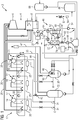
- FIG. 1 shows a schematic, simplified representation of a steam turbine plant 2.
- the steam turbine plant 2 has a steam turbine circuit 4.
- the steam turbine cycle 4 in turn comprises inter alia a three-stage steam turbine 6, a condenser unit 8 and a steam generator 10.
- the steam generator 10 comprises a condensate preheater 12, wherein the condensate preheater 12 is shown spatially separated from the other elements of the steam generator 10 for better representability. Further, the steam generator 10 comprises a first steam drum 14, a second steam drum 16 and a third steam drum 18. In the operation of the steam turbine plant 2 prevails in the first steam drum 14 (high-pressure drum), a higher pressure than in the second steam drum 16 (medium pressure drum), wherein in the second steam drum 16 again greater pressure prevails than in the third steam drum 18 (low-pressure drum).
- the steam generator 10 has a high-pressure superheater 20, a medium-pressure superheater 22 and a low-pressure superheater 24.
- the first steam drum 14 is associated with the high-pressure superheater 20.
- the second steam drum 16 is associated with the medium-pressure superheater 22 and accordingly the third steam drum 18 is associated with the low-pressure superheater 24.
- the respective superheater 20, 22, 24 is connected to its associated steam drum 14, 16, 18.
- the superheaters 20, 22, 24 are each connected via a main steam line 26 to the steam turbine 6.
- the steam turbine 6 is connected to the condenser unit 8.
- the condenser unit 8 in turn is connected to the condensate preheater 12.
- the condensate preheater 12 is connected via a line system 27 with the steam drums 14, 16, 18, said conduit system 27 for better clarity in FIG. 1 not fully illustrated.
- the steam generator 10 has three recirculations 28, each comprising a liquid intermediate reservoir 29 and a pump 30.
- Each of the three recirculations 28 is connected to one of the three superheaters 20, 22, 24 as well as to the steam drum 14, 16, 18 associated with the respective superheater 20, 22, 24.
- the recirculations 28 are used to return a (process) liquid, which passes from the respective steam drum 14, 16, 18 into the associated superheater 20, 22, 24 during operation of the steam turbine plant 2, back into the corresponding steam drum 14, 16, 18 due.
- the steam turbine plant 2 has a first separation device 32, which is designed as a separation vessel and in which a liquid-vapor separation is feasible.
- the first separating device 32 is connected to the first and the second steam drum 14, 16 in each case via a connecting line 34.
- the first separating device 32 is connected to the third steam drum 18 via a further connecting line 35.
- the first separator 32 is connected to a connecting tube 36 which connects the third steam drum 18 to the low pressure superheater 24.
- the latter (optional) compound figuratively not shown.
- a second separator 38 which is designed as a separation vessel and in which a liquid-vapor separation is feasible.
- the second separating device 38 includes a cold trap 40.
- a steam outlet line 42 is connected, via which steam from the second separator 38 can be discharged into the atmosphere.
- the second separator 38 is connected via a connecting line 41 with the third steam drum 18.
- the first separating device 32 is furthermore connected to the second separating device 38 via a branch line 43, which branches off from the further connecting line 35. Furthermore, the first separation device 32 is connected to the steam outlet line 42 via an additional connection line 44, which has a safety valve 45. If a pressure in the first separator 32 exceeds a predetermined maximum pressure, steam can be released from the first separator 32 into the atmosphere via the additional connecting line 44.
- the steam turbine plant 2 is equipped with a treatment plant 46 for the treatment of a liquid medium.
- the treatment plant 46 comprises a liquid circuit 48 with a vaporizer 50, a condenser 52, a feed pump 54 and a buffer memory 56.
- the liquid circuit 48 comprises a first 3-way valve 58 which is arranged between the evaporator 50 and the buffer memory 56. At this 3-way valve 58, a disposal line 60 is connected.
- the liquid circuit 48 comprises a first heat exchanger 62, a second heat exchanger 64 and a third heat exchanger 66. All three heat exchangers 62, 64, 66 are configured as liquid-liquid heat exchangers.
- the first heat exchanger 62 is connected on the input side with the first separator 32 and the output side with the buffer memory 56.
- the second heat exchanger 64 is connected on the input side to an output of the condensate preheater 12 and on the output side to an input of the condenser preheater 12.
- the third heat exchanger 66 is a component of a closed cooling system 68.
- liquid circuit 48 is interconnected by a system of conduits.
- the treatment plant 46 also includes a cooling circuit 70, in which a gaseous carrier medium is circulated.
- the aforementioned evaporator 50 and the condenser 52 are not only components of the fluid circuit 48, but also components of the refrigeration circuit 70.
- the refrigeration circuit 70 includes a fan 72, which is adapted to the gaseous carrier medium from the condenser 52 to the evaporator 50 and the evaporator 50 back to promote the capacitor 52.
- the evaporator 50 comprises a container 74 and a spray device 76 which is adapted to distribute or spray the medium to be treated in the container 74.
- the evaporator 50 has a carrier medium inlet device 78 which is adapted to admit and distribute the gaseous carrier medium into the container 74.
- the evaporator 50 has an inlet, not shown in the figure, which is provided to introduce an acid into the container 74.
- the treatment plant 46 has a degassing device 80, in particular a membrane degasser.
- the degassing device 80 is connected on the input side to the capacitor 52.
- the degassing device 80 is connected via a second 3-way valve 82 to an electrodeionization module 84, which in turn is connected on the output side to a first liquid reservoir 86.
- the second 3-way valve 82 is also connected to the condenser unit 8.
- the treatment plant 46 comprises a second liquid storage 88, which contains a demineralizing liquid, such as drinking water, and is connected to the buffer memory 56.
- a demineralizing liquid such as drinking water
- the steam from the steam turbine 6 is passed into the condenser unit 8, in which the vapor condenses out.
- the resulting condensate is fed back to the steam generator 10 and the process described is repeated cyclically.
- the contaminated process liquid in the present case, blowdown water, from the first and second steam drum 14, 16 is introduced into the first separator 32.
- the contaminated process liquid is introduced into the second separator 38.
- a liquid-vapor separation is performed.
- steam is separated from the contaminated process liquid by the contaminated process liquid in the first separator 32 is relaxed.
- a portion of the steam is introduced from the first separator 32 via the further connecting line 35 in the third steam drum.
- a portion of the steam from the first separator 32 is introduced into the connecting pipe 36, which connects the low pressure superheater 24 to the third steam drum 18.
- the steam is passed on to the steam turbine 6. In this way, steam for driving the steam turbine 6 is recovered (recovered) from the contaminated process liquid.
- a liquid is obtained in the liquid-vapor separation.
- This liquid is a liquid remaining in the liquid-vapor separation, which is obtained from the contaminated process liquid.
- the liquid, which is obtained in the liquid-vapor separation is introduced as a heating means in the first heat exchanger 62 and passed through the heat exchanger 62. From the first heat exchanger 62, the liquid is introduced into the buffer memory 56, wherein it forms part of a liquid medium to be treated.
- a liquid-vapor separation is also performed.
- a liquid is obtained in an analogous manner.
- This liquid is introduced from the second separator 38 directly into the buffer memory 56, wherein it forms another part of the medium to be processed.
- a vapor, which is recovered in the liquid-vapor separation in the second separator 38, is discharged via the steam outlet 42 into the atmosphere.
- a lower pressure prevails than in the first separating device 32.
- a pressure of a few bar can prevail in the first separating device 32, while in the second separating device 38, for example.
- Atmospheric pressure or (approximately) atmospheric pressure can prevail.
- the medium to be treated is heated in the liquid circuit 48 on the one hand by means of the first heat exchanger 62 and on the other hand by means of the second first heat exchanger 64, wherein in the second heat exchanger 64, a portion of the process liquid, which flows through the condensate preheater 12, is introduced as heating means. From the second heat exchanger 64, the process liquid is fed back into the condensate preheater 12.
- the medium to be treated is distributed or sprayed on entering the evaporator 50 by means of the spray device 76 in the container 76 of the evaporator 50.
- the fan 72 By means of the fan 72, air is used as a carrier medium against a flow direction, along which the medium to be treated flows in the evaporator, passed through the evaporator 50.
- Part of the distributed medium to be treated evaporates in the container 76, is taken up by the air and guided by the air into the condenser 52.
- an acid is introduced into the liquid circuit 48 in the evaporator 50, so that formation of carbonates in the medium to be treated is prevented or reduced.
- the part of the medium to be treated introduced into the buffer 56 is conveyed from the buffer 56 to the condenser 52.
- this part of the medium to be treated cools the evaporated part of the medium to be treated which is absorbed by the carrier medium.
- a condensate is obtained in the condenser 52 from the medium to be treated.
- the condensate is passed into the degassing device 80 and degassed by means of the degassing device 80. Furthermore, the condensate can be introduced via the second 3-way valve 82 directly into the steam turbine cycle 4, for example into the condenser unit 8, and used as process liquid for the steam turbine cycle 4. Alternatively, after degassing, the condensate may be first deionized using the electrodeionization module 84 to recover a condensed demineralized liquid (demineralized water). The demineralized liquid can be stored in the first memory 86 and be introduced as needed in the steam turbine circuit 4 as additional fluid (additional water).
- a residual liquid which remains in the liquid circuit 48 during or after the preparation of the medium can be removed via the disposal line 60 from the liquid circuit 48, for example to a cooling tower or an external disposal facility.
- the method described above makes it possible to reduce wastewater or waste water from the steam turbine plant 2.
- the method described above allows energy-efficient operation of the steam turbine plant 2, in particular because thermal energy contained in the contaminated process liquid can be used to a large extent for the treatment of the contaminated process liquid.
- the treatment plant 46 can be used in another way, which need not be coupled to the slurry of the steam drums 14, 16, 18, for obtaining a demineralized liquid.
- the demineralizing liquid contained in the second memory 88 may be introduced into the buffer memory 56 from the second memory 88. Subsequently, the liquid to be demineralized can pass through the liquid circuit 48 analogously to the manner described above. However, it is not necessary for a heating medium to be introduced into the first heat exchanger 62. That is, the first heat exchanger 62 can be used to guide the demineralizing liquid in the liquid circuit 46, but without heating them.
- FIG. 2 shows a schematic, simplified representation of another steam turbine plant 90th
- the further steam turbine plant 90 differs from the steam turbine plant 2 FIG. 1 among other things, in that it has no returns from the superheaters 20, 22, 24 to the steam drums 14, 16, 18. Instead, the further steam turbine plant 90 has two additional connecting lines 92, via which the high-pressure superheater 20 and the low-pressure superheater 22 are each connected to the first separating device 32. In addition, the further steam turbine installation 90 has an additional connection line 93, via which the low-pressure superheater 24 is connected to the second separation device 38.
- the contaminated process liquid from the first two steam drums 14, 16 and from the high pressure superheater 20 and the medium pressure superheater 22 is introduced into the first separator 32.
- the contaminated process liquid from the third steam drum 18 and from the low pressure superheater 24 is introduced into the second separator 32.
- the liquid, reprocessed medium is in this embodiment from the liquids together, which are obtained in a liquid-vapor separation in the first separator 32 and a liquid-vapor separation in the second separator 38 and the be introduced into the fluid circuit 48.
- the medium to be treated is analogous to the above, in conjunction with FIG. 1 prepared manner described.
Landscapes
- Engineering & Computer Science (AREA)
- Chemical & Material Sciences (AREA)
- Mechanical Engineering (AREA)
- General Engineering & Computer Science (AREA)
- Thermal Sciences (AREA)
- Physics & Mathematics (AREA)
- Chemical Kinetics & Catalysis (AREA)
- Water Supply & Treatment (AREA)
- Combustion & Propulsion (AREA)
- Life Sciences & Earth Sciences (AREA)
- Organic Chemistry (AREA)
- Hydrology & Water Resources (AREA)
- Environmental & Geological Engineering (AREA)
- Health & Medical Sciences (AREA)
- Urology & Nephrology (AREA)
- Analytical Chemistry (AREA)
- Molecular Biology (AREA)
- Electrochemistry (AREA)
- General Chemical & Material Sciences (AREA)
- Vaporization, Distillation, Condensation, Sublimation, And Cold Traps (AREA)
- Engine Equipment That Uses Special Cycles (AREA)
Claims (13)
- Procédé de préparation d'un fluide liquide, dans lequel on fait passer le fluide à préparer dans un circuit de liquide et on chauffe le fluide à préparer dans le circuit (48) de liquide, à l'aide d'un échangeur de chaleur (62), dans lequel, dans un dispositif (32) de séparation, on effectue une séparation liquide-vapeur et on envoie, comme fluide de chauffage, dans l'échangeur de chaleur (62), un liquide obtenu lors de la séparation liquide-vapeur,
caractérisé en ce que l'on fait passer un fluide porteur gazeux, notamment de l'air, en un circuit (70) de refroidissement, dans un évaporateur (50) et un condenseur (52), on répartit le fluide à préparer dans l'évaporateur (50), au moyen d'un système (76) de projection, on évapore au moins une partie du fluide à préparer reparti, ainsi qu'on l'absorbe par le fluide porteur gazeux et au moins une partie du fluide à préparer, évaporé et absorbé par le fluide porteur, se condense dans le condenseur (52). - Procédé suivant la revendication 1,
caractérisé en ce que l'on envoie, dans le dispositif (32) de séparation, un liquide pollué, notamment de l'eau de purge provenant d'un ballon (14, 16) à vapeur, dans lequel règne une première pression, à la séparation liquide-vapeur, on sépare de la vapeur du liquide pollué et on envoie la vapeur séparée du dispositif (32) de séparation à un élément d'un générateur (10 ) de vapeur, dans lequel il règne dans l'élément une deuxième pression, qui est plus basse que la première pression et on obtient le liquide, obtenu à la séparation liquide-vapeur, composé du liquide pollué. - Procédé suivant la revendication 2,
caractérisé en ce que l'élément du générateur (10 ) de vapeur, dans lequel on envoie la vapeur séparée du dispositif (32) de séparation, est un autre ballon (16, 18) à vapeur ou un élément, en aval de l'autre ballon (16, 18) à vapeur, du générateur (10) de vapeur. - Procédé suivant l'une des revendications précédentes,
caractérisé en ce que l'on fait passer, dans l'échangeur de chaleur (62), le liquide obtenu à la séparation du liquide-vapeur et on l'envoie de l'échangeur de chaleur (62) dans le circuit (48) de liquide, notamment à un accumulateur (56) tampon, le liquide, obtenu à la séparation du liquide-vapeur, formant au moins une partie du fluide à préparer. - Procédé suivant l'une des revendications précédentes,
caractérisé en ce que l'on obtient dans le condenseur (52) un produit condensé, qui est dégazé à l'aide d'un dispositif (80) de dégazage et on envoie le produit condensé dégazé dans un circuit (4) de turbine à vapeur et/ou on le déminéralise à l'aide d'un module (84) d'électrodéminéralisation. - Procédé suivant l'une des revendications précédentes,
caractérisé en ce que l'on chauffe le fluide à préparer dans le circuit (48) liquide, à l'aide d'un autre échangeur de chaleur (64), au moins une partie d'un liquide de processus, qui passe dans un préchauffeur (12) de produit condensé, étant envoyée, comme milieu de chauffage du préchauffeur (12) de produit condensé à l'autre échangeur de chaleur (64). - Procédé suivant l'une des revendications précédentes,
caractérisé en ce que l'on refroidit, caractérisé en ce que l'on refroidit, au moyen d'un échangeur de chaleur (66) supplémentaire, la partie du fluide à préparer, qui sort sous forme liquide d'un évaporateur (50) et on l'envoie dans un accumulateur (56) tampon. - Installation (46) de préparation pour préparer un fluide liquide, qui comprend un circuit (48) de liquide ayant un échangeur de chaleur (62) pour chauffer le fluide à préparer, comprenant un dispositif (32) de séparation, qui communique avec l'échangeur de chaleur (62) et dans lequel peut s'effectuer une séparation liquide-vapeur, un liquide obtenu à la séparation du liquide-vapeur pouvant être envoyé comme fluide de chauffage à l'échangeur de chaleur (62), caractérisé en ce qu'il est constitué par un condenseur (52), un évaporateur (50), ainsi qu'un ventilateur, un circuit (70) de refroidissement conçu pour véhiculer un fluide porteur gazeux du condenseur (52) à l'évaporateur (50) et de l'évaporateur (50) en retour au condenseur (52) et le fluide à préparer peut être réparti dans l'évaporateur (50) au moyen d'un système (76) de projection, de manière à ce qu'au moins une partie du fluide à préparer réparti soit évaporée, ainsi que puisse être absorbée par le fluide porteur gazeux et au moins une partie du fluide à préparer, évaporée et absorbée par le fluide porteur, puisse être condensée dans le condenseur (52).
- Installation de préparation suivant la revendication 8,
caractérisée en ce que le circuit (48) de liquide comprend un échangeur de chaleur (66) supplémentaire, conçu pour refroidir un liquide. - Installation (46) de préparation suivant l'une des revendications 8 ou 9,
caractérisé par un dispositif (80) de dégazage et un module (84) d'électrodéminéralisation, qui est relié au dispositif (80) de dégazage. - Installation (2, 90) de turbine à vapeur, ayant une installation (46) de préparation suivant l'une des revendications 8 à 10, un générateur de vapeur (10), ayant un premier ballon (14, 16) à vapeur, dans lequel règne une première pression, ainsi qu'un deuxième ballon (16, 18) à vapeur, dans lequel règne une deuxième pression plus basse, le dispositif (32) de séparation communiquant avec le premier ballon (14, 16) à vapeur et avec le deuxième ballon (16, 18) à vapeur.
- Installation (2, 90) à turbine à vapeur suivant la revendication 11,
caractérisé par un préchauffeur (12) de produit condensé, dans laquelle le circuit (48) de liquide comprend, pour chauffer le fluide à préparer, un autre échangeur de chaleur (64), qui communique avec le préchauffeur (12) de produit condensé. - Utilisation de l'installation (46) de préparation suivant l'une des revendications 8 à 10, pour obtenir un liquide de processus pour un circuit (4) de turbine à vapeur et/ou pour obtenir un liquide déminéralisé.
Applications Claiming Priority (2)
| Application Number | Priority Date | Filing Date | Title |
|---|---|---|---|
| DE102015206484.0A DE102015206484A1 (de) | 2015-04-10 | 2015-04-10 | Verfahren zum Aufbereiten eines flüssigen Mediums und Aufbereitungsanlage |
| PCT/EP2016/057095 WO2016162264A1 (fr) | 2015-04-10 | 2016-03-31 | Procédé servant à préparer un milieu fluide et installation de préparation |
Publications (2)
| Publication Number | Publication Date |
|---|---|
| EP3280883A1 EP3280883A1 (fr) | 2018-02-14 |
| EP3280883B1 true EP3280883B1 (fr) | 2019-02-20 |
Family
ID=55661412
Family Applications (1)
| Application Number | Title | Priority Date | Filing Date |
|---|---|---|---|
| EP16714372.6A Not-in-force EP3280883B1 (fr) | 2015-04-10 | 2016-03-31 | Procédé servant à préparer un milieu fluide et installation de préparation |
Country Status (4)
| Country | Link |
|---|---|
| US (1) | US20180080646A1 (fr) |
| EP (1) | EP3280883B1 (fr) |
| DE (1) | DE102015206484A1 (fr) |
| WO (1) | WO2016162264A1 (fr) |
Families Citing this family (2)
| Publication number | Priority date | Publication date | Assignee | Title |
|---|---|---|---|---|
| JP6963492B2 (ja) * | 2017-12-21 | 2021-11-10 | 三菱パワー株式会社 | 湿分分離設備、発電プラント、及び蒸気タービンの運転方法 |
| CN112762430B (zh) * | 2021-02-04 | 2025-07-15 | 华电新疆发电有限公司昌吉分公司 | 一种冬季空预器防污堵的暖风器疏水结构 |
Family Cites Families (14)
| Publication number | Priority date | Publication date | Assignee | Title |
|---|---|---|---|---|
| DE3427302A1 (de) * | 1984-07-20 | 1986-01-30 | Kraftwerk Union AG, 4330 Mülheim | Dampfkraftanlage zur erzeugung von dampf aus salzhaltigem rohwasser |
| AUPN692695A0 (en) * | 1995-12-01 | 1996-01-04 | Thermal Energy Accumulator Products Pty Ltd | Water purification plant |
| US7487640B2 (en) * | 2004-01-20 | 2009-02-10 | Siemens Aktiengesellschaft | Method and device for removing water from a steam plant |
| EP1662096A1 (fr) * | 2004-11-30 | 2006-05-31 | Siemens Aktiengesellschaft | Procédé de fonctionnement d'une centrale à vapeur, notamment d'une centrale à vapeur pour la production de l'éléctricité au moins et la centrale à vapeur correspondante |
| EP1806533A1 (fr) * | 2006-01-05 | 2007-07-11 | Siemens Aktiengesellschaft | Cycle à vapeur d'une centrale électrique |
| EP2076465A2 (fr) * | 2006-10-10 | 2009-07-08 | The Texas A&M University System | Système de dessalement |
| US8292272B2 (en) * | 2009-09-04 | 2012-10-23 | Massachusetts Institute Of Technology | Water separation under reduced pressure |
| US8252092B2 (en) * | 2009-10-05 | 2012-08-28 | Massachusetts Institute Of Technology | Water separation under varied pressure |
| US8539750B2 (en) * | 2010-04-30 | 2013-09-24 | Siemens Energy, Inc. | Energy recovery and steam supply for power augmentation in a combined cycle power generation system |
| JP2012016696A (ja) * | 2010-06-09 | 2012-01-26 | Kobelco Eco-Solutions Co Ltd | 淡水生成装置および淡水生成方法 |
| JP5902512B2 (ja) * | 2012-03-02 | 2016-04-13 | ヤンマー株式会社 | 廃熱回収ランキンサイクルシステム |
| CN202955680U (zh) * | 2012-11-28 | 2013-05-29 | 中冶东方工程技术有限公司 | 一种锅炉排污水热量利用设备 |
| EP2746656A1 (fr) * | 2012-12-19 | 2014-06-25 | Siemens Aktiengesellschaft | Drainage d'une centrale |
| CN204200521U (zh) * | 2014-10-24 | 2015-03-11 | 大唐辽源发电厂 | 一工一备双配置真空泵冷却水源 |
-
2015
- 2015-04-10 DE DE102015206484.0A patent/DE102015206484A1/de not_active Withdrawn
-
2016
- 2016-03-31 WO PCT/EP2016/057095 patent/WO2016162264A1/fr not_active Ceased
- 2016-03-31 US US15/561,759 patent/US20180080646A1/en not_active Abandoned
- 2016-03-31 EP EP16714372.6A patent/EP3280883B1/fr not_active Not-in-force
Non-Patent Citations (1)
| Title |
|---|
| None * |
Also Published As
| Publication number | Publication date |
|---|---|
| EP3280883A1 (fr) | 2018-02-14 |
| DE102015206484A1 (de) | 2016-10-13 |
| US20180080646A1 (en) | 2018-03-22 |
| WO2016162264A1 (fr) | 2016-10-13 |
Similar Documents
| Publication | Publication Date | Title |
|---|---|---|
| EP3710136A1 (fr) | Procédé et dispositif pour obtenir de l'eau à partir de l'air ambiant | |
| EP1706667B1 (fr) | Procede et dispositif de deflegmation dans un groupe-vapeur | |
| EP3140519B1 (fr) | Procédé et système de fonctionnement d'une centrale à vapeur avec un dispositif de traitement thermique de l'eau | |
| DE1805652B2 (de) | Verfahren zur Gewinnung von Frischwasser aus einer wäßrigen Salzlösung sowie Vorrichtung zur Durchführung des Verfahrens | |
| EP3280883B1 (fr) | Procédé servant à préparer un milieu fluide et installation de préparation | |
| DE1140957B (de) | Absorptionskuehlsystem und Verfahren fuer den Betrieb desselben | |
| EP3402583B1 (fr) | Installation de distillation à basse température | |
| DE102013210425A1 (de) | Anlage und Verfahren zum Aufbereiten von Wasser | |
| DE2632910A1 (de) | Verfahren zum eindampfen von fluessigkeiten, insbesondere von radioaktiven abwaessern | |
| DE102013208002A1 (de) | Thermische Wasseraufbereitung bei STIG Kraftwerkskonzepten | |
| EP3458180B1 (fr) | Procédé et dispositif pour obtenir de l'eau à partir de l'air ambiant | |
| EP3130383A1 (fr) | Centrale electrique combinée avec un système thermique de dessalement d'eau de mer | |
| DE102009007193A1 (de) | Verfahren und Anordnung zum Reinigen salzhaltigen Wassers mittels heisser Abgase | |
| DE3828882A1 (de) | Vorrichtung zur speisewasseraufbereitung fuer ein kraftwerk | |
| DE3503863A1 (de) | Anlage mit einem waerme aufnehmenden und waerme abgebenden prozessteil sowie einem eine absorbereinrichtung enthaltenden waermeversorgungsteil | |
| DE102016107984A1 (de) | Meerwasserentsalzungsvorrichtung zum Entsalzen von Meerwasser | |
| EP4435238A2 (fr) | Procédé et dispositif de production de vapeur pour produire de la vapeur de traitement | |
| DE2717505A1 (de) | Zweistufiger verdampfer | |
| WO2019096889A1 (fr) | Procédé et dispositif pour obtenir de l'eau à partir de l'air ambiant | |
| AT528334B1 (de) | Vorrichtung zur Rückgewinnung der Wärme aus mindestens zwei unterschiedlichen Dampfströmen, Anlage, Verwendung und Verfahren | |
| DE3427302C2 (fr) | ||
| DE102009031246A1 (de) | Ein- oder mehrstufiger kombinierter Verdampfer und Kondensator für kleine Wasserentsalzungs-/-reinigungsmaschine | |
| WO2008141784A2 (fr) | Procédé de refroidissement d'un gaz de processus renfermant de l'hydrogène et de la vapeur d'eau, issu d'une installation de production d'hydrogène | |
| DE102008004107A1 (de) | Verfahren und Anlage zur Entsalzung von Salzwasser unter Verwendung von MSF-Entsalzungseinheiten mit einem Dampfumlaufsystem | |
| DE19723566C1 (de) | Verfahren zum Vakuumverdampfen von einem mit einem Lösungsmittel versetzten Substrat sowie Vorrichtung zur Durchführung des Verfahrens |
Legal Events
| Date | Code | Title | Description |
|---|---|---|---|
| STAA | Information on the status of an ep patent application or granted ep patent |
Free format text: STATUS: THE INTERNATIONAL PUBLICATION HAS BEEN MADE |
|
| PUAI | Public reference made under article 153(3) epc to a published international application that has entered the european phase |
Free format text: ORIGINAL CODE: 0009012 |
|
| STAA | Information on the status of an ep patent application or granted ep patent |
Free format text: STATUS: REQUEST FOR EXAMINATION WAS MADE |
|
| 17P | Request for examination filed |
Effective date: 20170901 |
|
| AK | Designated contracting states |
Kind code of ref document: A1 Designated state(s): AL AT BE BG CH CY CZ DE DK EE ES FI FR GB GR HR HU IE IS IT LI LT LU LV MC MK MT NL NO PL PT RO RS SE SI SK SM TR |
|
| AX | Request for extension of the european patent |
Extension state: BA ME |
|
| REG | Reference to a national code |
Ref country code: DE Ref legal event code: R079 Ref document number: 502016003462 Country of ref document: DE Free format text: PREVIOUS MAIN CLASS: F01K0007060000 Ipc: F22D0011000000 |
|
| DAV | Request for validation of the european patent (deleted) | ||
| DAX | Request for extension of the european patent (deleted) | ||
| RIC1 | Information provided on ipc code assigned before grant |
Ipc: F01K 7/16 20060101ALI20180712BHEP Ipc: F22B 37/50 20060101ALI20180712BHEP Ipc: F01K 7/06 20060101ALI20180712BHEP Ipc: F22B 37/26 20060101ALI20180712BHEP Ipc: F01K 25/00 20060101ALI20180712BHEP Ipc: F22B 37/48 20060101ALI20180712BHEP Ipc: F22D 11/00 20060101AFI20180712BHEP |
|
| GRAP | Despatch of communication of intention to grant a patent |
Free format text: ORIGINAL CODE: EPIDOSNIGR1 |
|
| STAA | Information on the status of an ep patent application or granted ep patent |
Free format text: STATUS: GRANT OF PATENT IS INTENDED |
|
| INTG | Intention to grant announced |
Effective date: 20180912 |
|
| GRAS | Grant fee paid |
Free format text: ORIGINAL CODE: EPIDOSNIGR3 |
|
| GRAA | (expected) grant |
Free format text: ORIGINAL CODE: 0009210 |
|
| STAA | Information on the status of an ep patent application or granted ep patent |
Free format text: STATUS: THE PATENT HAS BEEN GRANTED |
|
| AK | Designated contracting states |
Kind code of ref document: B1 Designated state(s): AL AT BE BG CH CY CZ DE DK EE ES FI FR GB GR HR HU IE IS IT LI LT LU LV MC MK MT NL NO PL PT RO RS SE SI SK SM TR |
|
| REG | Reference to a national code |
Ref country code: GB Ref legal event code: FG4D Free format text: NOT ENGLISH |
|
| REG | Reference to a national code |
Ref country code: CH Ref legal event code: EP |
|
| REG | Reference to a national code |
Ref country code: DE Ref legal event code: R096 Ref document number: 502016003462 Country of ref document: DE |
|
| REG | Reference to a national code |
Ref country code: AT Ref legal event code: REF Ref document number: 1098671 Country of ref document: AT Kind code of ref document: T Effective date: 20190315 |
|
| REG | Reference to a national code |
Ref country code: IE Ref legal event code: FG4D Free format text: LANGUAGE OF EP DOCUMENT: GERMAN |
|
| PGFP | Annual fee paid to national office [announced via postgrant information from national office to epo] |
Ref country code: FR Payment date: 20190322 Year of fee payment: 4 |
|
| REG | Reference to a national code |
Ref country code: LT Ref legal event code: MG4D |
|
| REG | Reference to a national code |
Ref country code: NL Ref legal event code: MP Effective date: 20190220 |
|
| PG25 | Lapsed in a contracting state [announced via postgrant information from national office to epo] |
Ref country code: LT Free format text: LAPSE BECAUSE OF FAILURE TO SUBMIT A TRANSLATION OF THE DESCRIPTION OR TO PAY THE FEE WITHIN THE PRESCRIBED TIME-LIMIT Effective date: 20190220 Ref country code: SE Free format text: LAPSE BECAUSE OF FAILURE TO SUBMIT A TRANSLATION OF THE DESCRIPTION OR TO PAY THE FEE WITHIN THE PRESCRIBED TIME-LIMIT Effective date: 20190220 Ref country code: NO Free format text: LAPSE BECAUSE OF FAILURE TO SUBMIT A TRANSLATION OF THE DESCRIPTION OR TO PAY THE FEE WITHIN THE PRESCRIBED TIME-LIMIT Effective date: 20190520 Ref country code: PT Free format text: LAPSE BECAUSE OF FAILURE TO SUBMIT A TRANSLATION OF THE DESCRIPTION OR TO PAY THE FEE WITHIN THE PRESCRIBED TIME-LIMIT Effective date: 20190620 Ref country code: FI Free format text: LAPSE BECAUSE OF FAILURE TO SUBMIT A TRANSLATION OF THE DESCRIPTION OR TO PAY THE FEE WITHIN THE PRESCRIBED TIME-LIMIT Effective date: 20190220 |
|
| PG25 | Lapsed in a contracting state [announced via postgrant information from national office to epo] |
Ref country code: IS Free format text: LAPSE BECAUSE OF FAILURE TO SUBMIT A TRANSLATION OF THE DESCRIPTION OR TO PAY THE FEE WITHIN THE PRESCRIBED TIME-LIMIT Effective date: 20190620 Ref country code: RS Free format text: LAPSE BECAUSE OF FAILURE TO SUBMIT A TRANSLATION OF THE DESCRIPTION OR TO PAY THE FEE WITHIN THE PRESCRIBED TIME-LIMIT Effective date: 20190220 Ref country code: LV Free format text: LAPSE BECAUSE OF FAILURE TO SUBMIT A TRANSLATION OF THE DESCRIPTION OR TO PAY THE FEE WITHIN THE PRESCRIBED TIME-LIMIT Effective date: 20190220 Ref country code: BG Free format text: LAPSE BECAUSE OF FAILURE TO SUBMIT A TRANSLATION OF THE DESCRIPTION OR TO PAY THE FEE WITHIN THE PRESCRIBED TIME-LIMIT Effective date: 20190520 Ref country code: GR Free format text: LAPSE BECAUSE OF FAILURE TO SUBMIT A TRANSLATION OF THE DESCRIPTION OR TO PAY THE FEE WITHIN THE PRESCRIBED TIME-LIMIT Effective date: 20190521 Ref country code: HR Free format text: LAPSE BECAUSE OF FAILURE TO SUBMIT A TRANSLATION OF THE DESCRIPTION OR TO PAY THE FEE WITHIN THE PRESCRIBED TIME-LIMIT Effective date: 20190220 Ref country code: NL Free format text: LAPSE BECAUSE OF FAILURE TO SUBMIT A TRANSLATION OF THE DESCRIPTION OR TO PAY THE FEE WITHIN THE PRESCRIBED TIME-LIMIT Effective date: 20190220 |
|
| REG | Reference to a national code |
Ref country code: DE Ref legal event code: R119 Ref document number: 502016003462 Country of ref document: DE |
|
| PG25 | Lapsed in a contracting state [announced via postgrant information from national office to epo] |
Ref country code: ES Free format text: LAPSE BECAUSE OF FAILURE TO SUBMIT A TRANSLATION OF THE DESCRIPTION OR TO PAY THE FEE WITHIN THE PRESCRIBED TIME-LIMIT Effective date: 20190220 Ref country code: AL Free format text: LAPSE BECAUSE OF FAILURE TO SUBMIT A TRANSLATION OF THE DESCRIPTION OR TO PAY THE FEE WITHIN THE PRESCRIBED TIME-LIMIT Effective date: 20190220 Ref country code: SK Free format text: LAPSE BECAUSE OF FAILURE TO SUBMIT A TRANSLATION OF THE DESCRIPTION OR TO PAY THE FEE WITHIN THE PRESCRIBED TIME-LIMIT Effective date: 20190220 Ref country code: RO Free format text: LAPSE BECAUSE OF FAILURE TO SUBMIT A TRANSLATION OF THE DESCRIPTION OR TO PAY THE FEE WITHIN THE PRESCRIBED TIME-LIMIT Effective date: 20190220 Ref country code: CZ Free format text: LAPSE BECAUSE OF FAILURE TO SUBMIT A TRANSLATION OF THE DESCRIPTION OR TO PAY THE FEE WITHIN THE PRESCRIBED TIME-LIMIT Effective date: 20190220 Ref country code: DK Free format text: LAPSE BECAUSE OF FAILURE TO SUBMIT A TRANSLATION OF THE DESCRIPTION OR TO PAY THE FEE WITHIN THE PRESCRIBED TIME-LIMIT Effective date: 20190220 Ref country code: IT Free format text: LAPSE BECAUSE OF FAILURE TO SUBMIT A TRANSLATION OF THE DESCRIPTION OR TO PAY THE FEE WITHIN THE PRESCRIBED TIME-LIMIT Effective date: 20190220 Ref country code: EE Free format text: LAPSE BECAUSE OF FAILURE TO SUBMIT A TRANSLATION OF THE DESCRIPTION OR TO PAY THE FEE WITHIN THE PRESCRIBED TIME-LIMIT Effective date: 20190220 |
|
| REG | Reference to a national code |
Ref country code: CH Ref legal event code: PL |
|
| PG25 | Lapsed in a contracting state [announced via postgrant information from national office to epo] |
Ref country code: PL Free format text: LAPSE BECAUSE OF FAILURE TO SUBMIT A TRANSLATION OF THE DESCRIPTION OR TO PAY THE FEE WITHIN THE PRESCRIBED TIME-LIMIT Effective date: 20190220 Ref country code: SM Free format text: LAPSE BECAUSE OF FAILURE TO SUBMIT A TRANSLATION OF THE DESCRIPTION OR TO PAY THE FEE WITHIN THE PRESCRIBED TIME-LIMIT Effective date: 20190220 Ref country code: LU Free format text: LAPSE BECAUSE OF NON-PAYMENT OF DUE FEES Effective date: 20190331 |
|
| REG | Reference to a national code |
Ref country code: BE Ref legal event code: MM Effective date: 20190331 |
|
| PLBE | No opposition filed within time limit |
Free format text: ORIGINAL CODE: 0009261 |
|
| STAA | Information on the status of an ep patent application or granted ep patent |
Free format text: STATUS: NO OPPOSITION FILED WITHIN TIME LIMIT |
|
| PG25 | Lapsed in a contracting state [announced via postgrant information from national office to epo] |
Ref country code: MC Free format text: LAPSE BECAUSE OF FAILURE TO SUBMIT A TRANSLATION OF THE DESCRIPTION OR TO PAY THE FEE WITHIN THE PRESCRIBED TIME-LIMIT Effective date: 20190220 |
|
| 26N | No opposition filed |
Effective date: 20191121 |
|
| PG25 | Lapsed in a contracting state [announced via postgrant information from national office to epo] |
Ref country code: DE Free format text: LAPSE BECAUSE OF NON-PAYMENT OF DUE FEES Effective date: 20191001 Ref country code: LI Free format text: LAPSE BECAUSE OF NON-PAYMENT OF DUE FEES Effective date: 20190331 Ref country code: CH Free format text: LAPSE BECAUSE OF NON-PAYMENT OF DUE FEES Effective date: 20190331 Ref country code: IE Free format text: LAPSE BECAUSE OF NON-PAYMENT OF DUE FEES Effective date: 20190331 |
|
| PG25 | Lapsed in a contracting state [announced via postgrant information from national office to epo] |
Ref country code: BE Free format text: LAPSE BECAUSE OF NON-PAYMENT OF DUE FEES Effective date: 20190331 Ref country code: SI Free format text: LAPSE BECAUSE OF FAILURE TO SUBMIT A TRANSLATION OF THE DESCRIPTION OR TO PAY THE FEE WITHIN THE PRESCRIBED TIME-LIMIT Effective date: 20190220 |
|
| PG25 | Lapsed in a contracting state [announced via postgrant information from national office to epo] |
Ref country code: TR Free format text: LAPSE BECAUSE OF FAILURE TO SUBMIT A TRANSLATION OF THE DESCRIPTION OR TO PAY THE FEE WITHIN THE PRESCRIBED TIME-LIMIT Effective date: 20190220 |
|
| PG25 | Lapsed in a contracting state [announced via postgrant information from national office to epo] |
Ref country code: MT Free format text: LAPSE BECAUSE OF FAILURE TO SUBMIT A TRANSLATION OF THE DESCRIPTION OR TO PAY THE FEE WITHIN THE PRESCRIBED TIME-LIMIT Effective date: 20190220 |
|
| PG25 | Lapsed in a contracting state [announced via postgrant information from national office to epo] |
Ref country code: FR Free format text: LAPSE BECAUSE OF NON-PAYMENT OF DUE FEES Effective date: 20200331 |
|
| GBPC | Gb: european patent ceased through non-payment of renewal fee |
Effective date: 20200331 |
|
| PG25 | Lapsed in a contracting state [announced via postgrant information from national office to epo] |
Ref country code: GB Free format text: LAPSE BECAUSE OF NON-PAYMENT OF DUE FEES Effective date: 20200331 |
|
| PG25 | Lapsed in a contracting state [announced via postgrant information from national office to epo] |
Ref country code: CY Free format text: LAPSE BECAUSE OF FAILURE TO SUBMIT A TRANSLATION OF THE DESCRIPTION OR TO PAY THE FEE WITHIN THE PRESCRIBED TIME-LIMIT Effective date: 20190220 |
|
| PG25 | Lapsed in a contracting state [announced via postgrant information from national office to epo] |
Ref country code: HU Free format text: LAPSE BECAUSE OF FAILURE TO SUBMIT A TRANSLATION OF THE DESCRIPTION OR TO PAY THE FEE WITHIN THE PRESCRIBED TIME-LIMIT; INVALID AB INITIO Effective date: 20160331 |
|
| REG | Reference to a national code |
Ref country code: AT Ref legal event code: MM01 Ref document number: 1098671 Country of ref document: AT Kind code of ref document: T Effective date: 20210331 |
|
| PG25 | Lapsed in a contracting state [announced via postgrant information from national office to epo] |
Ref country code: MK Free format text: LAPSE BECAUSE OF FAILURE TO SUBMIT A TRANSLATION OF THE DESCRIPTION OR TO PAY THE FEE WITHIN THE PRESCRIBED TIME-LIMIT Effective date: 20190220 |
|
| PG25 | Lapsed in a contracting state [announced via postgrant information from national office to epo] |
Ref country code: AT Free format text: LAPSE BECAUSE OF NON-PAYMENT OF DUE FEES Effective date: 20210331 |