EP3280973B1 - Erhebungswinkelschätzungsvorrichtung und verfahren zur benutzerendgeräteplatzierung - Google Patents
Erhebungswinkelschätzungsvorrichtung und verfahren zur benutzerendgeräteplatzierung Download PDFInfo
- Publication number
- EP3280973B1 EP3280973B1 EP16777196.3A EP16777196A EP3280973B1 EP 3280973 B1 EP3280973 B1 EP 3280973B1 EP 16777196 A EP16777196 A EP 16777196A EP 3280973 B1 EP3280973 B1 EP 3280973B1
- Authority
- EP
- European Patent Office
- Prior art keywords
- image
- sky
- camera device
- objects
- user terminal
- Prior art date
- Legal status (The legal status is an assumption and is not a legal conclusion. Google has not performed a legal analysis and makes no representation as to the accuracy of the status listed.)
- Active
Links
Images




Classifications
-
- G—PHYSICS
- G01—MEASURING; TESTING
- G01B—MEASURING LENGTH, THICKNESS OR SIMILAR LINEAR DIMENSIONS; MEASURING ANGLES; MEASURING AREAS; MEASURING IRREGULARITIES OF SURFACES OR CONTOURS
- G01B11/00—Measuring arrangements characterised by the use of optical techniques
- G01B11/26—Measuring arrangements characterised by the use of optical techniques for measuring angles or tapers; for testing the alignment of axes
-
- H—ELECTRICITY
- H04—ELECTRIC COMMUNICATION TECHNIQUE
- H04N—PICTORIAL COMMUNICATION, e.g. TELEVISION
- H04N23/00—Cameras or camera modules comprising electronic image sensors; Control thereof
- H04N23/60—Control of cameras or camera modules
- H04N23/64—Computer-aided capture of images, e.g. transfer from script file into camera, check of taken image quality, advice or proposal for image composition or decision on when to take image
-
- G—PHYSICS
- G01—MEASURING; TESTING
- G01S—RADIO DIRECTION-FINDING; RADIO NAVIGATION; DETERMINING DISTANCE OR VELOCITY BY USE OF RADIO WAVES; LOCATING OR PRESENCE-DETECTING BY USE OF THE REFLECTION OR RERADIATION OF RADIO WAVES; ANALOGOUS ARRANGEMENTS USING OTHER WAVES
- G01S19/00—Satellite radio beacon positioning systems; Determining position, velocity or attitude using signals transmitted by such systems
-
- G—PHYSICS
- G01—MEASURING; TESTING
- G01S—RADIO DIRECTION-FINDING; RADIO NAVIGATION; DETERMINING DISTANCE OR VELOCITY BY USE OF RADIO WAVES; LOCATING OR PRESENCE-DETECTING BY USE OF THE REFLECTION OR RERADIATION OF RADIO WAVES; ANALOGOUS ARRANGEMENTS USING OTHER WAVES
- G01S19/00—Satellite radio beacon positioning systems; Determining position, velocity or attitude using signals transmitted by such systems
- G01S19/01—Satellite radio beacon positioning systems transmitting time-stamped messages, e.g. GPS [Global Positioning System], GLONASS [Global Orbiting Navigation Satellite System] or GALILEO
-
- G—PHYSICS
- G02—OPTICS
- G02B—OPTICAL ELEMENTS, SYSTEMS OR APPARATUS
- G02B13/00—Optical objectives specially designed for the purposes specified below
- G02B13/001—Miniaturised objectives for electronic devices, e.g. portable telephones, webcams, PDAs, small digital cameras
- G02B13/0015—Miniaturised objectives for electronic devices, e.g. portable telephones, webcams, PDAs, small digital cameras characterised by the lens design
-
- H—ELECTRICITY
- H04—ELECTRIC COMMUNICATION TECHNIQUE
- H04N—PICTORIAL COMMUNICATION, e.g. TELEVISION
- H04N17/00—Diagnosis, testing or measuring for television systems or their details
-
- H—ELECTRICITY
- H04—ELECTRIC COMMUNICATION TECHNIQUE
- H04N—PICTORIAL COMMUNICATION, e.g. TELEVISION
- H04N23/00—Cameras or camera modules comprising electronic image sensors; Control thereof
- H04N23/60—Control of cameras or camera modules
- H04N23/63—Control of cameras or camera modules by using electronic viewfinders
- H04N23/633—Control of cameras or camera modules by using electronic viewfinders for displaying additional information relating to control or operation of the camera
- H04N23/635—Region indicators; Field of view indicators
-
- H—ELECTRICITY
- H04—ELECTRIC COMMUNICATION TECHNIQUE
- H04N—PICTORIAL COMMUNICATION, e.g. TELEVISION
- H04N23/00—Cameras or camera modules comprising electronic image sensors; Control thereof
- H04N23/60—Control of cameras or camera modules
- H04N23/698—Control of cameras or camera modules for achieving an enlarged field of view, e.g. panoramic image capture
Definitions
- the present disclosure relates to user terminals of non-geostationary satellite communications systems. More particularly, the present disclosure relates to a device and method for estimating the elevation angle of one or more objects surrounding a user terminal to help the user properly position the user terminal so that it has an unobstructed view of the sky.
- Satellite systems for bringing low-cost broadband internet service to any location on the earth are currently being developed. Such systems typically include gateway antennas that link the internet to a fleet of non-geostationary satellites, which in turn link to inexpensive user terminals positioned on the earth.
- the user terminals deliver internet connectivity to residences and businesses.
- the inexpensive user terminal mentioned above includes an antenna that requires an unobstructed view over a large section of the sky in all azimuthal directions (north, south, east, and west directions) in order to receive uninterrupted service from the satellites. Trees, buildings, and mountains must remain below a certain elevation angle (the angle above the horizon i.e., the line at which the earth and sky appear to meet) in all the azimuthal directions. In some parts of the world, the maximum elevation angle can be as low as about 45 degrees.
- An example of such a user terminal is described in U.S. Application Serial No. 14/627,577, filed February 20, 2015 and entitled "User Terminal Having A Linear Array Antenna With Electronic And Mechanical Actuation System.”
- the user should be capable of locating, mounting, installing, and positioning their user terminal without professional assistance. Because the user terminal must have an unobstructed view of the sky in all azimuthal directions, down to an elevation angle of about 45 degrees above the horizon in some applications, the ability of the user to locate and position their user terminal correctly is a significant challenge.
- users located and position their user terminal by visually estimating whether the terminal has an unobstructed view of the sky, which often leads to errors of up to 10 degrees and issues with dropout periods.
- Surveying equipment can be used to help locate and position the user terminals correctly, but such equipment is expensive and requires specialized skill to operate.
- an inexpensive and easy-to-use system and method are needed for allowing a user to accurately estimate the elevation angle of one or more surrounding objects so that the user can locate and position a user terminal of a non-geostationary satellite communications system so that it has an unobstructed view of the sky in all azimuthal directions down to an elevation angle of about 45 degrees.
- Document JPH0749372 discloses a vehicle equipped with a satellite tracking device comprising a video acquisition device and an antenna disposed on the top of the video acquisition device. A satellite monitoring picture is displayed with the positions of the satellite superimposed on it.
- the elevation motor of an elevator device carrying the video acquisition device is activated in order to lift upward the video acquisition device and avoid the obstruction.
- Document JP2004012171 discloses a positioning environment GPS (Global Positioning System) information generating/distributing system which for creates GPS sky image composite data combining sky image data and sky layout data of GPS satellites.
- GPS Global Positioning System
- Document JPH10163721 discloses a GPS antenna for topographical survey using GPS satellite.
- the GPS antenna is equipped with a camera fitted with a fish eye lens allowing to shoot the surrounding landscape.
- the invention relates to a system for estimating the elevation angle of one or more objects surrounding a user according to independent claim 1 and a method for estimating the elevation angle of one or more objects surroundings a user terminal according to independent claim 12.
- Other aspects of the invention are defined in the dependent claims.
- FIG. 1 illustrates an embodiment of an elevation angle estimating system 10 for allowing a user to accurately estimate the elevation angle of one or more surrounding objects, according to the present disclosure.
- the system 10 comprises a camera device 20 for capturing a real-time video image or a still image of the sky (sky image) and a display device 40 in communication with the camera device 20 to display the real-time video image or the still image of the sky, to a user.
- the camera device 20 and the display device 40 of the system 10 can be configured as separate components or units.
- the display device 40 can comprise a portable or mobile device with a display screen 42, such as a laptop computer or a hand held device, such as a smart phone or a tablet computer.
- the display device 40 in other embodiments, can comprise any device that is capable of communicating with the camera device 20 and displaying the sky image captured by the camera device 20, to the user.
- the camera device 20 of the system 10 can include an image sensor 22, an optical system 24, image processing/communication (IPC) electronics 26, a power source 28, an activation button 30, and a processor 32.
- the camera device 20 can be a part of the user terminal.
- An example of such a user terminal is described in U.S. Application Serial No. 14/627,577, filed February 20, 2015 and entitled "User Terminal Having A Linear Array Antenna With Electronic And Mechanical Actuation System.” The entire disclosure of U.S. Application Serial No. 14/627,577 is incorporated herein by reference. In such embodiments, as illustrated in FIG.
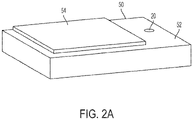
- the camera device 20 of the system 10 can be integrated into a housing 52 of the user terminal 50 adjacent to the antenna 54 thereof and positioned so that it faces up toward the sky.
- the camera device 20 preferably should fit within a volume of about 1.0 cm 3 . In such an embodiment the preferred length, width, and height of the volume are each about 1.0 cm.
- FIG. 2B Other embodiments of the camera device 20 of the system 10 may be configured as a portable unit 21 that can be removably mounted on the housing 52 of the user terminal 50, next to the antenna 54, facing up toward the sky, as illustrated in FIG. 2B .
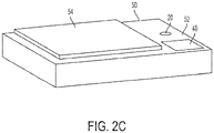
- the camera device 20 and the display device 40 of the system 10 can be integrated into the housing 52 of the user terminal 50 adjacent to the antenna 54 thereof and positioned so that the camera device 20 of the system 10 faces up toward the sky, as illustrated in FIG. 2C .
- the system 10 can be configured as a portable unit 11 that can be removably mounted on the housing 52 of the user terminal 50 next to the antenna 54, with the camera device 20 facing up toward the sky.
- the display 40 shown in the embodiments of FIGS. 2C and 2D can be configured to be rotated up about 45 to 90 degrees from the position illustrated in FIGS. 2C and 2D , so that the user does not obstruct the view of the camera 20 when viewing the display 40.
- the image sensor 22 of the camera device 20 can comprise digital image sensor such as a charge-coupled device (CDD) image sensor or a CMOS active-pixel sensor (APS) image sensor. Any other suitable image sensor capable of capturing a real time video image or a still image of the sky can be used in other embodiments of the camera device 20.
- digital image sensor such as a charge-coupled device (CDD) image sensor or a CMOS active-pixel sensor (APS) image sensor.
- CDD charge-coupled device
- APS CMOS active-pixel sensor
- the optical system 24 of the camera device 20 can comprise a wide angle lens arrangement 25 of one or more lenses, disposed in front of the image sensor 22.
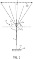
- the wide angle lens arrangement 25 has a focal length F which is substantially smaller than the focal length of a standard lens, where the focal length is the distance from the center C of the lens arrangement 25 to the image focal point or surface 22s of the image sensor 22 and where the focal length F of the standard lens is about 50 mm (converted into 35 mm film camera format).
- the wide angle lens arrangement 25 provides the image sensor 22 with a wide angle of view that allows a requisite edge-to-edge field-of-view (FOV) of the sky of at least 90 degrees to be included in the real-time video image or the still image captured by the image sensor 22.
- FOV edge-to-edge field-of-view
- the focal length F of the lens arrangement 25 will depend upon the FOV and the number and size of the pixels 22p of the image sensor 22.
- the wide angle lens arrangement 25 can have a focal length F between about 5 mm and about 35 mm (converted into 35 mm film camera format).
- the IPC electronics 26 of the camera device 20 may include video/still image acquisition firmware, hardware, and/or software and firmware, hardware, and/or software, for allowing the camera device 20 to wirelessly transmit the sky image to the display device 40.
- the IPC electronics 26 can include firmware for BLUETOOTH, Wi-Fi, Internet, and/or cellular data wireless transmission 60 of the sky image to the display device 40.
- the corresponding display device 40 can include firmware for receiving the BLUETOOTH, Wif-FI, Internet, and/or cellular data of the sky image transmitted by the IPC electronics 26 of the camera device 20 and a video or photo software application that allows viewing of the sky image on the display screen 42 of the display device 40.
- the IPC electronics 26 of the camera device 20 may alternatively or additionally include firmware, hardware, and/or software, for allowing the camera device 20 to transmit the sky image to the display device 40 via a wired connection 62.
- the firmware for wired transmission 62 may include, without limitation, firmware for using a Universal Serial Bus (USB) connection.
- USB Universal Serial Bus
- OTB USB On-The-Go
- the power source 28 of the camera device 20 can comprise a rechargeable battery or a replaceable battery. Alternatively or in addition to the battery, the power source 28 can comprise (or further comprise) a USB connection to the display device 40 (which can also serve to recharge the rechargeable battery if equipped therewith) and/or a standard power plug connection.
- the processor 32 of the camera device 20 can comprise a microprocessor that controls the functions of the IPC electronics 26, the activation button 30, and the image sensor 22.
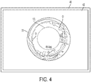
- the system 10 is further configured to superimpose or add a circular or like marking 51 (elevation limit circle) on or to the sky image 70 displayed on the display screen 42 of the display 40.
- the elevation limit circle 51 represents the locus of points at which obstructions exceed the maximum allowable elevation angle.
- the elevation limit circle 51 defines a maximum elevation angle above the horizon that objects surrounding the camera device 20 (and therefore, the user terminal), such as trees, buildings, mountains, and other structures in the FOV of the camera device's image sensor 22, must remain below so that the user terminal has an unobstructed view of the sky in all azimuthal directions and, therefore, can receive uninterrupted service from the satellites.
- the elevation limit circle 51 defines a maximum elevation angle EA ( FIG.
- the elevation limit circle 51 can define any other desirable maximum elevation angle EA above or below 45 degrees.
- Other embodiments of the system 10 can generate two or more concentric circular markings or elevation limit circles 51 on the sky image displayed on the display screen 42 of the display 40, which correspond to a different maximum elevation angles above the horizon that objects surrounding the camera device 20 must remain below.
- the elevation limit circle 51 can be generated in the sky image by providing a circular line in the optical system 24.
- the elevation limit circle can have other shapes, depending upon the parameters of the fleet or constellation of satellites and the pointing orientation of each satellite in the constellation.
- the optical system 24 can include a circular reticle that generates the elevation limit circle 51 which is superimposed over or on the sky image displayed on the display screen 42 of the display device 40.
- the elevation limit circle 51 may be electronically added to the real-time video image or still image by the video acquisition firmware of the camera device's IPC electronics 26. In still other embodiments, the elevation limit circle 51 may be electronically added to the real-time video image or still image by the software application running on the display device 40.
- the user Prior to using the system 10, the user should locate and position the user terminal so that the antenna is level (relative to the ground). Any conventional level indicating instrument, such as a bubble level, can be used to determine whether the antenna is level. Such an instrument can be separate from or integrated into the housing of the user terminal. If the camera device 20 or the elevation angle estimating system 10 is integrated into the user terminal 50 as illustrated in FIGS. 2A and 2C , respectively, the camera device 20 should be level when the antenna 54 is level. If the camera device 20 or system 10 is separate from the user terminal 50 as illustrated in FIGS. 2B and 2D , respectively, the camera device 20 or system 10 should be placed on the housing 52 of the user terminal 50 and leveled along with the antenna 54.
- Any conventional level indicating instrument such as a bubble level
- the camera device 20 is activated by the activation button 30.
- the camera device 20 then captures a real-time video image or still image of the sky and transmits it wirelessly or by wire to the display device 40.
- the proper location and position of the user terminal 50 is confirmed, if each one of the one or more of the objects O in the sky image 70 surrounding the user terminal 50 are substantially outside of the elevation limit circle 51, thereby indicating that the objects in the FOV of the camera device's image sensor 22 (and therefore the user terminal 50), are estimated to be below a desired maximum elevation angle. Consequently, the user terminal 50 has an unobstructed view of the sky in all azimuthal directions.
- the user terminal 50 has an obstructed view of the sky in at least one azimuthal direction. Accordingly, the user terminal should be repositioned, or relocated and positioned so that each of the objects O in the sky image 70 is substantially outside of the elevation limit circle 51.
- the elevation angle estimating system 10 of the present disclosure allows the user to estimate the elevation angle of surrounding objects to an accuracy of about 1 to 2 degrees, assuming the user terminal is level. Accordingly, the system 10 allows the user to estimate the elevation angle of surrounding objects with about 10 times the accuracy of prior art estimation methods where the user directly estimates the elevation angles of objects using only their eyes.
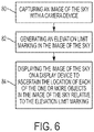
- FIG. 6 is a flowchart illustrating an embodiment of a method for estimating the elevation angle of one or more objects surrounding a user terminal with the system 10 of the present disclosure.
- an image of the sky is captured with the camera device 20 that is disposed on, attached to, disposed in, or disposed adjacent, to the user terminal 50.
- the elevation limit marking is generated in the image of the sky.
- the image of the sky is displayed on the display device 40 to ascertain the location of each of the one or more objects in the image relative to the elevation limit marking.
- each one of the one or more objects is substantially outside the elevation limit marking, all the one or more objects are estimated to be below the elevation angle, and if a portion of any one of the one or more objects is substantially inside the reflected image of the elevation limit marking, that object is estimated to be above the elevation angle.
Landscapes
- Engineering & Computer Science (AREA)
- Multimedia (AREA)
- Signal Processing (AREA)
- Physics & Mathematics (AREA)
- General Physics & Mathematics (AREA)
- Remote Sensing (AREA)
- Radar, Positioning & Navigation (AREA)
- Optics & Photonics (AREA)
- Computer Networks & Wireless Communication (AREA)
- Health & Medical Sciences (AREA)
- Biomedical Technology (AREA)
- General Health & Medical Sciences (AREA)
- Studio Devices (AREA)
- Length Measuring Devices By Optical Means (AREA)
Claims (13)
- Ein System (10), das es einem Benutzer ermöglicht, den Höhenwinkel (EA) eines oder mehrerer umgebender Objekte (O) präzise abzuschätzen, insbesondere ob das eine oder die mehreren Objekte (O) unterhalb oder oberhalb eines maximalen Höhenwinkels (EA) liegen, wobei das eine oder die mehreren Objekte (O) ein Terminal (50) umgeben, die eine Antenne (54) zur Kommunikation mit einem Satelliten in einem nicht-geostationären Satellitenkommunikationssystem hat, wobei das System (10) Folgendes aufweist:ein Kameragerät (20) zum Erfassen eines Echtzeitbildes (70) des Himmels, wobei das Kameragerät (20) einen Bildsensor (22) mit einer vorbestimmten Anzahl von Pixeln (22p) und eine Weitwinkellinsenanordnung (25) aufweist, wobei das Kameragerät (20) in das Gehäuse (52) des Terminals (50) benachbart zu der Antenne (54) des Terminals (50) integriert ist oder abnehmbar an dem Gehäuse (52) des Terminals (50) neben der Antenne (54) angebracht ist und ausgerichtet ist, um nach oben in Richtung des Himmels zu zeigen, wobei die Weitwinkellinse ein erforderliches Rand-zu-Rand-Sichtfeld (FOV, FOV = Field of View) des Himmels von mindestens 90 Grad bereitstellt, um in das Echtzeitbild eingebunden zu werden, das ein Videobild oder ein Standbild aufweist, das von dem Bildsensor (22) erfasst wird; undein Anzeigegerät (40) zum Anzeigen des Echtzeitbildes (70) des Himmels, das von dem Kameragerät (20) erfasst wurde;wobei entweder das Kameragerät (20) oder das Anzeigegerät (40) eine Höhengrenzmarkierung (51) erzeugt, die dem von dem Anzeigegerät (40) angezeigten Echtzeitbild (70) des Himmels überlagert wird, um einen maximalen Höhenwinkel (EA, EA = Elevation Angle) über einem Horizont der Erde anzuzeigen;wobei die Höhengrenzmarkierung (51) ein Kreis mit einem Durchmesser D ist, der in einer Anzahl von Pixeln (22p) des Bildsensors (22) gemessen wird und zwar gemäß:D in Anzahl von Pixeln (22p)=2∗(90-maximaler Höhenwinkel (EA) in Grad)/a, wobei α der Winkel in Grad ist, der von einem der Pixel (22p) des Bildsensors (22) gesehen wird,wobei das Terminal (50) und das Kameragerät (20) relativ zum Boden ausnivelliert sind; undwobei das System durch einen Benutzer neu positionierbar ist, bis alle des einen oder der mehreren Objekte (O) in einem Sichtfeld (FOV) des Kamerageräts (20) unter dem maximalen Höhenwinkel (EA) bleiben.
- Das System (10) nach Anspruch 1, wobei das Kameragerät (20) ein optisches System (24) zum Fokussieren von Licht, das den Himmel und das eine oder die mehreren Objekte (O) im Sichtfeld des Kamerageräts (20) darstellt, auf den Bildsensor (22) aufweist.
- Das System (10) nach Anspruch 1 oder 2, wobei das Kameragerät (20) eine Bildverarbeitungs- und Kommunikationselektronik (26) zur Bilderfassung und drahtlosen oder drahtgebundenen Übertragung des Bildes (70) des Himmels an das Anzeigegerät (40) aufweist.
- Das System (10) nach Anspruch 3, das ferner einen universellen seriellen On-The-Go-Bus-Adapter aufweist zur drahtgebundenen Verbindung des Kamerageräts (20) mit dem Anzeigegerät (40).
- Das System (10) nach einem der Ansprüche 3 bis 4, wobei die Bildverarbeitungs- und Kommunikationselektronik (26) die Höhengrenzmarkierung (51) zu dem auf dem Anzeigegerät (40) angezeigten Bild (70) des Himmels hinzufügt.
- System (10) nach einem der Ansprüche 1-5, wobei das Kameragerät (20) einen Prozessor (32) zur Steuerung der Funktionen der Bildverarbeitungs- und Kommunikationselektronik (26) enthält.
- System (10) nach einem der Ansprüche 1 bis 6, wobei das Anzeigegerät (40) ein tragbares oder mobiles Gerät mit einem Anzeigebildschirm (42) zum Anzeigen des von dem Kameragerät (20) aufgenommenen Bildes (70) des Himmels aufweist.
- System (10) nach einem der Ansprüche 1-7, wobei das Anzeigegerät (40) Firmware (60, 62), Hardware, Software oder eine beliebige Kombination davon für den drahtlosen oder drahtgebundenen Empfang des von dem Kameragerät (20) übertragenen Bildes (70) des Himmels enthält.
- System (10) nach einem der Ansprüche 1-8, wobei das Anzeigegerät (40) Firmware, Hardware, Software oder eine beliebige Kombination davon enthält, die die Höhengrenzmarkierung (50) zu dem auf dem Anzeigegerät (40) angezeigten Bild (70) des Himmels hinzufügt.
- System (10) nach einem der Ansprüche 1 bis 9, wobei, wenn sich das eine oder die mehreren Objekte (O) außerhalb der Höhengrenzmarkierung (51) befinden, das eine oder die mehreren Objekte (O) als unterhalb des Höhenwinkels (EA) liegend geschätzt werden.
- System (10) nach einem der Ansprüche 1 bis 9, wobei, wenn sich ein Teil eines der ein oder mehreren Objekte (O) innerhalb der Höhengrenzmarkierung (51) befindet, dieses eine der ein oder mehreren Objekte (O) als oberhalb des Höhenwinkels (EA) liegend geschätzt wird.
- Ein Verfahren, das es einem Benutzer ermöglicht, den Höhenwinkel (EA) eines oder mehrerer umgebender Objekte (O) präzise abzuschätzen, insbesondere ob das eine oder die mehreren Objekte (O) unterhalb oder oberhalb eines maximalen Höhenwinkels (EA) liegen, wobei das eine oder die mehreren Objekte (O) ein Terminal (50) umgeben, die eine Antenne (54) zur Kommunikation mit einem Satelliten in einem nicht-geostationären Satellitenkommunikationssystem hat, wobei das Verfahren Folgendes aufweist:Erfassen eines Echtzeitbildes (70) des Himmels mit einem Kameragerät (20), wobei das Kameragerät (20) eine Weitwinkellinsenanordnung (25) hat und einen Bildsensor (22) mit einer vorbestimmten Anzahl von Pixeln (22p) aufweist, wobei das Kameragerät (20) in das Gehäuse (52) des Terminals (50) benachbart zu der Antenne (54) des Terminals integriert ist oder abnehmbar an dem Gehäuse (52) des Terminals neben der Antenne (54) angebracht ist und ausgerichtet ist, um nach oben in Richtung des Himmels zu zeigen, wobei die Weitwinkellinse ein erforderliches Rand-zu-Rand-Sichtfeld (FOV, FOV = Field of View) des Himmels von mindestens 90 Grad bereitstellt, um in das Echtzeitbild eingebunden zu werden, das ein Videobild oder ein Standbild aufweist, das von dem Bildsensor erfasst wird;Anzeigen des Echtzeitbildes des Himmels auf einem Anzeigegerät (40);Überlagern einer Höhengrenzmarkierung (51) über dem angezeigten Echtzeitbild (70) des Himmels zum Anzeigen eines maximalen Höhenwinkels (EA, EA = Elevation Angle) über einem Horizont der Erde,wobei die Höhengrenzmarkierung (51) ein Kreis mit einem Durchmesser D ist, der in einer Anzahl von Pixeln (22p) des Bildsensors (22) gemessen wird und zwar gemäß:D in Anzahl von Pixeln (22p)=2∗(90-maximaler Höhenwinkel (EA) in Grad)/a, wobei α der Winkel in Grad ist, der von einem der Pixel (22p) des Bildsensors (22) gesehen wird; undwobei das Terminal (50) und das Kameragerät (20) relativ zum Boden ausnivelliert sind; undneu Positionieren des Systems durch einen Benutzer, bis alle des einen oder der mehreren Objekte (O) in einem Sichtfeld (FOV) des Kamerageräts (20) unter dem maximalen Höhenwinkel (EA) bleiben.
- Das Verfahren nach Anspruch 12, wobei wenn sich alle des einen oder der mehreren Objekte (O) außerhalb der Höhengrenzmarkierung (51) befinden, das eine oder die mehreren Objekte (O) als unterhalb des Höhenwinkels (EA) liegend geschätzt werden, und wenn sich ein Teil eines der ein oder mehreren Objekte (O) innerhalb der Höhengrenzmarkierung (51) befindet, dieses eine der ein oder mehreren Objekte (O) als oberhalb des Höhenwinkels (EA) liegend geschätzt wird.
Applications Claiming Priority (2)
| Application Number | Priority Date | Filing Date | Title |
|---|---|---|---|
| US14/679,702 US10415960B2 (en) | 2015-04-06 | 2015-04-06 | Elevation angle estimating system and method for user terminal placement |
| PCT/US2016/026207 WO2016164456A1 (en) | 2015-04-06 | 2016-04-06 | Elevation angle estimating system and method for user terminal placement |
Publications (3)
| Publication Number | Publication Date |
|---|---|
| EP3280973A1 EP3280973A1 (de) | 2018-02-14 |
| EP3280973A4 EP3280973A4 (de) | 2018-11-07 |
| EP3280973B1 true EP3280973B1 (de) | 2022-12-07 |
Family
ID=57017463
Family Applications (1)
| Application Number | Title | Priority Date | Filing Date |
|---|---|---|---|
| EP16777196.3A Active EP3280973B1 (de) | 2015-04-06 | 2016-04-06 | Erhebungswinkelschätzungsvorrichtung und verfahren zur benutzerendgeräteplatzierung |
Country Status (9)
| Country | Link |
|---|---|
| US (1) | US10415960B2 (de) |
| EP (1) | EP3280973B1 (de) |
| JP (1) | JP6771482B2 (de) |
| KR (1) | KR102134064B1 (de) |
| CN (1) | CN108283005B (de) |
| CA (1) | CA2980330C (de) |
| IL (1) | IL254590B (de) |
| SG (1) | SG11201707825VA (de) |
| WO (1) | WO2016164456A1 (de) |
Families Citing this family (4)
| Publication number | Priority date | Publication date | Assignee | Title |
|---|---|---|---|---|
| US10012503B2 (en) * | 2015-06-12 | 2018-07-03 | Worldvu Satellites Limited | Elevation angle estimating device and method for user terminal placement |
| TWI656692B (zh) * | 2015-12-31 | 2019-04-11 | 鴻海精密工業股份有限公司 | 通訊裝置 |
| US11619745B2 (en) * | 2019-10-29 | 2023-04-04 | Qualcomm Incorporated | Camera-based GNSS environment detector |
| US11943042B2 (en) * | 2020-10-13 | 2024-03-26 | Space Exploration Technologies Corp. | Apparatuses and methods for facilitating satellite visibility for earth-based antenna systems |
Family Cites Families (34)
| Publication number | Priority date | Publication date | Assignee | Title |
|---|---|---|---|---|
| US2410667A (en) | 1944-04-18 | 1946-11-05 | Eastman Kodak Co | Artificial horizon for sighting instruments |
| US2949808A (en) | 1956-07-03 | 1960-08-23 | Gen Motors Corp | Aerial gunsight |
| SE8904235D0 (sv) | 1989-12-15 | 1989-12-15 | Saab Space Ab | Anordning foer moejliggoerande av naermande och sammanfoerande av tvaa foeremaal, saerskilt rymdfarkoster |
| US5159401A (en) | 1990-09-06 | 1992-10-27 | Decker Jr John A | Elevation-angle sensing, celestial navigation and surveying |
| JPH0820511B2 (ja) | 1993-04-19 | 1996-03-04 | 日本電気株式会社 | 相対方位測定装置 |
| JPH0749372A (ja) | 1993-08-05 | 1995-02-21 | Mitsui Constr Co Ltd | 衛星監視装置 |
| JP3587912B2 (ja) * | 1995-09-22 | 2004-11-10 | 株式会社ソキア | Gps受信装置 |
| JPH10163721A (ja) | 1996-12-04 | 1998-06-19 | Nikon Corp | Gpsアンテナ |
| US6356296B1 (en) | 1997-05-08 | 2002-03-12 | Behere Corporation | Method and apparatus for implementing a panoptic camera system |
| EP1047955A1 (de) * | 1997-11-11 | 2000-11-02 | Franz Josef Lohmar | Verfahren und vorrichtung zur ermittlung von messzeiträumen für die vermessung von von sichthindernissen zumindest teilweise umgebenen punkten mittels satelliten |
| US6169881B1 (en) | 1998-05-04 | 2001-01-02 | Motorola, Inc. | Method and apparatus for predicting impending service outages for ground-to-satellite terminal in a satellite communication system |
| AU752675B2 (en) | 1998-09-03 | 2002-09-26 | Loma Linda University | Method for studying protein interactions (in vivo) |
| US6520647B2 (en) * | 2000-08-17 | 2003-02-18 | Mitsubishi Electric Research Laboratories Inc. | Automatic keystone correction for projectors with arbitrary orientation |
| JP2003258742A (ja) * | 2002-02-27 | 2003-09-12 | Tasada Kosakusho:Kk | 通信障害物調査装置 |
| JP2004012171A (ja) | 2002-06-04 | 2004-01-15 | Hitachi Industrial Equipment Systems Co Ltd | 測位環境gps情報作成頒布システムと作成頒布方法及び測位環境情報採取装置並びにコンピュータ・ソフトウエア |
| US7541975B2 (en) * | 2005-04-17 | 2009-06-02 | Trimble Navigation Limited | Enhanced GNSS signal processing |
| JP4617993B2 (ja) | 2005-04-28 | 2011-01-26 | ソニー株式会社 | 画像処理装置および画像処理方法、プログラム、並びに、記録媒体 |
| WO2008111306A1 (ja) | 2007-03-09 | 2008-09-18 | Panasonic Corporation | 蒸着装置および蒸着装置を用いた膜の製造方法 |
| WO2009017393A1 (en) * | 2007-07-31 | 2009-02-05 | Tele Atlas B.V. | Method and device for determining a position |
| US8601392B2 (en) * | 2007-08-22 | 2013-12-03 | 9224-5489 Quebec Inc. | Timeline for presenting information |
| JP2009288131A (ja) * | 2008-05-30 | 2009-12-10 | Seiko Epson Corp | 測位装置、測位システム、測位装置の制御方法、測位システムの制御方法、測位装置の制御プログラム及び測位システムの制御プログラム |
| US8570216B2 (en) * | 2008-05-30 | 2013-10-29 | The Boeing Company | Differential correction system enhancement leverages roving receivers enabled for a non-GPS, secondary PN and T signal to characterize local errors |
| EP2159779B1 (de) | 2008-08-27 | 2013-01-16 | Saab Ab | Verwendung von Bildsensor und Nachlauffilter für verbleibende Zeit, um Kollisionen in der Luft zu vermeiden |
| CN101424551B (zh) * | 2008-11-28 | 2010-08-04 | 北京航空航天大学 | 主动视觉非接触式伺服机构参数测量方法及其装置 |
| US8842878B2 (en) | 2008-12-16 | 2014-09-23 | Armageddon Energy, Inc. | Methods and systems for solar shade analysis |
| TW201030362A (en) | 2009-02-09 | 2010-08-16 | Univ Nat Taiwan | Method for implementing GPS surveying field work planning using 3D topographic information and method for analyzing 3D topographic information |
| DE102009054214B4 (de) * | 2009-11-21 | 2013-03-14 | Diehl Bgt Defence Gmbh & Co. Kg | Verfahren und Vorrichtung zum Erzeugen einer Darstellung einer Umgebung |
| US8638375B2 (en) * | 2011-05-17 | 2014-01-28 | Trimble Navigation Limited | Recording data with an integrated field-portable device |
| WO2013109742A1 (en) * | 2012-01-18 | 2013-07-25 | Logos Technologies, Inc. | Method, device, and system for computing a spherical projection image based on two-dimensional images |
| US8923622B2 (en) | 2012-12-10 | 2014-12-30 | Symbol Technologies, Inc. | Orientation compensation using a mobile device camera and a reference marker |
| JP2015033007A (ja) * | 2013-08-02 | 2015-02-16 | オリンパスイメージング株式会社 | 画像処理装置 |
| JP6030032B2 (ja) | 2013-08-30 | 2016-11-24 | 本田技研工業株式会社 | 音響処理装置、音響処理方法、及び音響処理プログラム |
| JP2015053557A (ja) * | 2013-09-05 | 2015-03-19 | キヤノン株式会社 | 撮像装置およびその制御方法、プログラムならびに記憶媒体 |
| US10012503B2 (en) | 2015-06-12 | 2018-07-03 | Worldvu Satellites Limited | Elevation angle estimating device and method for user terminal placement |
-
2015
- 2015-04-06 US US14/679,702 patent/US10415960B2/en active Active
-
2016
- 2016-04-06 EP EP16777196.3A patent/EP3280973B1/de active Active
- 2016-04-06 SG SG11201707825VA patent/SG11201707825VA/en unknown
- 2016-04-06 CN CN201680020026.XA patent/CN108283005B/zh not_active Expired - Fee Related
- 2016-04-06 JP JP2017552467A patent/JP6771482B2/ja not_active Expired - Fee Related
- 2016-04-06 WO PCT/US2016/026207 patent/WO2016164456A1/en not_active Ceased
- 2016-04-06 CA CA2980330A patent/CA2980330C/en active Active
- 2016-04-06 KR KR1020177031987A patent/KR102134064B1/ko not_active Expired - Fee Related
-
2017
- 2017-09-19 IL IL254590A patent/IL254590B/en unknown
Also Published As
| Publication number | Publication date |
|---|---|
| KR20190004211A (ko) | 2019-01-11 |
| JP6771482B2 (ja) | 2020-10-21 |
| CA2980330C (en) | 2020-07-21 |
| IL254590B (en) | 2022-03-01 |
| CN108283005A (zh) | 2018-07-13 |
| CN108283005B (zh) | 2021-01-19 |
| CA2980330A1 (en) | 2016-10-13 |
| US20160290794A1 (en) | 2016-10-06 |
| IL254590A0 (en) | 2017-11-30 |
| WO2016164456A1 (en) | 2016-10-13 |
| KR102134064B1 (ko) | 2020-07-14 |
| US10415960B2 (en) | 2019-09-17 |
| EP3280973A1 (de) | 2018-02-14 |
| SG11201707825VA (en) | 2017-10-30 |
| JP2018512819A (ja) | 2018-05-17 |
| EP3280973A4 (de) | 2018-11-07 |
Similar Documents
| Publication | Publication Date | Title |
|---|---|---|
| JP5656316B1 (ja) | マーカ装置を含むシステム及びこれを利用した方法 | |
| US10116893B1 (en) | Selectively controlling a direction of signal transmission using adaptive augmented reality | |
| US9503177B1 (en) | Methods and systems for aligning a satellite receiver dish using a smartphone or tablet device | |
| EP3280973B1 (de) | Erhebungswinkelschätzungsvorrichtung und verfahren zur benutzerendgeräteplatzierung | |
| CN110366670A (zh) | 三维形状推断方法、飞行体、移动平台、程序及记录介质 | |
| US20240380979A1 (en) | Portable device | |
| US20100085467A1 (en) | Image pickup device capable of providing gps coordinates of subject to be shot and method for detecting gps coordinates thereof | |
| EP3308425B1 (de) | Elevationswinkelschätzungsvorrichtung und verfahren zur benutzerendgeräteplatzierung | |
| JP5514062B2 (ja) | 電子機器、情報付き撮像画面表示方法及びプログラム | |
| JP4479386B2 (ja) | 撮影装置 | |
| JP4059154B2 (ja) | 情報送受信装置、情報送受信用プログラム | |
| JP2012047474A (ja) | 測位装置及び測位方法 | |
| US20190148813A1 (en) | Imaging system and method for accurately directing antennas | |
| JP2021169989A (ja) | 自己位置測定システム、車両、及び、自己位置測定方法 | |
| EP3278303B1 (de) | Vorrichtung zur benutzerendgeräteplatzierung | |
| CN216132445U (zh) | 观测设备及车载观测系统 | |
| JP2004320577A (ja) | 携帯移動端末 | |
| JP7629256B2 (ja) | 航空機情報共有システム | |
| JP2015065563A (ja) | 無線伝送システム | |
| JP2014071723A (ja) | 衛星観察情報提供システム | |
| KR101218219B1 (ko) | 지형 지물의 지피에스 좌표가 적용된 수치지도 보정 시스템 |
Legal Events
| Date | Code | Title | Description |
|---|---|---|---|
| STAA | Information on the status of an ep patent application or granted ep patent |
Free format text: STATUS: THE INTERNATIONAL PUBLICATION HAS BEEN MADE |
|
| PUAI | Public reference made under article 153(3) epc to a published international application that has entered the european phase |
Free format text: ORIGINAL CODE: 0009012 |
|
| STAA | Information on the status of an ep patent application or granted ep patent |
Free format text: STATUS: REQUEST FOR EXAMINATION WAS MADE |
|
| 17P | Request for examination filed |
Effective date: 20171011 |
|
| AK | Designated contracting states |
Kind code of ref document: A1 Designated state(s): AL AT BE BG CH CY CZ DE DK EE ES FI FR GB GR HR HU IE IS IT LI LT LU LV MC MK MT NL NO PL PT RO RS SE SI SK SM TR |
|
| AX | Request for extension of the european patent |
Extension state: BA ME |
|
| DAV | Request for validation of the european patent (deleted) | ||
| DAX | Request for extension of the european patent (deleted) | ||
| A4 | Supplementary search report drawn up and despatched |
Effective date: 20181009 |
|
| RIC1 | Information provided on ipc code assigned before grant |
Ipc: H04N 5/225 20060101ALI20181002BHEP Ipc: G06T 1/00 20060101ALI20181002BHEP Ipc: G01B 11/26 20060101AFI20181002BHEP Ipc: G06T 7/00 20170101ALI20181002BHEP |
|
| STAA | Information on the status of an ep patent application or granted ep patent |
Free format text: STATUS: EXAMINATION IS IN PROGRESS |
|
| 17Q | First examination report despatched |
Effective date: 20210521 |
|
| RAP3 | Party data changed (applicant data changed or rights of an application transferred) |
Owner name: WORLDVU SATELLITES LIMITED |
|
| REG | Reference to a national code |
Ref country code: DE Ref legal event code: R079 Ref document number: 602016076781 Country of ref document: DE Free format text: PREVIOUS MAIN CLASS: G01B0011260000 Ipc: H04N0005232000 |
|
| GRAP | Despatch of communication of intention to grant a patent |
Free format text: ORIGINAL CODE: EPIDOSNIGR1 |
|
| STAA | Information on the status of an ep patent application or granted ep patent |
Free format text: STATUS: GRANT OF PATENT IS INTENDED |
|
| RIC1 | Information provided on ipc code assigned before grant |
Ipc: H04N 17/00 20060101ALI20220624BHEP Ipc: H04N 5/232 20060101AFI20220624BHEP |
|
| INTG | Intention to grant announced |
Effective date: 20220713 |
|
| GRAS | Grant fee paid |
Free format text: ORIGINAL CODE: EPIDOSNIGR3 |
|
| GRAA | (expected) grant |
Free format text: ORIGINAL CODE: 0009210 |
|
| STAA | Information on the status of an ep patent application or granted ep patent |
Free format text: STATUS: THE PATENT HAS BEEN GRANTED |
|
| REG | Reference to a national code |
Ref country code: DE Ref legal event code: R079 Ref document number: 602016076781 Country of ref document: DE Free format text: PREVIOUS MAIN CLASS: H04N0005232000 Ipc: H04N0023600000 |
|
| AK | Designated contracting states |
Kind code of ref document: B1 Designated state(s): AL AT BE BG CH CY CZ DE DK EE ES FI FR GB GR HR HU IE IS IT LI LT LU LV MC MK MT NL NO PL PT RO RS SE SI SK SM TR |
|
| REG | Reference to a national code |
Ref country code: GB Ref legal event code: FG4D |
|
| REG | Reference to a national code |
Ref country code: CH Ref legal event code: EP Ref country code: AT Ref legal event code: REF Ref document number: 1537008 Country of ref document: AT Kind code of ref document: T Effective date: 20221215 |
|
| REG | Reference to a national code |
Ref country code: DE Ref legal event code: R096 Ref document number: 602016076781 Country of ref document: DE |
|
| REG | Reference to a national code |
Ref country code: IE Ref legal event code: FG4D |
|
| REG | Reference to a national code |
Ref country code: LT Ref legal event code: MG9D |
|
| REG | Reference to a national code |
Ref country code: NL Ref legal event code: MP Effective date: 20221207 |
|
| PG25 | Lapsed in a contracting state [announced via postgrant information from national office to epo] |
Ref country code: SE Free format text: LAPSE BECAUSE OF FAILURE TO SUBMIT A TRANSLATION OF THE DESCRIPTION OR TO PAY THE FEE WITHIN THE PRESCRIBED TIME-LIMIT Effective date: 20221207 Ref country code: NO Free format text: LAPSE BECAUSE OF FAILURE TO SUBMIT A TRANSLATION OF THE DESCRIPTION OR TO PAY THE FEE WITHIN THE PRESCRIBED TIME-LIMIT Effective date: 20230307 Ref country code: LT Free format text: LAPSE BECAUSE OF FAILURE TO SUBMIT A TRANSLATION OF THE DESCRIPTION OR TO PAY THE FEE WITHIN THE PRESCRIBED TIME-LIMIT Effective date: 20221207 Ref country code: FI Free format text: LAPSE BECAUSE OF FAILURE TO SUBMIT A TRANSLATION OF THE DESCRIPTION OR TO PAY THE FEE WITHIN THE PRESCRIBED TIME-LIMIT Effective date: 20221207 Ref country code: ES Free format text: LAPSE BECAUSE OF FAILURE TO SUBMIT A TRANSLATION OF THE DESCRIPTION OR TO PAY THE FEE WITHIN THE PRESCRIBED TIME-LIMIT Effective date: 20221207 |
|
| REG | Reference to a national code |
Ref country code: AT Ref legal event code: MK05 Ref document number: 1537008 Country of ref document: AT Kind code of ref document: T Effective date: 20221207 |
|
| PG25 | Lapsed in a contracting state [announced via postgrant information from national office to epo] |
Ref country code: RS Free format text: LAPSE BECAUSE OF FAILURE TO SUBMIT A TRANSLATION OF THE DESCRIPTION OR TO PAY THE FEE WITHIN THE PRESCRIBED TIME-LIMIT Effective date: 20221207 Ref country code: PL Free format text: LAPSE BECAUSE OF FAILURE TO SUBMIT A TRANSLATION OF THE DESCRIPTION OR TO PAY THE FEE WITHIN THE PRESCRIBED TIME-LIMIT Effective date: 20221207 Ref country code: LV Free format text: LAPSE BECAUSE OF FAILURE TO SUBMIT A TRANSLATION OF THE DESCRIPTION OR TO PAY THE FEE WITHIN THE PRESCRIBED TIME-LIMIT Effective date: 20221207 Ref country code: HR Free format text: LAPSE BECAUSE OF FAILURE TO SUBMIT A TRANSLATION OF THE DESCRIPTION OR TO PAY THE FEE WITHIN THE PRESCRIBED TIME-LIMIT Effective date: 20221207 Ref country code: GR Free format text: LAPSE BECAUSE OF FAILURE TO SUBMIT A TRANSLATION OF THE DESCRIPTION OR TO PAY THE FEE WITHIN THE PRESCRIBED TIME-LIMIT Effective date: 20230308 |
|
| PG25 | Lapsed in a contracting state [announced via postgrant information from national office to epo] |
Ref country code: NL Free format text: LAPSE BECAUSE OF FAILURE TO SUBMIT A TRANSLATION OF THE DESCRIPTION OR TO PAY THE FEE WITHIN THE PRESCRIBED TIME-LIMIT Effective date: 20221207 |
|
| PG25 | Lapsed in a contracting state [announced via postgrant information from national office to epo] |
Ref country code: SM Free format text: LAPSE BECAUSE OF FAILURE TO SUBMIT A TRANSLATION OF THE DESCRIPTION OR TO PAY THE FEE WITHIN THE PRESCRIBED TIME-LIMIT Effective date: 20221207 Ref country code: RO Free format text: LAPSE BECAUSE OF FAILURE TO SUBMIT A TRANSLATION OF THE DESCRIPTION OR TO PAY THE FEE WITHIN THE PRESCRIBED TIME-LIMIT Effective date: 20221207 Ref country code: PT Free format text: LAPSE BECAUSE OF FAILURE TO SUBMIT A TRANSLATION OF THE DESCRIPTION OR TO PAY THE FEE WITHIN THE PRESCRIBED TIME-LIMIT Effective date: 20230410 Ref country code: EE Free format text: LAPSE BECAUSE OF FAILURE TO SUBMIT A TRANSLATION OF THE DESCRIPTION OR TO PAY THE FEE WITHIN THE PRESCRIBED TIME-LIMIT Effective date: 20221207 Ref country code: CZ Free format text: LAPSE BECAUSE OF FAILURE TO SUBMIT A TRANSLATION OF THE DESCRIPTION OR TO PAY THE FEE WITHIN THE PRESCRIBED TIME-LIMIT Effective date: 20221207 Ref country code: AT Free format text: LAPSE BECAUSE OF FAILURE TO SUBMIT A TRANSLATION OF THE DESCRIPTION OR TO PAY THE FEE WITHIN THE PRESCRIBED TIME-LIMIT Effective date: 20221207 |
|
| PGFP | Annual fee paid to national office [announced via postgrant information from national office to epo] |
Ref country code: FR Payment date: 20230428 Year of fee payment: 8 Ref country code: DE Payment date: 20230412 Year of fee payment: 8 |
|
| PG25 | Lapsed in a contracting state [announced via postgrant information from national office to epo] |
Ref country code: SK Free format text: LAPSE BECAUSE OF FAILURE TO SUBMIT A TRANSLATION OF THE DESCRIPTION OR TO PAY THE FEE WITHIN THE PRESCRIBED TIME-LIMIT Effective date: 20221207 Ref country code: IS Free format text: LAPSE BECAUSE OF FAILURE TO SUBMIT A TRANSLATION OF THE DESCRIPTION OR TO PAY THE FEE WITHIN THE PRESCRIBED TIME-LIMIT Effective date: 20230407 Ref country code: AL Free format text: LAPSE BECAUSE OF FAILURE TO SUBMIT A TRANSLATION OF THE DESCRIPTION OR TO PAY THE FEE WITHIN THE PRESCRIBED TIME-LIMIT Effective date: 20221207 |
|
| REG | Reference to a national code |
Ref country code: DE Ref legal event code: R097 Ref document number: 602016076781 Country of ref document: DE |
|
| PLBE | No opposition filed within time limit |
Free format text: ORIGINAL CODE: 0009261 |
|
| STAA | Information on the status of an ep patent application or granted ep patent |
Free format text: STATUS: NO OPPOSITION FILED WITHIN TIME LIMIT |
|
| PG25 | Lapsed in a contracting state [announced via postgrant information from national office to epo] |
Ref country code: DK Free format text: LAPSE BECAUSE OF FAILURE TO SUBMIT A TRANSLATION OF THE DESCRIPTION OR TO PAY THE FEE WITHIN THE PRESCRIBED TIME-LIMIT Effective date: 20221207 |
|
| PGFP | Annual fee paid to national office [announced via postgrant information from national office to epo] |
Ref country code: GB Payment date: 20230424 Year of fee payment: 8 |
|
| 26N | No opposition filed |
Effective date: 20230908 |
|
| PG25 | Lapsed in a contracting state [announced via postgrant information from national office to epo] |
Ref country code: SI Free format text: LAPSE BECAUSE OF FAILURE TO SUBMIT A TRANSLATION OF THE DESCRIPTION OR TO PAY THE FEE WITHIN THE PRESCRIBED TIME-LIMIT Effective date: 20221207 |
|
| REG | Reference to a national code |
Ref country code: CH Ref legal event code: PL |
|
| PG25 | Lapsed in a contracting state [announced via postgrant information from national office to epo] |
Ref country code: LU Free format text: LAPSE BECAUSE OF NON-PAYMENT OF DUE FEES Effective date: 20230406 |
|
| REG | Reference to a national code |
Ref country code: BE Ref legal event code: MM Effective date: 20230430 |
|
| PG25 | Lapsed in a contracting state [announced via postgrant information from national office to epo] |
Ref country code: MC Free format text: LAPSE BECAUSE OF FAILURE TO SUBMIT A TRANSLATION OF THE DESCRIPTION OR TO PAY THE FEE WITHIN THE PRESCRIBED TIME-LIMIT Effective date: 20221207 |
|
| PG25 | Lapsed in a contracting state [announced via postgrant information from national office to epo] |
Ref country code: MC Free format text: LAPSE BECAUSE OF FAILURE TO SUBMIT A TRANSLATION OF THE DESCRIPTION OR TO PAY THE FEE WITHIN THE PRESCRIBED TIME-LIMIT Effective date: 20221207 Ref country code: LI Free format text: LAPSE BECAUSE OF NON-PAYMENT OF DUE FEES Effective date: 20230430 Ref country code: CH Free format text: LAPSE BECAUSE OF NON-PAYMENT OF DUE FEES Effective date: 20230430 |
|
| REG | Reference to a national code |
Ref country code: IE Ref legal event code: MM4A |
|
| PG25 | Lapsed in a contracting state [announced via postgrant information from national office to epo] |
Ref country code: BE Free format text: LAPSE BECAUSE OF NON-PAYMENT OF DUE FEES Effective date: 20230430 |
|
| PG25 | Lapsed in a contracting state [announced via postgrant information from national office to epo] |
Ref country code: IE Free format text: LAPSE BECAUSE OF NON-PAYMENT OF DUE FEES Effective date: 20230406 |
|
| PG25 | Lapsed in a contracting state [announced via postgrant information from national office to epo] |
Ref country code: IE Free format text: LAPSE BECAUSE OF NON-PAYMENT OF DUE FEES Effective date: 20230406 |
|
| PG25 | Lapsed in a contracting state [announced via postgrant information from national office to epo] |
Ref country code: IT Free format text: LAPSE BECAUSE OF FAILURE TO SUBMIT A TRANSLATION OF THE DESCRIPTION OR TO PAY THE FEE WITHIN THE PRESCRIBED TIME-LIMIT Effective date: 20221207 |
|
| REG | Reference to a national code |
Ref country code: DE Ref legal event code: R119 Ref document number: 602016076781 Country of ref document: DE |
|
| PG25 | Lapsed in a contracting state [announced via postgrant information from national office to epo] |
Ref country code: BG Free format text: LAPSE BECAUSE OF FAILURE TO SUBMIT A TRANSLATION OF THE DESCRIPTION OR TO PAY THE FEE WITHIN THE PRESCRIBED TIME-LIMIT Effective date: 20221207 |
|
| PG25 | Lapsed in a contracting state [announced via postgrant information from national office to epo] |
Ref country code: BG Free format text: LAPSE BECAUSE OF FAILURE TO SUBMIT A TRANSLATION OF THE DESCRIPTION OR TO PAY THE FEE WITHIN THE PRESCRIBED TIME-LIMIT Effective date: 20221207 |
|
| GBPC | Gb: european patent ceased through non-payment of renewal fee |
Effective date: 20240406 |
|
| PG25 | Lapsed in a contracting state [announced via postgrant information from national office to epo] |
Ref country code: DE Free format text: LAPSE BECAUSE OF NON-PAYMENT OF DUE FEES Effective date: 20241105 |
|
| PG25 | Lapsed in a contracting state [announced via postgrant information from national office to epo] |
Ref country code: GB Free format text: LAPSE BECAUSE OF NON-PAYMENT OF DUE FEES Effective date: 20240406 |
|
| PG25 | Lapsed in a contracting state [announced via postgrant information from national office to epo] |
Ref country code: FR Free format text: LAPSE BECAUSE OF NON-PAYMENT OF DUE FEES Effective date: 20240430 |
|
| PG25 | Lapsed in a contracting state [announced via postgrant information from national office to epo] |
Ref country code: GB Free format text: LAPSE BECAUSE OF NON-PAYMENT OF DUE FEES Effective date: 20240406 Ref country code: FR Free format text: LAPSE BECAUSE OF NON-PAYMENT OF DUE FEES Effective date: 20240430 Ref country code: DE Free format text: LAPSE BECAUSE OF NON-PAYMENT OF DUE FEES Effective date: 20241105 |
|
| PG25 | Lapsed in a contracting state [announced via postgrant information from national office to epo] |
Ref country code: CY Free format text: LAPSE BECAUSE OF FAILURE TO SUBMIT A TRANSLATION OF THE DESCRIPTION OR TO PAY THE FEE WITHIN THE PRESCRIBED TIME-LIMIT; INVALID AB INITIO Effective date: 20160406 |
|
| PG25 | Lapsed in a contracting state [announced via postgrant information from national office to epo] |
Ref country code: HU Free format text: LAPSE BECAUSE OF FAILURE TO SUBMIT A TRANSLATION OF THE DESCRIPTION OR TO PAY THE FEE WITHIN THE PRESCRIBED TIME-LIMIT; INVALID AB INITIO Effective date: 20160406 |
|
| PG25 | Lapsed in a contracting state [announced via postgrant information from national office to epo] |
Ref country code: TR Free format text: LAPSE BECAUSE OF FAILURE TO SUBMIT A TRANSLATION OF THE DESCRIPTION OR TO PAY THE FEE WITHIN THE PRESCRIBED TIME-LIMIT Effective date: 20221207 |