EP3281211B1 - Dispositif de transmission de courant continu - Google Patents
Dispositif de transmission de courant continu Download PDFInfo
- Publication number
- EP3281211B1 EP3281211B1 EP16719833.2A EP16719833A EP3281211B1 EP 3281211 B1 EP3281211 B1 EP 3281211B1 EP 16719833 A EP16719833 A EP 16719833A EP 3281211 B1 EP3281211 B1 EP 3281211B1
- Authority
- EP
- European Patent Office
- Prior art keywords
- coolant
- transmission line
- line
- superconducting
- transmission
- Prior art date
- Legal status (The legal status is an assumption and is not a legal conclusion. Google has not performed a legal analysis and makes no representation as to the accuracy of the status listed.)
- Active
Links
Images



Classifications
-
- H—ELECTRICITY
- H01—ELECTRIC ELEMENTS
- H01B—CABLES; CONDUCTORS; INSULATORS; SELECTION OF MATERIALS FOR THEIR CONDUCTIVE, INSULATING OR DIELECTRIC PROPERTIES
- H01B12/00—Superconductive or hyperconductive conductors, cables, or transmission lines
- H01B12/16—Superconductive or hyperconductive conductors, cables, or transmission lines characterised by cooling
-
- H—ELECTRICITY
- H01—ELECTRIC ELEMENTS
- H01B—CABLES; CONDUCTORS; INSULATORS; SELECTION OF MATERIALS FOR THEIR CONDUCTIVE, INSULATING OR DIELECTRIC PROPERTIES
- H01B12/00—Superconductive or hyperconductive conductors, cables, or transmission lines
- H01B12/02—Superconductive or hyperconductive conductors, cables, or transmission lines characterised by their form
-
- H—ELECTRICITY
- H01—ELECTRIC ELEMENTS
- H01B—CABLES; CONDUCTORS; INSULATORS; SELECTION OF MATERIALS FOR THEIR CONDUCTIVE, INSULATING OR DIELECTRIC PROPERTIES
- H01B12/00—Superconductive or hyperconductive conductors, cables, or transmission lines
- H01B12/14—Superconductive or hyperconductive conductors, cables, or transmission lines characterised by the disposition of thermal insulation
-
- H—ELECTRICITY
- H02—GENERATION; CONVERSION OR DISTRIBUTION OF ELECTRIC POWER
- H02G—INSTALLATION OF ELECTRIC CABLES OR LINES, OR OF COMBINED OPTICAL AND ELECTRIC CABLES OR LINES
- H02G15/00—Cable fittings
- H02G15/34—Cable fittings for cryogenic cables
-
- H—ELECTRICITY
- H10—SEMICONDUCTOR DEVICES; ELECTRIC SOLID-STATE DEVICES NOT OTHERWISE PROVIDED FOR
- H10N—ELECTRIC SOLID-STATE DEVICES NOT OTHERWISE PROVIDED FOR
- H10N60/00—Superconducting devices
- H10N60/20—Permanent superconducting devices
- H10N60/202—Permanent superconducting devices comprising metal borides, e.g. MgB2
-
- Y—GENERAL TAGGING OF NEW TECHNOLOGICAL DEVELOPMENTS; GENERAL TAGGING OF CROSS-SECTIONAL TECHNOLOGIES SPANNING OVER SEVERAL SECTIONS OF THE IPC; TECHNICAL SUBJECTS COVERED BY FORMER USPC CROSS-REFERENCE ART COLLECTIONS [XRACs] AND DIGESTS
- Y02—TECHNOLOGIES OR APPLICATIONS FOR MITIGATION OR ADAPTATION AGAINST CLIMATE CHANGE
- Y02E—REDUCTION OF GREENHOUSE GAS [GHG] EMISSIONS, RELATED TO ENERGY GENERATION, TRANSMISSION OR DISTRIBUTION
- Y02E40/00—Technologies for an efficient electrical power generation, transmission or distribution
- Y02E40/60—Superconducting electric elements or equipment; Power systems integrating superconducting elements or equipment
Definitions
- the present invention relates to a DC transmission apparatus comprising a superconducting transmission line having at least one superconductive conductor element and a cooling device for cooling a radially inner portion of the transmission line by means of a fluid coolant to a temperature below the transition temperature of the superconducting conductor element.
- intermediate cooling stations are used to cool the heated on a portion of the line coolant down again and feed again into the line interior.
- the cooling medium flowing along the line length is heated to such an extent by the thermal coupling with the environment as well as by mechanical friction and remaining electrical losses that the required operating temperature of the superconductor can no longer be guaranteed beyond a certain line length without such intermediate cooling stations.
- the use of such intermediate cooling stations leads to a comparatively large amount of equipment. Installation of such intermediate cooling stations may still be responsible for laying the transmission lines over land or in the ground, but the use of longer superconducting transmission lines than submarine cables would be completely uninteresting, both technically and economically, due to the need for submerged intermediate cooling stations.
- the object of the invention is therefore to provide a device for DC transmission, which overcomes the disadvantages mentioned.
- a device should be made available, which enables a transmission of high electrical power over longer distances with little equipment.
- the device according to the invention for DC transmission has a superconducting transmission line with at least one superconducting conductor element and a cooling device for cooling a radially inner region the transmission line by means of a fluid coolant to a temperature below the transition temperature of the superconducting conductor element.
- the superconducting transmission line has a vacuum-insulated sheath for thermal separation of the inner portion of the line from a warmer outer environment.
- the cooling device comprises at least one feed device for feeding coolant at an end region of the line into the inner region of the transmission line.
- the line has a longitudinal extent of at least 20 km and is free on this length of axially inwardly arranged feed devices for feeding coolant.
- the transmission line has such feeding devices only at most at its both ends.
- no feed devices for feeding coolant are arranged in an interior of the conduit.
- either only a single feed device may be present at only one end of the line, or there may be a total of feed devices at both ends of the line.
- the core idea of the present invention is that the superconducting conductor element is thermally sufficiently separated from the external environment by the vacuum-insulated casing and the electrical losses and mechanical frictional losses are kept sufficiently low to avoid intermediate cooling stations on internal sections of the pipe. Due to the thermal separation and the low losses, the superconducting conductor element is maintained at an operating temperature below the transition temperature of the superconductor by the cooling effect of the fluid coolant over the entire length of the conduit.
- a superconducting transmission line can then be used as a submarine cable under water.
- the line can in principle be laid underground as well Cable and / or be laid as overland cable. The use as a submarine cable over lengths of more than 10 km is made possible by the inventive design in the first place.
- An advantage over devices for DC transmission with normal conducting transmission lines is that with such a device according to the invention a very high current carrying capacity can be achieved. As a result, the transmission of high power is already possible in medium voltage ranges. Furthermore, high powers can advantageously be transmitted via a two-pole line, in which two superconducting conductors are led together within a vacuum insulation.
- a method for cooling a superconductive conductor element in such a device to a temperature below its transition temperature is characterized in that the fluid coolant is fed into the inner region of the conduit only at one or two end regions of the conduit.
- the advantages of the method are analogous to the advantages of the device according to the invention.
- the transmission line has a longitudinal extent of at least 50 km, in particular at least 100 km, and be free on this length of axially inwardly arranged feed devices.
- the transmission line may have a coolant passage surrounding the superconductive conductor member in annular shape for transporting fluid coolant along the longitudinal direction of the conduit.
- the coolant can be easily removed from a first line end, which has a feed device, be transported to a second end of the line and thereby effectively cool the inner region of the length of the transmission line.
- the coolant channel can simultaneously serve for the thermal and / or electrical insulation of the external environment.
- the fluid coolant transported in the coolant channel simultaneously acts as a dielectric insulation layer of the transmission line.
- the transmission line may comprise an electrically conductive cable shield surrounding the superconducting conductor element and having an annular dielectric insulation layer between the superconducting conductor element and the cable shield, wherein the dielectric insulation layer comprises fluid coolant.
- structures are to be understood which, in the cross-section of the conduit, surround the regions lying further inwardly and which extend along the longitudinal direction of the conduit as long, hollow-cylindrical structures. In particular, they can extend over the entire length of the line.
- the annular cable screen can basically be designed to be normally conducting and / or superconducting.
- the cable shield may have a metallic conductor, in particular copper or aluminum.
- the cable shield may for example be formed as a continuous, homogeneous cylindrical layer, or it may be wound as a band or mesh of electrical conductors on the more inner elements of the line.
- the said cable screen which is separated from the conductor element at least by the said coolant channel, may be the first, ie the innermost, cable screen viewed from the conductor element.
- the dielectric insulating layer arranged radially between the conductor element and the cable shield is at least partially formed by fluid coolant in this embodiment.
- This may be, in particular, the coolant flowing in an annular coolant channel in the longitudinal direction of the line, which is fed from one end of the line.
- Such a design with coolant as part of the insulating layer is particularly suitable for DC transmission in the medium voltage range, so for example with voltages between 10 kV and 123 kV, since in this voltage range, for example, liquid nitrogen and liquid hydrogen are sufficiently puncture resistant. Particularly preferred is the use for the DC transmission in the voltage range between 10 kV and 36 kV.
- the mentioned embodiments in which the coolant constitutes at least part of the dielectric insulation layer between the conductor element and the cable shield, can generally also be advantageous if the transmission line has a length of less than 20 km. Even with such shorter lines, the described double effect of the coolant in the annular coolant channel can be advantageous for achieving efficient cooling with simultaneously high dielectric strength of the transmission line.
- the dielectric insulating layer may advantageously have a dielectric strength of at least 20 kV / mm. Thus, it can be designed so that it can withstand breakdowns so that a DC transmission at voltages above 1 kV and / or transmission powers above 500 MW is made possible with the device, without there being any voltage flashovers between the conductor element and the cable screen. Particularly advantageously, the transmission power with a superconducting conductor element can generally even be above 3 GW.
- the current transmitted per conductor element can advantageously be at least 5 kA, in particular at least 10 kA, regardless of whether it is a single-pole or multi-pole transmission line.
- the dielectric insulation layer may in particular be formed in majority by fluid coolant. In other words, a majority of the volume of the insulating layer may be due to fluid coolant.
- the dielectric insulation layer is essentially formed by the coolant channel filled with coolant, wherein the hollow cylindrical channel adjacent to the coolant can have additional electrically insulating support elements for supporting the more inner elements of the conduit. It is essential that the transmission line has radially continuous axial segments and / or azimuthal segments in which the dielectric insulation layer is completely formed by fluid coolant.
- the optionally existing between these segments support elements may be web-like. They may be formed, for example, from stainless steel, glass fiber reinforced plastic and / or cast resin.
- the dielectric insulating layer may also include at least one layer of paper embedded in coolant.
- the paper can be flowed around by fluid coolant.
- the paper may advantageously be present as polypropylene laminated paper (abbreviated PPLP), which is particularly resistant to breakdown.
- PPLP polypropylene laminated paper
- Such a PPLP layer consists of a laminate of a polypropylene film which is adjacent to both sides of cellulose paper.
- the dielectric insulation layer may also comprise a stack of a plurality of such papers, wherein the individual paper layers are respectively flowed around by a fluid coolant.
- the paper can be arranged either in a main coolant channel of the line, or the coolant can flow parallel to its flow in a main coolant channel, the paper additionally in a parallel second coolant channel.
- additional web-like support structures for the more inward elements can be advantageously eliminated, and the line can be made mechanically more robust overall than in a suspension of the inner elements by means of separate support structures.
- the dielectric insulation layer is formed by a combination of PPLP and fluid coolant, particularly high breakdown strengths can advantageously be achieved, and the device for DC transmission can be operated, for example, at nominal voltages above 100 kV, in particular above 320 kV.
- Such nominal voltages can be achieved with a dielectric insulating layer, which is formed at least in sub-segments only by fluid coolant, because, for example, the breakdown voltage of liquid nitrogen or liquid hydrogen does not increase linearly with the stroke distance: With a doubling of the strike distance, the dielectric strength only increases approximately by a factor of 1.6.
- an insulating layer with a combination of a paper laminate and fluid coolant is particularly advantageous for the higher voltage ranges.
- the fluid coolant may be routed inside the transmission line at least on a majority part of the longitudinal extent of the conduit inside a smooth-walled tube.
- a smooth-walled tube is to be understood such a tube, which in addition to the natural production-related roughness of its surface has no regular, higher-level structure.
- the tube should not be formed as a corrugated pipe, at least in said majority part.
- the amplitude of a surface structure perpendicular to the local surface of the tube should in any case not be greater than the wall thickness of the outer boundary wall of the tube.
- a sufficiently high mass flow rate of the coolant can be achieved in order to ensure the cooling capacity required over the line length, even in a low pressure range.
- heating can be kept low by associated with a turbulence mechanical friction losses.
- the thermally-effective surface is reduced in smooth-tube vacuum insulated conduits as compared to corrugated outer conduits, which in turn reduces cooling performance requirements.
- Smooth-walled coolant pipes basically have the disadvantage of lower mechanical flexibility when laying the transmission line.
- This disadvantage can be compensated for by arranging comparatively shorter segments with corrugated boundary tubes between individual segments with smooth-walled boundary tubes. So still a higher mobility of the line can be made possible by bending at predetermined locations.
- the arrangement of such segments with corrugated coolant tubes may be advantageous. Nevertheless, the turbulence in these corrugated segments can be kept low by lining a corrugated outer coolant tube with an inserted smooth tubular piece, so that the inside This smooth pipe section flowing coolant in turn undergoes only a slight turbulence.
- the superconducting conductor element may advantageously comprise a high-temperature superconducting material.
- High-temperature superconductors are superconducting materials with a transition temperature above 25 K and in some classes of materials, such as cuprate superconductors, above 77 K, where the operating temperature can be achieved by cooling with cryogenic materials other than liquid helium. HTS materials are also particularly attractive because these materials can have very high critical current densities, depending on the choice of operating temperature.
- the high temperature superconducting material may comprise magnesium diboride.
- the conductor element can comprise magnesium diboride as the main constituent or even consist essentially of magnesium diboride.
- Magnesium diboride has a transition temperature of about 39 K and is thus considered a high-temperature superconductor, but the transition temperature is rather low compared to other HTS materials.
- the advantages of this material compared to oxide-ceramic high-temperature superconductors lie in its easy and thus inexpensive manufacturability.
- Magnesium diboride based conductors can be prepared particularly simply and favorably by aerosol deposition or by the so-called powder-in-tube process.
- the conductor element may also comprise other high-temperature superconducting materials, for example HTS materials of the second generation, ie compounds of the REBa 2 Cu 3 O x type (REBCO for short), where RE stands for a rare-earth element or a mixture of such elements , Due to their high transition temperatures, REBCO superconductors can also be cooled with liquid nitrogen and, especially at temperatures lower than 77 K, have a particularly high current carrying capacity.
- HTS materials of the second generation ie compounds of the REBa 2 Cu 3 O x type (REBCO for short)
- RE stands for a rare-earth element or a mixture of such elements
- HTS materials of the first generation for example the different variants of bismuth strontium calcium copper oxide.
- superconducting pnictides can also be used. Due to their rather low transition temperature superconducting Pnictide come for an operating temperature of about 20 to 30 K in question.
- the cooling device can have a device for supplying coolant only at one of the end regions of the line.
- the transmission line may be configured such that the coolant fed from one end is sufficient to cool the conductor to its operating temperature along the entire length of the line.
- the line can then either have only one coolant channel, in which the coolant is transported in one direction only, namely from the feed end to the other end of the line.
- the line can also have two coolant channels, via which the coolant is transported back to the line end with the feed device in the form of a closed circuit. At the opposite end then the two coolant channels are connected to each other expediently.
- the transmission line may have two fluidically separate coolant channels for transporting the fluid coolant in the opposite direction.
- a closed coolant circuit can be made available via the two coolant ducts guided in a transmission line, via which coolant can circulate in the forward and reverse direction with the same mass transfer.
- such a closed circuit can also be achieved via the coupling of two lines laid in parallel, which each have, for example, only one coolant channel and of which one is used for transporting the other and the other for the return transport of the coolant.
- coolant channels in a transmission line these can either be nested or run next to one another. In a nested embodiment, they can advantageously be arranged coaxially. Alternatively, two inner acentric coolant channels may be disposed within an outer coolant channel.
- the transmission line may be configured as a two-pole line with two superconducting conductor elements electrically insulated from one another within a common vacuum-insulated envelope.
- This DC power can be transferred particularly advantageous over only a single two-pole line, which compared to the use of two single-line leads to savings in the materials and the laying of the line.
- the embedding of both conductor elements in a common line is made possible by the high dielectric strength of the described dielectric insulating layers, in particular by using the coolant as insulator.
- the arrangement of the two conductor poles in a common vacuum-insulated line also reduces the total thermal losses occurring and thus the cost of cooling, since the total surface area of the line effective for the thermal losses is smaller compared to a design with two separate vacuum-insulated lines.
- the arrangement of two poles in a common vacuum-insulated cable sheath is particularly advantageous, since in this area an electrical insulation via the coolant can be achieved particularly easily.
- the two conductor elements of such a two-pole line can in principle be guided either side by side or coaxially nested one inside the other.
- the transmission line may generally have two co-axially extending coolant channels. These may, as described above, be designed for the transport of coolant in opposite directions. In principle, however, the coolant can also be transported in both channels in the same direction. Then, the return transport, for example, take place in another transmission line, or it can also be a net mass transport of the coolant in the given transport direction.
- the two concentrically extending coolant channels can also be filled, for example, with different fluid coolant.
- a fundamental advantage of the embodiments with two nested coolant channels is that a first inner coolant channel can be operated at a lower mass flow rate than in conventional lines, since the coolant in the outer, second coolant channel, the heat load occurring from the outside, in particular the heat radiation, for the most part can record. In this way, only a small increase in the temperature of the coolant is caused in the inner coolant passage over the length of the conduit, and the superconducting conductor member can be maintained at a temperature below its critical temperature over the entire length of the conduit. For the outer coolant passage can be allowed a much higher temperature than for the inner coolant passage.
- this embodiment is therefore particularly well suited to transport the heated along the length of the conduit coolant from the inner channel in the outer coolant channel to the cooling device and feed back.
- the inner and outer coolant channels can be thermally separated from one another by an additional vacuum-insulated sleeve.
- the fluid coolant may advantageously comprise nitrogen, hydrogen, helium and / or neon.
- the coolant may consist entirely of one of these substances.
- the coolant may be present in the liquid, gaseous and / or supercritical state.
- the choice of the coolant can be suitably adapted to the desired operating temperature of the selected superconductor.
- second generation HTS materials can be well cooled with liquid nitrogen, while magnesium diboride can be cooled particularly advantageously with liquid or supercritical hydrogen.
- the use of a supercritical coolant, in particular supercritical hydrogen is particularly advantageous since, in this state, the formation of bubbles due to boiling of the coolant in the coolant channel is precluded and thus the dielectric strength is increased when the coolant is used as the dielectric isolation agent.
- the operating temperature of the superconducting conductor element may, for example, be between 20 and 35 K when cooled with hydrogen or between 65 and 80 K when cooled with nitrogen.
- the inner area of the transmission line may be thermally shielded from the external environment by a multi-layered superinsulation.
- This superinsulation can be arranged, for example, inside the vacuum-insulated casing. Alternatively or additionally, however, such superinsulation may also be present at other radial positions.
- the cable shield may be disposed as a separate electrically conductive layer within the vacuum-insulated enclosure, or it may be configured as part of the vacuum-insulated enclosure.
- an electrically conductive inner wall of the vacuum-insulated cryostat can be used as a cable shield.
- the coolant channel can advantageously be arranged between the electrical conductor and the cable shield in order to simultaneously use the coolant flowing in the coolant channel as a dielectric insulation layer.
- a coolant channel between the cable shield and Vacuum-insulated sheath be arranged.
- Such additional external coolant passage may serve, as described above, for additional thermal shielding of an internal coolant passage from the warm external environment.
- the pressure in the coolant channel or the coolant channels of the line can generally advantageously be at most 20 bar, particularly advantageously at most 5 bar.
- the embodiment described with a coolant transport in mostly smooth tubes allows sufficient cooling of the inner regions of the conduit with a coolant feed in this pressure range.
- the transmission line can advantageously be used for mass transfer of the coolant along the longitudinal direction of the line.
- a quantity of the coolant transported along a first direction of the transmission line can be larger than a quantity transported in an opposite second direction of the line.
- This embodiment of the method can be particularly useful if the superconducting transmission line is to be used in addition to the DC transmission and for the transport of hydrogen obtained by electrolysis. As a result, the total power transmitted by the line in the form of electrical and chemical energy can be significantly increased in comparison to pure power transmission.
- FIG. 1 1 is a schematic cross section of a transmission line 3 of a DC transmission device according to a first embodiment of the invention. Shown is a arranged in the center of the line 3 superconducting conductor element 5, which may have, for example, a superconducting wire or a normal-conducting or non-conductive substrate with a high-temperature superconducting layer.
- the superconducting conductor element 5 can be constructed of different materials and have different conductor shapes. For example, it may also be composed of a plurality of filaments of individual superconducting conductors.
- the superconducting material of the superconducting Conductor element 5 is cooled by a fluid coolant 11, which flows in a direction surrounding the conductor element 5 coolant passage 25.
- the fluid coolant 11 can be, for example, liquid nitrogen or liquid or supercritical hydrogen, which is cooled down to a cryogenic temperature in a cooling unit arranged outside the conduit 3 and fed from one end of the conduit 3 into a radially inward region 9 becomes.
- the superconducting conductor element 5 is cooled to an operating temperature below the transition temperature of the superconductor.
- the superconducting conductor element 5 is held by support elements 39 in the center of the line 3, whereby a minimum distance to the outer shell of the line is ensured around the conductor element 5.
- the coolant channel 25 is surrounded radially outwardly by a vacuum-insulated double-walled sleeve 13, which effects a thermal insulation of the radially inner region 9 from a warmer outer environment 15.
- the vacuum-insulated casing 13 thus acts as a cryostat for the inner regions of the pipe.
- At least the cryostat inner wall 37 has in this example an electrically conductive material and acts as a cable shield 29.
- a dielectric insulating layer 31 is arranged, in this example by the flowing coolant 11 and at certain points arranged web-shaped electrically insulating support members 39 is formed. On the whole, this dielectric insulating layer 31 has a sufficiently high dielectric strength for a rated voltage of the transmission line 3 in the DC transmission device.
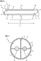
- FIG. 2 shows a transmission line 3 of a device for power transmission according to a second embodiment of the invention in a schematic longitudinal section.
- the conduit 3 may, for example, in cross-section similar to those in FIG. 1 be constructed line shown.
- the vacuum-insulated casing 13 has a non-corrugated cryostat inner wall 37 over a majority of a longitudinal extent of the conduit 3.
- the vacuum-insulated casing 13 is formed as a smooth, non-corrugated tube.
- the conduit may also have one or more corrugated segments 41, as in FIG FIG. 2 shown.
- the vacuum-insulated sheath has a corrugated profile, which increases mechanical flexibility of the conduit in terms of both elongation and compression rather than bending in that region.
- the cryostat inner wall 37 in these segments is lined on the inside with a smooth-walled tube insert 45.
- FIG. 3 shows a schematic schematic diagram of a device for DC transmission according to a third embodiment of the invention.
- This device 1 has two transmission lines 3a and 3b which, for example, similar to those in Figs Figures 1 and 2 shown can be constructed. In particular, these two lines can each be designed as a single-pole line, each with only one electrical conductor strand. By using both lines for power transmission a two-pole DC transmission is possible.
- the device for power transmission comprises a cooling device 7 with in this example two separate cooling units 18, in which the fluid coolant 11 is cooled down again after heating in the cooling channels of the lines.
- Each of the transmission lines has a total length 21 of at least 20 km.
- Each of the two lines 3a and 3b has at one of its two ends a device 17 for feeding cooled by one of the cooling units 18 down coolant in the radially inner region of the respective conduit.
- Each of the two lines 3a and 3b has only one such feeding device 17, for the line 3a it is arranged on the first end region 19a, and for the line 3b it is arranged on the opposite second end region 19b.
- the two lines In the axially inner region 23 and at the respective opposite ends of the line, the two lines have no such feeding devices.
- the fluid coolant 11 circulates in this example in a closed circuit through the coolant channels of the two lines 3a and 3b, the two cooling units 18 and the interposed coolant tubes 47 and feeders 17.
- the flow directions 27a and 27b of the coolant in the two lines are opposite thereto ,
- the thermal insulation of the radially inner regions 9 of the lines 3a and 3b ensures that their respective superconducting conductor elements are maintained over the entire longitudinal extent 21 of the lines at an operating temperature below the transition temperature of the superconductor.
- FIG. 4 shows a transmission line 3 for a device for power transmission according to a fourth embodiment of the invention in schematic cross section. Shown is a two-pole line 3 with two separate and mutually electrically insulated superconducting conductor elements 5a and 5b. Incidentally, the line 3 is similar to that in the Figures 1 and 2 shown unipolar lines.
- the two conductor elements 5a and 5b are also supported by web-like support members 39 against each other and against the vacuum-insulating sheath 13 here. As in FIG. 4 As shown, these support structures 39 can jointly support both conductor elements 5a and 5b. Alternatively, however, separate support structures may be provided for the two conductor elements.
- the conductor elements 5a and 5b are each surrounded by a dielectric insulating layer 31, which the conductor elements electrically against each other and against the outside Cable shield 29 isolated.
- This insulation layer 31 is in turn mainly formed by the coolant 11 flowing in the coolant channel 25 in cooperation with the electrically insulating support elements 39.
- Such a bipolar transmission line 3 can be used to transmit direct current in a device having only a single such line.
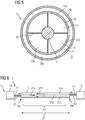
- FIG. 5 shows a schematic cross section of a transmission line 3 for a device for power transmission according to a fifth embodiment of the invention. Shown is a single-pole line with only one superconducting conductor element 5, similar as in the FIG. 1 , In contrast to this, the in FIG. 5 However, shown transmission line on two coolant channels, of which the first coolant channel 25a similar to the first embodiment between the conductor element 5 and cable shield 29 is arranged.
- the cable shield 29 is again designed as a cryostat inner wall 37a of an inner vacuum-insulated casing 13a. This is surrounded in the line according to the fifth embodiment by a second annular coolant channel 25b, which in turn is surrounded by an annular outer vacuum-insulated sheath 13b.
- This arrangement of two concentric coolant channels 25a and 25b ensures that the inner conductor element 5 is thermally insulated particularly well against the warm outer environment 15.
- the direction of flow in the two coolant channels 25a can thereby and 25b both equal and opposite.
- An opposite flow direction has the advantage that in this way a closed circuit of the coolant can be made possible over a single line in a simple manner.
- FIG. 6 shows a schematic schematic diagram of a device 1 for power transmission according to a sixth embodiment of the invention.
- This device has a single transmission line 3, which, for example, similar to in FIG. 5 can be constructed as a single-pole line with two concentric coolant channels 25a and 25b.
- the line can also be constructed as a two-pole line with two concentric coolant channels 25a and 25b.
- It may therefore be a transmission line, which has two inner conductor elements 5a and 5b, similar to in FIG FIG. 4 , but analogous to FIG. 5 of two concentric vacuum-insulated sheaths 13a and 13b and two concentric coolant channels 25a and 25b are surrounded.
- the transmission line has a first coolant channel 25a for transporting the coolant along a first flow direction 27a and a second coolant channel 25b for transporting the coolant along an opposite second flow direction.
- the device for power transmission 1 in turn has a cooling device 7, which in this example also comprises two cooling units 18 for cooling the fluid coolant 11 heated in the line interior. These two cooling units are arranged in the region of the two opposite line ends 19a and 19b.
- Each of these pipe ends has a feed device 17 for feeding coolant into an inner region of the pipe.
- a feed device 17 at the first end portion 19a is fluidly connected to the inner coolant channel 25a and the other feed device 17 at the second end portion 19b fluidly connected to the outer coolant channel 25b.
- FIG. 7 shows a schematic diagram of an alternative device 1 for DC transmission according to a seventh embodiment of the invention. Shown is a device with only a single line 3, which in turn can be configured either as a single-pole or two-pole line. Similar to in FIG. 6 Also, this line has two concentric coolant channels 25a and 25b. In contrast to the example of FIG. 6 However, here only at the first end portion 19a of the line, a feed device 17 for feeding coolant 11 is disposed in the interior of the conduit. In the example shown, the coolant is here first fed into the inner coolant channel 25 a, so that the cooler coolant flows closer to the inner conductor element 5 along. In principle, however, the sequence of the passage of the two coolant channels 25a and 25b can also be reversed.
- the fluidic connection can be as in FIG. 7 can be provided via an external coolant tube 47, it can alternatively be created in the interior of the conduit through an opening between the two coolant channels. It is only important that the two coolant channels are connected to each other in one of the feed device 17 opposite end portion.
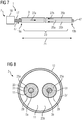
- FIG. 8 shows a schematic cross section of a conduit 3 according to an eighth embodiment of the invention. Shown is a two-pole line with two superconducting conductor elements 5a and 5b, similar to the example of FIG. 4 , In contrast to the fourth embodiment is here, however each of the two conductor elements 5a and 5b provided with its own cable shield 29 and arranged together with this within a common coolant channel 25b. This common coolant channel 25b is in turn surrounded by a common outer vacuum-insulated casing 13, which in this example, however, does not act as the primary cable screen, in other words not as the innermost cable screen. Between the individual conductor elements 5 and the respective cable shield 29, a separate dielectric insulation layer 31 with an annular cross section is arranged in each case.
- Each of the two insulation layers 31 comprises in this embodiment a multilayer arrangement 33 of a laminate of PPLP, which is embedded in each case in an inner coolant channel 25a.
- these two inner coolant channels also flows fluid coolant 11 and flows around the paper layers 33.
- the dielectric insulating layer 31 of the respective conductor strands is not nearly complete, but only partially formed from the flowing coolant. The remaining portion is given by the paper layers 33, which at the same time constitute a support structure for the respective inner conductor element 5a or 5b. Also with the transmission line after FIG.
- the flow direction of the coolant in the inner coolant channels 25a on the one hand and in the common outer coolant channel on the other hand may advantageously be opposite.
- a conduit can then be used in a device similar to the one shown in FIGS FIGS. 6 or 7 be used.
- FIG. 9 shows a schematic cross section of a single-pole transmission line 3 according to a ninth embodiment of the invention.
- the structure of this line 3 is very similar to that in the FIG. 8 However, it has only one superconducting conductor element 5, which is arranged radially in the middle of the line.
- the conductor element 5 is of a dielectric insulation layer 31, which is formed by cooperation of an arrangement of paper layers 33 and a flowing in an inner coolant passage 25 a to these paper layers 33 fluid coolant 11.
- a surrounding cable shield 29 is arranged, which in turn is surrounded by an outer coolant channel 25b and further outwardly by a vacuum-insulated sleeve 13.
- FIG. 10 shows a schematic cross section of a single-pole line 3 according to a tenth embodiment of the invention.
- the relative arrangement of conductor element 5, dielectric insulation layer 31 and cable shield 29 is similar to the ninth embodiment.
- the structure of the dielectric insulating layer 31 is realized similarly to the previous example by a combination of paper layers and flowing coolant.
- an additional coolant channel is arranged in the interior of the conductor element 5 here. This results in a total of three coolant channels, of which the first 25a is arranged in the center of the line, the second 25b is lined with paper layers 33 and the conductor element 5 radially surrounds and the third 25c is arranged radially between the cable shield 29 and vacuum-insulated sheath 13.
- the flow directions in the nested coolant channels can in turn advantageously alternate alternately.
- a similar structure as in FIG. 10 is basically also conceivable for a two-pole line, in which each conductor element is penetrated internally by an additional coolant channel.
- FIG. 11 shows a schematic diagram of a device for DC transmission according to an eleventh embodiment of the invention.
- this line may be generally one or two pole, and it may be one or more Have coolant channels.
- the cooling device 7 for cooling the at least one conductor element has at least one feed device 18 at an end region 19a of the line, but it is also possible for the feed device to be present at both end regions.
- Essential for this eleventh embodiment is that a net mass transfer of the coolant takes place along a longitudinal direction of the pipe.
- this is a substance transport along a first flow direction 27a from the first end region 19a to the second end region 19b of the line.
- a simultaneous mass transport in opposite flow direction 27b may also be present, but in the example shown this is less than the mass transfer in the first flow direction 27a.
- the device for DC transmission can be used simultaneously for the transmission of coolant along the line 3.
- the first flow direction 27a which is decisive for mass transport, can be the same as the transmission direction 49 of the electrical energy. This is particularly advantageous for transporting electrical energy as well as hydrogen produced by electrolysis to a different location from a location where much energy is available.
- FIG. 12 shows a schematic cross section of another transmission line 3 according to a twelfth embodiment of the invention. Shown is a two-pole line with two conductor elements 5a and 5b which is similar to that in FIG. 5 two concentric vacuum-insulated sheaths 13a and 13b, wherein within the inner shell 13a, an inner coolant channel 25a and between the two shells an outer coolant channel 25b is arranged.
- the two conductor elements are each electrically insulated from their respective innermost conductor shields 29 by solid-state dielectrics as the insulation layer 31.
- the inner coolant channel 25a surrounds these two so isolated and shielded cable strands together. Even with such a structure can by the nested arrangement of Cooling channels and vacuum-insulated sheaths a high thermal and electrical shielding of the conductor elements can be achieved.
Landscapes
- Superconductors And Manufacturing Methods Therefor (AREA)
- Containers, Films, And Cooling For Superconductive Devices (AREA)
Claims (11)
- Dispositif (1) de transport de courant continu, comprenant- une ligne (3) supraconductrice de transport ayant au moins un élément (5) conducteur supraconducteur et- un dispositif (7) de refroidissement pour refroidir une partie (9) intérieure radialement de la ligne (3) de transport à l'aide d'un fluide (11) de refroidissement à une température inférieure au point de changement brusque de la conductivité de l'élément (5) conducteur supraconducteur,- dans lequel la ligne (3) supraconductrice de transport a une gaine (13) à isolation par le vide, pour séparer thermiquement la partie (9) intérieure de la ligne (3) de transport d'un environnement (15) extérieur plus chaud,- dans lequel le dispositif (7) de refroidissement comprend au moins un dispositif (17) d'injection, pour injecter du fluide (11) de refroidissement à une partie (19a) d'extrémité de la ligne (3) de transport dans la partie (9) intérieure radialement de la ligne (3) de transport,- dans lequel la ligne (3) de transport est, pour une étendue (21) longitudinale axiale d'au moins 20 km, sans dispositif, disposé à l'intérieur axialement, d'injection de fluide de refroidissement- dans lequel la ligne (3) de transport a un blindage (29) conducteur de l'électricité, qui entoure annulairement l'élément (5) conducteur supraconducteur et- une couche (31) annulaire diélectrique isolante entre l'élément (5) conducteur supraconducteur et le blindage (29) et- au moins un canal (25a, 25b) pour du fluide de refroidissement entourant annulairement l'élément (5) conducteur supraconducteur, afin de transporter du fluide (11) de refroidissement suivant une direction longitudinale de la ligne (3) de transport caractérisé en ce que- la couche (31) diélectrique isolante est formée essentiellement par le canal annulaire pour du fluide de refroidissement empli du fluide du fluide de refroidissement et- il y a des segments axiaux continus radialement et/ou des segments azimutaux de la ligne de transport, dans lesquels la couche diélectrique isolante est formée complètement par du fluide de refroidissement.
- Dispositif (1) suivant la revendication 1, dans lequel la couche (31) diélectrique isolante a une rigidité diélectrique de moins de 20 kV/mm.
- Dispositif (1) suivant l'une des revendications précédentes, dans lequel la couche (3) diélectrique isolante a au moins une couche d'un papier (33) noyé dans du fluide (11) de refroidissement.
- Dispositif (1) suivant l'une des revendications précédentes, dans lequel le fluide (11) de refroidissement passe à l'intérieur de la ligne (3) de transport, au moins sur une partie prépondérante de l'étendue longitudinale de la ligne de transport, à l'intérieur d'un tube (35) à paroi lisse.
- Dispositif (1) suivant l'une des revendications précédentes, dans lequel l'élément (5) conducteur supraconducteur comprend un matériau supraconducteur à haute température.
- Dispositif (1) suivant la revendication 5, dans lequel le matériau supraconducteur à haute température comprend du diborure de magnésium.
- Dispositif (1) suivant l'une des revendications précédentes, dans lequel le dispositif (7) de refroidissement a un dispositif (17) d'injection de fluide (11) de refroidissement, seulement à l'une des parties (19a) d'extrémité de la ligne (3) de transport.
- Dispositif (1) suivant l'une des revendications précédentes, dans lequel la ligne de transport a deux canaux (25a, 25b) séparés fluidiquement pour du fluide de refroidissement pour le transport du fluide (11) de refroidissement dans des sens (27a, 27b) contraires.
- Dispositif (1) suivant l'une des revendications précédentes, dans lequel la ligne (3) de transport est conformée en ligne bipolaire ayant deux éléments conducteurs supraconducteurs isolés électriquement l'un de l'autre à l'intérieur d'une gaine (13) commune à isolation par le vide.
- Dispositif (1) suivant l'une des revendications précédentes, caractérisé en ce que la ligne (3) de transport a deux canaux (25a, 25b) pour du fluide de refroidissement s'étendant coaxialement l'un à l'autre.
- Dispositif (1) suivant l'une des revendications précédentes, dans lequel le fluide (11) de refroidissement comprend de l'azote, de l'hydrogène, de l'hélium et/ou du néon.
Applications Claiming Priority (2)
| Application Number | Priority Date | Filing Date | Title |
|---|---|---|---|
| DE102015209432.4A DE102015209432A1 (de) | 2015-05-22 | 2015-05-22 | Vorrichtung zur Gleichstromübertragung und Kühlverfahren |
| PCT/EP2016/059184 WO2016188688A1 (fr) | 2015-05-22 | 2016-04-25 | Dispositif de transmission de courant continu et procédé de refroidissement |
Publications (2)
| Publication Number | Publication Date |
|---|---|
| EP3281211A1 EP3281211A1 (fr) | 2018-02-14 |
| EP3281211B1 true EP3281211B1 (fr) | 2019-06-05 |
Family
ID=55862767
Family Applications (1)
| Application Number | Title | Priority Date | Filing Date |
|---|---|---|---|
| EP16719833.2A Active EP3281211B1 (fr) | 2015-05-22 | 2016-04-25 | Dispositif de transmission de courant continu |
Country Status (5)
| Country | Link |
|---|---|
| US (1) | US11430584B2 (fr) |
| EP (1) | EP3281211B1 (fr) |
| CN (1) | CN107646134B (fr) |
| DE (1) | DE102015209432A1 (fr) |
| WO (1) | WO2016188688A1 (fr) |
Cited By (1)
| Publication number | Priority date | Publication date | Assignee | Title |
|---|---|---|---|---|
| EP4608115A1 (fr) | 2024-02-23 | 2025-08-27 | Ulrich Neumann | Agencement de sections adjacentes de supports de conduites de types différents |
Families Citing this family (15)
| Publication number | Priority date | Publication date | Assignee | Title |
|---|---|---|---|---|
| DE102015209432A1 (de) | 2015-05-22 | 2016-11-24 | Siemens Aktiengesellschaft | Vorrichtung zur Gleichstromübertragung und Kühlverfahren |
| US10509448B2 (en) * | 2015-09-24 | 2019-12-17 | Rambus Inc. | Thermal clamp for cyrogenic digital systems |
| DE102017206915A1 (de) * | 2017-04-25 | 2018-10-25 | Siemens Aktiengesellschaft | Vorrichtung und Verfahren zur Gleichstromübertragung mit hoher Nennleistung |
| IT202000002959A1 (it) | 2020-02-14 | 2021-08-14 | Danieli Automation Spa | Apparato di alimentazione elettrica per un dispositivo utilizzatore a potenza elevata |
| PL435036A1 (pl) * | 2020-08-20 | 2022-02-21 | General Electric Company Polska Spółka Z Ograniczoną Odpowiedzialnością | Konstrukcja połączeń dla zespołu generatora |
| CA3197746A1 (fr) * | 2020-11-18 | 2022-05-27 | Stephen Paul Ashworth | Lignes de transport supraconductrices suspendues |
| EP4248467A1 (fr) | 2020-11-18 | 2023-09-27 | Veir, Inc. | Systèmes conducteurs pour lignes de transmission suspendues ou souterraines |
| KR20230129393A (ko) | 2020-11-18 | 2023-09-08 | 베어, 인크. | 초전도 전력 전송 선로들의 냉각을 위한 시스템들 및 방법들 |
| US20260112520A1 (en) * | 2021-07-22 | 2026-04-23 | Chevron U.S.A. Inc. | High voltage submarine cable systems |
| EP4304026A1 (fr) * | 2022-07-08 | 2024-01-10 | NKT HV Cables AB | Système en mer comprenant un câble électrique sous-marin dynamique |
| EP4350717A1 (fr) * | 2022-10-04 | 2024-04-10 | NKT HV Cables AB | Câble d'alimentation sous-marin dynamique à barrière d'eau métallique ondulée et lisse |
| US12548693B2 (en) * | 2023-07-19 | 2026-02-10 | CERN—European Organization for Nuclear Research | Cryogenic link |
| US20250035872A1 (en) * | 2023-07-25 | 2025-01-30 | Subcom, Llc | Dual metal conductor undersea cable |
| KR102721398B1 (ko) * | 2024-03-22 | 2024-10-24 | 한국그린전력(주) | 위크튜브 버스바 |
| KR102807592B1 (ko) * | 2024-06-12 | 2025-05-19 | 한국그린전력 주식회사 | 마이크로라인 버스바 |
Family Cites Families (16)
| Publication number | Priority date | Publication date | Assignee | Title |
|---|---|---|---|---|
| DE2043445A1 (de) * | 1970-09-02 | 1972-03-09 | Kabel Metallwerke Ghh | Anordnung zur Halterung eines oder mehrerer supraleitfähiger Leiterstrange im Innern eines tiefstgekuhlten Kabels |
| GB9511464D0 (en) * | 1995-06-07 | 1995-08-02 | Bicc Plc | Electric conductors and cables |
| EP0807938A1 (fr) * | 1996-05-14 | 1997-11-19 | FINMECCANICA S.p.A. AZIENDA ANSALDO | Structure d'un conduit pour contenir et pour l'isolation thermique de supraconducteurs électriques refroidis avec un fluide cryogénique |
| JP2004523197A (ja) | 2001-03-12 | 2004-07-29 | エヌケイテイ ケーブルズ アルテラ アクティーゼルスカブ | 補償された電力ケーブルセクションを含むネットワーク |
| JP4162191B2 (ja) | 2002-04-05 | 2008-10-08 | 住友電気工業株式会社 | 超電導ケーブル線路の冷却方法 |
| US7237317B2 (en) * | 2003-05-20 | 2007-07-03 | Nexans | Process for producing a superconducting cable |
| US7943852B2 (en) * | 2005-03-14 | 2011-05-17 | Sumitomo Electric Industries, Ltd. | Superconducting cable |
| US20080190646A1 (en) * | 2007-02-09 | 2008-08-14 | Folts Douglas C | Parallel connected hts fcl device |
| JP5203642B2 (ja) | 2007-06-29 | 2013-06-05 | 株式会社前川製作所 | 超電導送電ケーブル、及びそのシステム |
| US8478374B2 (en) * | 2008-03-28 | 2013-07-02 | American Superconductor Corporation | Superconducting cable assembly and method of assembly |
| EP2418747B1 (fr) | 2010-08-13 | 2015-11-25 | Nexans | Agencement de liaisons électriques conductrices de deux unités électriques |
| JP2013140764A (ja) * | 2011-12-06 | 2013-07-18 | Sumitomo Electric Ind Ltd | 超電導ケーブル、超電導ケーブル線路、超電導ケーブルの布設方法、及び超電導ケーブル線路の運転方法 |
| EP2685469B1 (fr) | 2012-07-11 | 2017-05-03 | Nexans | Agencement doté d'au moins un câble supraconducteur |
| DK2693584T3 (en) | 2012-08-03 | 2018-03-05 | Nexans | Arrangement with at least one superconducting cable |
| EP2698794B8 (fr) * | 2012-08-14 | 2017-08-30 | Nexans | Agencement doté d'au moins un câble supraconducteur |
| DE102015209432A1 (de) | 2015-05-22 | 2016-11-24 | Siemens Aktiengesellschaft | Vorrichtung zur Gleichstromübertragung und Kühlverfahren |
-
2015
- 2015-05-22 DE DE102015209432.4A patent/DE102015209432A1/de not_active Withdrawn
-
2016
- 2016-04-25 CN CN201680029672.2A patent/CN107646134B/zh active Active
- 2016-04-25 EP EP16719833.2A patent/EP3281211B1/fr active Active
- 2016-04-25 WO PCT/EP2016/059184 patent/WO2016188688A1/fr not_active Ceased
- 2016-04-25 US US15/574,885 patent/US11430584B2/en active Active
Non-Patent Citations (1)
| Title |
|---|
| None * |
Cited By (1)
| Publication number | Priority date | Publication date | Assignee | Title |
|---|---|---|---|---|
| EP4608115A1 (fr) | 2024-02-23 | 2025-08-27 | Ulrich Neumann | Agencement de sections adjacentes de supports de conduites de types différents |
Also Published As
| Publication number | Publication date |
|---|---|
| CN107646134B (zh) | 2019-07-05 |
| CN107646134A (zh) | 2018-01-30 |
| WO2016188688A1 (fr) | 2016-12-01 |
| DE102015209432A1 (de) | 2016-11-24 |
| US11430584B2 (en) | 2022-08-30 |
| EP3281211A1 (fr) | 2018-02-14 |
| US20180166188A1 (en) | 2018-06-14 |
Similar Documents
| Publication | Publication Date | Title |
|---|---|---|
| EP3281211B1 (fr) | Dispositif de transmission de courant continu | |
| DE102015220301A1 (de) | Energieübertragungsvorrichtung für ein Fahrzeug | |
| DE1640750B1 (de) | Supraleitendes wechselstromkabel | |
| DE112016003022T5 (de) | Supraleitender Draht | |
| EP2418747B1 (fr) | Agencement de liaisons électriques conductrices de deux unités électriques | |
| DE2157125C3 (de) | Stromzuführung für elektrische Einrichtungen mit auf Tieftemperatur gekühlten Leitern | |
| EP2202762A1 (fr) | Dispositif comprenant un câble supraconducteur | |
| DE102018206564A1 (de) | Supraleitende elektrische Spuleneinrichtung sowie Rotor mit Spuleneinrichtung | |
| EP2426676A1 (fr) | Agencement doté d'au moins un câble supraconducteur | |
| EP2634779A1 (fr) | Système doté d'un élément de transmission électrique supraconducteur triphasé | |
| EP2770514A1 (fr) | Procédé de refroidissement d'un câble supraconducteur | |
| DE3811051A1 (de) | Supraleitendes kabel mit oxidkeramischem hochtemperatursupraleiter-material | |
| DE202019003381U1 (de) | Muffe für ein supraleitfähiges Kabel und supraleitfähiges Kabel mit Anschluss für eine Zwischenkühlung | |
| DE2163270B1 (de) | Stromzuführung fur elektrische Ein richtungen mit auf Tieftemperatur ge kühlten Leitern | |
| DE2249560A1 (de) | Endverschluss fuer tieftemperaturkabel | |
| DE2317013B2 (de) | Wassergekühltes Hochspannungsenergiekabel | |
| DE102018213598A1 (de) | Supraleitende Stromzuführung | |
| DE69830060T2 (de) | Hochtemperatur - supraleitendes kabel und verfahren zu seiner herstellung | |
| DE3811050C2 (fr) | ||
| DE1665721A1 (de) | Supraleitendes Starkstromkabel | |
| DE102017206915A1 (de) | Vorrichtung und Verfahren zur Gleichstromübertragung mit hoher Nennleistung | |
| DE1640750C (de) | Supraleitendes Wechselstromkabel | |
| DE2252924C3 (de) | Wassergekühltes Hochspannungskabel | |
| DE2252926A1 (de) | Oelkabel | |
| DE2825937A1 (de) | Abstandswendel fuer koaxiale rohrsysteme |
Legal Events
| Date | Code | Title | Description |
|---|---|---|---|
| STAA | Information on the status of an ep patent application or granted ep patent |
Free format text: STATUS: THE INTERNATIONAL PUBLICATION HAS BEEN MADE |
|
| PUAI | Public reference made under article 153(3) epc to a published international application that has entered the european phase |
Free format text: ORIGINAL CODE: 0009012 |
|
| STAA | Information on the status of an ep patent application or granted ep patent |
Free format text: STATUS: REQUEST FOR EXAMINATION WAS MADE |
|
| 17P | Request for examination filed |
Effective date: 20171109 |
|
| AK | Designated contracting states |
Kind code of ref document: A1 Designated state(s): AL AT BE BG CH CY CZ DE DK EE ES FI FR GB GR HR HU IE IS IT LI LT LU LV MC MK MT NL NO PL PT RO RS SE SI SK SM TR |
|
| AX | Request for extension of the european patent |
Extension state: BA ME |
|
| DAV | Request for validation of the european patent (deleted) | ||
| DAX | Request for extension of the european patent (deleted) | ||
| GRAP | Despatch of communication of intention to grant a patent |
Free format text: ORIGINAL CODE: EPIDOSNIGR1 |
|
| STAA | Information on the status of an ep patent application or granted ep patent |
Free format text: STATUS: GRANT OF PATENT IS INTENDED |
|
| INTG | Intention to grant announced |
Effective date: 20190207 |
|
| GRAS | Grant fee paid |
Free format text: ORIGINAL CODE: EPIDOSNIGR3 |
|
| GRAA | (expected) grant |
Free format text: ORIGINAL CODE: 0009210 |
|
| STAA | Information on the status of an ep patent application or granted ep patent |
Free format text: STATUS: THE PATENT HAS BEEN GRANTED |
|
| AK | Designated contracting states |
Kind code of ref document: B1 Designated state(s): AL AT BE BG CH CY CZ DE DK EE ES FI FR GB GR HR HU IE IS IT LI LT LU LV MC MK MT NL NO PL PT RO RS SE SI SK SM TR |
|
| REG | Reference to a national code |
Ref country code: GB Ref legal event code: FG4D Free format text: NOT ENGLISH |
|
| REG | Reference to a national code |
Ref country code: CH Ref legal event code: EP |
|
| REG | Reference to a national code |
Ref country code: AT Ref legal event code: REF Ref document number: 1140815 Country of ref document: AT Kind code of ref document: T Effective date: 20190615 |
|
| REG | Reference to a national code |
Ref country code: DE Ref legal event code: R096 Ref document number: 502016004924 Country of ref document: DE |
|
| REG | Reference to a national code |
Ref country code: IE Ref legal event code: FG4D Free format text: LANGUAGE OF EP DOCUMENT: GERMAN |
|
| REG | Reference to a national code |
Ref country code: NL Ref legal event code: FP |
|
| REG | Reference to a national code |
Ref country code: LT Ref legal event code: MG4D |
|
| PG25 | Lapsed in a contracting state [announced via postgrant information from national office to epo] |
Ref country code: ES Free format text: LAPSE BECAUSE OF FAILURE TO SUBMIT A TRANSLATION OF THE DESCRIPTION OR TO PAY THE FEE WITHIN THE PRESCRIBED TIME-LIMIT Effective date: 20190605 Ref country code: AL Free format text: LAPSE BECAUSE OF FAILURE TO SUBMIT A TRANSLATION OF THE DESCRIPTION OR TO PAY THE FEE WITHIN THE PRESCRIBED TIME-LIMIT Effective date: 20190605 Ref country code: LT Free format text: LAPSE BECAUSE OF FAILURE TO SUBMIT A TRANSLATION OF THE DESCRIPTION OR TO PAY THE FEE WITHIN THE PRESCRIBED TIME-LIMIT Effective date: 20190605 Ref country code: NO Free format text: LAPSE BECAUSE OF FAILURE TO SUBMIT A TRANSLATION OF THE DESCRIPTION OR TO PAY THE FEE WITHIN THE PRESCRIBED TIME-LIMIT Effective date: 20190905 Ref country code: FI Free format text: LAPSE BECAUSE OF FAILURE TO SUBMIT A TRANSLATION OF THE DESCRIPTION OR TO PAY THE FEE WITHIN THE PRESCRIBED TIME-LIMIT Effective date: 20190605 Ref country code: HR Free format text: LAPSE BECAUSE OF FAILURE TO SUBMIT A TRANSLATION OF THE DESCRIPTION OR TO PAY THE FEE WITHIN THE PRESCRIBED TIME-LIMIT Effective date: 20190605 Ref country code: SE Free format text: LAPSE BECAUSE OF FAILURE TO SUBMIT A TRANSLATION OF THE DESCRIPTION OR TO PAY THE FEE WITHIN THE PRESCRIBED TIME-LIMIT Effective date: 20190605 |
|
| PG25 | Lapsed in a contracting state [announced via postgrant information from national office to epo] |
Ref country code: RS Free format text: LAPSE BECAUSE OF FAILURE TO SUBMIT A TRANSLATION OF THE DESCRIPTION OR TO PAY THE FEE WITHIN THE PRESCRIBED TIME-LIMIT Effective date: 20190605 Ref country code: LV Free format text: LAPSE BECAUSE OF FAILURE TO SUBMIT A TRANSLATION OF THE DESCRIPTION OR TO PAY THE FEE WITHIN THE PRESCRIBED TIME-LIMIT Effective date: 20190605 Ref country code: GR Free format text: LAPSE BECAUSE OF FAILURE TO SUBMIT A TRANSLATION OF THE DESCRIPTION OR TO PAY THE FEE WITHIN THE PRESCRIBED TIME-LIMIT Effective date: 20190906 Ref country code: BG Free format text: LAPSE BECAUSE OF FAILURE TO SUBMIT A TRANSLATION OF THE DESCRIPTION OR TO PAY THE FEE WITHIN THE PRESCRIBED TIME-LIMIT Effective date: 20190905 |
|
| PG25 | Lapsed in a contracting state [announced via postgrant information from national office to epo] |
Ref country code: PT Free format text: LAPSE BECAUSE OF FAILURE TO SUBMIT A TRANSLATION OF THE DESCRIPTION OR TO PAY THE FEE WITHIN THE PRESCRIBED TIME-LIMIT Effective date: 20191007 Ref country code: SK Free format text: LAPSE BECAUSE OF FAILURE TO SUBMIT A TRANSLATION OF THE DESCRIPTION OR TO PAY THE FEE WITHIN THE PRESCRIBED TIME-LIMIT Effective date: 20190605 Ref country code: CZ Free format text: LAPSE BECAUSE OF FAILURE TO SUBMIT A TRANSLATION OF THE DESCRIPTION OR TO PAY THE FEE WITHIN THE PRESCRIBED TIME-LIMIT Effective date: 20190605 Ref country code: RO Free format text: LAPSE BECAUSE OF FAILURE TO SUBMIT A TRANSLATION OF THE DESCRIPTION OR TO PAY THE FEE WITHIN THE PRESCRIBED TIME-LIMIT Effective date: 20190605 Ref country code: EE Free format text: LAPSE BECAUSE OF FAILURE TO SUBMIT A TRANSLATION OF THE DESCRIPTION OR TO PAY THE FEE WITHIN THE PRESCRIBED TIME-LIMIT Effective date: 20190605 |
|
| PG25 | Lapsed in a contracting state [announced via postgrant information from national office to epo] |
Ref country code: SM Free format text: LAPSE BECAUSE OF FAILURE TO SUBMIT A TRANSLATION OF THE DESCRIPTION OR TO PAY THE FEE WITHIN THE PRESCRIBED TIME-LIMIT Effective date: 20190605 Ref country code: IS Free format text: LAPSE BECAUSE OF FAILURE TO SUBMIT A TRANSLATION OF THE DESCRIPTION OR TO PAY THE FEE WITHIN THE PRESCRIBED TIME-LIMIT Effective date: 20191005 |
|
| REG | Reference to a national code |
Ref country code: DE Ref legal event code: R097 Ref document number: 502016004924 Country of ref document: DE |
|
| PLBE | No opposition filed within time limit |
Free format text: ORIGINAL CODE: 0009261 |
|
| STAA | Information on the status of an ep patent application or granted ep patent |
Free format text: STATUS: NO OPPOSITION FILED WITHIN TIME LIMIT |
|
| PG25 | Lapsed in a contracting state [announced via postgrant information from national office to epo] |
Ref country code: PL Free format text: LAPSE BECAUSE OF FAILURE TO SUBMIT A TRANSLATION OF THE DESCRIPTION OR TO PAY THE FEE WITHIN THE PRESCRIBED TIME-LIMIT Effective date: 20190605 Ref country code: DK Free format text: LAPSE BECAUSE OF FAILURE TO SUBMIT A TRANSLATION OF THE DESCRIPTION OR TO PAY THE FEE WITHIN THE PRESCRIBED TIME-LIMIT Effective date: 20190605 |
|
| 26N | No opposition filed |
Effective date: 20200306 |
|
| PG25 | Lapsed in a contracting state [announced via postgrant information from national office to epo] |
Ref country code: SI Free format text: LAPSE BECAUSE OF FAILURE TO SUBMIT A TRANSLATION OF THE DESCRIPTION OR TO PAY THE FEE WITHIN THE PRESCRIBED TIME-LIMIT Effective date: 20190605 |
|
| PG25 | Lapsed in a contracting state [announced via postgrant information from national office to epo] |
Ref country code: MC Free format text: LAPSE BECAUSE OF FAILURE TO SUBMIT A TRANSLATION OF THE DESCRIPTION OR TO PAY THE FEE WITHIN THE PRESCRIBED TIME-LIMIT Effective date: 20190605 |
|
| REG | Reference to a national code |
Ref country code: CH Ref legal event code: PL |
|
| REG | Reference to a national code |
Ref country code: DE Ref legal event code: R081 Ref document number: 502016004924 Country of ref document: DE Owner name: SIEMENS ENERGY GLOBAL GMBH & CO. KG, DE Free format text: FORMER OWNER: SIEMENS AKTIENGESELLSCHAFT, 80333 MUENCHEN, DE |
|
| PG25 | Lapsed in a contracting state [announced via postgrant information from national office to epo] |
Ref country code: LI Free format text: LAPSE BECAUSE OF NON-PAYMENT OF DUE FEES Effective date: 20200430 Ref country code: CH Free format text: LAPSE BECAUSE OF NON-PAYMENT OF DUE FEES Effective date: 20200430 Ref country code: LU Free format text: LAPSE BECAUSE OF NON-PAYMENT OF DUE FEES Effective date: 20200425 |
|
| REG | Reference to a national code |
Ref country code: BE Ref legal event code: MM Effective date: 20200430 |
|
| PG25 | Lapsed in a contracting state [announced via postgrant information from national office to epo] |
Ref country code: BE Free format text: LAPSE BECAUSE OF NON-PAYMENT OF DUE FEES Effective date: 20200430 |
|
| PG25 | Lapsed in a contracting state [announced via postgrant information from national office to epo] |
Ref country code: IE Free format text: LAPSE BECAUSE OF NON-PAYMENT OF DUE FEES Effective date: 20200425 |
|
| PG25 | Lapsed in a contracting state [announced via postgrant information from national office to epo] |
Ref country code: MT Free format text: LAPSE BECAUSE OF FAILURE TO SUBMIT A TRANSLATION OF THE DESCRIPTION OR TO PAY THE FEE WITHIN THE PRESCRIBED TIME-LIMIT Effective date: 20190605 Ref country code: CY Free format text: LAPSE BECAUSE OF FAILURE TO SUBMIT A TRANSLATION OF THE DESCRIPTION OR TO PAY THE FEE WITHIN THE PRESCRIBED TIME-LIMIT Effective date: 20190605 |
|
| REG | Reference to a national code |
Ref country code: AT Ref legal event code: MM01 Ref document number: 1140815 Country of ref document: AT Kind code of ref document: T Effective date: 20210425 |
|
| PG25 | Lapsed in a contracting state [announced via postgrant information from national office to epo] |
Ref country code: MK Free format text: LAPSE BECAUSE OF FAILURE TO SUBMIT A TRANSLATION OF THE DESCRIPTION OR TO PAY THE FEE WITHIN THE PRESCRIBED TIME-LIMIT Effective date: 20190605 |
|
| PG25 | Lapsed in a contracting state [announced via postgrant information from national office to epo] |
Ref country code: AT Free format text: LAPSE BECAUSE OF NON-PAYMENT OF DUE FEES Effective date: 20210425 |
|
| REG | Reference to a national code |
Ref country code: GB Ref legal event code: 732E Free format text: REGISTERED BETWEEN 20220901 AND 20220907 |
|
| REG | Reference to a national code |
Ref country code: NL Ref legal event code: PD Owner name: SIEMENS ENERGY GLOBAL GMBH & CO. KG; DE Free format text: DETAILS ASSIGNMENT: CHANGE OF OWNER(S), ASSIGNMENT; FORMER OWNER NAME: SIEMENS AKTIENGESELLSCHAFT Effective date: 20221220 |
|
| P01 | Opt-out of the competence of the unified patent court (upc) registered |
Effective date: 20231222 |
|
| PGFP | Annual fee paid to national office [announced via postgrant information from national office to epo] |
Ref country code: NL Payment date: 20250424 Year of fee payment: 10 |
|
| PGFP | Annual fee paid to national office [announced via postgrant information from national office to epo] |
Ref country code: DE Payment date: 20250428 Year of fee payment: 10 |
|
| PGFP | Annual fee paid to national office [announced via postgrant information from national office to epo] |
Ref country code: IT Payment date: 20250422 Year of fee payment: 10 |
|
| PGFP | Annual fee paid to national office [announced via postgrant information from national office to epo] |
Ref country code: FR Payment date: 20250424 Year of fee payment: 10 |
|
| PGFP | Annual fee paid to national office [announced via postgrant information from national office to epo] |
Ref country code: TR Payment date: 20250408 Year of fee payment: 10 |
|
| PGFP | Annual fee paid to national office [announced via postgrant information from national office to epo] |
Ref country code: GB Payment date: 20260323 Year of fee payment: 11 |