EP3281263B1 - Zündkerze - Google Patents
Zündkerze Download PDFInfo
- Publication number
- EP3281263B1 EP3281263B1 EP17713153.9A EP17713153A EP3281263B1 EP 3281263 B1 EP3281263 B1 EP 3281263B1 EP 17713153 A EP17713153 A EP 17713153A EP 3281263 B1 EP3281263 B1 EP 3281263B1
- Authority
- EP
- European Patent Office
- Prior art keywords
- spark plug
- housing portion
- insulator
- rear housing
- housing part
- Prior art date
- Legal status (The legal status is an assumption and is not a legal conclusion. Google has not performed a legal analysis and makes no representation as to the accuracy of the status listed.)
- Active
Links
Images
Classifications
-
- H—ELECTRICITY
- H01—ELECTRIC ELEMENTS
- H01T—SPARK GAPS; OVERVOLTAGE ARRESTERS USING SPARK GAPS; SPARKING PLUGS; CORONA DEVICES; GENERATING IONS TO BE INTRODUCED INTO NON-ENCLOSED GASES
- H01T13/00—Sparking plugs
- H01T13/54—Sparking plugs having electrodes arranged in a partly-enclosed ignition chamber
-
- H—ELECTRICITY
- H01—ELECTRIC ELEMENTS
- H01T—SPARK GAPS; OVERVOLTAGE ARRESTERS USING SPARK GAPS; SPARKING PLUGS; CORONA DEVICES; GENERATING IONS TO BE INTRODUCED INTO NON-ENCLOSED GASES
- H01T13/00—Sparking plugs
- H01T13/02—Details
- H01T13/16—Means for dissipating heat
-
- H—ELECTRICITY
- H01—ELECTRIC ELEMENTS
- H01T—SPARK GAPS; OVERVOLTAGE ARRESTERS USING SPARK GAPS; SPARKING PLUGS; CORONA DEVICES; GENERATING IONS TO BE INTRODUCED INTO NON-ENCLOSED GASES
- H01T13/00—Sparking plugs
- H01T13/20—Sparking plugs characterised by features of the electrodes or insulation
- H01T13/32—Sparking plugs characterised by features of the electrodes or insulation characterised by features of the earthed electrode
Definitions
- the present invention relates to a spark plug, in particular a prechamber spark plug, with a housing, an ignition electrode and a ground electrode, wherein the ignition electrode can be subjected to an electrical voltage via a supply line and wherein the supply line runs at least partially within an insulator.
- Spark plugs of the type in question have been known from practice for years. In an internal combustion engine, these serve to ignite the compressed fuel-air mixture in the combustion chamber of the cylinder. A high-voltage spark ignites the compressed fuel-air mixture on the spark plug.
- a spark plug comprising an ignition electrode and a ground electrode.
- the spark plug has a housing which is formed from a housing head and a holder and which accommodates part of an insulator.
- the insulator encloses a supply line which is used to apply electrical voltage to the ignition electrode.
- the housing head is made of steel and connected to the holder made of a nickel-iron alloy via a welded seam.
- the nickel-iron alloy has a coefficient of thermal expansion which is lower than the coefficient of thermal expansion of the insulator, so that the preload with which the insulator is arranged in the housing also increases with increasing temperature.
- the problem with the known spark plug is that it heats up too much during operation, which has a negative effect on the areas relevant to the service life of the spark plug, such as the electrodes and any interference suppression resistor that may be present. In extreme cases, glow ignitions or knocking burns can occur in the area of the spark plug so that the function of the engine is severely impaired.
- the present invention is therefore based on the object of designing and developing a spark plug of the type mentioned at the outset in such a way that overheating of the spark plug is avoided with structurally simple means.
- the above object is achieved by the features of claim 1.
- the spark plug in question is characterized in that at least one discharge area of the housing is made from a material with a thermal conductivity of over 150 W / mK.
- the underlying object can be achieved in an incredibly simple manner by arranging a discharge area on the housing.
- the dissipation area serves to dissipate the heat of combustion entered into the spark plug to the environment.
- the dissipation area is made of a material with a thermal conductivity of over 150 W / mK, so that a sufficiently high dissipation of heat is ensured and can advantageously connect directly to the ground electrode.
- This simple design measure reliably prevents overheating of the spark plug, in particular of the areas relevant to the service life of the spark plug. This can significantly reduce the occurrence of glow ignitions or knocking burns in the area of the spark plug.
- the discharge area has a thermal conductivity that is higher than the thermal conductivity of steel, which is the material known from the prior art for manufacturing the housing. Contrary to a prejudice of experts, it has been shown that materials with a higher thermal conductivity are suitable for the production of at least one area of the housing of a spark plug despite the higher coefficient of thermal expansion usually associated therewith.
- the specified thermal conductivity relates in particular to the temperature range relevant for a spark plug.
- the thermal conductivity is specified in the units of watts per meter and Kelvin.
- the discharge area can advantageously have a thermal conductivity of over 200 W / mK. With such a high thermal conductivity, overheating of the spark plug is almost impossible, so that the problems caused by overheating are effectively avoided.
- the discharge area can be made of copper, a copper alloy or a copper-based alloy comprising proportions of nickel and / or beryllium.
- the housing can advantageously be designed in one piece. As a result, a particularly simple construction of the spark plug is realized, so that it is inexpensive to manufacture.
- the entire housing can be designed as a discharge area.
- the housing has a front housing part and a rear housing part, and is thus constructed in two parts.
- the front housing part can advantageously be connected to the rear housing part via a weld seam.
- the weld seam can be produced, for example, via tungsten inert gas welding (TIG), plasma welding, electron welding or laser welding.
- the dissipation area can be implemented by the front housing part, which is thus made entirely of a material with a thermal conductivity of over 150 W / mK. This further improves the dissipation of process heat and simplifies the design of the spark plug.
- the front housing part is particularly suitable for one of the above welding processes due to its high thermal conductivity.
- the discharge area can be formed by the rear housing part.
- the rear housing part can have a coefficient of thermal expansion that is less than or equal to is equal to the coefficient of thermal expansion of the insulator.
- the rear housing part can consist of a nickel-iron alloy, for example Ni Co 29/18 with a coefficient of thermal expansion ⁇ of 5 • 10 -6 1 / K to 8 • 10 -6 1 / K), the insulator from a Ceramic, in particular aluminum oxide (coefficient of thermal expansion ⁇ of approx. 8.5 • 10 -6 1 / K) or aluminum nitride can be produced.
- the outside of the housing can advantageously be conical at least in some areas and / or have a thread. In a particularly advantageous manner, this can be a correspondingly designed front housing part. This ensures a secure connection and seal between the spark plug and cylinder.
- a particularly secure connection between the housing and the insulator can be implemented in that the housing engages behind the insulator and holds it in the housing under prestress, preferably pressing it against a sealing ring, in particular made of copper.
- the rear housing part can engage behind the insulator and hold it in the housing under prestress.
- a special combinatorial effect can be achieved in that the front housing part is designed as a discharge area and is connected to the rear housing part via a weld, the rear housing part having a coefficient of thermal expansion that is less than or equal to the coefficient of thermal expansion of the insulation body.
- the heat from the spark plug can be dissipated through the front housing part, the rear housing part, due to its low coefficient of thermal expansion, holding the insulator in the housing with a higher preload the higher the temperature rises. This compensates for a higher coefficient of thermal expansion of the front housing part, which has a high thermal conductivity, and the cylinder is reliably closed by the spark plug.
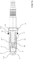
- the single figure shows an embodiment of a spark plug according to the invention. This is a prechamber spark plug, it being expressly pointed out that the device according to the invention can be designed as any type of spark plug.
- the spark plug comprises a cap 2 which serves as a ground electrode 1 and which is made of nickel or a nickel alloy, for example.
- An ignition electrode 4 is arranged within the antechamber 3 formed by the cap 2.
- the cap 2 is connected to the housing 6 via a weld 5.
- the housing 6 is formed by a front housing part 7 and a rear housing part 8.
- the front housing part 7 directly adjoins the ground electrode 1 and serves as a dissipation area 9, namely to dissipate the combustion heat introduced into the spark plug.
- the discharge area 9, i.e. the front housing part 7, is made of a material with a high thermal conductivity of more than 150 W / mK or more than 200 W / mK.
- the discharge area can be made of copper or a copper-based alloy with small proportions of nickel and / or beryllium.
- a thread 10 is formed on the front housing part 7, by means of which the spark plug can be screwed into the cylinder.
- the front housing part 7 are at least partially conical in order to achieve a clamping with the cylinder.
- the ignition electrode 4 is implemented in the form of two strips, each with ends curved in an arc.
- the strips each have two ends that act as ignition surfaces. It is conceivable that the strips consist of an iridium alloy or a platinum alloy.
- a supply line (not shown) which runs within the insulator 11.
- the insulator 11 consists for example of a ceramic, in particular aluminum oxide (coefficient of thermal expansion ⁇ of approx. 8.5 ⁇ 10 -6 1 / K) or aluminum nitride.
- the single figure also shows that the front housing part 7 is connected to the rear housing part 8 via a weld 12.
- the rear housing part 8 engages behind a projection 13 of the insulator 11, so that the insulator 11 is held within the housing 6 with prestress.
- the rear housing part 8 is made of a material which - at least in the temperature range relevant for a spark plug - has a lower coefficient of thermal expansion than the material of the insulator 11.
- a nickel-iron alloy Ni Co 29/18 with a coefficient of thermal expansion ⁇ of 5 • 10 -6 1 / K to 8 • 10 -6 1 / K).
- a sealing ring 14 is arranged, which is made of copper, for example.
- the rear housing part 8 has an engagement point 15, for example a hexagon, for a handling means, so that the spark plug can be screwed into the ignition chamber with a corresponding tool.
Landscapes
- Spark Plugs (AREA)
Description
- Die vorliegende Erfindung betrifft eine Zündkerze, insbesondere Vorkammerzündkerze, mit einem Gehäuse, einer Zündelektrode und einer Masseelektrode, wobei die Zündelektrode über eine Versorgungsleitung mit einer elektrischen Spannung beaufschlagbar ist und wobei die Versorgungsleitung zumindest teilweise innerhalb eines Isolators verläuft.
- Zündkerzen der in Rede stehenden Art sind seit Jahren aus der Praxis bekannt. Diese dienen bei einem Verbrennungsmotor der Entflammung des verdichteten Kraftstoff-Luft-Gemisches im Brennraum des Zylinders. Dabei zündet ein Hochspannungsfunken an der Zündkerze das verdichtete Kraftstoff-Luft-Gemisch.
- Beispielsweise ist aus der
WO 2008/031482 A1 eine Zündkerze umfassend eine Zündelektrode und eine Masseelektrode beschrieben. Die Zündkerze weißt ein aus einem Gehäusekopf und einer Halterung ausgebildetes Gehäuse auf, das einen Teil eines Isolators in sich aufnimmt. Der Isolator umschließt eine Versorgungsleitung, welche zur Beaufschlagung der Zündelektrode mit elektrischer Spannung dient. Der Gehäusekopf ist aus Stahl hergestellt und mit der aus einer Nickel-Eisen-Legierung bestehenden Halterung über eine Schweißnaht verbunden. Die Nickel-Eisen-Legierung weißt einen Wärmeausdehnungskoeffizienten auf, der geringer ist als der Wärmeausdehnungskoeffizient des Isolators, so dass die Vorspannung, mit welcher der Isolator in dem Gehäuse angeordnet ist, mit steigender Temperatur ebenfalls ansteigt. - Bei der bekannten Zündkerze ist problematisch, dass sich diese im Betrieb zu stark aufheizt, was sich negativ auf die für die Lebensdauer der Zündkerze relevanten Bereiche, wie zum Beispiel die Elektroden und einen ggf. vorhandenen Entstörwiderstand auswirkt. Im Extremfall kann es zu Glühzündungen oder klopfenden Verbrennungen im Bereich der Zündkerze kommen, so dass die Funktion des Motors stark beeinträchtigt ist.
- Der vorliegenden Erfindung liegt daher die Aufgabe zugrunde, eine Zündkerze der eingangs genannten Art derart auszugestalten und weiterzubilden, dass mit konstruktiv einfachen Mitteln eine Überhitzung der Zündkerze vermieden wird.
- Erfindungsgemäß wird die voranstehende Aufgabe durch die Merkmale des Anspruchs 1 gelöst. Danach ist die in Rede stehende Zündkerze dadurch gekennzeichnet, dass zumindest ein Ableitungsbereich des Gehäuses aus einem Material mit einer Wärmeleitfähigkeit von über 150 W/mK hergestellt ist.
- In erfindungsgemäßer Weise ist erkannt worden, dass die zugrundeliegende Aufgabe durch die Anordnung eines Ableitungsbereichs an dem Gehäuse in verblüffend einfacher Weise gelöst werden kann. Der Ableitungsbereich dient dabei zur Ableitung der in die Zündkerze eingetragenen Verbrennungswärme an die Umgebung. Der Ableitungsbereich ist aus einem Material mit einer Wärmeleitfähigkeit von über 150 W/mK hergestellt, so dass eine ausreichend hohe Wärmeableitung gewährleistet ist und kann sich in vorteilhafter Weise unmittelbar an die Masseelektrode anschließen. Durch diese einfache konstruktive Maßnahme wird eine Überhitzung der Zündkerze, insbesondere der für die Lebensdauer der Zündkerze relevanten Bereiche, zuverlässig verhindert. Dadurch kann das Auftreten von Glühzündungen oder klopfenden Verbrennungen im Bereich der Zündkerze erheblich reduziert werden. Wesentlich für die erfindungsgemäße Vorrichtung ist, dass der Ableitungsbereich eine Wärmeleitfähigkeit aufweist, die über der Wärmeleitfähigkeit von Stahl liegt, was das aus dem Stand der Technik bekannte Material zur Fertigung des Gehäuses ist. Entgegen eines Vorurteils der Fachwelt hat sich gezeigt, dass sich Materialien mit einer höheren Wärmeleitfähigkeit trotz des damit meist einhergehenden höheren Wärmeausdehnungskoeffizienten zur Fertigung zumindest eines Bereichs des Gehäuses einer Zündkerze eignen.
- An dieser Stelle sei darauf hingewiesen, dass sich die angegebene Wärmeleitfähigkeit insbesondere auf den für eine Zündkerze relevanten Temperaturbereich bezieht. Die Angabe der Wärmeleitfähigkeit erfolgt in den Einheiten Watt pro Meter und Kelvin.
- In vorteilhafter Weise kann der Ableitungsbereich eine Wärmeleitfähigkeit von über 200 W/mK aufweisen. Bei einer solch hohen Wärmeleitfähigkeit ist eine Überhitzung der Zündkerze nahezu ausgeschlossen, so dass die durch die Überhitzung bedingten Probleme effektiv vermieden werden.
- Zur Realisierung eines Ableitungsbereiches mit einer entsprechend hohen Wärmeleitfähigkeit kann der Ableitungsbereich aus Kupfer, einer Kupferlegierung oder einer Kupferbasislegierung umfassend Anteile von Nickel und/oder Beryllium hergestellt sein.
- In vorteilhafter Weise kann das Gehäuse einteilig ausgebildet sein. Dadurch wird eine besonders einfache Konstruktion der Zündkerze realisiert, so dass diese kostengünstig in der Herstellung ist. Dabei kann das gesamte Gehäuse als Ableitungsbereich ausgebildet sein.
- Alternativ ist denkbar, dass das Gehäuse einen vorderen Gehäuseteil und einen hinteren Gehäuseteil aufweist, somit zweiteilig aufgebaut ist. In vorteilhafter Weise kann der vordere Gehäuseteil mit dem hinteren Gehäuseteil über eine Schweißnaht verbunden ist. Die Schweißnaht kann beispielsweise über Wolfram-Inertgas-Schweißen (WIG), Plasmaschweißen, Elektronenschweißen oder Laserschweißen hergestellt sein.
- In weiter vorteilhafter Weise kann der Ableitungsbereich durch den vorderen Gehäuseteil realisiert sein, dieser somit insgesamt aus einem Material mit einer Wärmeleitfähigkeit von über 150 W/mK hergestellt sein. Dadurch ist die Ableitung der Prozesswärme nochmals verbessert und die Konstruktion der Zündkerze vereinfacht. Ein weiterer Vorteil einer solchen Ausgestaltung besteht darin, dass sich der vordere Gehäuseteil aufgrund seiner hohen Wärmeleitfähigkeit für eines der voranstehenden Schweißverfahren besonders eignet. Alternativ oder zusätzlich kann der Ableitungsbereich durch den hinteren Gehäuseteil gebildet sein.
- Um eine ausreichend stabile Konstruktion zu gewährleisten kann der hintere Gehäuseteil einen Wärmeausdehnungskoeffizienten aufweisen, der kleiner oder gleich dem Wärmeausdehnungskoeffizienten des Isolators ist. Im Konkreten kann der hintere Gehäuseteil aus einer Nickel-Eisen-Legierung bestehen, beispielsweise Ni Co 29/18 mit einem Wärmeausdehnungskoeffizient α von 5•10-6 1/K bis 8•10-6 1/K), wobei der Isolator aus einer Keramik, insbesondere Aluminiumoxid (Wärmeausdehnungskoeffizient α von ca. 8,5•10-6 1/K) oder Aluminiumnitrid hergestellt sein kann.
- In vorteilhafter Weise kann die Außenseite des Gehäuses zumindest bereichsweise konisch ausgebildet sein und/oder ein Gewinde aufweisen. Dabei kann es sich in besonders vorteilhafter Weise um einen entsprechend ausgebildeten vorderen Gehäuseteil handeln. Dadurch ist eine sichere Verbindung und Abdichtung zwischen Zündkerze und Zylinder gewährleistet.
- Eine besonders sichere Verbindung zwischen Gehäuse und Isolator kann realisiert sein, indem das Gehäuse den Isolator hintergreift und unter Vorspannung in dem Gehäuse hält, vorzugsweise an einen Dichtring, insbesondere aus Kupfer, presst. In besonders vorteilhafter Weise kann der hintere Gehäuseteil den Isolator hintergreifen und unter Vorspannung in dem Gehäuse halten.
- Ein besondere kombinatorischer Effekt ist erzielbar, indem der vordere Gehäuseteil insgesamt als Ableitungsbereich ausgebildet ist und mit dem hinteren Gehäuseteil über eine Schweißnaht verbunden ist, wobei der hintere Gehäuseteil einen Wärmeausdehnungskoeffizienten aufweist, der kleiner oder gleich dem Wärmeausdehnungskoeffizienten des Isolationskörpers ist. Bei einer solchen Ausgestaltung ist die Ableitung der Wärme von der Zündkerze durch den vorderen Gehäuseteil ermöglicht, wobei der hintere Gehäuseteil aufgrund seines geringen Wärmeausdehnungskoeffizienten den Isolator mit einer höheren Vorspannung in dem Gehäuse hält, je höher die Temperatur ansteigt. Dadurch wird ein höherer Wärmeausdehnungskoeffizient des vorderen Gehäuseteils, welches eine hohe Wärmeleitfähigkeit aufweist, kompensiert und der Zylinder zuverlässig durch die Zündkerze verschlossen.
- Es gibt nun verschiedene Möglichkeiten, die Lehre der vorliegenden Erfindung in vorteilhafter Weise auszugestalten und weiterzubilden. Dazu ist einerseits auf die dem Anspruch 1 nachgeordneten Ansprüche und andererseits auf die nachfolgende Erläuterung bevorzugter Ausführungsbeispiele der Erfindung anhand der Zeichnung zu verweisen. In Verbindung mit der Erläuterung der bevorzugten Ausführungsbeispiele der Erfindung anhand der Zeichnung werden auch im Allgemeinen bevorzugte Ausgestaltungen und Weiterbildungen der Lehre erläutert. In der Zeichnung zeigt die
- einzige Fig.
- in einer schematischen, geschnittenen Darstellung ein Ausführungsbeispiel einer erfindungsgemäßen Zündkerze.
- Die einzige Figur zeigt ein Ausführungsbeispiel einer erfindungsgemäßen Zündkerze. Dabei handelt es sich um eine Vorkammerzündkerze, wobei ausdrücklich darauf hingewiesen wird, dass die erfindungsgemäße Vorrichtung als eine beliebige Zündkerzenart ausgebildet sein kann.
- Die Zündkerze umfasst eine als Masseelektrode 1 dienende Kappe 2, die beispielsweise aus Nickel oder einer Nickellegierung besteht. Innerhalb des von der Kappe 2 gebildeten Vorraums 3 ist eine Zündelektrode 4 angeordnet. Die Kappe 2 ist über eine Schweißnaht 5 mit dem Gehäuse 6 verbunden. In dem hier dargestellten Ausführungsbeispiel ist das Gehäuse 6 durch einen vorderen Gehäuseteil 7 und einen hinteren Gehäuseteil 8 gebildet.
- Der vordere Gehäuseteil 7 schließt sich unmittelbar an die Masseelektrode 1 an und dient als Ableitungsbereich 9, um nämlich die in die Zündkerze eingetragene Verbrennungswärme abzuleiten. Dazu ist der Ableitungsbereich 9, d.h. der vordere Gehäuseteil 7, aus einem Material mit einer hohen Wärmeleitfähigkeit von über 150 W/mK bzw. von über 200 W/mK hergestellt. Im Konkreten kann der Ableitungsbereich aus Kupfer bzw. einer Kupferbasislegierung mit geringen Anteilen von Nickel und/oder Beryllium hergestellt sein.
- An dem vorderen Gehäuseteil 7 ist ein Gewinde 10 ausgebildet, über das die Zündkerze in den Zylinder einschraubbar ist. Alternativ oder zusätzlich kann der vordere Gehäuseteil 7 zumindest bereichsweise konisch verlaufen, um eine Klemmung mit dem Zylinder zu erreichen.
- Die Zündelektrode 4 ist in dem hier dargestellten Ausführungsbeispiel in Form von zwei Streifen mit jeweils bogenförmig gekrümmten Enden realisiert. Die Streifen weisen jeweils zwei Enden auf, die als Zündflächen wirken. Dabei ist denkbar, dass die Streifen aus einer Iridiumlegierung oder einer Platinlegierung bestehen.
- Um die Zündelektrode 4 mit elektrischer Spannung zu versorgen, ist eine nicht dargestellte Versorgungsleitung vorgesehen, die innerhalb des Isolators 11 verläuft. Der Isolator 11 besteht beispielsweise aus einer Keramik, insbesondere Aluminiumoxid (Wärmeausdehnungskoeffizient α von ca. 8,5•10-6 1/K) oder Aluminiumnitrid.
- In der einzigen Figur ist des Weiteren gezeigt, dass der vordere Gehäuseteil 7 mit dem hinteren Gehäuseteil 8 über eine Schweißnaht 12 verbunden ist. Der hintere Gehäuseteil 8 hintergreift einen Vorsprung 13 des Isolators 11, so dass der Isolator 11 mit Vorspannung innerhalb des Gehäuses 6 gehalten ist. In dem dargestellten Ausführungsbeispiel ist der hintere Gehäuseteil 8 aus einem Material hergestellt, das - zumindest in dem für eine Zündkerze relevanten Temperaturbereich - einen geringeren Wärmeausdehnungskoeffizienten aufweist, als das Material des Isolators 11. Hierbei kann es sich insbesondere eine Nickel-Eisen-Legierung (Ni Co 29/18 mit Wärmeausdehnungskoeffizient α von 5•10-6 1/K bis 8•10-6 1/K) handeln. Bei der im Betrieb erfolgenden Erwärmung der Zündkerze erhöht sich somit die Vorspannung, unter welcher der Isolator 11 in dem Gehäuse 6 gehalten ist, so dass eine zuverlässige Abdichtung der Zündkerze gegenüber dem Brennraum erzielt wird. Zur Abdichtung zwischen Isolator 11 und vorderem Gehäuseteil 7 ist ein Dichtring 14 angeordnet, der beispielsweise aus Kupfer besteht.
- Des Weiteren weist der hintere Gehäuseteil 8 eine Angriffstelle 15, beispielsweise ein Sechskant, für ein Handhabungsmittel auf, so dass die Zündkerze mit einem korrespondierenden Werkzeug in den Zündraum einschraubbar ist.
- Hinsichtlich weiterer vorteilhafter Ausgestaltungen der erfindungsgemäßen Vorrichtung wird zur Vermeidung von Wiederholungen auf den allgemeinen Teil der Beschreibung sowie auf die beigefügten Ansprüche verwiesen.
- Schließlich sei ausdrücklich darauf hingewiesen, dass die voranstehend beschriebenen Ausführungsbeispiele der erfindungsgemäßen Vorrichtung lediglich zur Erörterung der beanspruchten Lehre dienen, diese jedoch nicht auf die Ausführungsbeispiele einschränken.
-
- 1
- Masseelektrode
- 2
- Kappe
- 3
- Vorkammer
- 4
- Zündelektrode
- 5
- Schweißnaht
- 6
- Gehäuse
- 7
- vorderer Gehäuseteil
- 8
- hinterer Gehäuseteil
- 9
- Ableitungsbereich
- 10
- Gewinde
- 11
- Isolator
- 12
- Schweißnaht
- 13
- Vorsprung
- 14
- Dichtring
- 15
- Angriffstelle
Claims (7)
- Zündkerze, insbesondere Vorkammerzündkerze, mit einem Gehäuse (6), einer Zündelektrode (4) und einer Masseelektrode (1), wobei die Zündelektrode (4) über eine Versorgungsleitung mit einer elektrischen Spannung beaufschlagbar ist, wobei die Versorgungsleitung zumindest teilweise innerhalb eines Isolators (11) verläuft, wobei das Gehäuse (6) einen vorderen Gehäuseteil (7) und einen hinteren Gehäuseteil (8) aufweist und wobei das hintere Gehäuseteil (8) den Isolator (11) hintergreift, so dass der Isolator (11) unter Vorspannung zwischen dem vorderen Gehäuseteil (7) und der hinteren Gehäuseteil (8) angeordnet ist,
dadurch gekennzeichnet, dass der vordere Gehäuseteil (7) insgesamt aus einem Material mit einer Wärmeleitfähigkeit von über 150 W/mK hergestellt ist und somit als Ableitungsbereich (9) dient. - Zündkerze nach Anspruch 1, dadurch gekennzeichnet, dass sich der Ableitungsbereich (9) unmittelbar an die Masseelektrode (1) anschließt und/oder dass der Ableitungsbereich (9) eine Wärmeleitfähigkeit von über 200 W/mK aufweist.
- Zündkerze nach Anspruch 1 oder 2, dadurch gekennzeichnet, dass der Ableitungsbereich (9) aus Kupfer oder aus einer Kupferlegierung oder aus einer Kupferbasislegierung umfassend Anteile von Nickel und/oder Beryllium hergestellt ist.
- Zündkerze nach einem der Ansprüche 1 bis 3, dadurch gekennzeichnet, dass der vordere Gehäuseteil (7) mit dem hinteren Gehäuseteil (8) über eine Schweißnaht (12) verbunden ist.
- Zündkerze nach einem der Ansprüche 1 bis 4, dadurch gekennzeichnet, dass der hintere Gehäuseteil (8) einen Wärmeausdehnungskoeffizienten aufweist, der kleiner oder gleich dem Wärmeausdehnungskoeffizienten des Isolators (11) ist.
- Zündkerze nach einem der Ansprüche 1 bis 5, dadurch gekennzeichnet, dass der hintere Gehäuseteil (8) aus einer Nickel-Eisen-Legierung besteht.
- Vorrichtung nach einem der Ansprüche 1 bis 6, dadurch gekennzeichnet, dass das Gehäuse (6), insbesondere der vordere Gehäuseteil (7), an seiner Außenseite zumindest bereichsweise konisch ausgebildet ist und/oder ein Gewinde (10) aufweist.
Applications Claiming Priority (2)
| Application Number | Priority Date | Filing Date | Title |
|---|---|---|---|
| DE102016206992.6A DE102016206992A1 (de) | 2016-04-25 | 2016-04-25 | Zündkerze |
| PCT/DE2017/200004 WO2017186238A1 (de) | 2016-04-25 | 2017-01-23 | Zündkerze |
Publications (3)
| Publication Number | Publication Date |
|---|---|
| EP3281263A1 EP3281263A1 (de) | 2018-02-14 |
| EP3281263B1 true EP3281263B1 (de) | 2021-03-24 |
| EP3281263B8 EP3281263B8 (de) | 2021-04-28 |
Family
ID=58410060
Family Applications (1)
| Application Number | Title | Priority Date | Filing Date |
|---|---|---|---|
| EP17713153.9A Active EP3281263B8 (de) | 2016-04-25 | 2017-01-23 | Zündkerze |
Country Status (3)
| Country | Link |
|---|---|
| EP (1) | EP3281263B8 (de) |
| DE (1) | DE102016206992A1 (de) |
| WO (1) | WO2017186238A1 (de) |
Families Citing this family (30)
| Publication number | Priority date | Publication date | Assignee | Title |
|---|---|---|---|---|
| DE102018206784A1 (de) * | 2018-05-03 | 2019-11-07 | Robert Bosch Gmbh | Vorkammer-Zündkerze |
| JP7159810B2 (ja) * | 2018-11-22 | 2022-10-25 | トヨタ自動車株式会社 | 副室付内燃機関 |
| JP7227842B2 (ja) * | 2019-05-07 | 2023-02-22 | 日本特殊陶業株式会社 | スパークプラグ |
| DE102019116191A1 (de) * | 2019-06-14 | 2020-12-17 | Bayerische Motoren Werke Aktiengesellschaft | Vorkammerzündsystem für eine fremd gezündete Hubkolben-Brennkraftmaschine |
| DE102019122527A1 (de) * | 2019-08-21 | 2021-02-25 | Bayerische Motoren Werke Aktiengesellschaft | Vorkammerzündsystem für eine fremd gezündete Hubkolben-Brennkraftmaschine |
| DE102019122529A1 (de) * | 2019-08-21 | 2021-02-25 | Bayerische Motoren Werke Aktiengesellschaft | Vorkammerzündsystem für eine fremd gezündete Hubkolben-Brennkraftmaschine |
| DE102019122530A1 (de) * | 2019-08-21 | 2021-02-25 | Bayerische Motoren Werke Aktiengesellschaft | Vorkammerzündsystem für eine fremd gezündete Hubkolben-Brennkraftmaschine |
| DE102019122531A1 (de) * | 2019-08-21 | 2021-02-25 | Bayerische Motoren Werke Aktiengesellschaft | Fremd gezündete Hubkolben-Brennkraftmaschine mit einem Vorkammerzündsystem |
| DE102019122532A1 (de) * | 2019-08-21 | 2021-02-25 | Bayerische Motoren Werke Aktiengesellschaft | Vorkammerzündsystem für eine fremd gezündete Hubkolben-Brennkraftmaschine |
| DE102019122526A1 (de) * | 2019-08-21 | 2021-02-25 | Bayerische Motoren Werke Aktiengesellschaft | Vorkammerzündsystem für eine fremd gezündete Hubkolben-Brennkraftmaschine |
| DE102019122559A1 (de) * | 2019-08-22 | 2021-02-25 | Bayerische Motoren Werke Aktiengesellschaft | Fremd gezündete Hubkolben-Brennkraftmaschine mit einem Vorkammerzündsystem |
| DE102019126963A1 (de) * | 2019-10-08 | 2021-04-08 | Bayerische Motoren Werke Aktiengesellschaft | Vorkammerzündsystem für eine fremd gezündete Hubkolben-Brennkraftmaschine |
| DE102019126964A1 (de) * | 2019-10-08 | 2021-04-08 | Bayerische Motoren Werke Aktiengesellschaft | Verfahren zum Betreiben einer fremd gezündeten Viertakt-Hubkolben-Brennkraftmaschine mit einem Vorkammerzündsystem |
| DE102019131360B4 (de) | 2019-11-20 | 2024-05-02 | Bayerische Motoren Werke Aktiengesellschaft | Zylinderkopf für eine fremd gezündete Hubkolben-Brennkraftmaschine |
| DE102020101552A1 (de) | 2020-01-23 | 2021-07-29 | Bayerische Motoren Werke Aktiengesellschaft | Verfahren zum Betreiben einer fremd gezündeten Hubkolben-Brennkraftmaschine |
| DE102020103863B4 (de) * | 2020-02-14 | 2023-04-27 | Bayerische Motoren Werke Aktiengesellschaft | Fremd gezündete Hubkolben-Brennkraftmaschine mit einem Vorkammerzündsystem |
| DE102020105924A1 (de) | 2020-03-05 | 2021-09-09 | Bayerische Motoren Werke Aktiengesellschaft | Fremd gezündete Hubkolben-Brennkraftmaschine mit einem Vorkammerzündsystem |
| DE102020105921A1 (de) | 2020-03-05 | 2021-09-09 | Bayerische Motoren Werke Aktiengesellschaft | Fremd gezündete Hubkolben-Brennkraftmaschine mit einem Vorkammerzündsystem |
| DE102020106397B4 (de) | 2020-03-10 | 2024-08-29 | Bayerische Motoren Werke Aktiengesellschaft | Fremd gezündete Hubkolben-Brennkraftmaschine mit einem Vorkammerzündsystem |
| DE102020106398A1 (de) | 2020-03-10 | 2021-09-16 | Bayerische Motoren Werke Aktiengesellschaft | Fremd gezündete Hubkolben-Brennkraftmaschine mit einem Vorkammerzündsystem |
| DE102020107368A1 (de) | 2020-03-18 | 2021-09-23 | Bayerische Motoren Werke Aktiengesellschaft | Fremd gezündete Hubkolben-Brennkraftmaschine mit einem Vorkammerzündsystem |
| DE102020107370A1 (de) | 2020-03-18 | 2021-09-23 | Bayerische Motoren Werke Aktiengesellschaft | Fremd gezündete Hubkolben-Brennkraftmaschine mit einem Vorkammerzündsystem |
| DE102020107841A1 (de) | 2020-03-23 | 2021-09-23 | Bayerische Motoren Werke Aktiengesellschaft | Fremd gezündete Hubkolben-Brennkraftmaschine mit einem Vorkammerzündsystem |
| DE102020108564A1 (de) | 2020-03-27 | 2021-09-30 | Bayerische Motoren Werke Aktiengesellschaft | Fremd gezündete Hubkolben-Brennkraftmaschine mit einem Vorkammerzündsystem |
| DE102020109161A1 (de) | 2020-04-02 | 2021-10-07 | Bayerische Motoren Werke Aktiengesellschaft | Verfahren zum Betreiben einer fremd gezündeten Viertakt-Hubkolben-Brennkraftmaschine mit einem Vorkammerzündsystem |
| DE102020110395B4 (de) | 2020-04-16 | 2026-04-16 | Bayerische Motoren Werke Aktiengesellschaft | Fremd gezündete Hubkolben-Brennkraftmaschine mit einem Vorkammerzündsystem |
| DE102020215946A1 (de) | 2020-12-15 | 2022-06-15 | Robert Bosch Gesellschaft mit beschränkter Haftung | Wärmeoptimierte Vorkammerzündkerze |
| DE102023105825B3 (de) | 2023-03-09 | 2024-08-01 | Bayerische Motoren Werke Aktiengesellschaft | Vorkammerzündeinrichtung für eine Verbrennungskraftmaschine, insbesondere eines Kraftfahrzeugs, sowie Verbrennungskraftmaschine, insbesondere für ein Kraftfahrzeug |
| DE102023004631B4 (de) * | 2023-11-15 | 2026-03-05 | Mercedes-Benz Group AG | Vorkammerzündeinrichtung für eine Verbrennungskraftmaschine sowie Verbrennungskraftmaschine für ein Kraftfahrzeug |
| DE102023004632A1 (de) * | 2023-11-15 | 2025-05-15 | Mercedes-Benz Group AG | Vorkammerzündeinrichtung für eine Verbrennungskraftmaschine sowie Verbrennungskraftmaschine |
Citations (1)
| Publication number | Priority date | Publication date | Assignee | Title |
|---|---|---|---|---|
| DE68924526T2 (de) * | 1989-01-09 | 1996-04-04 | Ngk Spark Plug Co | Zündkerzenzusammenbau. |
Family Cites Families (5)
| Publication number | Priority date | Publication date | Assignee | Title |
|---|---|---|---|---|
| DE2012516A1 (de) * | 1970-03-17 | 1971-09-30 | Daimler Benz Ag | Zündkerze, insbesondere fur Rotations kolben Brennkraftmaschinen |
| FR2846042B1 (fr) * | 2002-10-18 | 2005-02-04 | Peugeot Citroen Automobiles Sa | Dispositif d'allumage a prechambre realisee dans un materiau a conductivite thermique elevee, pour un moteur a combustion interne, et allumeur a prechambre |
| DE102006043593B3 (de) | 2006-09-16 | 2008-04-10 | Multitorch Gmbh | Zündkerze |
| US8912716B2 (en) * | 2011-03-21 | 2014-12-16 | Denso International America, Inc. | Copper core combustion cup for pre-chamber spark plug |
| JP2014007071A (ja) * | 2012-06-25 | 2014-01-16 | Nippon Soken Inc | 点火プラグ |
-
2016
- 2016-04-25 DE DE102016206992.6A patent/DE102016206992A1/de not_active Ceased
-
2017
- 2017-01-23 WO PCT/DE2017/200004 patent/WO2017186238A1/de not_active Ceased
- 2017-01-23 EP EP17713153.9A patent/EP3281263B8/de active Active
Patent Citations (1)
| Publication number | Priority date | Publication date | Assignee | Title |
|---|---|---|---|---|
| DE68924526T2 (de) * | 1989-01-09 | 1996-04-04 | Ngk Spark Plug Co | Zündkerzenzusammenbau. |
Also Published As
| Publication number | Publication date |
|---|---|
| DE102016206992A1 (de) | 2017-10-26 |
| WO2017186238A1 (de) | 2017-11-02 |
| EP3281263B8 (de) | 2021-04-28 |
| EP3281263A1 (de) | 2018-02-14 |
Similar Documents
| Publication | Publication Date | Title |
|---|---|---|
| WO2017186238A1 (de) | Zündkerze | |
| DE102015204814B3 (de) | Vorkammerzündkerze zur Zündung eines Kraftstoff-Luft-Gemisches in einem Verbrennungsmotor | |
| DE102015114453B4 (de) | Zündkerze für eine Brennkraftmaschine und Verfahren zur Herstellung einer Zündkerze | |
| AT516835B1 (de) | Zündkerze | |
| EP3406009B1 (de) | Zündkerze und ein verfahren zur herstellung einer zündkerze | |
| EP3255744B1 (de) | Vorkammerzündkerze | |
| EP4136332B1 (de) | Fremd gezündete hubkolben-brennkraftmaschine mit einem vorkammerzündsystem | |
| DE112020007183T5 (de) | Zündkerze | |
| DE102007050634A1 (de) | Zündkerze | |
| EP3281264B1 (de) | Zündkerze | |
| DE10340043A1 (de) | Zündkerze | |
| DE102020106397B4 (de) | Fremd gezündete Hubkolben-Brennkraftmaschine mit einem Vorkammerzündsystem | |
| DE102015102745B4 (de) | Zündkerze für einen Vorkammer-Verbrennungsmotor | |
| EP3420615B1 (de) | Vorkammerzündkerze | |
| DE102020103863B4 (de) | Fremd gezündete Hubkolben-Brennkraftmaschine mit einem Vorkammerzündsystem | |
| DE102014105687B3 (de) | Zündkerze | |
| DE102019122532A1 (de) | Vorkammerzündsystem für eine fremd gezündete Hubkolben-Brennkraftmaschine | |
| DE10156949B4 (de) | Zündkerze | |
| DE10340042B4 (de) | Zündkerze | |
| DE112017007557B4 (de) | Zündkerze | |
| DE3726714C2 (de) | ||
| EP4068536A1 (de) | Vorkammerzündkerze und ein verfahren zur herstellung einer vorkammerzündkerze | |
| DE102005046431A1 (de) | Zündkerze mit einem einen Isolator umgebenden Gehäuse | |
| DE102019123178A1 (de) | Vorkammerzündsystem für eine fremd gezündete Hubkolben-Brennkraftmaschine |
Legal Events
| Date | Code | Title | Description |
|---|---|---|---|
| STAA | Information on the status of an ep patent application or granted ep patent |
Free format text: STATUS: UNKNOWN |
|
| STAA | Information on the status of an ep patent application or granted ep patent |
Free format text: STATUS: THE INTERNATIONAL PUBLICATION HAS BEEN MADE |
|
| PUAI | Public reference made under article 153(3) epc to a published international application that has entered the european phase |
Free format text: ORIGINAL CODE: 0009012 |
|
| STAA | Information on the status of an ep patent application or granted ep patent |
Free format text: STATUS: REQUEST FOR EXAMINATION WAS MADE |
|
| 17P | Request for examination filed |
Effective date: 20171108 |
|
| AK | Designated contracting states |
Kind code of ref document: A1 Designated state(s): AL AT BE BG CH CY CZ DE DK EE ES FI FR GB GR HR HU IE IS IT LI LT LU LV MC MK MT NL NO PL PT RO RS SE SI SK SM TR |
|
| AX | Request for extension of the european patent |
Extension state: BA ME |
|
| DAV | Request for validation of the european patent (deleted) | ||
| DAX | Request for extension of the european patent (deleted) | ||
| STAA | Information on the status of an ep patent application or granted ep patent |
Free format text: STATUS: EXAMINATION IS IN PROGRESS |
|
| 17Q | First examination report despatched |
Effective date: 20200228 |
|
| GRAP | Despatch of communication of intention to grant a patent |
Free format text: ORIGINAL CODE: EPIDOSNIGR1 |
|
| STAA | Information on the status of an ep patent application or granted ep patent |
Free format text: STATUS: GRANT OF PATENT IS INTENDED |
|
| INTG | Intention to grant announced |
Effective date: 20201021 |
|
| GRAS | Grant fee paid |
Free format text: ORIGINAL CODE: EPIDOSNIGR3 |
|
| GRAA | (expected) grant |
Free format text: ORIGINAL CODE: 0009210 |
|
| STAA | Information on the status of an ep patent application or granted ep patent |
Free format text: STATUS: THE PATENT HAS BEEN GRANTED |
|
| AK | Designated contracting states |
Kind code of ref document: B1 Designated state(s): AL AT BE BG CH CY CZ DE DK EE ES FI FR GB GR HR HU IE IS IT LI LT LU LV MC MK MT NL NO PL PT RO RS SE SI SK SM TR |
|
| REG | Reference to a national code |
Ref country code: GB Ref legal event code: FG4D Free format text: NOT ENGLISH |
|
| REG | Reference to a national code |
Ref country code: CH Ref legal event code: PK Free format text: BERICHTIGUNG B8 Ref country code: CH Ref legal event code: EP |
|
| REG | Reference to a national code |
Ref country code: DE Ref legal event code: R096 Ref document number: 502017009803 Country of ref document: DE |
|
| REG | Reference to a national code |
Ref country code: IE Ref legal event code: FG4D Free format text: LANGUAGE OF EP DOCUMENT: GERMAN |
|
| REG | Reference to a national code |
Ref country code: AT Ref legal event code: REF Ref document number: 1375464 Country of ref document: AT Kind code of ref document: T Effective date: 20210415 |
|
| RAP4 | Party data changed (patent owner data changed or rights of a patent transferred) |
Owner name: DKT VERWALTUNGS-GMBH |
|
| REG | Reference to a national code |
Ref country code: LT Ref legal event code: MG9D |
|
| PG25 | Lapsed in a contracting state [announced via postgrant information from national office to epo] |
Ref country code: NO Free format text: LAPSE BECAUSE OF FAILURE TO SUBMIT A TRANSLATION OF THE DESCRIPTION OR TO PAY THE FEE WITHIN THE PRESCRIBED TIME-LIMIT Effective date: 20210624 Ref country code: HR Free format text: LAPSE BECAUSE OF FAILURE TO SUBMIT A TRANSLATION OF THE DESCRIPTION OR TO PAY THE FEE WITHIN THE PRESCRIBED TIME-LIMIT Effective date: 20210324 Ref country code: FI Free format text: LAPSE BECAUSE OF FAILURE TO SUBMIT A TRANSLATION OF THE DESCRIPTION OR TO PAY THE FEE WITHIN THE PRESCRIBED TIME-LIMIT Effective date: 20210324 Ref country code: GR Free format text: LAPSE BECAUSE OF FAILURE TO SUBMIT A TRANSLATION OF THE DESCRIPTION OR TO PAY THE FEE WITHIN THE PRESCRIBED TIME-LIMIT Effective date: 20210625 Ref country code: BG Free format text: LAPSE BECAUSE OF FAILURE TO SUBMIT A TRANSLATION OF THE DESCRIPTION OR TO PAY THE FEE WITHIN THE PRESCRIBED TIME-LIMIT Effective date: 20210624 |
|
| PG25 | Lapsed in a contracting state [announced via postgrant information from national office to epo] |
Ref country code: RS Free format text: LAPSE BECAUSE OF FAILURE TO SUBMIT A TRANSLATION OF THE DESCRIPTION OR TO PAY THE FEE WITHIN THE PRESCRIBED TIME-LIMIT Effective date: 20210324 Ref country code: LV Free format text: LAPSE BECAUSE OF FAILURE TO SUBMIT A TRANSLATION OF THE DESCRIPTION OR TO PAY THE FEE WITHIN THE PRESCRIBED TIME-LIMIT Effective date: 20210324 Ref country code: SE Free format text: LAPSE BECAUSE OF FAILURE TO SUBMIT A TRANSLATION OF THE DESCRIPTION OR TO PAY THE FEE WITHIN THE PRESCRIBED TIME-LIMIT Effective date: 20210324 |
|
| REG | Reference to a national code |
Ref country code: NL Ref legal event code: MP Effective date: 20210324 |
|
| PG25 | Lapsed in a contracting state [announced via postgrant information from national office to epo] |
Ref country code: NL Free format text: LAPSE BECAUSE OF FAILURE TO SUBMIT A TRANSLATION OF THE DESCRIPTION OR TO PAY THE FEE WITHIN THE PRESCRIBED TIME-LIMIT Effective date: 20210324 |
|
| PG25 | Lapsed in a contracting state [announced via postgrant information from national office to epo] |
Ref country code: SM Free format text: LAPSE BECAUSE OF FAILURE TO SUBMIT A TRANSLATION OF THE DESCRIPTION OR TO PAY THE FEE WITHIN THE PRESCRIBED TIME-LIMIT Effective date: 20210324 Ref country code: CZ Free format text: LAPSE BECAUSE OF FAILURE TO SUBMIT A TRANSLATION OF THE DESCRIPTION OR TO PAY THE FEE WITHIN THE PRESCRIBED TIME-LIMIT Effective date: 20210324 Ref country code: EE Free format text: LAPSE BECAUSE OF FAILURE TO SUBMIT A TRANSLATION OF THE DESCRIPTION OR TO PAY THE FEE WITHIN THE PRESCRIBED TIME-LIMIT Effective date: 20210324 Ref country code: LT Free format text: LAPSE BECAUSE OF FAILURE TO SUBMIT A TRANSLATION OF THE DESCRIPTION OR TO PAY THE FEE WITHIN THE PRESCRIBED TIME-LIMIT Effective date: 20210324 |
|
| PG25 | Lapsed in a contracting state [announced via postgrant information from national office to epo] |
Ref country code: IS Free format text: LAPSE BECAUSE OF FAILURE TO SUBMIT A TRANSLATION OF THE DESCRIPTION OR TO PAY THE FEE WITHIN THE PRESCRIBED TIME-LIMIT Effective date: 20210724 Ref country code: PT Free format text: LAPSE BECAUSE OF FAILURE TO SUBMIT A TRANSLATION OF THE DESCRIPTION OR TO PAY THE FEE WITHIN THE PRESCRIBED TIME-LIMIT Effective date: 20210726 Ref country code: PL Free format text: LAPSE BECAUSE OF FAILURE TO SUBMIT A TRANSLATION OF THE DESCRIPTION OR TO PAY THE FEE WITHIN THE PRESCRIBED TIME-LIMIT Effective date: 20210324 Ref country code: RO Free format text: LAPSE BECAUSE OF FAILURE TO SUBMIT A TRANSLATION OF THE DESCRIPTION OR TO PAY THE FEE WITHIN THE PRESCRIBED TIME-LIMIT Effective date: 20210324 Ref country code: SK Free format text: LAPSE BECAUSE OF FAILURE TO SUBMIT A TRANSLATION OF THE DESCRIPTION OR TO PAY THE FEE WITHIN THE PRESCRIBED TIME-LIMIT Effective date: 20210324 |
|
| REG | Reference to a national code |
Ref country code: DE Ref legal event code: R097 Ref document number: 502017009803 Country of ref document: DE |
|
| PG25 | Lapsed in a contracting state [announced via postgrant information from national office to epo] |
Ref country code: ES Free format text: LAPSE BECAUSE OF FAILURE TO SUBMIT A TRANSLATION OF THE DESCRIPTION OR TO PAY THE FEE WITHIN THE PRESCRIBED TIME-LIMIT Effective date: 20210324 Ref country code: DK Free format text: LAPSE BECAUSE OF FAILURE TO SUBMIT A TRANSLATION OF THE DESCRIPTION OR TO PAY THE FEE WITHIN THE PRESCRIBED TIME-LIMIT Effective date: 20210324 Ref country code: AL Free format text: LAPSE BECAUSE OF FAILURE TO SUBMIT A TRANSLATION OF THE DESCRIPTION OR TO PAY THE FEE WITHIN THE PRESCRIBED TIME-LIMIT Effective date: 20210324 |
|
| PLBE | No opposition filed within time limit |
Free format text: ORIGINAL CODE: 0009261 |
|
| STAA | Information on the status of an ep patent application or granted ep patent |
Free format text: STATUS: NO OPPOSITION FILED WITHIN TIME LIMIT |
|
| PG25 | Lapsed in a contracting state [announced via postgrant information from national office to epo] |
Ref country code: SI Free format text: LAPSE BECAUSE OF FAILURE TO SUBMIT A TRANSLATION OF THE DESCRIPTION OR TO PAY THE FEE WITHIN THE PRESCRIBED TIME-LIMIT Effective date: 20210324 |
|
| 26N | No opposition filed |
Effective date: 20220104 |
|
| PG25 | Lapsed in a contracting state [announced via postgrant information from national office to epo] |
Ref country code: IS Free format text: LAPSE BECAUSE OF FAILURE TO SUBMIT A TRANSLATION OF THE DESCRIPTION OR TO PAY THE FEE WITHIN THE PRESCRIBED TIME-LIMIT Effective date: 20210724 |
|
| PG25 | Lapsed in a contracting state [announced via postgrant information from national office to epo] |
Ref country code: MC Free format text: LAPSE BECAUSE OF FAILURE TO SUBMIT A TRANSLATION OF THE DESCRIPTION OR TO PAY THE FEE WITHIN THE PRESCRIBED TIME-LIMIT Effective date: 20210324 |
|
| REG | Reference to a national code |
Ref country code: CH Ref legal event code: PL |
|
| GBPC | Gb: european patent ceased through non-payment of renewal fee |
Effective date: 20220123 |
|
| REG | Reference to a national code |
Ref country code: BE Ref legal event code: MM Effective date: 20220131 |
|
| PG25 | Lapsed in a contracting state [announced via postgrant information from national office to epo] |
Ref country code: LU Free format text: LAPSE BECAUSE OF NON-PAYMENT OF DUE FEES Effective date: 20220123 Ref country code: GB Free format text: LAPSE BECAUSE OF NON-PAYMENT OF DUE FEES Effective date: 20220123 |
|
| PG25 | Lapsed in a contracting state [announced via postgrant information from national office to epo] |
Ref country code: BE Free format text: LAPSE BECAUSE OF NON-PAYMENT OF DUE FEES Effective date: 20220131 |
|
| PG25 | Lapsed in a contracting state [announced via postgrant information from national office to epo] |
Ref country code: LI Free format text: LAPSE BECAUSE OF NON-PAYMENT OF DUE FEES Effective date: 20220131 Ref country code: CH Free format text: LAPSE BECAUSE OF NON-PAYMENT OF DUE FEES Effective date: 20220131 |
|
| PG25 | Lapsed in a contracting state [announced via postgrant information from national office to epo] |
Ref country code: IT Free format text: LAPSE BECAUSE OF FAILURE TO SUBMIT A TRANSLATION OF THE DESCRIPTION OR TO PAY THE FEE WITHIN THE PRESCRIBED TIME-LIMIT Effective date: 20210324 Ref country code: IE Free format text: LAPSE BECAUSE OF NON-PAYMENT OF DUE FEES Effective date: 20220123 |
|
| P01 | Opt-out of the competence of the unified patent court (upc) registered |
Effective date: 20230522 |
|
| PG25 | Lapsed in a contracting state [announced via postgrant information from national office to epo] |
Ref country code: HU Free format text: LAPSE BECAUSE OF FAILURE TO SUBMIT A TRANSLATION OF THE DESCRIPTION OR TO PAY THE FEE WITHIN THE PRESCRIBED TIME-LIMIT; INVALID AB INITIO Effective date: 20170123 |
|
| PG25 | Lapsed in a contracting state [announced via postgrant information from national office to epo] |
Ref country code: MK Free format text: LAPSE BECAUSE OF FAILURE TO SUBMIT A TRANSLATION OF THE DESCRIPTION OR TO PAY THE FEE WITHIN THE PRESCRIBED TIME-LIMIT Effective date: 20210324 Ref country code: CY Free format text: LAPSE BECAUSE OF FAILURE TO SUBMIT A TRANSLATION OF THE DESCRIPTION OR TO PAY THE FEE WITHIN THE PRESCRIBED TIME-LIMIT Effective date: 20210324 |
|
| PG25 | Lapsed in a contracting state [announced via postgrant information from national office to epo] |
Ref country code: TR Free format text: LAPSE BECAUSE OF FAILURE TO SUBMIT A TRANSLATION OF THE DESCRIPTION OR TO PAY THE FEE WITHIN THE PRESCRIBED TIME-LIMIT Effective date: 20210324 |
|
| PG25 | Lapsed in a contracting state [announced via postgrant information from national office to epo] |
Ref country code: MT Free format text: LAPSE BECAUSE OF FAILURE TO SUBMIT A TRANSLATION OF THE DESCRIPTION OR TO PAY THE FEE WITHIN THE PRESCRIBED TIME-LIMIT Effective date: 20210324 |
|
| PGFP | Annual fee paid to national office [announced via postgrant information from national office to epo] |
Ref country code: DE Payment date: 20250430 Year of fee payment: 9 |
|
| PGFP | Annual fee paid to national office [announced via postgrant information from national office to epo] |
Ref country code: AT Payment date: 20260119 Year of fee payment: 10 |
|
| PGFP | Annual fee paid to national office [announced via postgrant information from national office to epo] |
Ref country code: FR Payment date: 20260123 Year of fee payment: 10 |