EP3281267B1 - Stromverteilungssystem zum anschluss an ein wechselspannungsnetz - Google Patents
Stromverteilungssystem zum anschluss an ein wechselspannungsnetz Download PDFInfo
- Publication number
- EP3281267B1 EP3281267B1 EP16716836.8A EP16716836A EP3281267B1 EP 3281267 B1 EP3281267 B1 EP 3281267B1 EP 16716836 A EP16716836 A EP 16716836A EP 3281267 B1 EP3281267 B1 EP 3281267B1
- Authority
- EP
- European Patent Office
- Prior art keywords
- power supply
- supply unit
- load
- ups
- current
- Prior art date
- Legal status (The legal status is an assumption and is not a legal conclusion. Google has not performed a legal analysis and makes no representation as to the accuracy of the status listed.)
- Active
Links
Images


Classifications
-
- H—ELECTRICITY
- H02—GENERATION; CONVERSION OR DISTRIBUTION OF ELECTRIC POWER
- H02H—EMERGENCY PROTECTIVE CIRCUIT ARRANGEMENTS
- H02H3/00—Emergency protective circuit arrangements for automatic disconnection directly responsive to an undesired change from normal electric working condition with or without subsequent reconnection ; integrated protection
- H02H3/08—Emergency protective circuit arrangements for automatic disconnection directly responsive to an undesired change from normal electric working condition with or without subsequent reconnection ; integrated protection responsive to excess current
- H02H3/10—Emergency protective circuit arrangements for automatic disconnection directly responsive to an undesired change from normal electric working condition with or without subsequent reconnection ; integrated protection responsive to excess current additionally responsive to some other abnormal electrical conditions
-
- H—ELECTRICITY
- H02—GENERATION; CONVERSION OR DISTRIBUTION OF ELECTRIC POWER
- H02H—EMERGENCY PROTECTIVE CIRCUIT ARRANGEMENTS
- H02H7/00—Emergency protective circuit arrangements specially adapted for specific types of electric machines or apparatus or for sectionalised protection of cable or line systems, and effecting automatic switching in the event of an undesired change from normal working conditions
- H02H7/22—Emergency protective circuit arrangements specially adapted for specific types of electric machines or apparatus or for sectionalised protection of cable or line systems, and effecting automatic switching in the event of an undesired change from normal working conditions for distribution gear, e.g. bus-bar systems; for switching devices
-
- H—ELECTRICITY
- H02—GENERATION; CONVERSION OR DISTRIBUTION OF ELECTRIC POWER
- H02H—EMERGENCY PROTECTIVE CIRCUIT ARRANGEMENTS
- H02H3/00—Emergency protective circuit arrangements for automatic disconnection directly responsive to an undesired change from normal electric working condition with or without subsequent reconnection ; integrated protection
- H02H3/006—Calibration or setting of parameters
-
- H—ELECTRICITY
- H02—GENERATION; CONVERSION OR DISTRIBUTION OF ELECTRIC POWER
- H02H—EMERGENCY PROTECTIVE CIRCUIT ARRANGEMENTS
- H02H3/00—Emergency protective circuit arrangements for automatic disconnection directly responsive to an undesired change from normal electric working condition with or without subsequent reconnection ; integrated protection
- H02H3/08—Emergency protective circuit arrangements for automatic disconnection directly responsive to an undesired change from normal electric working condition with or without subsequent reconnection ; integrated protection responsive to excess current
- H02H3/093—Emergency protective circuit arrangements for automatic disconnection directly responsive to an undesired change from normal electric working condition with or without subsequent reconnection ; integrated protection responsive to excess current with timing means
-
- H—ELECTRICITY
- H02—GENERATION; CONVERSION OR DISTRIBUTION OF ELECTRIC POWER
- H02H—EMERGENCY PROTECTIVE CIRCUIT ARRANGEMENTS
- H02H3/00—Emergency protective circuit arrangements for automatic disconnection directly responsive to an undesired change from normal electric working condition with or without subsequent reconnection ; integrated protection
- H02H3/38—Emergency protective circuit arrangements for automatic disconnection directly responsive to an undesired change from normal electric working condition with or without subsequent reconnection ; integrated protection responsive to both voltage and current; responsive to phase angle between voltage and current
-
- H—ELECTRICITY
- H02—GENERATION; CONVERSION OR DISTRIBUTION OF ELECTRIC POWER
- H02H—EMERGENCY PROTECTIVE CIRCUIT ARRANGEMENTS
- H02H7/00—Emergency protective circuit arrangements specially adapted for specific types of electric machines or apparatus or for sectionalised protection of cable or line systems, and effecting automatic switching in the event of an undesired change from normal working conditions
- H02H7/26—Sectionalised protection of cable or line systems, e.g. for disconnecting a section on which a short-circuit, earth fault, or arc discharge has occured
- H02H7/267—Sectionalised protection of cable or line systems, e.g. for disconnecting a section on which a short-circuit, earth fault, or arc discharge has occured for parallel lines and wires
-
- H—ELECTRICITY
- H02—GENERATION; CONVERSION OR DISTRIBUTION OF ELECTRIC POWER
- H02J—ELECTRIC POWER NETWORKS; CIRCUIT ARRANGEMENTS OR SYSTEMS FOR SUPPLYING OR DISTRIBUTING ELECTRIC POWER; SYSTEMS FOR STORING ELECTRIC ENERGY
- H02J3/00—Circuit arrangements for AC mains or AC distribution networks
- H02J3/10—Current-controlled supply systems, e.g. constant-current supply systems
Definitions
- the invention relates to a power distribution system for connection to an AC voltage network, with a power supply unit for uninterruptible power supply with a line-side input and with at least one output to which a number of loads in parallel load circuits can be connected or connected.
- UPS uninterruptible power supply
- AC network connected (public) AC voltage network
- UPS power supply connected loads are either permanently supplied in power converter operation via power electronic converters or, in the case of usually only brief bypass operation, directly from the AC voltage network.
- the converter is operated via a DC link connected downstream of a line-side AC-DC converter (rectifier) and upstream on the output or load side of a DC-AC converter (inverter), in which buffer batteries or accumulators are connected.
- the UPS power supply switches to battery operation and is then supplied by the integrated buffer battery (buffer accumulator) for a limited period of time. Due to the electrical properties of the components integrated in the UPS power supply unit, the power that can be drawn from the UPS power supply unit in battery mode and thus the maximum current flowing is limited. About staggered For periods of up to several minutes, a staggered overcurrent, which can typically be greater than 100% of the nominal current of the connected load or device, can be obtained from the UPS power supply. In the case of electrical devices (loads), the nominal current is understood to mean the absorbed electrical current strength if the device (the load) is supplied with the nominal voltage and delivers its nominal power.
- the data sheets of such UPS power supplies state the maximum current (maximum load) over which the output voltage of the UPS power supply is maintained within the limits specified in DIN EN 62040-3 (Section 5.3.4).
- a maximum current of 150% to 200% of the nominal current is usual in the period from a few seconds to a few minutes.
- the specific maximum short-circuit current is also specified for such UPS power supplies. This is usually 200% to 300% of the nominal current for a few milliseconds. If a short circuit occurs in battery operation of the UPS power supply unit within a load branch or load circuit connected on the output side to the UPS power supply unit, the short circuit current is limited by the output power of the UPS power supply unit. This short-circuit current is often not sufficient to trigger a classic circuit breaker, in particular an electromechanical circuit breaker based on the magnetic principle, for example a thermal-magnetic circuit breaker. As a result, the performance limit of the UPS power supply would be exceeded and the output voltage would collapse.
- the invention is therefore based on the object of specifying a power distribution system of the type mentioned at the outset, which ensures selective triggering of a circuit breaker connected downstream on the output side to the uninterruptible power supply (UPS power supply unit) in the event of an overload and / or short circuit, without an oversized UPS Use power supply.
- UPS power supply unit uninterruptible power supply
- the power distribution system provided for connection to an AC voltage network comprises a power supply unit for uninterruptible power supply (UPS power supply unit) with an input on the network side and with at least one output to which a number of loads in parallel load circuits can be connected or connected.
- UPS power supply unit uninterruptible power supply
- a protective device with an electromechanical, preferably thermal-magnetic, release and with an evaluation and release unit is connected into the or each load circuit.
- the preferably electronic, evaluation and tripping unit integrated into the protection device or assigned to it in the form of an electronic module actuates the protection device or triggers its trigger based on a current-dependent tripping characteristic in the form of an electronic overload and / or short-circuit characteristic and as a function of the output voltage of the UPS power supply.
- the protective device or its trigger suitably has the thermal-magnetic properties of a line and / or device circuit breaker with a B or C characteristic.
- B characteristic is understood to mean standard line protection and C characteristic is line protection for higher inrush currents, such as for machines or lamp groups.
- the evaluation and tripping unit is supplied with the output voltage of the UPS power supply unit, preferably in the protective device, and the current detected in a tripping path between the power supply side output of the UPS power supply unit and a load output of the protective device.
- the evaluation and tripping unit preferably triggers the protective device if the detected current exceeds a predetermined current value and the detected output voltage of the UPS power supply falls below a predetermined voltage value.
- the UPS power supply unit switches to battery operation as intended, so that bypass operation is no longer possible. If a higher current is required in battery operation than is possible due to brief overloading of the UPS power supply, it can still deliver a limited short-circuit current for a short time. In this case, however, it is no longer guaranteed that the output voltage of the UPS power supply remains within the limits of safe operation. As a result, additional consumers may be under voltage and switch off. If the high current continues to flow, e.g. due to a short circuit of a connected load in the respective load circuit, the UPS power supply unit would also switch off due to permanent overload.
- the invention is based on the knowledge that the combination of an electromechanical, preferably thermal-magnetic, protective device, in particular a circuit breaker, with a current and voltage evaluation prevents an oversizing of the UPS power supply unit to generate the required short-circuit current or the corresponding current value can be done by not only detecting and evaluating the current load current (actual current) through the protective device, but also the output voltage of the UPS power supply unit, which power supply-side output voltage is synonymous with the voltage (actual voltage) at the connected load.
- a UPS power supply unit contains information about the maximum and short-circuit current and about the quality of the voltage maintenance in accordance with the standards, in particular in accordance with the associated UPS data sheet, the values directly accessible to a user can thus be entered into the preferably electronic evaluation and tripping unit of the protective device .
- the value of the maximum current that is specific to the UPS power supply unit is used to compare the detected actual current with a characteristic curve that depends on the input of the specific value.
- This maximum load or maximum current characteristic curve is suitably designed in such a way that its time-current value pairs are smaller or identical to the rated values of the UPS power supply unit in battery operation.
- the protective device in the affected load circuit is only triggered if the detected output voltage of the UPS power supply unit of the power distribution system also falls below a voltage limit or a voltage limit value .
- a voltage limit again defined in DIN EN 62040-3 (Section 5.3.4)
- a higher current short-circuit current
- the faulty load branch is separated in a sufficient time, so that the voltage supply to the other faulty load branches of the power distribution system is always ensured.
- the invention is based on the consideration that if only a classic or normal circuit breaker is used in the respective load circuit, an exact protective function for securing the load can practically not be produced.
- the use of typical miniature circuit breakers is particularly unsuitable for loads with high inrush currents, since the spread between the rated current and the magnetic tripping current for miniature circuit breakers does not match the current profile of these loads, even if such a miniature circuit breaker with a C characteristic is used.
- the nominal current (nominal load) of the connected load or the connected device is also entered.
- an overload characteristic curve is formed, the time-current value pairs of which are smaller than those of the UPS power supply unit, but larger than that of the connected load or the connected device in normal operation.
- the characteristic curves of overload and maximum load meet at a common point or characteristic range. If the resulting characteristic curve is exceeded, the protection device is then triggered immediately by the evaluation and tripping unit, regardless of the electronic release, the properties of the line protection of the protective device are always retained.
- the protection device with integrated evaluation and tripping unit contains a circuit breaker, i. H. in particular a thermal-magnetic release, and also has an electronic module as evaluation and release electronics, which detects the overload situation of the UPS power supply and the circuit breaker, d. H. controls the thermal-magnetic release accordingly, i.e. quasi remote control.
- the overload detection of the UPS power supply is preferably based on a software-implemented algorithm that essentially monitors the overcurrent situation. Exceeding the electronic characteristic in the short-circuit area is only tolerated if the output voltage of the UPS power supply is still maintained. If both the overcurrent has exceeded the maximum current of the UPS power supply unit in battery operation and the output voltage of the UPS power supply unit no longer corresponds to normal operation, the circuit breaker is triggered.
- the protective device will not trip here because the trip event according to the algorithm has not occurred. In the event of a short circuit, the integrated electromechanical release of the protective device can trip normally.
- the effective value of the load current can also be calculated within selected time intervals and it can be checked whether the effective value of the current exceeds the overload characteristic. If the load current exceeds the characteristic of one of the intervals, the circuit breaker is triggered.
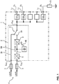
- Fig. 1 shows schematically a power distribution system 1 with an uninterruptible power supply, hereinafter referred to as UPS power supply 2, which or which is connected to an AC voltage network (L, N, PE) 4 via AC voltage inputs E AC and these fuses 3 arranged upstream in the exemplary embodiment.
- UPS power supply unit 2 has a converter path 2a and a bypass path 2b.
- a switchover device 5 for example in the form of a contactor or switching electronics, enables the switchover between the converter path 2a and the bypass path 2b and its connection to a load-side AC voltage output A AC of the UPS power supply unit 2.
- the converter path 2a of the UPS power supply unit 2 is essentially formed by a network-side AC-DC converter (rectifier) 6 and a DC intermediate circuit 7 downstream thereof and a DC-AC converter (inverter) 8 downstream thereof.
- a network-side AC-DC converter (rectifier) 6 and a DC intermediate circuit 7 downstream thereof and a DC-AC converter (inverter) 8 downstream thereof.
- DC intermediate circuit 7 is a battery or an accumulator 9 switched.
- the converter operation of the UPS power supply unit 2 is symbolized by the arrow labeled SB, while the battery operation of the UPS power supply unit 2, also referred to as autonomous operation, is symbolized by the arrow labeled AB.
- a load 10 which is led to the respective protective device GS m via a corresponding output A m of the power distribution system 1.
- the load 10 represents, for example, a device supplied by the power distribution system 1.
- thermo-magnetic one Trigger 12 In a triggering path 11 between the LINE input E L connected to the AC voltage output A AC and an output A L of the protective device GS m which is connected to the load output A n of the power distribution system 1 or forms it, is a thermo-magnetic one Trigger 12 and the switch contacts 14, 15 actuated by the latter via a switch lock 13.
- the key switch 13 can, for example, also be operated manually from the outside by means of a button or switching lever 16, that is, for example, switched on or triggered (ON / OFF).
- the trigger 12, the switch lock 13 and the switch contacts 14, 15 virtually form the electromechanical line or device circuit breaker of the protective device GS m .
- the protective device GS m has an electronic evaluation and release unit 17, hereinafter referred to as switch electronics or simply as electronics, which is integrated in the protective device GS m or assigned to it as an electronic module, for example also in a separate module housing.
- the electronics 17 is supplied with the load current I L flowing through the trigger path 11 of the protective device GS m and measured by a current sensor 18 as the actual current I ist .
- the current measurement is preferably carried out without contact and in particular inductively.
- the electronics 17 is also supplied with the output voltage U AC of the UPS power supply unit 2 as the actual voltage U ist, which is detected between the input E L and a further input E N of the protective device GS m by means of a voltage measuring device 19.
- the electronics 17 are supplied with voltage by means of a power supply unit 20 in the form of an AC-DC converter (rectifier), which is connected to the inputs E L and E N on the AC voltage side and to the electronics 17 on the DC voltage side.
- the electronics 17 are also fed via input inputs E 1 and E 2 a load or device-specific parameter P N indicating its nominal load and a parameter P max characterizing the maximum load of the UPS power supply unit 2 by corresponding parameter input.
- Current parameters I A or I B can also be entered directly into electronics 17
- the current value I A resulting from the input of the parameter P N determines the position of an in Fig. 4 shown electronic overload characteristic curve K UE or a corresponding characteristic curve range of the protective device GS m , while the input of the power supply-specific parameter P max or I B the position of an electronic short-circuit characteristic curve K K or a corresponding one Characteristic range determined for the UPS protection of the UPS power supply 2.
- the characteristic curve ranges K UE and K K form the in Fig. 4 shown electronic characteristic curve K E or the corresponding characteristic curve range of the protective device GS m .
- the presetting by means of the parameter P max or I B is suitably carried out using the data sheet for the UPS power supply 2 with regard to the short-circuit current.
- the electronics 17 supplies a display signal S A to an output A LED of the circuit breaker for controlling, for example, a light indicator (LED) or the like.
- a display signal S A to an output A LED of the circuit breaker for controlling, for example, a light indicator (LED) or the like.
- Fig. 3 illustrated in conjunction with the diagrams in Fig. 4 the triggering algorithm of the protective device GS m implemented in software 17 in the electronics.
- Fig. 4 showing in the right half of the figure in a time-flow diagram typical of the Einschaltkennline the load 10 during the actual current I is.
- power supply specific nominal and overload characteristic K UPS with a nominal and overload range K KSU (N) and K KSU (UE) and the course of the actual current I is are an electronic characteristic K K the electronics 17 as a short-circuit area and an electronic characteristic curve K UE of the electronics 17 as an overload area each illustrated in dashed lines.
- the B-tripping characteristic of the tripping device 12 of the protective device GS m as line and / or device protection is illustrated by the characteristic curve area K B with its thermal overload tripping area A t and its magnetic short-circuit tripping area A m .
- the characteristic curve labeled I S represents the melting current of the fuses 3 connected upstream of the UPS power supply unit 2.
- the electronic characteristic curve K UE for overload and the maximum load P max , I B des In the event of a short circuit, the UPS power supply unit 2 represents the electronic characteristic curve K K of the evaluation and tripping unit 17 of the protective device GS m .
- the illustrated algorithm is carried out in or by means of the electronics 17 on the one hand, using the implemented algorithm, a comparison of the detected actual current I ist with which the position of the UPS protection characteristic curve K UPS or the electronic characteristic curves K K for the short-circuit area indicating current parameter I B.
- U MIN can also be found in the standard DIN EN 62040-3 for the uninterruptible power supply and / or the data sheet of the UPS power supply 2.
- Figure 4 illustrates in the left half of the figure the voltage-time profile of the detected actual value U ist, the output voltage U AC as the characteristic profile of the UPS power supply unit 2 in battery operation AB.
- converter operation SB or with optional switchover to the bypass path 2b of the UPS power supply unit 2 there would be no voltage drop in the output voltage U AC of the UPS power supply unit 2 during the time interval ⁇ t, and thus the actual voltage U is not below the minimum or threshold value U MIN expected.
- the specified value U / U sol 100% without voltage drop in the time interval ⁇ t represents the corresponding characteristic curve in converter operation or bypass operation.
- the invention is not restricted to the exemplary embodiments described above. Rather, other variants of the invention can also be derived therefrom by the person skilled in the art without departing from the subject matter of the invention. In particular, all of them are also related to the exemplary embodiments individual features described can also be combined with one another in other ways without departing from the subject matter of the invention. For example, the number of connected load circuits of the power distribution system 1 can also be one (1).
Landscapes
- Engineering & Computer Science (AREA)
- Power Engineering (AREA)
- Stand-By Power Supply Arrangements (AREA)
- Breakers (AREA)
- Emergency Protection Circuit Devices (AREA)
- Protection Of Static Devices (AREA)
Description
- Die Erfindung betrifft ein Stromverteilungssystem zum Anschluss an ein Wechselspannungsnetz, mit einem Netzteil zur unterbrechungsfreien Stromversorgung mit einem netzseitigen Eingang und mit mindestens einem Ausgang, an welchem eine Anzahl von Lasten in parallelen Laststromkreisen angeschlossen oder anschließbar ist.
- Eine nachfolgend auch als USV-Netzteil bezeichnete Anlage oder Vorrichtung zur unterbrechungsfreien Stromversorgung (Uninterruptible Power Supply, UPS) wird im Netzbetrieb vom angeschlossenen (öffentlichen) Wechselspannungsnetz (AC-Netz) gestützt. An ein solches, beispielsweise aus der
EP 0419 015 A2 bekanntes USV-Netzteil angeschlossene Lasten werden entweder im Stromrichterbetrieb permanent über leistungselektronische Wandler oder bei üblicherweise nur kurzzeitigem Bypassbetrieb aus dem Wechselspannungsnetz direkt versorgt. Der Stromrichterbetrieb erfolgt über einen einem netzseitigen AC-DC-Wandler (Gleichrichter) nachgeschalteten und ausgangs- oder lastseitig einem DC-AC-Wandler (Wechselrichter) vorgeschalteten Gleichstromzwischenkreis, in den Pufferbatterien oder -akkumulatoren geschaltet sind. - Liegt eine Unterbrechung des öffentlichen Wechselspannungsnetzes vor, so wechselt das USV-Netzteil in den Batteriebetrieb und wird anschließend von der integrierten Pufferbatterie (Pufferakkumulator) für einen begrenzten Zeitraum versorgt. Bedingt durch die elektrischen Eigenschaften der in das USV-Netzteil integrierten Komponenten ist die im Batteriebetrieb des USV-Netzteils entnehmbare Leistung und damit auch der maximal fließende Strom begrenzt. Über gestaffelte Zeiträume von bis zu mehreren Minuten kann ein entsprechend gestaffelter Überstrom, der typischerweise auch größer als 100% des Nennstroms der angeschlossenen Last bzw. eines angeschlossenen Gerätes betragen kann, aus dem USV-Netzteil bezogen werden. Unter Nennstrom wird bei elektrischen Geräten (Lasten) die aufgenommene elektrische Stromstärke verstanden, wenn das Gerät (die Last) mit der Nennspannung versorgt wird und dessen Nennleistung abgibt.
- Für kürzere Zeiträume wird dabei ein höherer Überstrom zugelassen, als für längere Zeiträume. Normgemäß ist in Datenblättern derartiger USV-Netzteile der zeitlich begrenzte Maximalstrom (Maximallast) angegeben, über welchen die Ausgangsspannung des USV-Netzteils innerhalb der Grenzen nach DIN EN 62040-3 (Abs. 5.3.4) aufrechterhalten bleibt. Üblich ist ein Maximalstrom von 150% bis 200% des Nennstroms im Zeitraum weniger Sekunden bis einiger Minuten. Damit kann jedoch nur für kurze Zeit ein höherer Strom aus dem USV-Netzteil bezogen werden, etwa um Lasten bzw. Geräte einzuschalten.
- Weiterhin wird bei solchen USV-Netzteilen der spezifische maximale Kurzschlussstrom angegeben. Dieser liegt üblicherweise bei 200% bis 300% des Nennstroms für einige Millisekunden. Tritt im Batteriebetrieb des USV-Netzteils ein Kurzschluss innerhalb eines ausgangsseitig an das USV-Netzteil angeschlossenen Lastzweiges oder Laststromkreises auf, so ist der Kurzschlussstrom durch die Ausgangsleistung des USV-Netzteils limitiert. Dieser Kurzschlussstrom ist häufig nicht ausreichend, um einen klassischen Schutzschalter, insbesondere einen elektromechanischen Leitungsschutzschalter nach dem magnetischen Prinzip, also beispielsweise einen thermisch-magnetischen Schutzschalter, auszulösen. Infolgedessen würde die Leistungsgrenze des USV-Netzteils überschritten und demzufolge die Ausgangsspannung zusammenbrechen. Damit würde jedoch auch die Versorgung anderer, fehlerfreier Lastzweige bzw. Laststromkreise unterbrochen, indem das USV-Netzteil zum Selbstschutz ausschaltet und dabei deren Ausgangsspannung abschaltet. Ein selektives Abschalten lediglich eines fehlerbehafteten Lastzweiges oder Laststromkreises kann das USV-Netzteil nicht leisten.
- Ein Einschalten von Lasten genügt häufig bereits, um die Leistungsgrenze des USV-Netzteils zu überschreiten. Daher schaltet dieses selbständig in den Netzbetrieb (Bypassbetrieb) um. Der Einschaltstrom wird dann aus dem Wechselspannungsnetz gestützt und kann höhere Werte annehmen, als dies im Stromrichterbetrieb möglich ist. Die Ausgangsspannung des USV-Netzteils bleibt nun aufrechterhalten, wobei der Strom lediglich durch eine vorgeschaltete Schmelzsicherung oder durch eine lastzweigseitige Absicherung begrenzt wird, welche beim Überschreiten der jeweiligen Kennlinie entsprechend auslösen würde.
- Würde die Absicherung von an ein solches USV-Netzteil angeschlossenen Lasten (Geräten) durch Leitungsschutzschalter mit sogenannter B- oder C-Charakteristik (IEC 60898) realisiert, so würde die Absicherung typischerweise an den üblichen Installationsvorgaben für den Leitungsschutz im Haus- und Industriebetrieb orientiert sein. Da jedoch eine magnetische Auslösung eines solchen Leitungsschutzschalters im Batteriebetrieb nur dann erfolgen kann, wenn der Kurzschlussstrom des USV-Netzteils zur Auslösung des Leitungsschutzschalters ausreichend ist, müsste praktisch zwingend eine Überdimensionierung des USV-Netzteil vorgenommen werden, mit welcher der zur Auslösung des Leitungsschutzschalters benötigte Kurzschlussstrom geliefert werden kann, ohne dass das USV-Netzteil zum Selbstschutz vor Erreichen des entsprechenden Stromwertes ausschaltet und deren Ausgangsspannung abschaltet.
- Der Erfindung liegt daher die Aufgabe zugrunde, ein Stromverteilungssystem der eingangs genannten Art anzugeben, dass ein selektives Auslösen eines dem Netzteil zur unterbrechungsfreien Stromversorgung (USV-Netzteil) ausgangsseitig nachgeschalteten Schutzschalters im Überlast- und/oder Kurzschlussfall sicherstellt, ohne hierzu ein leistungsmäßig überdimensioniertes USV-Netzteil einzusetzen.
- Diese Aufgabe wird erfindungsgemäß gelöst durch ein Stromverteilungssystem mit den Merkmalen des Anspruchs 1. Vorteilhafte Ausgestaltungen und Weiterbildungen sin Gegenstand der Unteranasprüche.
- Hierzu umfasst das zum Anschluss an ein Wechselspannungsnetz vorgesehene Stromverteilungssystem ein Netzteil zur unterbrechungsfreien Stromversorgung (USV-Netzteil) mit einem netzseitigen Eingang und mit mindestens einem Ausgang, an welchen eine Anzahl von Lasten in parallelen Laststromkreisen angeschlossen oder anschließbar sind. In den oder jeden Laststromkreis ist ein Schutzgerät mit einem elektromechanischen, vorzugsweise thermisch-magnetischen, Auslöser und mit einer Auswerte- und Auslöseeinheit geschaltet. Die in das Schutzgerät integrierte oder diesem in Form eines Elektronikmoduls zugeordnete, vorzugsweise elektronische, Auswerte- und Auslöseeinheit betätigt das Schutzgerät bzw. löst dessen Auslöser anhand einer stromabhängigen Auslösecharakteristik in Form einer elektronischen Überlast- und/oder Kurschluss-Kennlinie und in Abhängigkeit von der Ausgangsspannung des USV-Netzteils aus. Das Schutzgerät bzw. dessen Auslöser weist geeigneterweise die thermisch-magnetischen Eigenschaften eines Leitungs- und/oder Geräteschutzschalter mit B- oder C-Charakteristik auf. Gemäß IEC 60898 wird unter B-Charakteristik der Standard-Leitungsschutz und unter C-Charakteristik ein Leitungsschutz für höhere Einschaltströme, wie beispielsweise bei Maschinen oder Lampengruppen, verstanden.
- In einer bevorzugten Ausgestaltung sind der Auswerte- und Auslöseeinheit die netzteilseitig, vorzugsweise im Schutzgerät, erfasste Ausgangsspannung des USV-Netzteils und der in einem Auslösepfad zwischen dem netzteilseitigen Ausgang des USV-Netzteils und einem Lastausgang des Schutzgerätes erfasste Strom zugeführt. Vorzugsweise löst die Auswerte- und Auslöseeinheit das Schutzgerät aus, wenn der erfasste Strom einen vorgegebenen Stromwert überschreitet und die erfasste Ausgangsspannung des USV-Netzteils einen vorgegebenen Spannungswert unterschreitet.
- Bei einem Netzausfall schaltet das USV-Netzteil bestimmungsgemäß in den Batteriebetrieb um, so dass ein Bypassbetrieb nun nicht mehr möglich ist. Sollte im Batteriebetrieb ein höherer Strom notwendig sein, als durch kurzzeitige Überlastung des USV-Netzteils möglich ist, kann diese noch für kurze Zeit einen begrenzten Kurzschlussstrom liefern. In diesem Fall ist jedoch nicht mehr sichergestellt, dass die Ausgangsspannung des USV-Netzteils innerhalb der Grenzen des sicheren Betriebs verbleibt. Unter Umständen liegen infolgedessen weitere Verbraucher an Unterspannung und schalten sich ab. Sollte der hohe Strom, z.B. durch Kurzschluss einer angeschlossenen Last im jeweiligen Lastkreis, weiterhin fließen, würde auch das USV-Netzteil wegen dauerhafter Überlastung abschalten.
- Die Erfindung geht von der Erkenntnis aus, dass durch die Kombination eines elektromechanischen, vorzugweise thermisch-magnetischen, Schutzgerätes, insbesondere eines Leitungsschutzschalters, mit einer Strom- und Spannungsauswertung eine Überdimensionierung des USV-Netzteils zur Erzeugung des erforderlichen Kurzschlussstroms bzw. des entsprechenden Stromwertes vermieden werden kann, indem nicht nur der aktuelle Laststrom (Ist-Strom) durch das Schutzgerät, sondern auch die Ausgangsspannung des USV-Netzteils erfasst und ausgewertet wird, welche netzteilseitige Ausgangsspannung gleichbedeutend mit der Spannung (Ist-Spannung) an der angeschlossenen Last ist.
- Da ein USV-Netzteil normgemäß, insbesondere entsprechend dem zugehörigen USV-Datenblatt, Angaben über den Maximal- und Kurzschlussstrom sowie über die Qualität der Spannungserhaltung enthält, können die einem Anwender somit direkt zugänglichen Werte in die vorzugsweise elektronische Auswerte- und Auslöseeinheit des Schutzgerätes eingegeben werden. Der somit für das USV-Netzteil spezifische Wert des Maximalstroms dient dem Abgleich des erfassten Ist-Stroms mit einer von der Eingabe des spezifischen Wertes abhängigen Kennlinie. Diese Maximallast- oder Maximalstrom-Kennlinie ist geeigneterweise derart gestaltet, dass deren Zeit-Strom-Wertepaare kleiner oder identisch der Bemessungswerte des USV-Netzteils im Batteriebetrieb sind.
- Wird diese eingestellte Kennlinie vom über das Schutzgerät, d. h. über dessen Auslösepfad fließenden Strom überschritten, so erfolgt die Auslösung des Schutzgerätes im betroffenen Lastkreis (Lastzweig) nur dann, wenn auch die erfasste Ausgangsspannung des USV-Netzteils des Stromverteilungssystems eine Spannungsgrenze bzw. einen Spannungsgrenzwert unterschreitet. Eine solche, wiederum in der DIN EN 62040-3 (Abs. 5.3.4) definierte Spannungsgrenze wird für das jeweils eingesetzte USV-Netzteil vorzugsweise ebenfalls der Auswerte- und Auslöseeinheit des vorzugsweise elektromechanischen Schutzgerätes als Spannungsgrenzwert für eine Maximallast zugeführt.
- Demnach wird bei jeder Überschreitung der einprogrammierten Kennlinie, insbesondere Strom-Kennlinie, unterschieden, ob sich das USV-Netzteil im Netzbetrieb oder im Batteriebetrieb befindet. Dabei kann im Netzbetrieb ein höherer Strom (Kurzschlussstrom) zugelassen werden, ohne dass eine Auslösung des Schutzgerätes und somit eine Trennung des entsprechenden Lastkreises erfolgt. Die Trennung des fehlerhaften Lastzweiges erfolgt normgemäß in einer ausreichenden Zeit, so dass die Spannungsversorgung der anderen, fehlerhaften Lastzweige des Stromverteilungssystems stets sichergestellt ist.
- Die Erfindung geht von der Überlegung aus, dass bei Einsatz lediglich eines klassischen bzw. normalen Leitungsschutzschalters im jeweiligen Laststromkreis eine genaue Schutzfunktion für die Absicherung der Last praktisch nicht hergestellt werden kann. Insbesondere für Lasten mit hohen Einschaltströmen ist die Verwendung von typischen Leitungsschutzschaltern denkbar ungeeignet, da die Spreizung zwischen Nennstrom und magnetischem Auslösestrom bei Leitungsschutzschaltern nicht zum Stromprofil dieser Lasten passt, selbst wenn ein solcher Leitungsschutzschalter mit C-Charakteristik verwendet wird.
- Alternativ oder vorteilhafterweise zusätzlich zum Maximalstrom des USV-Netzteils wird auch der Nennstrom (Nennlast) der angeschlossenen Last bzw. des angeschlossenen Gerätes eingegeben. Anhand dieser Eingabe in die Auswerte- und Auslöseeinheit des Schutzgerätes wird eine Überlast-Kennlinie gebildet, deren Zeit-Strom-Wertepaare kleiner als diejenigen des USV-Netzteils, jedoch größer als die der angeschlossenen Last bzw. des angeschlossenen Gerätes im Normalbetrieb sind. Die Kennlinien von Überlast und Maximallast treffen sich in einem gemeinsamen Punkt bzw. Kennlinienbereich. Bei einer Überschreitung der resultierenden Kennlinie erfolgt die daraufhin von der Auswerte- und Auslöseeinheit initiierte Auslösung des Schutzgerätes unverzüglich, wobei unabhängig von der elektronischen Auslösung die Eigenschaften des Leitungsschutzes des Schutzgerätes stets erhalten bleiben.
- Wird das USV-Netzteil über deren integrierten Stromrichter inklusive angeschlossenem Pufferakkumulator (Pufferbatterie) betrieben, so ist deren Leistungsfähigkeit begrenzt. Das Schutzgerät mit integrierter Auswerte- und Auslöseeinheit beinhaltet einen Leitungsschutzschalter, d. h. insbesondere einen thermisch-magnetischen Auslöser, und verfügt zusätzlich über eine elektronische Baugruppe als Auswerte- und Auslöseelektronik, welche die Überlastungssituation des USV-Netzteils detektiert und den Leitungsschutzschalter, d. h. den thermisch-magnetischen Auslöser entsprechend ansteuert, also quasi fernsteuert. Durch Eingabe zweier Stromparameter, nämlich eines Stromwertes (Stromgrenzwertes) zur Bestimmung der Lage der Geräte- bzw. Leitungsschutzkennlinie und eines Stromwertes (Stromgrenzwertes) zur Bestimmung der Lage der Geräte- bzw. Leitungsschutzkennlinie relativ zur USV-Überlastkennlinie in die Auswerte- und Auslöseeinheit des Schutzgerätes kann eine elektronische Kennlinie erzeugt werden.
- Grundlage der Überlastdetektion des USV-Netzteils ist vorzugsweise ein softwaretechnisch realisierter Algorithmus, der im Wesentlichen eine Überwachung der Überstromsituation vornimmt. Eine Überschreitung der elektronischen Kennlinie im Kurzschlussbereich wird nur toleriert, wenn auch die Ausgangsspannung des USV-Netzteils noch aufrechterhalten bleibt. Wenn sowohl der Überstrom den Maximalstrom des USV-Netzteils im Batteriebetrieb überschritten hat, also auch die Ausgangsspannung des USV-Netzteils nicht mehr dem ordnungsgemäßen Betrieb entspricht, erfolgt eine Auslösung des Schutzschalters.
- Ist das USV-Netzteil noch vom Wechselspannungsnetz versorgt, kann ein höherer Strom zum Einschalten über den Bypass bezogen werden. Das Schutzgerät wird hierbei nicht auslösen, weil der Auslösefall gemäß dem Algorithmus nicht aufgetreten ist. Im Kurzschlussfall kann der integrierte elektromechanische Auslöser des Schutzgerätes normal auslösen.
- Ist hingegen das Wechselspannungsnetz ausgefallen, so fließt in diesem Fall aufgrund des Einschaltens der Last oder aufgrund eines Kurzschlusses im entsprechenden Lastkreis ein Strom, der an die Überlastgrenzen des USV-Netzteils heran reicht. Dies wirkt sich auf die Ausgangsspannung des USV-Netzteils aus, so dass somit ein Auslösefall gemäß dem Algorithmus vorliegt und die Trennung (Auslösung) durch den Schutzschalter erfolgt.
- Auch kann der Effektivwert des Laststroms innerhalb ausgewählter Zeitintervalle berechnet und dahingehend geprüft werden, ob der Effektivwert des Stromes die Überlastkennlinie überschreitet. Überschreitet der Laststrom die Kennlinie eines der Intervalle, so erfolgt eine Auslösung des Schutzschalters.
- Nachfolgend werden Ausführungsbeispiele der Erfindung anhand einer Zeichnung näher erläutert. Darin zeigen:
- Fig. 1
- schematisch ein an ein Wechselspannungsnetz angeschlossenes Stromverteilungssystem mit einer Anzahl von mittels eines USV-Netzteils unterbrechungsfreie versorgten Lastkreisen mit jeweils einem elektromechanischen Schutzschalter zum Schutz gegen Überlast und Kurzschluss,
- Fig. 2
- schematisch den Schutzschalter mit thermisch-magnetischem Auslöser sowie mit einer Auswerte- und Auslöseeinheit (Elektronik) und mit einer Strom- und Spannungsmessung,
- Fig. 3
- schematisch einen in die Auswerte- und Auslöseeinheit implementierten Algorithmus zur Bestimmung eines Auslösefalls, und
- Fig. 4
- den elektronischen und B-charakteristischen Kennlinienverlauf des Schutzschalters bei Batteriebetrieb des USV-Netzteils,
- Einander entsprechende Teile sind in allen Figuren mit den gleichen Bezugszeichen versehen.
-
Fig. 1 zeigt schematisch ein Stromverteilungssystem 1 mit einer nachfolgend als USV-Netzteil 2 bezeichneten unterbrechungsfreien Stromversorgung, welches bzw. welche über Wechselspannungseingänge EAC und diesen im Ausführungsbeispiel vorgeordneten Schmelzsicherungen 3 an ein Wechselspannungsnetz (L,N,PE) 4 angeschlossen ist. Das USV-Netzteil 2 weist einen Stromrichterpfad 2a und einen Bypasspfad 2b auf. Eine Umschalteinrichtung 5, beispielsweise in Form eines Schaltschützes oder einer Schaltelektronik, ermöglicht die Umschaltung zwischen dem Stromrichterpfad 2a und dem Bypasspfad 2b sowie deren Aufschaltung auf einen lastseitigen Wechselspannungsausgang AAC des USV-Netzteils 2. - Der Stromrichterpfad 2a des USV-Netzteils 2 ist im Wesentlichen gebildet durch einen netzseitigen AC-DC-Wandler (Gleichrichter) 6 und einen diesem nachgeordneten Gleichstromzwischenkreis 7 sowie einem diesem wiederum nachgeordneten DC-AC-Wandler (Wechselrichter) 8. In den Gleichstromzwischenkreis 7 ist eine Batterie bzw. ein Akkumulator 9 geschaltet. Der Stromrichterbetrieb des USV-Netzteils 2 ist durch den mit SB bezeichneten Pfeil symbolisiert, während der auch als autonomer Betrieb bezeichnete Batteriebetrieb des USV-Netzteils 2 mit dem mit AB bezeichneten Pfeil symbolisiert ist.
- An den Wechselspannungsausgang AAC des USV-Netzteils 2 sind eine Anzahl von Laststromkreisen Lm mit m = 1, 2, ..., n zueinander parallel angeschlossen. Im Ausführungsbeispiel ist in jeden Laststromkreis Lm ein elektromechanisches Schutzgerät GSm mit m = 1, 2, ..., n, insbesondere ein thermisch-magnetischer Leitungsschutzschalter mit B-Charakteristik, geschaltet. In dem oder jedem Laststromkreis Lm befindet sich eine Last 10, welche über einen entsprechenden Ausgang Am des Stromverteilungssystems 1 an das jeweilige Schutzgerät GSm geführt ist. Die Last 10 repräsentiert beispielsweise ein von dem Stromverteilungssystem 1 versorgtes Gerätes.
- Den Aufbau bzw. die Funktionskomponenten des jeweiligen elektromechanischen Schutzgerätes GSm zeigt
Fig. 2 . In einem Auslösepfad 11 zwischen dem mit dem Wechselspannungsausgang AAC verbundenen LINE-Eingang EL und einem an den Lastausgang An des Stromverteilungssystems 1 geführten oder diesen bildenden Ausgang AL des Schutzgerätes GSm sind ein thermisch-magnetischer Auslöser 12 und die von diesem über ein Schaltschloss 13 betätigten Schaltkontakte 14, 15 geschaltet. Das Schaltschloss 13 kann beispielsweise auch mittels eines Tasters oder Schalthebels 16 von außen manuell betätigt, also beispielsweise eingeschaltet oder ausgelöst (EIN/AUS) werden. Der Auslöser 12, das Schaltschloss 13 und die Schaltkontakte 14, 15 bilden quasi den elektromechanischen Leitungs- bzw. Geräteschutzschalter des Schutzgerätes GSm. - Das Schutzgerät GSm weist eine nachfolgend als Schalterelektronik oder einfach als Elektronik bezeichnete elektronische Auswerte- und Auslöseeinheit 17 auf, die in das Schutzgerät GSm integriert oder diesem als Elektronikmodul, beispielsweise auch in einem separaten Modulgehäuse, zugeordnet ist. Der Elektronik 17 wird der über den Auslösepfad 11 des Schutzgerätes GSm fließende und von einem Stromsensor 18 gemessene Laststrom IL als Ist-Strom Iist zugeführt. Die Strommessung erfolgt vorzugsweise berührungslos und insbesondere induktiv. Der Elektronik 17 wird zudem die zwischen dem Eingang EL und einem weiteren Eingang EN des Schutzgerätes GSm mittels einer Spannungs-Messeinrichtung 19 erfasste Ausgangsspannung UAC des USV-Netzteils 2 als Ist-Spannung Uist zugeführt.
- Die Spannungsversorgung der Elektronik 17 erfolgt mittels eines Netzteils 20 in Form eines AC-DC-Wandlers (Gleichrichter), der wechselspannungsseitig an die Eingänge EL und EN sowie gleichspannungsseitig mit der Elektronik 17 verbunden ist. Der Elektronik 17 werden zudem über Eingabeeingänge E1 und E2 ein last- bzw. gerätespezifischer und dessen Nennlast angebender Parameter PN und ein die Maximallast des USV-Netzteils 2 charakterisierender Parameter Pmax durch entsprechende Parametereingabe zugeführt. Auch können direkt Stromparameter IA bzw. IB in die Elektronik 17 eingegeben werden
- Der aus der Eingabe des Parameters PN resultierende oder direkt eingegebene Stromwert IA bestimmt die Lage einer in
Fig. 4 gezeigten elektronischen Überlast-Kennlinie KUE bzw. eines entsprechenden Kennlinienbereiches des Schutzgerätes GSm, während die Eingabe des netzteilspezifischen Parametes Pmax bzw. IB die Lage einer elektronischen Kurschluss-Kennlinie KK bzw. eines entsprechenden Kennlinienbereiches für den USV-Schutz des USV-Netzteils 2 bestimmt. Die Kennlinienbereiche KUE und KK bilden die inFig. 4 gezeigte elektronische Kennlinie KE bzw. den entsprechenden Kennlinienbereich des Schutzgerätes GSm. Die Voreinstellung mittels des Parameters Pmax bzw. IB erfolgt geeigneterweise anhand des Datenblattes für das USV-Netzteil 2 bezüglich des Kurzschlussstroms. - Die Elektronik 17 liefert im Ausführungsbeispiel ein Anzeigesignal SA an einen Ausgang ALED des Schutzschalters zur Ansteuerung beispielsweise einer Leuchtanzeige (LED) oder dergleichen.
-
Fig. 3 veranschaulicht in Verbindung mit den Diagrammen inFig. 4 den softwaremäßig in die Elektronik 17 implementierten Auslösealgorithmus des Schutzgerätes GSm.Fig. 4 zeigt in der rechten Figurenhälfte in einem Zeit-Strom Diagramm den für die Einschaltkennlinie der Last 10 typischen Verlauf des Ist-Stromes list. Zwischen einer für das USV-Netzteil 2 typischen, netzteilspezifischen Nenn- und Überlastkennlinie KUSV mit einem Nenn- und Überlastbereich KKSU(N) bzw. KKSU(UE) und dem Verlauf des Ist-Stromes Iist sind eine elektronische Kennlinie KK der Elektronik 17 als Kurzschlussbereich und eine elektronische Kennlinie KUE der Elektronik 17 als Überlastbereich jeweils gestrichelt veranschaulicht. Die B-Auslösecharakteristik des Auslösers 12 des Schutzgerätes GSm als Leitungs- und/oder Geräteschutzes veranschaulicht der Kennlinienbereich KB mit dessen thermischem Überlast-Auslösebereich At und dessen magnetischem Kurzschluss-Auslösebereich Am. Die mit IS bezeichnete Kennlinie repräsentiert den Schmelzstrom der dem USV-Netzteil 2 vorgeschalteten Schmelzsicherungen 3. In dem mit KKUE bezeichneten Punkt oder Kennlinien- oder Übergangsbereich treffen sich die elektronische Kennlinie KUE für Überlast und die die Maximallast Pmax, IB des USV-Netzteils 2 im Kurzschlussfall repräsentierende elektronische Kennlinie KK der Auswerte- und Auslöseeinheit 17 des Schutzgerätes GSm. - Mit dem Beginn (Start) des Prüfzyklus des in
Fig. 3 veranschaulichten Algorithmus erfolgt in oder mittels der Elektronik 17 anhand des implementierten Algorithmus einerseits ein Vergleich des erfassten Ist-Stroms Iist mit dem die Lage der USV-Schutz-Kennlinie KUSV bzw. die elektronische Kennlinien KK für den Kurschlussbereich angebenden Stromparameter IB. Zudem kann ein Vergleich des zeitlichen Verlaufs der Ist-Spannung Uist der erfassten Ausgangsspannung UAC des USV-Netzteils 2 mit einem aus dem Parameter Pmax für die Maximallast des USV-Netzteils 2 abgeleiteten Spannungswertes UMIN erfolgen (UMIN = Pmax/IB). UMIN kann auch der Norm DIN EN 62040-3 für die unterbrechungsfreie Stromversorgung und/oder dem Datenblatt des USV-Netzteils 2 entnommen werden. - Überschreitet während eines in
Fig. 4 veranschaulichten Zeitintervalls Δt für eine maximale Zeitdauer Δt ≥ tmax, mit beispielsweise tmax = 1 ms, der erfasste Ist-Strom Iist den durch den Stromparameter oder Stromwert IB vorgegebenen Kennlinienbereich KK, KUSV und unterschreitet hierbei die erfasste Ist-Spannung Uist und damit die Ausgangsspannung UAC des USV-Netzteils 2 den vorgegebenen Spannungs- bzw. Minimalwert UMIN, so erfolgt die Auslösung des Schutzgeräte GSm durch entsprechendes Öffnen der Schaltkontakte 14, 15 infolge einer entsprechenden Auslösung (Aus) des Auslösers 12 direkt oder indirekt über das Schaltschloss 13 aufgrund einer entsprechenden Initiierung durch die bzw. von der Elektronik 17. Andernfalls wird auf einen mit u bezeichneten unkritischen Betrieb erkannt. -
Fig.4 veranschaulicht in der linken Figurenhälfte den Spannungs-Zeit-Verlauf des erfassten Ist-Wertes Uist der Ausgangsspannung UAC als Kennlinienverlauf des USV-Netzteils 2 im Batteriebetrieb AB. Im Stromrichterbetrieb SB bzw. bei optionaler Umschaltung auf den Bypasspfad 2b des USV-Netzteils 2 wäre während des Zeitintervalls Δt kein Spannungseinbruch der Ausgangsspannung UAC des USV-Netzteils 2 und somit kein Unterschreiten der Ist-Spannung Uist unter den Minimal- oder Schwellwert UMIN zu erwarten. Der angegebene Wert U/Usol = 100% ohne Spannungseinbruch im Zeitintervall Δt repräsentiert die entsprechende Kennlinie bei Stromrichterbetrieb oder Bypassbetrieb. - Die Erfindung ist nicht auf die vorstehend beschriebenen Ausführungsbeispiele beschränkt. Vielmehr können auch andere Varianten der Erfindung von dem Fachmann hieraus abgeleitet werden, ohne den Gegenstand der Erfindung zu verlassen. Insbesondere sind ferner alle im Zusammenhang mit den Ausführungsbeispielen beschriebenen Einzelmerkmale auch auf andere Weise miteinander kombinierbar, ohne den Gegenstand der Erfindung zu verlassen. So kann beispielsweise die Anzahl der angeschlossenen Lastkreise des Stromverteilungssystems 1 auch eins (1) betragen.
-
- 1
- Stromverteilungssystem
- 2
- Netzteil/USV
- 2a
- Bypass
- 2b
- Stromrichter
- 3
- Schmelzsicherung
- 4
- Wechselspannungsnetz
- 5
- Wechselschalter/Schaltschütz
- 6
- AC/DC-Wandler
- 7
- Gleichstromzwischenkreis
- 8
- DC/AC-Wandler
- 9
- Batterie-Akkumulator
- 10
- Gerät/Last
- 11
- Auslösepfad
- 12
- thermisch-magnetischer Auslöser
- 13
- Schaltschloss
- 14
- Schaltkontakt
- 15
- Schaltkontakt
- 16
- Taster/Schalthebel
- 17
- Auslöse-/Auswerteeinheit / Elektronik
- 18
- Stromsensor
- 19
- Messvorrichtung
- 20
- Netzteil
- AB
- Batteriebetrieb
- AAC
- Wechselspannungsausgang
- ALED
- Ausgang
- An
- Lastausgang
- Am
- Kurzschluss-Auslösebereich
- At
- Überlast-Auslösebereich
- EL
- LINE-Eingang
- EN
- N-Eingang
- E1
- Nennlast-Eingabeeingang
- E2
- Maximallast-Eingabeeingang
- GSm
- Schutzgerät
- IA
- Nennlast-Stromwert/-parameter
- IB
- Maximallast-Stromwert/-parameter
- IL
- Laststrom
- Iist
- Ist-Strom
- IS
- Schmelzstrom-Kennlinie
- KUSV
- USV-Kennlinie
- KB
- Kennlinienbereich
- KE
- elektronische Kennlinie/-bereich
- KK
- Kurzschlusskennlinie/-bereich
- KUE
- Überlastkennlinie/-bereich
- KKUE
- Übergangsbereich/Punkt
- Lm
- Laststromkreisen
- UMIN
- Spannungs-/Minimalwert
- Uist
- Ist-Spannung
- UAC
- Ausgangsspannung
- SB
- Stromrichterbetrieb
- SA
- Anzeigesignal
- PN
- Nennlast-Parameter
- Pmax
- Maximallast-Parameter
Claims (8)
- Stromverteilungssystem (1) zum Anschluss an ein Wechselspannungsnetz (4), mit einem USV-Netzteil (2) zur unterbrechungsfreien Stromversorgung mit einem netzseitigen Eingang (EAC) und mit mindestens einem Ausgang (AAC), an welchen eine Anzahl von Lasten (10) in parallelen Laststromkreisen (Lm) anschließbar sind,
dadurch gekennzeichnet,- dass in den oder jeden Laststromkreis (Lm) ein Schutzgerät (GSm) mit einem elektromechanischen Auslöser (12) und mit einer Auswerte- und Auslöseeinheit (17) geschaltet ist, welche anhand einer elektronischen Überlastkennlinie (KE, KUE) und/oder einer Kurschluss-Kennlinie (KE, KK) sowie in Abhängigkeit von der Ausgangsspannung (UAC, Uist) des USV-Netzteils (2) den Auslöser (12) betätigt und das Schutzgerät (GSm) auslöst,- dass das Schutzgerät (GSm) einen Eingang (E2) zur Eingabe eines die Maximallast des USV-Netzteils (2) repräsentierenden Parameters (Pmax, IB) in die Auswerte- und Auslöseeinheit (17) aufweist, wobei der die Maximallast des USV-Netzteils (2) repräsentierende Parameter (Pmax, IB) zum Abgleich des erfassten Ist-Stroms (Iist) mit einer von diesem Parameter (Pmax, IB) abhängigen Überlast-Kennlinie (KUSV) des USV-Netzteils (2) dient, und/oder- dass das Schutzgerät (GSm) einen Eingang (E1) zur Eingabe eines die Nennlast der angeschlossenen Last (10) repräsentierenden Parameters (PN, IA) in die Auswerte- und Auslöseeinheit (17) aufweist. - Stromverteilungssystem (1) nach Anspruch 1,
dadurch gekennzeichnet,
dass der Auswerte- und Auslöseeinheit (17) die netzteilseitig erfasste Ausgangsspannung (UAC, Uist) des USV-Netzteils (2) und der in einem Auslösepfad (11) zwischen dem netzteilseitigen Ausgang (EL, AAC) und einem Lastausgang (AL, Am) des Schutzgerätes (GSm) erfasste Strom (IL, Iist) zugeführt sind. - Stromverteilungssystem (1) nach Anspruch 2,
dadurch gekennzeichnet,
dass die Auswerte- und Auslöseeinheit (17) das Schutzgerät (GSm) auslöst, wenn der erfasste Strom (Iist) einen vorgegebenen Stromwert (IB) überschreitet und die erfasste Ausgangsspannung (UAC, Uist) des USV-Netzteils (2) einen vorgegebenen Spannungswert (UMIN) unterschreitet. - Stromverteilungssystem (1) nach einem der Ansprüche 1 bis 3,
dadurch gekennzeichnet,
dass die Auswerte- und Auslöseeinheit (17) anhand des eingegebenen, die Maximallast des USV-Netzteils (2) repräsentierenden Parameters (Pmax, IB) und/oder des eingegebenen, die Nennlast der angeschlossenen Last (10) repräsentierenden Parameters (PN, IA) die elektronische Kennlinie (KUE, KK) eines Überlastbereiches bzw. eines Kurzschlussbereiches bildet, deren Zeit-Strom-Wertepaare kleiner als diejenigen der Überlast-Kennlinie (KUSV) des USV-Netzteils (2), jedoch größer als diejenigen der angeschlossenen Last (Lm) bzw. des angeschlossenen Gerätes im Normal- oder Nennlastbetrieb sind. - Stromverteilungssystem (1) nach einem der Ansprüche 1 bis 4,
dadurch gekennzeichnet,
dass eine Auslösung des Schutzgerätes (GSm) im betroffenen Laststromkreisen (Lm) nur dann erfolgt, wenn bei Überschreiten der Überlast-Kennlinie (KUSV) des USV-Netzteils (2) durch den erfassten Ist-Stroms (list) die erfasste Ausgangsspannung (UAC, Uist) des Netzteils (2) einen Spannungsgrenzwert (UMIN) unterschreitet. - Stromverteilungssystem (1) nach einem der Ansprüche 1 bis 5,
dadurch gekennzeichnet,
dass sich die elektronische Kennlinie (KUE) für Überlast und die die Maximallast (Pmax, IB) des USV-Netzteils (2) im Kurzschlussfall repräsentierende elektronische Kennlinie (KK) der Auswerte- und Auslöseeinheit (17) des Schutzgerätes (GSm) in einem Kennlinienbereich (KKUE) treffen. - Stromverteilungssystem (1) nach Anspruch 6,
dadurch gekennzeichnet,
dass bei einer Überschreitung der elektronischen Kennlinie (KE, KUE) für Überlast und/oder der elektronischen Kennlinie (KE, KK) im Kurzschlussfall die von der Auswerte- und Auslöseeinheit (17) initiierte Auslösung des Schutzgerätes (GSm) erfolgt. - Stromverteilungssystem (1) nach einem der Ansprüche 1 bis 7,
dadurch gekennzeichnet,
dass die elektronischen Kennlinien (KE, KK) der Auswerte- und Auslöseeinheit (17) denjenigen maximal möglichen Laststrom (IL) im Stromrichterbetrieb (SB) des USV-Netzteils (2) repräsentiert, bei welchem dessen Ausgangsspannung (UAC) einen definierten Spannungsgrenzwert (UMIN) nicht unterschreitet.
Applications Claiming Priority (2)
| Application Number | Priority Date | Filing Date | Title |
|---|---|---|---|
| DE102015004633.0A DE102015004633B4 (de) | 2015-04-10 | 2015-04-10 | Stromverteilungssystem zum Anschluss an ein Wechselspannungsnetz |
| PCT/EP2016/057101 WO2016162266A1 (de) | 2015-04-10 | 2016-03-31 | Stromverteilungssystem zum anschluss an ein wechselspannungsnetz |
Publications (2)
| Publication Number | Publication Date |
|---|---|
| EP3281267A1 EP3281267A1 (de) | 2018-02-14 |
| EP3281267B1 true EP3281267B1 (de) | 2019-12-25 |
Family
ID=55755566
Family Applications (1)
| Application Number | Title | Priority Date | Filing Date |
|---|---|---|---|
| EP16716836.8A Active EP3281267B1 (de) | 2015-04-10 | 2016-03-31 | Stromverteilungssystem zum anschluss an ein wechselspannungsnetz |
Country Status (6)
| Country | Link |
|---|---|
| US (1) | US10411457B2 (de) |
| EP (1) | EP3281267B1 (de) |
| JP (1) | JP6532956B2 (de) |
| CN (1) | CN107438930B (de) |
| DE (2) | DE102015004633B4 (de) |
| WO (1) | WO2016162266A1 (de) |
Families Citing this family (4)
| Publication number | Priority date | Publication date | Assignee | Title |
|---|---|---|---|---|
| DE102017115798A1 (de) | 2017-07-13 | 2019-01-17 | Alanod Gmbh & Co. Kg | Reflektierendes Verbundmaterial, insbesondere für oberflächenmontierte Bauelemente (SMD), und lichtemittierende Vorrichtung mit einem derartigen Verbundmaterial |
| CN110034546B (zh) * | 2019-03-07 | 2021-06-04 | 中国人民解放军海军工程大学 | 逆变器与发电机并联供电的低压交流配电网短路保护方法 |
| CN118801556A (zh) * | 2021-06-25 | 2024-10-18 | 漳州科华技术有限责任公司 | 一种基于负载短路的ups供电方法及ups |
| US11489362B1 (en) | 2022-03-10 | 2022-11-01 | Enconnex LLC | Uninterruptable power supply with supplemental power apportionment |
Family Cites Families (19)
| Publication number | Priority date | Publication date | Assignee | Title |
|---|---|---|---|---|
| US3714452A (en) * | 1972-02-07 | 1973-01-30 | Gen Electric | Circuit breaker monitor for uninterruptable power systems including a static bypass |
| JP2695941B2 (ja) * | 1989-09-22 | 1998-01-14 | 株式会社東芝 | 無停電電源装置 |
| CN2085979U (zh) * | 1990-10-09 | 1991-10-02 | 中国建筑材料科学研究院水泥科学研究所 | 数字移相式晶闸管程控调压器 |
| DE4033444C2 (de) * | 1990-10-20 | 1994-01-13 | Veba Kraftwerke Ruhr | Überstrom-Schutzeinrichtung für mittels Notstromversorgungen gespeiste Netze |
| CN1032995C (zh) * | 1993-09-09 | 1996-10-09 | 魏有辑 | 三相异步电动机保护器 |
| DE19749698A1 (de) * | 1997-10-28 | 1999-04-29 | Siemens Ag | Schutzschaltungsanordnung für ein Energieverteilungsnetz |
| EP0978920A1 (de) * | 1998-08-04 | 2000-02-09 | Lucent Technologies Inc. | Stromversorgungssystem |
| DE29909206U1 (de) | 1999-05-28 | 2000-10-05 | Ellenberger & Poensgen | Schutzeinrichtung |
| US7236338B2 (en) * | 2003-09-16 | 2007-06-26 | The Boeing Company | System and method for remotely detecting and locating faults in a power system |
| DE102004046810A1 (de) * | 2004-09-17 | 2006-04-06 | Hidde, Axel R., Dr.-Ing. | Elektronischer Schutzschalter mit einstellbarer Auslösecharakteristik |
| DE202004014580U1 (de) * | 2004-09-17 | 2004-12-09 | Hidde, Axel R., Dr.-Ing. | Elektronischer Schutzschalter mit einstellbarer Auslöse-Charakteristik |
| DE102005031833B4 (de) | 2005-07-06 | 2017-01-05 | Phoenix Contact Gmbh & Co. Kg | Verfahren und elektronische Stromversorgungsvorrichtung zur Energieversorgung einer durch eine Schutzeinrichtung gesicherten Niederspannungslast |
| DE102006042768A1 (de) * | 2005-09-15 | 2007-03-29 | Siemens Ag | Verfahren zum Betreiben eines elektrischen Schutzschalters und nach diesem Verfahren betriebener elektrischer Schutzschalter |
| GB2443002A (en) * | 2006-10-16 | 2008-04-23 | Converteam Ltd | dc power distribution system |
| JP4615571B2 (ja) * | 2008-01-18 | 2011-01-19 | 中部電力株式会社 | 低圧電力契約用遮断器 |
| US8395873B2 (en) * | 2010-06-09 | 2013-03-12 | Hamilton Sundstrand Corporation | SSPC with dual fault detectors |
| CN103208773A (zh) * | 2013-04-10 | 2013-07-17 | 上海电器科学研究院 | 一种船舶用中压真空断路器智能脱扣器 |
| DE102013105942A1 (de) * | 2013-06-07 | 2014-12-11 | Murrelektronik Gmbh | Verfahren zur Steuerung eines Schutzschalters, sowie Schutzschalter |
| US9876343B2 (en) * | 2015-01-29 | 2018-01-23 | Eaton Corporation | Transfer switch including management system and associated method |
-
2015
- 2015-04-10 DE DE102015004633.0A patent/DE102015004633B4/de active Active
- 2015-04-10 DE DE202015009409.0U patent/DE202015009409U1/de not_active Expired - Lifetime
-
2016
- 2016-03-31 JP JP2017548184A patent/JP6532956B2/ja active Active
- 2016-03-31 EP EP16716836.8A patent/EP3281267B1/de active Active
- 2016-03-31 WO PCT/EP2016/057101 patent/WO2016162266A1/de not_active Ceased
- 2016-03-31 CN CN201680020706.1A patent/CN107438930B/zh active Active
-
2017
- 2017-10-10 US US15/729,074 patent/US10411457B2/en active Active
Non-Patent Citations (1)
| Title |
|---|
| None * |
Also Published As
| Publication number | Publication date |
|---|---|
| CN107438930A (zh) | 2017-12-05 |
| US20180034260A1 (en) | 2018-02-01 |
| DE202015009409U1 (de) | 2017-06-30 |
| WO2016162266A1 (de) | 2016-10-13 |
| JP6532956B2 (ja) | 2019-06-19 |
| DE102015004633B4 (de) | 2017-07-13 |
| CN107438930B (zh) | 2019-07-23 |
| EP3281267A1 (de) | 2018-02-14 |
| JP2018518006A (ja) | 2018-07-05 |
| US10411457B2 (en) | 2019-09-10 |
| DE102015004633A1 (de) | 2016-10-13 |
Similar Documents
| Publication | Publication Date | Title |
|---|---|---|
| DE102016218960B4 (de) | Schalter | |
| DE102020216405B4 (de) | Verfahren zum Ansteuern eines Leistungshalbleiterschalters, Ansteuerschaltung für einen Leistungshalbleiterschalter sowie elektronischer Schutzschalter | |
| DE102017215820B4 (de) | Leistungsschalter und Verfahren | |
| DE102016202827B4 (de) | Leistungsschalter | |
| DE102008053074A1 (de) | Schnellschalteinrichtung für eine Hochleistungs-Batterie in einem Gleichstrominselnetz | |
| EP3281267B1 (de) | Stromverteilungssystem zum anschluss an ein wechselspannungsnetz | |
| DE102015105476A1 (de) | Verfahren und Vorrichtung zur Energieversorgung einer Niederspannungslast | |
| DE102020216397B3 (de) | Schutzschaltgerät und Verfahren | |
| EP4356409A1 (de) | Schutzschaltgerät | |
| DE102015000576B4 (de) | Kraftfahrzeug mit Schaltvorrichtung für eine bordnetzbetriebene Komponente | |
| DE102017220711A1 (de) | Schutzvorrichtung sowie Verfahren zum Betrieb einer solchen Schutzvorrichtung | |
| DE102013225732A1 (de) | Hochvolt-Sicherung für Fahrzeuge | |
| EP4367700A1 (de) | Schutzschaltgerät | |
| EP2500208A2 (de) | Schutzschaltungsanordnung | |
| BE1026349A1 (de) | Schutzschalter mit Überwachungseinrichtung und Verfahren hierfür | |
| DE102018211646B4 (de) | Niederspannungsleistungsschalter und Verfahren | |
| DE102016006022B3 (de) | Schutzeinrichtung und Verfahren zum Schutz bei einem elektrischen Kurzschluss | |
| DE102015115284B3 (de) | Schutzvorrichtung für eine elektrische Energieversorgungseinrichtung und elektrische Energieversorgungseinrichtung mit einer derartigen Schutzvorrichtung | |
| EP2672595B1 (de) | Schaltungsanordnung und Verfahren zur Gleichstromunterbrechung | |
| DE102021109645A1 (de) | Energieversorgungsvorrichtung mit sicherheitsgerichteter Abschaltung sowie Verfahren zum Abschalten einer Energieversorgungsvorrichtung | |
| DE102018218461B4 (de) | Schutzensemble | |
| LU506789B1 (de) | Elektronische Sicherung zum Vermeiden eines unerwünschten dauerhaften Abschaltens von elektrischen Verbrauchern bei Überlastverhalten | |
| EP3467982B1 (de) | Energieversorgungsvorrichtung | |
| EP1735887B1 (de) | Fehlerstromschutzschalter | |
| EP1403994A1 (de) | Niederspannungs-Leistungsschalter mit zusätzlicher Schnellauslösung |
Legal Events
| Date | Code | Title | Description |
|---|---|---|---|
| STAA | Information on the status of an ep patent application or granted ep patent |
Free format text: STATUS: THE INTERNATIONAL PUBLICATION HAS BEEN MADE |
|
| PUAI | Public reference made under article 153(3) epc to a published international application that has entered the european phase |
Free format text: ORIGINAL CODE: 0009012 |
|
| STAA | Information on the status of an ep patent application or granted ep patent |
Free format text: STATUS: REQUEST FOR EXAMINATION WAS MADE |
|
| 17P | Request for examination filed |
Effective date: 20171107 |
|
| AK | Designated contracting states |
Kind code of ref document: A1 Designated state(s): AL AT BE BG CH CY CZ DE DK EE ES FI FR GB GR HR HU IE IS IT LI LT LU LV MC MK MT NL NO PL PT RO RS SE SI SK SM TR |
|
| AX | Request for extension of the european patent |
Extension state: BA ME |
|
| RIN1 | Information on inventor provided before grant (corrected) |
Inventor name: HARRER, HUBERT Inventor name: PHAM, THANH-HUY Inventor name: ZEBERL, JUERGEN Inventor name: FISCHER, ERICH Inventor name: REGAHL, THOMAS |
|
| DAV | Request for validation of the european patent (deleted) | ||
| DAX | Request for extension of the european patent (deleted) | ||
| GRAP | Despatch of communication of intention to grant a patent |
Free format text: ORIGINAL CODE: EPIDOSNIGR1 |
|
| STAA | Information on the status of an ep patent application or granted ep patent |
Free format text: STATUS: GRANT OF PATENT IS INTENDED |
|
| INTG | Intention to grant announced |
Effective date: 20190809 |
|
| GRAS | Grant fee paid |
Free format text: ORIGINAL CODE: EPIDOSNIGR3 |
|
| GRAA | (expected) grant |
Free format text: ORIGINAL CODE: 0009210 |
|
| STAA | Information on the status of an ep patent application or granted ep patent |
Free format text: STATUS: THE PATENT HAS BEEN GRANTED |
|
| AK | Designated contracting states |
Kind code of ref document: B1 Designated state(s): AL AT BE BG CH CY CZ DE DK EE ES FI FR GB GR HR HU IE IS IT LI LT LU LV MC MK MT NL NO PL PT RO RS SE SI SK SM TR |
|
| REG | Reference to a national code |
Ref country code: GB Ref legal event code: FG4D Free format text: NOT ENGLISH |
|
| REG | Reference to a national code |
Ref country code: CH Ref legal event code: EP |
|
| REG | Reference to a national code |
Ref country code: AT Ref legal event code: REF Ref document number: 1218184 Country of ref document: AT Kind code of ref document: T Effective date: 20200115 |
|
| REG | Reference to a national code |
Ref country code: DE Ref legal event code: R096 Ref document number: 502016008137 Country of ref document: DE |
|
| REG | Reference to a national code |
Ref country code: IE Ref legal event code: FG4D Free format text: LANGUAGE OF EP DOCUMENT: GERMAN |
|
| REG | Reference to a national code |
Ref country code: NL Ref legal event code: MP Effective date: 20191225 |
|
| PG25 | Lapsed in a contracting state [announced via postgrant information from national office to epo] |
Ref country code: NO Free format text: LAPSE BECAUSE OF FAILURE TO SUBMIT A TRANSLATION OF THE DESCRIPTION OR TO PAY THE FEE WITHIN THE PRESCRIBED TIME-LIMIT Effective date: 20200325 Ref country code: GR Free format text: LAPSE BECAUSE OF FAILURE TO SUBMIT A TRANSLATION OF THE DESCRIPTION OR TO PAY THE FEE WITHIN THE PRESCRIBED TIME-LIMIT Effective date: 20200326 Ref country code: FI Free format text: LAPSE BECAUSE OF FAILURE TO SUBMIT A TRANSLATION OF THE DESCRIPTION OR TO PAY THE FEE WITHIN THE PRESCRIBED TIME-LIMIT Effective date: 20191225 Ref country code: LT Free format text: LAPSE BECAUSE OF FAILURE TO SUBMIT A TRANSLATION OF THE DESCRIPTION OR TO PAY THE FEE WITHIN THE PRESCRIBED TIME-LIMIT Effective date: 20191225 Ref country code: BG Free format text: LAPSE BECAUSE OF FAILURE TO SUBMIT A TRANSLATION OF THE DESCRIPTION OR TO PAY THE FEE WITHIN THE PRESCRIBED TIME-LIMIT Effective date: 20200325 Ref country code: SE Free format text: LAPSE BECAUSE OF FAILURE TO SUBMIT A TRANSLATION OF THE DESCRIPTION OR TO PAY THE FEE WITHIN THE PRESCRIBED TIME-LIMIT Effective date: 20191225 Ref country code: LV Free format text: LAPSE BECAUSE OF FAILURE TO SUBMIT A TRANSLATION OF THE DESCRIPTION OR TO PAY THE FEE WITHIN THE PRESCRIBED TIME-LIMIT Effective date: 20191225 |
|
| REG | Reference to a national code |
Ref country code: LT Ref legal event code: MG4D |
|
| PG25 | Lapsed in a contracting state [announced via postgrant information from national office to epo] |
Ref country code: RS Free format text: LAPSE BECAUSE OF FAILURE TO SUBMIT A TRANSLATION OF THE DESCRIPTION OR TO PAY THE FEE WITHIN THE PRESCRIBED TIME-LIMIT Effective date: 20191225 Ref country code: HR Free format text: LAPSE BECAUSE OF FAILURE TO SUBMIT A TRANSLATION OF THE DESCRIPTION OR TO PAY THE FEE WITHIN THE PRESCRIBED TIME-LIMIT Effective date: 20191225 |
|
| PG25 | Lapsed in a contracting state [announced via postgrant information from national office to epo] |
Ref country code: AL Free format text: LAPSE BECAUSE OF FAILURE TO SUBMIT A TRANSLATION OF THE DESCRIPTION OR TO PAY THE FEE WITHIN THE PRESCRIBED TIME-LIMIT Effective date: 20191225 |
|
| PG25 | Lapsed in a contracting state [announced via postgrant information from national office to epo] |
Ref country code: RO Free format text: LAPSE BECAUSE OF FAILURE TO SUBMIT A TRANSLATION OF THE DESCRIPTION OR TO PAY THE FEE WITHIN THE PRESCRIBED TIME-LIMIT Effective date: 20191225 Ref country code: NL Free format text: LAPSE BECAUSE OF FAILURE TO SUBMIT A TRANSLATION OF THE DESCRIPTION OR TO PAY THE FEE WITHIN THE PRESCRIBED TIME-LIMIT Effective date: 20191225 Ref country code: CZ Free format text: LAPSE BECAUSE OF FAILURE TO SUBMIT A TRANSLATION OF THE DESCRIPTION OR TO PAY THE FEE WITHIN THE PRESCRIBED TIME-LIMIT Effective date: 20191225 Ref country code: PT Free format text: LAPSE BECAUSE OF FAILURE TO SUBMIT A TRANSLATION OF THE DESCRIPTION OR TO PAY THE FEE WITHIN THE PRESCRIBED TIME-LIMIT Effective date: 20200520 Ref country code: EE Free format text: LAPSE BECAUSE OF FAILURE TO SUBMIT A TRANSLATION OF THE DESCRIPTION OR TO PAY THE FEE WITHIN THE PRESCRIBED TIME-LIMIT Effective date: 20191225 |
|
| PG25 | Lapsed in a contracting state [announced via postgrant information from national office to epo] |
Ref country code: SM Free format text: LAPSE BECAUSE OF FAILURE TO SUBMIT A TRANSLATION OF THE DESCRIPTION OR TO PAY THE FEE WITHIN THE PRESCRIBED TIME-LIMIT Effective date: 20191225 Ref country code: SK Free format text: LAPSE BECAUSE OF FAILURE TO SUBMIT A TRANSLATION OF THE DESCRIPTION OR TO PAY THE FEE WITHIN THE PRESCRIBED TIME-LIMIT Effective date: 20191225 Ref country code: IS Free format text: LAPSE BECAUSE OF FAILURE TO SUBMIT A TRANSLATION OF THE DESCRIPTION OR TO PAY THE FEE WITHIN THE PRESCRIBED TIME-LIMIT Effective date: 20200425 |
|
| REG | Reference to a national code |
Ref country code: DE Ref legal event code: R097 Ref document number: 502016008137 Country of ref document: DE |
|
| PG25 | Lapsed in a contracting state [announced via postgrant information from national office to epo] |
Ref country code: ES Free format text: LAPSE BECAUSE OF FAILURE TO SUBMIT A TRANSLATION OF THE DESCRIPTION OR TO PAY THE FEE WITHIN THE PRESCRIBED TIME-LIMIT Effective date: 20191225 Ref country code: DK Free format text: LAPSE BECAUSE OF FAILURE TO SUBMIT A TRANSLATION OF THE DESCRIPTION OR TO PAY THE FEE WITHIN THE PRESCRIBED TIME-LIMIT Effective date: 20191225 Ref country code: MC Free format text: LAPSE BECAUSE OF FAILURE TO SUBMIT A TRANSLATION OF THE DESCRIPTION OR TO PAY THE FEE WITHIN THE PRESCRIBED TIME-LIMIT Effective date: 20191225 |
|
| PLBE | No opposition filed within time limit |
Free format text: ORIGINAL CODE: 0009261 |
|
| REG | Reference to a national code |
Ref country code: CH Ref legal event code: PL |
|
| STAA | Information on the status of an ep patent application or granted ep patent |
Free format text: STATUS: NO OPPOSITION FILED WITHIN TIME LIMIT |
|
| PG25 | Lapsed in a contracting state [announced via postgrant information from national office to epo] |
Ref country code: SI Free format text: LAPSE BECAUSE OF FAILURE TO SUBMIT A TRANSLATION OF THE DESCRIPTION OR TO PAY THE FEE WITHIN THE PRESCRIBED TIME-LIMIT Effective date: 20191225 |
|
| 26N | No opposition filed |
Effective date: 20200928 |
|
| PG25 | Lapsed in a contracting state [announced via postgrant information from national office to epo] |
Ref country code: LU Free format text: LAPSE BECAUSE OF NON-PAYMENT OF DUE FEES Effective date: 20200331 |
|
| PG25 | Lapsed in a contracting state [announced via postgrant information from national office to epo] |
Ref country code: IE Free format text: LAPSE BECAUSE OF NON-PAYMENT OF DUE FEES Effective date: 20200331 Ref country code: CH Free format text: LAPSE BECAUSE OF NON-PAYMENT OF DUE FEES Effective date: 20200331 Ref country code: LI Free format text: LAPSE BECAUSE OF NON-PAYMENT OF DUE FEES Effective date: 20200331 |
|
| PG25 | Lapsed in a contracting state [announced via postgrant information from national office to epo] |
Ref country code: PL Free format text: LAPSE BECAUSE OF FAILURE TO SUBMIT A TRANSLATION OF THE DESCRIPTION OR TO PAY THE FEE WITHIN THE PRESCRIBED TIME-LIMIT Effective date: 20191225 |
|
| PG25 | Lapsed in a contracting state [announced via postgrant information from national office to epo] |
Ref country code: TR Free format text: LAPSE BECAUSE OF FAILURE TO SUBMIT A TRANSLATION OF THE DESCRIPTION OR TO PAY THE FEE WITHIN THE PRESCRIBED TIME-LIMIT Effective date: 20191225 Ref country code: MT Free format text: LAPSE BECAUSE OF FAILURE TO SUBMIT A TRANSLATION OF THE DESCRIPTION OR TO PAY THE FEE WITHIN THE PRESCRIBED TIME-LIMIT Effective date: 20191225 Ref country code: CY Free format text: LAPSE BECAUSE OF FAILURE TO SUBMIT A TRANSLATION OF THE DESCRIPTION OR TO PAY THE FEE WITHIN THE PRESCRIBED TIME-LIMIT Effective date: 20191225 |
|
| PG25 | Lapsed in a contracting state [announced via postgrant information from national office to epo] |
Ref country code: MK Free format text: LAPSE BECAUSE OF FAILURE TO SUBMIT A TRANSLATION OF THE DESCRIPTION OR TO PAY THE FEE WITHIN THE PRESCRIBED TIME-LIMIT Effective date: 20191225 |
|
| P01 | Opt-out of the competence of the unified patent court (upc) registered |
Effective date: 20231120 |
|
| PGFP | Annual fee paid to national office [announced via postgrant information from national office to epo] |
Ref country code: IT Payment date: 20250331 Year of fee payment: 10 |
|
| PGFP | Annual fee paid to national office [announced via postgrant information from national office to epo] |
Ref country code: GB Payment date: 20260324 Year of fee payment: 11 |
|
| PGFP | Annual fee paid to national office [announced via postgrant information from national office to epo] |
Ref country code: DE Payment date: 20260327 Year of fee payment: 11 |
|
| PGFP | Annual fee paid to national office [announced via postgrant information from national office to epo] |
Ref country code: AT Payment date: 20260319 Year of fee payment: 11 |
|
| PGFP | Annual fee paid to national office [announced via postgrant information from national office to epo] |
Ref country code: BE Payment date: 20260323 Year of fee payment: 11 |
|
| PGFP | Annual fee paid to national office [announced via postgrant information from national office to epo] |
Ref country code: FR Payment date: 20260325 Year of fee payment: 11 |