EP3281275B1 - Dispositif de transfert d'énergie par induction sans contact et procédé de fonctionnement d'un tel dispositif - Google Patents
Dispositif de transfert d'énergie par induction sans contact et procédé de fonctionnement d'un tel dispositif Download PDFInfo
- Publication number
- EP3281275B1 EP3281275B1 EP16715848.4A EP16715848A EP3281275B1 EP 3281275 B1 EP3281275 B1 EP 3281275B1 EP 16715848 A EP16715848 A EP 16715848A EP 3281275 B1 EP3281275 B1 EP 3281275B1
- Authority
- EP
- European Patent Office
- Prior art keywords
- coil
- primary
- magnetic field
- secondary part
- primary part
- Prior art date
- Legal status (The legal status is an assumption and is not a legal conclusion. Google has not performed a legal analysis and makes no representation as to the accuracy of the status listed.)
- Active
Links
Images
Classifications
-
- B—PERFORMING OPERATIONS; TRANSPORTING
- B60—VEHICLES IN GENERAL
- B60L—PROPULSION OF ELECTRICALLY-PROPELLED VEHICLES; SUPPLYING ELECTRIC POWER FOR AUXILIARY EQUIPMENT OF ELECTRICALLY-PROPELLED VEHICLES; ELECTRODYNAMIC BRAKE SYSTEMS FOR VEHICLES IN GENERAL; MAGNETIC SUSPENSION OR LEVITATION FOR VEHICLES; MONITORING OPERATING VARIABLES OF ELECTRICALLY-PROPELLED VEHICLES; ELECTRIC SAFETY DEVICES FOR ELECTRICALLY-PROPELLED VEHICLES
- B60L53/00—Methods of charging batteries, specially adapted for electric vehicles; Charging stations or on-board charging equipment therefor; Exchange of energy storage elements in electric vehicles
- B60L53/10—Methods of charging batteries, specially adapted for electric vehicles; Charging stations or on-board charging equipment therefor; Exchange of energy storage elements in electric vehicles characterised by the energy transfer between the charging station and the vehicle
- B60L53/12—Inductive energy transfer
- B60L53/126—Methods for pairing a vehicle and a charging station, e.g. establishing a one-to-one relation between a wireless power transmitter and a wireless power receiver
-
- B—PERFORMING OPERATIONS; TRANSPORTING
- B60—VEHICLES IN GENERAL
- B60L—PROPULSION OF ELECTRICALLY-PROPELLED VEHICLES; SUPPLYING ELECTRIC POWER FOR AUXILIARY EQUIPMENT OF ELECTRICALLY-PROPELLED VEHICLES; ELECTRODYNAMIC BRAKE SYSTEMS FOR VEHICLES IN GENERAL; MAGNETIC SUSPENSION OR LEVITATION FOR VEHICLES; MONITORING OPERATING VARIABLES OF ELECTRICALLY-PROPELLED VEHICLES; ELECTRIC SAFETY DEVICES FOR ELECTRICALLY-PROPELLED VEHICLES
- B60L3/00—Electric devices on electrically-propelled vehicles for safety purposes; Monitoring operating variables, e.g. speed, deceleration or energy consumption
-
- B—PERFORMING OPERATIONS; TRANSPORTING
- B60—VEHICLES IN GENERAL
- B60L—PROPULSION OF ELECTRICALLY-PROPELLED VEHICLES; SUPPLYING ELECTRIC POWER FOR AUXILIARY EQUIPMENT OF ELECTRICALLY-PROPELLED VEHICLES; ELECTRODYNAMIC BRAKE SYSTEMS FOR VEHICLES IN GENERAL; MAGNETIC SUSPENSION OR LEVITATION FOR VEHICLES; MONITORING OPERATING VARIABLES OF ELECTRICALLY-PROPELLED VEHICLES; ELECTRIC SAFETY DEVICES FOR ELECTRICALLY-PROPELLED VEHICLES
- B60L53/00—Methods of charging batteries, specially adapted for electric vehicles; Charging stations or on-board charging equipment therefor; Exchange of energy storage elements in electric vehicles
- B60L53/30—Constructional details of charging stations
- B60L53/34—Plug-like or socket-like devices specially adapted for contactless inductive charging of electric vehicles
-
- H—ELECTRICITY
- H01—ELECTRIC ELEMENTS
- H01F—MAGNETS; INDUCTANCES; TRANSFORMERS; SELECTION OF MATERIALS FOR THEIR MAGNETIC PROPERTIES
- H01F27/00—Details of transformers or inductances, in general
- H01F27/28—Coils; Windings; Conductive connections
-
- H—ELECTRICITY
- H02—GENERATION; CONVERSION OR DISTRIBUTION OF ELECTRIC POWER
- H02J—ELECTRIC POWER NETWORKS; CIRCUIT ARRANGEMENTS OR SYSTEMS FOR SUPPLYING OR DISTRIBUTING ELECTRIC POWER; SYSTEMS FOR STORING ELECTRIC ENERGY
- H02J50/00—Circuit arrangements or systems for wireless supply or distribution of electric power
- H02J50/10—Circuit arrangements or systems for wireless supply or distribution of electric power using inductive coupling
-
- H—ELECTRICITY
- H02—GENERATION; CONVERSION OR DISTRIBUTION OF ELECTRIC POWER
- H02J—ELECTRIC POWER NETWORKS; CIRCUIT ARRANGEMENTS OR SYSTEMS FOR SUPPLYING OR DISTRIBUTING ELECTRIC POWER; SYSTEMS FOR STORING ELECTRIC ENERGY
- H02J50/00—Circuit arrangements or systems for wireless supply or distribution of electric power
- H02J50/10—Circuit arrangements or systems for wireless supply or distribution of electric power using inductive coupling
- H02J50/12—Circuit arrangements or systems for wireless supply or distribution of electric power using inductive coupling of the resonant type
-
- H—ELECTRICITY
- H02—GENERATION; CONVERSION OR DISTRIBUTION OF ELECTRIC POWER
- H02J—ELECTRIC POWER NETWORKS; CIRCUIT ARRANGEMENTS OR SYSTEMS FOR SUPPLYING OR DISTRIBUTING ELECTRIC POWER; SYSTEMS FOR STORING ELECTRIC ENERGY
- H02J50/00—Circuit arrangements or systems for wireless supply or distribution of electric power
- H02J50/90—Circuit arrangements or systems for wireless supply or distribution of electric power involving detection or optimisation of position, e.g. alignment
-
- H—ELECTRICITY
- H01—ELECTRIC ELEMENTS
- H01F—MAGNETS; INDUCTANCES; TRANSFORMERS; SELECTION OF MATERIALS FOR THEIR MAGNETIC PROPERTIES
- H01F38/00—Adaptations of transformers or inductances for specific applications or functions
- H01F38/14—Inductive couplings
-
- Y—GENERAL TAGGING OF NEW TECHNOLOGICAL DEVELOPMENTS; GENERAL TAGGING OF CROSS-SECTIONAL TECHNOLOGIES SPANNING OVER SEVERAL SECTIONS OF THE IPC; TECHNICAL SUBJECTS COVERED BY FORMER USPC CROSS-REFERENCE ART COLLECTIONS [XRACs] AND DIGESTS
- Y02—TECHNOLOGIES OR APPLICATIONS FOR MITIGATION OR ADAPTATION AGAINST CLIMATE CHANGE
- Y02T—CLIMATE CHANGE MITIGATION TECHNOLOGIES RELATED TO TRANSPORTATION
- Y02T10/00—Road transport of goods or passengers
- Y02T10/60—Other road transportation technologies with climate change mitigation effect
- Y02T10/70—Energy storage systems for electromobility, e.g. batteries
-
- Y—GENERAL TAGGING OF NEW TECHNOLOGICAL DEVELOPMENTS; GENERAL TAGGING OF CROSS-SECTIONAL TECHNOLOGIES SPANNING OVER SEVERAL SECTIONS OF THE IPC; TECHNICAL SUBJECTS COVERED BY FORMER USPC CROSS-REFERENCE ART COLLECTIONS [XRACs] AND DIGESTS
- Y02—TECHNOLOGIES OR APPLICATIONS FOR MITIGATION OR ADAPTATION AGAINST CLIMATE CHANGE
- Y02T—CLIMATE CHANGE MITIGATION TECHNOLOGIES RELATED TO TRANSPORTATION
- Y02T10/00—Road transport of goods or passengers
- Y02T10/60—Other road transportation technologies with climate change mitigation effect
- Y02T10/7072—Electromobility specific charging systems or methods for batteries, ultracapacitors, supercapacitors or double-layer capacitors
-
- Y—GENERAL TAGGING OF NEW TECHNOLOGICAL DEVELOPMENTS; GENERAL TAGGING OF CROSS-SECTIONAL TECHNOLOGIES SPANNING OVER SEVERAL SECTIONS OF THE IPC; TECHNICAL SUBJECTS COVERED BY FORMER USPC CROSS-REFERENCE ART COLLECTIONS [XRACs] AND DIGESTS
- Y02—TECHNOLOGIES OR APPLICATIONS FOR MITIGATION OR ADAPTATION AGAINST CLIMATE CHANGE
- Y02T—CLIMATE CHANGE MITIGATION TECHNOLOGIES RELATED TO TRANSPORTATION
- Y02T90/00—Enabling technologies or technologies with a potential or indirect contribution to GHG emissions mitigation
- Y02T90/10—Technologies relating to charging of electric vehicles
- Y02T90/12—Electric charging stations
-
- Y—GENERAL TAGGING OF NEW TECHNOLOGICAL DEVELOPMENTS; GENERAL TAGGING OF CROSS-SECTIONAL TECHNOLOGIES SPANNING OVER SEVERAL SECTIONS OF THE IPC; TECHNICAL SUBJECTS COVERED BY FORMER USPC CROSS-REFERENCE ART COLLECTIONS [XRACs] AND DIGESTS
- Y02—TECHNOLOGIES OR APPLICATIONS FOR MITIGATION OR ADAPTATION AGAINST CLIMATE CHANGE
- Y02T—CLIMATE CHANGE MITIGATION TECHNOLOGIES RELATED TO TRANSPORTATION
- Y02T90/00—Enabling technologies or technologies with a potential or indirect contribution to GHG emissions mitigation
- Y02T90/10—Technologies relating to charging of electric vehicles
- Y02T90/14—Plug-in electric vehicles
Definitions
- the invention relates to a system for contactless energy transmission from a primary part to a secondary part, each having at least one coil that can be inductively coupled to one another, with a lateral offset of the secondary part relative to the primary part based on a magnetic field generated by the coils and measured with at least one magnetic field sensor is determined.
- the invention further relates to an operating method for a system for contactless inductive energy transmission from a coil of a primary part to a coil of a secondary part.
- contactless systems for energy transfer have advantages in terms of wear due to a large number of plug-in cycles or strong vibrations.
- contact erosion when plugged in or unplugged under electrical load is prevented.
- there is galvanic separation between the primary part and the secondary part which can be required, for example, when used in the medical field.
- the lack of mechanically complex interlocking contacts also enables the system to be designed with surfaces that are as smooth as possible, which predestines the contactless systems for energy transmission suitable for applications with increased requirements for cleanliness / hygiene, for example in the food sector.
- the high resistance to wear makes contactless inductive energy transfer interesting in the automation sector, for example for transferring energy to a changing tool of a robot.
- the pamphlet WO 2013/087676 A2 describes a system for contactless inductive energy transmission from a primary part to a secondary part, the can replace a mechanical plug-in device for power transmission, for example, to a changing tool of a robot.
- the primary and secondary parts each have at least one coil which can be inductively coupled to one another and which each interact with a ferrite core.
- the ferrite core increases the magnetic flux through its permeability in such a way that high electrical power can be transmitted even with small system sizes and small transmission areas.
- the high magnetic flux enables energy to be transferred even when the primary and secondary parts are not (yet) in a position in which the distance between them is minimal, but rather when there is a gap between them.
- Energy transfer can also take place with a certain lateral offset of the primary and secondary parts, that is, when the coils of the primary and secondary part are not located on a common axis.
- too large a distance and / or too large a lateral offset affects the maximum transferable power. Even if a connected device can be supplied in some operating states of the device despite a lateral offset or a large distance, in other operating states in which a higher power requirement is present, unforeseeable malfunctions of the device can occur because the required power is not transmitted can.
- the pamphlet US 2010/0201315 A1 also describes an arrangement for inductive energy transmission.
- the arrangement is particularly suitable as a wireless charging device for mobile devices.
- a primary part of the arrangement can be mounted below a table top, for example, so that a mobile device, for example a mobile phone, which has a secondary part of the arrangement, can be loaded by simply placing it on the table top.
- Auxiliary coils which act as magnetic field sensors, are arranged around the corresponding coil in the primary or secondary part.
- a lateral offset between the primary and secondary part is determined from the size of the magnetic fields measured by the auxiliary coils and displayed to the user. so that he can position the mobile device and thus the secondary part laterally aligned to the primary part.
- the maximum possible charging current is determined and a signal is sent when this is above a predetermined threshold value.
- a corresponding signal then shows the user that the mobile device is positioned at least sufficiently well laterally.
- the pamphlet US 2012/0262002 A1 describes an arrangement with a floor-mounted primary part and a secondary part which is arranged on an underside of an electric vehicle. Both parts have coils that can be used to transmit energy to the vehicle when the coils are on top of one another. Three crossed auxiliary coils are arranged on the secondary part, with the aid of which, when the vehicle approaches the primary part, a field generated by the primary coil is measured in three spatial directions. A direction instruction is generated from the measured values, with the aid of which a vehicle driver can move the vehicle in the direction of the secondary part and position it laterally correctly.
- the pamphlet JP 2013/078198 A shows in one embodiment a comparable arrangement with a separate coil for distance determination.
- the primary coil itself can also be used to generate a magnetic field to determine the distance.
- Energy transmission interrupted and an excitation pulse is applied to the primary coil. This excitation pulse leads to a decaying induction signal in coils for position detection. After receiving the decaying induction signal, a periodic signal for energy transmission can be applied to the primary coil again. The interruption of the energy transmission for position determination, however, reduces the transmittable line from the primary to the secondary coil.
- a system for contactless inductive energy transmission of the type mentioned is characterized in that the system is set up to also determine a distance along an axis of the primary-side coil from the secondary part to the primary part using the magnetic field measured by the at least one magnetic field sensor
- the magnetic field measured by the at least one magnetic field sensor is a stray field generated during the energy transfer of the at least one coil of the primary part and the at least one coil of the secondary part.
- the coils of the primary part and the secondary part used for energy transmission generate a stray field which, according to the invention, is used to determine the complete position of the secondary part relative to the primary part.
- any positioning inaccuracy of the secondary part with respect to the primary part, even incipient, can be detected in good time.
- the determined position can for example via a network to a control device, for example a Automation system are transferred.
- a control device for example a Automation system are transferred.
- a user or operator can then be informed in order, if necessary, to adjust the positioning of the secondary part with respect to the primary part.
- a position determination usually requires the use of a transmitter for a test signal and a receiver for the test signal.
- a transmitter for a test signal By using the stray field of the coils for energy transmission, a signal that is already present is used as a test signal, so that the transmitter for the test signal can be dispensed with.
- the position can be determined by adding only one receiver for the test signal, the at least one magnetic field sensor.
- the at least one magnetic field sensor is at least one auxiliary coil in which the coils induce a signal.
- An alternating magnetic field is used to transfer energy. A magnetic field measurement can thus be carried out particularly easily with the aid of an auxiliary coil.
- the at least one magnetic field sensor is arranged in the primary part.
- the primary part can also be connected in terms of data technology to an automation controller and forward the position information to the automation controller.
- the at least one magnetic field sensor is arranged in the primary or secondary part laterally offset to the respective coil.
- At least two magnetic field sensors are preferably provided in the primary and / or secondary part, which are arranged in pairs symmetrically around a longitudinal axis of the respective coil.
- Four magnetic field sensors are particularly preferably arranged in the primary and / or secondary part around the respective coil.
- you can Signals of the magnetic field sensors are compared with one another or differences in the signals are considered, which are decisive for a lateral offset.
- a distance between the primary and secondary part and a lateral offset in each direction can be determined.
- more than four magnetic field sensors can also be used, for example in order to further increase the accuracy with which the distance and / or offset can be determined.
- An operating method according to the invention for a system for contactless inductive energy transmission from a coil of a primary part to a coil of a secondary part is characterized in that, using a magnetic field generated by the coils during the energy transmission and measured with at least one magnetic field sensor, both the lateral offset and the axial offset Distance of the secondary part to the primary part is determined.
- the relative position is determined on the basis of measured values from four magnetic field sensors which are arranged in the primary part around its coil.
- At least one auxiliary coil is preferably used as at least one magnetic field sensor, a signal induced in the at least one auxiliary coil being measured.
- a signal amplitude, in particular a voltage amplitude, of the at least one auxiliary coil is also preferably evaluated as the signal.
- the signal amplitudes of two pairs of opposing auxiliary coils are offset against each other in order to determine the lateral offset of the secondary part with respect to the primary part and to determine the axial distance from the secondary part to the primary part.
- the lateral offset preferably comprises a radial distance between axes of the coils and an angle between a distance vector, which extends from the axis of the coil of the primary part to the axis of the coil of the secondary part, and a defined spatial direction includes.
- the offset is specified in polar coordinates, from which the lateral distance between the coil axes can be seen directly, as well as the direction in which the secondary part is shifted relative to the primary part.
- the direction in which the offset is present can, for example, in the case of a secondary part rotating with respect to the primary part, provide information about any imbalance in the rotation, even if the absolute value of the lateral distance between the coil axes is constant.
- energy transfer from the primary part to the secondary part is prevented if the lateral offset of the secondary part with respect to the primary part and / or the distance from the secondary part to the primary part, i.e. the size of the air gap, exceeds a predetermined limit value.
- a predetermined limit value i.e. the size of the air gap
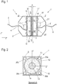
- Figure 1 shows a schematic sectional view of a system according to the application for contactless energy transfer from a primary part 1 to a secondary part 1 '.
- Figure 2 is the primary part 1 in a section along the in Figure 1 shown section line AA reproduced.
- the housings 2 are designed in the form of a half-shell, their front side being closed with a front panel 3. In the rear area, facing away from the front panel 3, a cable bushing 4 for a connection cable 5 is introduced into the housing 2.
- a coil 10 which is wound on a ferrite core 11 or is wound on a coil body which is inserted into the ferrite core 11.
- the coil 10 can be wound with a single conductor. To reduce the skin effect, however, the use of multi-core high-frequency braided wire is preferred.
- the ferrite core 11 is a round pot core on the primary and secondary sides with an outer edge 12 and an inner dome 13 concentric thereto.
- a core is also referred to as a (cylindrically symmetrical) E core.
- the cross-sections of the outer edge 12 and the inner dome 13 are preferably approximately the same size in order to achieve a homogeneous magnetic flux density taking into account the different stray fields in the ferrite core 11.
- the use of ferrite cores with a different geometry is also possible. For example, square or rectangular cores with round or square or rectangular ferrite cores can be used. Coils without coil formers, e.g. with conductors glued together, can also be used.
- the ferrite cores 11 are open towards the respective front plate 3, whereas on the opposite side the outer edge 12 and the inner dome 13 are connected to one another via a pot base.
- the coil 10 is inserted into the here annular trench between the outer edge 12 and the inner dome 13. Any gap that may still be present between the outer and inner edge of the coil 10 and the ferrite core 11 can be filled with a heat-conducting medium.
- the primary part 1 and the secondary part 1 'with their front plates 3, 3' facing one another are brought at a small distance from one another for contactless inductive energy transmission.
- this distance which forms a transmission gap, is shown as transmission distance zo.
- the size of a permissible transmission distance zo is in the range from 0 to a few millimeters or centimeters, depending on the size, in particular the diameter of the coils 10 or ferrite cores 11.
- the direction along the axis of the primary-side coil 10 is hereinafter referred to as the z-direction, the assigned axis referred to as the z-axis.
- the x and y directions or axes run perpendicular to this in the plane of the front panel 3.
- the primary-side coil 10 During operation, the primary-side coil 10, hereinafter also referred to as the primary coil 10, has an alternating current applied to it.
- a resonance circuit is preferably formed from the primary coil 10 and a resonance capacitor, the frequency of which is in the range from a few kilohertz (kHz) to a few hundred kHz, a frequency in the range of a few tens of kHz being particularly preferred.
- the alternating current with which the primary coil 10 is applied is provided by an inverter.
- a pulse width modulation method PWM method
- the inverter is located together with monitoring and control devices on a circuit board 20 within the housing 2 of the primary part 1.
- the secondary coil 10' An energy transfer takes place with a magnetic coupling between the primary coil 10 and the secondary-side coil 10 ', hereinafter referred to as the secondary coil 10'.
- the existing ferrite cores 11 and 11 ' make the coupling particularly efficient.
- a voltage is induced in the secondary coil 10 'which, after rectification, voltage conversion - and, if necessary, voltage stabilization - is available as an output voltage on the connection cable 5' for outputting the transmitted energy.
- the electronic components on the secondary side are also arranged on a circuit board 20 ', with individual electronic components 21' being shown here again by way of example.
- the secondary coil can advantageously have a center tap so that a synchronous rectifier can be used.
- heat-conducting elements for example heat-conducting mats 14 can be arranged between the respective ferrite core 11 and the circuit board 20.
- the electronic components 21 arranged on the circuit board 20 represent a source of loss in the transmission path.
- the heat loss generated by these components 21 is transmitted to the ferrite core 11 via the heat conducting mats 14.
- the ferrite core 11 warms up during operation to a higher operating temperature than would be the case without the thermal coupling to the circuit board 20.
- the losses at a lower temperature in the ferrite core 11 are greater than at a higher temperature over a wide frequency and magnetization range.
- the previously described entry of the power loss of the electronic components as heat into the ferrite core 11 increases its temperature and consequently lowers the power loss in the ferrite core 11 caused by magnetic reversal processes. This improves the overall efficiency of the transmission system. This effect can be used on the primary side as well as on the secondary side.
- the existing ferrite core 11, 11 ' is used as a heat sink for the electronic components 21, 21' due to the thermal coupling, which results in an additional effect in terms of material and thus cost savings.
- a potting compound can also be used, for example, in order to thermally couple the circuit board 20 and the ferrite core 11.
- no interlocking guide or positioning elements are provided that would laterally align the primary part 1 and the secondary part 1 'with one another when they are joined. Due to the lack of such elements, the primary part 1 and the secondary part 1 ′ can also be brought into the operating position or separated from one another by a lateral movement, that is to say a movement in the x and / or y direction. This proves to be particularly advantageous in the automation sector, since an additional axial movement of the primary and secondary parts 1, 1 ′ towards one another is not required to establish or disconnect a connection. Depending on the intended application, such guide or positioning elements can, however, also be provided in alternative configurations.
- the ferrite cores 11, 11 allow a high magnetic flux density, through which an efficient energy transfer is possible even with a small coil volume.
- the transmission is relatively tolerant of a lateral shift the primary part 1 and the secondary part 1 'against each other. This is of great advantage in the automation sector, for example, since high positioning accuracy for establishing a conventional plug-in connection with contacts can be dispensed with.
- the primary part 1 of the energy transmission system for detecting the position of the secondary part 1 ' has at least one magnetic field sensor which determines the stray field of the coils 10, 10'.
- four auxiliary coils 30a, 30b, 30c and 30d are used as magnetic field sensors, which are arranged in four quadrants of the front plate 3 next to the coil 10. Two of the auxiliary coils 30a, 30c or 30b, 30d are symmetrically opposite to the center of the coil 10. The position of the four auxiliary coils 30a, 30b, 30c and 30d is shown in the sectional view of FIG Figure 2 clearly visible. If no explicit reference is made in the following to a single one of the auxiliary coils 30a, 30b, 30c and 30d, the auxiliary coils 30a, 30b, 30c and 30d are collectively identified with the reference symbol 30.
- the auxiliary coils 30 represent receiving coils in which, due to the stray field from the primary and secondary coils 10 or 10 ', a signal is induced which is evaluated by an evaluation circuit on the circuit board 20 of the primary part 1.
- the level of the signals induced in the auxiliary coils 30 is dependent both on the distance zo between the primary and secondary part 1, 1 ′ and on a lateral offset in the x and y directions. This is explained below using the Figures 3 and 4 explained in more detail.
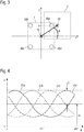
- Figure 3 shows schematically a primary and a secondary part 1, 1 ′ of a system for inductive energy transmission, which are laterally offset to one another.
- the offset is xo in the x direction and yo in the y direction.
- a distance of zo which is not visible in this illustration, can be present between the two parts 1, 1 '.
- the lateral offset xo and yo can also be expressed in polar coordinates and then described via a radial distance ro between the center points of the coils 10 and 10 ', as well as an angle ⁇ between a distance vector and the x-axis.
- Figure 4 shows an example of how signal amplitudes 31 (here voltage amplitudes) change in the four auxiliary coils 30 if the secondary part 1 'is moved in a circle around the z-axis of the primary part 1 with a fixed distance zo and a fixed radial distance ro.
- a resulting respective signal amplitude 31a, 31b, 31c and 31d of the auxiliary coils 30a, 30b, 30c and 30d is shown as a function of the angle ⁇ . It can be seen that, as a first approximation, there is a sinusoidal dependence of the signal amplitude 31 on the angle ⁇ .
- the sinusoids have the same amplitude û and an offset uo that is also the same for all sinusoids.
- the drawn amplitude û depends mainly on the size of the radial distance ro, whereas the offset uo mainly depends on the distance zo between the primary and secondary part 1, 1 '.
- This special dependency which applies when using a ferrite core 11, 11 'in the primary coil 10 or the secondary coil 10', favors and simplifies a separation of the radial distance ro (or the lateral offset xo, yo) and the axial distance zo.
- metallic objects in the vicinity and stray fields from other neighboring components influence the measured signal amplitudes more intensely as the axial distance between the coils increases, which makes it difficult to determine the axial distance zo.
- the dependency is essentially linear, in particular in the case of (compared to the size of the coils 10, 10 ') small values for the radial one Distance ro and the distance zo.
- the proportionality factors for these linear dependencies can be determined beforehand in series of measurements with a constant current of a predetermined level through the primary coil 10 with a known radial distance ro and a known distance z 0 for a given system for energy transmission. Measured values subsequently recorded to determine the distance are then scaled to the conditions when the proportionality factors are recorded with regard to the current level of the current through the primary coil 10.
- the height of the four signal amplitudes 31a, 31b, 31c and 31d is first measured for an unknown distance zo, an unknown radial distance ro and an unknown angle ⁇ .
- the sinusoidal component of the signal amplitudes 31 cancels one another, whereby the size of the offset uo can be determined.
- the offsets uo can also be determined for both pairs of opposing auxiliary coils 31a, 31c and 31b, 31d and thus ultimately by adding up all four signal amplitudes 31a-31d. With the previously determined proportionality factor and scaling to the level of the current current through the primary coil 10, the size of the distance zo follows from the size of the offset uo.
- the size of the angle ⁇ can be determined by forming the difference between two signal amplitudes 31a and 31c or 31b and 31d of two opposing auxiliary coils 30a and 30c or 30b and 30d via angle functions.
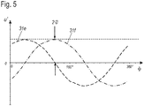
- the differences u 'of two signals in each case are shown as difference amplitudes 31e and 31f, again as a function of the angle ⁇ .
- the difference signal 31e is made up of the signal amplitudes 31a and 31c and the difference signal 31f from the signal amplitudes 31b and 31d.
- the two difference signals 31e and 31f also run sinusoidally with a phase shift of 90 ° to one another.
- the difference signals 31e, 31f show no offset and their signal amplitudes only depend on the offset, i.e. the radial distance ro.
- the magnitude of the radial distance ro follows from one of the amplitudes of the difference signals 31e, 31f.
- the amplitude of the difference signals 31e, 31f is twice as large as that of the amplitude û of the signal amplitudes 31a-d.
- the angle ⁇ i.e. the direction in which the offset is present, can finally be determined via trigonometric functions.
- the phase position of the difference signals 31e or 31f can advantageously be determined at their zero crossing points.
- both the radial distance ro and the direction (angle ⁇ ) of a lateral offset between the primary and secondary part 1,1 can be obtained from the height of the signal induced in them by the stray field of the coils 10, 10 'using the four auxiliary coils 30 'are determined, and also the distance zo between the primary and secondary part 1, 1'.
- the information about the lateral offset can be converted from the polar coordinates (radial distance ro, angle ⁇ ) into Cartesian coordinates (xo, yo) and specified.
- an automation controller can identify a problem with the positioning of the primary and secondary parts 1, 1 ′ with respect to one another, which indicates a fault in a robot that uses the system for energy transfer. It can further be provided that the energy transfer from the primary part 1 to the secondary part 1 'is interrupted or not even established in an initialization step if one is determined lateral offset (xo, yo or ro) and / or a determined distance zo are above defined limit values.
- the limit values can take into account in the form of tables or a functional context to what extent a simultaneous combination of lateral offset and distance is permitted.
- the method shown has the advantage that an incorrectly positioned secondary side is recognized on the primary side. No feedback from the secondary part 1 ′ to the primary part 1 is necessary in order to guarantee safe operation of the primary part 1.
- a safety mechanism based on feedback from a secondary part to a primary part can also be used with regard to positioning.
- the connector can also be provided to determine information about the lateral offset and / or the distance on the basis of a detuning of the resonance circuit via the resonance frequency, possibly in connection with the current flowing in the primary coil.
- This additional measurement can serve as a control measurement for the previously described distance determination via the auxiliary coils 30 in order to additionally increase the transmission reliability.
Landscapes
- Engineering & Computer Science (AREA)
- Power Engineering (AREA)
- Computer Networks & Wireless Communication (AREA)
- Transportation (AREA)
- Mechanical Engineering (AREA)
- Life Sciences & Earth Sciences (AREA)
- Sustainable Development (AREA)
- Sustainable Energy (AREA)
- Measurement Of Length, Angles, Or The Like Using Electric Or Magnetic Means (AREA)
- Charge And Discharge Circuits For Batteries Or The Like (AREA)
- Measuring Magnetic Variables (AREA)
- Near-Field Transmission Systems (AREA)
Claims (13)
- Système de transmission d'énergie inductive sans contact d'une partie primaire (1) à une partie secondaire (1'), dont chacune présente au moins une bobine (10, 10') pouvant être couplées entre elles par induction, la partie primaire (1) et/ou la partie secondaire (1') présentant au moins un capteur de champ magnétique et étant conçue pour déterminer un décalage latéral de la partie secondaire (1') par rapport à la partie primaire (1) sur la base d'un champ magnétique généré par les bobines (10, 10') et mesuré à l'aide dudit au moins un capteur de champ magnétique, caractérisé en ce que le système est en outre conçu de telle sorte que le champ magnétique mesuré par ledit au moins un capteur de champ magnétique est un champ parasite de ladite au moins une bobine (10) de la partie primaire (1) et de ladite au moins une bobine de la partie secondaire (1') qui est généré pendant la transmission d'énergie et pour déterminer une distance (zo) le long d'un axe de la bobine côté primaire (10) entre la partie secondaire (1') et la partie primaire (1) à l'aide du champ parasite mesuré par ledit au moins un capteur de champ magnétique.
- Système selon la revendication 1, dans lequel ledit au moins un capteur de champ magnétique est au moins une bobine auxiliaire (30) dans laquelle les bobines (10, 10') induisent un signal.
- Système selon la revendication 1 ou 2, dans lequel ledit au moins un capteur de champ magnétique est disposé dans la partie primaire (1).
- Système selon l'une des revendications 1 à 3, dans lequel ledit au moins un capteur de champ magnétique est disposé dans la partie primaire ou secondaire (1, 1') en étant décalé latéralement par rapport à la bobine respective (10, 10').
- Système selon la revendication 4, dans lequel au moins deux capteurs de champ magnétique sont disposés dans la partie primaire et/ou secondaire (1, 1 '), qui sont disposés symétriquement par paires autour d'un axe longitudinal de la bobine respective (10, 10').
- Système selon la revendication 4, dans lequel quatre capteurs de champ magnétique sont disposés dans la partie primaire et/ou secondaire (1, 1') autour de la bobine respective (10, 10').
- Procédé de fonctionnement d'un système de transmission d'énergie inductive sans contact d'une bobine (10) d'une partie primaire (1) à une bobine (10') d'une partie secondaire (1'), dans lequel un décalage latéral de la partie secondaire (1') par rapport à la partie primaire (1) est déterminé sur la base d'un champ magnétique généré par les bobines (10, 10') et mesuré avec au moins un capteur de champ magnétique, caractérisé en ce que ladite au moins une bobine (10) de la partie primaire (1) et ladite au moins une bobine de la partie secondaire (1') génèrent, pendant la transmission d'énergie, un champ parasite qui est mesuré par ledit au moins un capteur de champ magnétique et qu'une distance (zo) le long d'un axe de la bobine côté primaire (10) entre la partie secondaire (1') et la partie primaire (1) est en outre déterminée à l'aide du champ parasite mesuré par ledit au moins un capteur de champ magnétique.
- Procédé de fonctionnement selon la revendication 7, dans lequel le décalage latéral et la distance (zo) sont déterminés à partir des valeurs mesurées par quatre capteurs de champ magnétique qui sont disposés dans la partie primaire (1) autour de sa bobine (10).
- Procédé de fonctionnement selon la revendication 7 ou 8, dans lequel au moins une bobine auxiliaire (30) est utilisée comme au moins un capteur de champ magnétique, un signal induit dans ladite au moins une bobine auxiliaire (30) étant mesuré.
- Procédé de fonctionnement selon la revendication 9, dans lequel une amplitude de signal (31), en particulier une amplitude de tension, de ladite au moins une bobine auxiliaire (30) est évaluée comme signal.
- Procédé de fonctionnement selon la revendication 10, dans lequel les amplitudes de signal (31) de chaque fois deux bobines auxiliaires (30) opposées par paires sont mutuellement compensées pour déterminer le décalage latéral de la partie secondaire (1') par rapport à la partie primaire (1) et pour déterminer la distance (zo) entre la partie secondaire (1') et la partie primaire (1).
- Procédé de fonctionnement selon la revendication 11, dans lequel le décalage latéral comprend une distance radiale (ro) entre les axes des bobines (10, 10') ainsi qu'un angle (φ) entre un vecteur distance, qui s'étend de l'axe de la bobine (10) de la partie primaire (1) à l'axe de la bobine (10') de la partie secondaire (1'), et une direction spatiale définie.
- Procédé de fonctionnement selon la revendication 11 ou 12, dans lequel une transmission d'énergie de la partie primaire (1) à la partie secondaire (1') est empêchée si le décalage latéral de la partie secondaire (1') par rapport à la partie primaire (1) et/ou la distance (zo) entre la partie secondaire (1') et la partie primaire (1) dépasse une valeur limite prédéfinie.
Applications Claiming Priority (3)
| Application Number | Priority Date | Filing Date | Title |
|---|---|---|---|
| DE102015105359 | 2015-04-09 | ||
| DE102015113723.2A DE102015113723A1 (de) | 2015-04-09 | 2015-08-19 | Vorrichtung zur kontaktlosen induktiven Energieübertragung und Betriebsverfahren für eine derartige Vorrichtung |
| PCT/EP2016/057826 WO2016162520A1 (fr) | 2015-04-09 | 2016-04-08 | Dispositif de transfert d'énergie par induction sans contact et procédé de fonctionnement d'un tel dispositif |
Publications (2)
| Publication Number | Publication Date |
|---|---|
| EP3281275A1 EP3281275A1 (fr) | 2018-02-14 |
| EP3281275B1 true EP3281275B1 (fr) | 2021-10-13 |
Family
ID=56986417
Family Applications (1)
| Application Number | Title | Priority Date | Filing Date |
|---|---|---|---|
| EP16715848.4A Active EP3281275B1 (fr) | 2015-04-09 | 2016-04-08 | Dispositif de transfert d'énergie par induction sans contact et procédé de fonctionnement d'un tel dispositif |
Country Status (7)
| Country | Link |
|---|---|
| US (1) | US10505399B2 (fr) |
| EP (1) | EP3281275B1 (fr) |
| JP (1) | JP2018512837A (fr) |
| CN (1) | CN107431386B (fr) |
| DE (1) | DE102015113723A1 (fr) |
| ES (1) | ES2898674T3 (fr) |
| WO (1) | WO2016162520A1 (fr) |
Families Citing this family (10)
| Publication number | Priority date | Publication date | Assignee | Title |
|---|---|---|---|---|
| CN108297704A (zh) * | 2017-01-11 | 2018-07-20 | 宁波轩悦行电动汽车服务有限公司 | 电动汽车还车处理系统 |
| DE102017108302A1 (de) | 2017-04-19 | 2018-10-25 | Weidmüller Interface GmbH & Co. KG | Vorrichtung zur kontaktlosen induktiven Energieübertragung und Verfahren zum Betreiben der Vorrichtung |
| DE202017107131U1 (de) * | 2017-11-24 | 2019-01-10 | Bombardier Primove Gmbh | Beweglicher Teil einer Einrichtung zur induktiven Energieübertragung sowie Einrichtung zur induktiven Energieübertragung |
| US10790711B2 (en) * | 2017-12-21 | 2020-09-29 | Korea Advanced Institute Of Science And Technology | Magnetic field generating apparatus having cannon shape and magnetic field generation method thereof |
| DE102018120779B3 (de) | 2018-08-24 | 2019-12-12 | Phoenix Contact Gmbh & Co. Kg | Kontaktloses PoE-Verbindungssystem |
| CN109883309B (zh) * | 2019-01-28 | 2021-04-27 | 中国船舶重工集团公司第七一五研究所 | 一种基于磁性感应原理的缆绳到位传感装置 |
| CN109895643B (zh) * | 2019-02-26 | 2020-07-07 | 浙江大学 | 一种基于差分电感的在线式电动汽车无线充电定位系统 |
| US11505077B2 (en) * | 2020-05-27 | 2022-11-22 | Toyota Motor Engineering & Manufacturing North America, Inc. | Systems and methods for wireless vehicle power transfer and misalignment estimation |
| CN114050665B (zh) * | 2022-01-17 | 2022-04-12 | 广东电网有限责任公司佛山供电局 | 一种用于三相电缆在线监测的工作电源 |
| DE102023126699A1 (de) * | 2023-09-29 | 2025-04-03 | Mahle International Gmbh | Induktive Ladeeinrichtung für ein Fahrzeug |
Citations (2)
| Publication number | Priority date | Publication date | Assignee | Title |
|---|---|---|---|---|
| JP2013031315A (ja) * | 2011-07-29 | 2013-02-07 | Toko Inc | ワイヤレス電力伝送装置および相対位置検出方法 |
| JP2013078198A (ja) * | 2011-09-30 | 2013-04-25 | Toko Inc | ワイヤレス電力伝送装置および相対位置検出方法 |
Family Cites Families (16)
| Publication number | Priority date | Publication date | Assignee | Title |
|---|---|---|---|---|
| CN101160703B (zh) | 2005-04-12 | 2011-06-15 | 先进装配系统有限责任两合公司 | 用于无接触电流供电装置的初级部件和电流供电装置 |
| JP2009089465A (ja) * | 2007-09-27 | 2009-04-23 | Panasonic Corp | 充電器および充電システム |
| CN101809842A (zh) * | 2007-09-27 | 2010-08-18 | 松下电器产业株式会社 | 电子装置、充电器和充电装置 |
| JP2010130729A (ja) * | 2008-11-25 | 2010-06-10 | Canon Inc | 充電装置、送電装置及び非接触充電システム |
| US20130207893A1 (en) * | 2009-04-29 | 2013-08-15 | Kye Systems Corp. | Positioning input system with wireless charging function, and device |
| US8473066B2 (en) * | 2009-07-06 | 2013-06-25 | Boston Scientific Neuromodulation Company | External charger for a medical implantable device using field sensing coils to improve coupling |
| JP2012034546A (ja) * | 2010-08-03 | 2012-02-16 | Panasonic Corp | 無線電力伝送システム |
| US10090885B2 (en) * | 2011-04-13 | 2018-10-02 | Qualcomm Incorporated | Antenna alignment and vehicle guidance for wireless charging of electric vehicles |
| DE102011056265A1 (de) | 2011-12-12 | 2013-06-13 | Weidmüller Interface GmbH & Co. KG | Steckvorrichtung zur kontaktlosen induktiven Energieübertragung und Betriebsverfahren für eine solche Steckvorrichtung |
| FR2989529B1 (fr) * | 2012-04-12 | 2016-04-15 | Continental Automotive France | Procede et banc de charge par couplage magnetique |
| JP6059522B2 (ja) * | 2012-04-17 | 2017-01-11 | 日東電工株式会社 | 無線電力供給システム、給電装置、受電装置、及び、磁界空間の形成方法 |
| KR101949127B1 (ko) | 2013-08-01 | 2019-02-18 | 삼성전자주식회사 | 하이브리드 동기화 기법을 적용한 무선 에너지 수신 방법 및 장치 |
| JP6125948B2 (ja) * | 2013-08-12 | 2017-05-10 | 本田技研工業株式会社 | 非接触充電装置 |
| US9537353B1 (en) * | 2014-06-03 | 2017-01-03 | Apple Inc. | Methods for detecting mated coils |
| US9829599B2 (en) * | 2015-03-23 | 2017-11-28 | Schneider Electric USA, Inc. | Sensor and method for foreign object detection in induction electric charger |
| US10034704B2 (en) * | 2015-06-30 | 2018-07-31 | Ethicon Llc | Surgical instrument with user adaptable algorithms |
-
2015
- 2015-08-19 DE DE102015113723.2A patent/DE102015113723A1/de not_active Withdrawn
-
2016
- 2016-04-08 WO PCT/EP2016/057826 patent/WO2016162520A1/fr not_active Ceased
- 2016-04-08 ES ES16715848T patent/ES2898674T3/es active Active
- 2016-04-08 JP JP2017552961A patent/JP2018512837A/ja active Pending
- 2016-04-08 EP EP16715848.4A patent/EP3281275B1/fr active Active
- 2016-04-08 US US15/557,265 patent/US10505399B2/en active Active
- 2016-04-08 CN CN201680018030.2A patent/CN107431386B/zh active Active
Patent Citations (2)
| Publication number | Priority date | Publication date | Assignee | Title |
|---|---|---|---|---|
| JP2013031315A (ja) * | 2011-07-29 | 2013-02-07 | Toko Inc | ワイヤレス電力伝送装置および相対位置検出方法 |
| JP2013078198A (ja) * | 2011-09-30 | 2013-04-25 | Toko Inc | ワイヤレス電力伝送装置および相対位置検出方法 |
Also Published As
| Publication number | Publication date |
|---|---|
| US20180062444A1 (en) | 2018-03-01 |
| CN107431386B (zh) | 2021-05-07 |
| CN107431386A (zh) | 2017-12-01 |
| ES2898674T3 (es) | 2022-03-08 |
| US10505399B2 (en) | 2019-12-10 |
| DE102015113723A1 (de) | 2016-10-13 |
| JP2018512837A (ja) | 2018-05-17 |
| WO2016162520A1 (fr) | 2016-10-13 |
| EP3281275A1 (fr) | 2018-02-14 |
Similar Documents
| Publication | Publication Date | Title |
|---|---|---|
| EP3281275B1 (fr) | Dispositif de transfert d'énergie par induction sans contact et procédé de fonctionnement d'un tel dispositif | |
| EP3523816B1 (fr) | Dispositif de transfert d'énergie par induction sans contact et procédé de fonctionnement d'un tel dispositif | |
| EP2895889B1 (fr) | Système de détection de corps étrangers en métal pour des systèmes de transmission d'énergie inductive | |
| EP2791950B1 (fr) | Dispositif enfichable pour le transfert d'énergie par induction sans contact et procédé pour faire fonctionner un tel dispositif enfichable | |
| EP3008474B1 (fr) | Système de détection de courant équipé de bobines de mesure | |
| DE112012003875T5 (de) | Kontaktlose Stromversorungsvorrichtung | |
| EP2550174A2 (fr) | Système de transfert d'énergie sans contact sur un véhicule | |
| DE102014202747A1 (de) | Vorrichtung zum Erfassung einer Lageabweichung der passiven Spule gegenüber der Primärspule eines induktiven Ladesystems für ein Fahrzeug sowie zugehöriges Verfahren | |
| DE102015121960A1 (de) | Induktive drahtlose Energieübertragungssysteme | |
| DE102013100246A1 (de) | Stromsensor- und Entstörfilteranordnung, insbesondere für transformatorlose Photovoltaik-Wechselrichter | |
| WO2017092950A1 (fr) | Procédé de fonctionnement d'un dispositif de surveillance d'un dispositif de transfert d'énergie par induction | |
| WO2013189530A1 (fr) | Module à bobines de détection, module à bobines de transfert d'énergie et système de détection pour la reconnaissance de corps étrangers électriquement conducteurs | |
| EP1011187A1 (fr) | Dispositif pour la transmission sans contact et par induction de l'énergie | |
| WO2014198601A1 (fr) | Système de détection de courant | |
| EP2852818B1 (fr) | Procédé et installation de type inductif de détermination de la position d'une unité mobile | |
| WO2017001464A1 (fr) | Dispositif de soudage par ultrasons | |
| EP2714319A2 (fr) | Dispositif de soudure par ultrasons comprenant un coupleur rotatif | |
| EP3776780A1 (fr) | Procédé et dispositif de détection d'un court-circuit entre spires dans des enroulements disposés en parallèle | |
| EP3350607B1 (fr) | Procédé de mesure destiné à la détermination de pertes de fer | |
| DE102015121956A1 (de) | Induktive drahtlose Energieübertragungssysteme | |
| EP2700140B1 (fr) | Système de transmission inductive d'énergie à un récepteur électrique | |
| DE102007024293A1 (de) | Anlage | |
| EP3613126B1 (fr) | Dispositif pour la transmission inductive d'énergie sans contact et procédé pour le fonctionnement du dispositif | |
| EP3559684A1 (fr) | Dispositif et procédé permettant de protéger une personne contre un signal électrique | |
| EP3323186B1 (fr) | Agencement permettant la transmission inductive d'une énergie électrique depuis un conducteur primaire stationnaire vers un dispositif mobile par rapport audit conducteur primaire et procédé permettant de faire fonctionner cet agencement |
Legal Events
| Date | Code | Title | Description |
|---|---|---|---|
| STAA | Information on the status of an ep patent application or granted ep patent |
Free format text: STATUS: THE INTERNATIONAL PUBLICATION HAS BEEN MADE |
|
| PUAI | Public reference made under article 153(3) epc to a published international application that has entered the european phase |
Free format text: ORIGINAL CODE: 0009012 |
|
| STAA | Information on the status of an ep patent application or granted ep patent |
Free format text: STATUS: REQUEST FOR EXAMINATION WAS MADE |
|
| 17P | Request for examination filed |
Effective date: 20171019 |
|
| AK | Designated contracting states |
Kind code of ref document: A1 Designated state(s): AL AT BE BG CH CY CZ DE DK EE ES FI FR GB GR HR HU IE IS IT LI LT LU LV MC MK MT NL NO PL PT RO RS SE SI SK SM TR |
|
| AX | Request for extension of the european patent |
Extension state: BA ME |
|
| DAV | Request for validation of the european patent (deleted) | ||
| DAX | Request for extension of the european patent (deleted) | ||
| STAA | Information on the status of an ep patent application or granted ep patent |
Free format text: STATUS: EXAMINATION IS IN PROGRESS |
|
| 17Q | First examination report despatched |
Effective date: 20190116 |
|
| RAP1 | Party data changed (applicant data changed or rights of an application transferred) |
Owner name: WEIDMUELLER INTERFACE GMBH & CO. KG |
|
| REG | Reference to a national code |
Ref country code: DE Ref legal event code: R079 Ref document number: 502016013984 Country of ref document: DE Free format text: PREVIOUS MAIN CLASS: H02J0050100000 Ipc: H02J0050000000 |
|
| RIC1 | Information provided on ipc code assigned before grant |
Ipc: B60L 53/126 20190101ALI20210507BHEP Ipc: B60L 53/34 20190101ALI20210507BHEP Ipc: H01F 38/14 20060101ALI20210507BHEP Ipc: H02J 50/90 20160101ALI20210507BHEP Ipc: H02J 50/10 20160101ALI20210507BHEP Ipc: H02J 50/00 20160101AFI20210507BHEP |
|
| GRAP | Despatch of communication of intention to grant a patent |
Free format text: ORIGINAL CODE: EPIDOSNIGR1 |
|
| STAA | Information on the status of an ep patent application or granted ep patent |
Free format text: STATUS: GRANT OF PATENT IS INTENDED |
|
| INTG | Intention to grant announced |
Effective date: 20210630 |
|
| GRAS | Grant fee paid |
Free format text: ORIGINAL CODE: EPIDOSNIGR3 |
|
| GRAA | (expected) grant |
Free format text: ORIGINAL CODE: 0009210 |
|
| STAA | Information on the status of an ep patent application or granted ep patent |
Free format text: STATUS: THE PATENT HAS BEEN GRANTED |
|
| AK | Designated contracting states |
Kind code of ref document: B1 Designated state(s): AL AT BE BG CH CY CZ DE DK EE ES FI FR GB GR HR HU IE IS IT LI LT LU LV MC MK MT NL NO PL PT RO RS SE SI SK SM TR |
|
| REG | Reference to a national code |
Ref country code: GB Ref legal event code: FG4D Free format text: NOT ENGLISH |
|
| REG | Reference to a national code |
Ref country code: CH Ref legal event code: EP |
|
| REG | Reference to a national code |
Ref country code: DE Ref legal event code: R096 Ref document number: 502016013984 Country of ref document: DE |
|
| REG | Reference to a national code |
Ref country code: IE Ref legal event code: FG4D Free format text: LANGUAGE OF EP DOCUMENT: GERMAN |
|
| REG | Reference to a national code |
Ref country code: AT Ref legal event code: REF Ref document number: 1438877 Country of ref document: AT Kind code of ref document: T Effective date: 20211115 |
|
| REG | Reference to a national code |
Ref country code: LT Ref legal event code: MG9D |
|
| REG | Reference to a national code |
Ref country code: NL Ref legal event code: MP Effective date: 20211013 |
|
| REG | Reference to a national code |
Ref country code: ES Ref legal event code: FG2A Ref document number: 2898674 Country of ref document: ES Kind code of ref document: T3 Effective date: 20220308 |
|
| PG25 | Lapsed in a contracting state [announced via postgrant information from national office to epo] |
Ref country code: RS Free format text: LAPSE BECAUSE OF FAILURE TO SUBMIT A TRANSLATION OF THE DESCRIPTION OR TO PAY THE FEE WITHIN THE PRESCRIBED TIME-LIMIT Effective date: 20211013 Ref country code: LT Free format text: LAPSE BECAUSE OF FAILURE TO SUBMIT A TRANSLATION OF THE DESCRIPTION OR TO PAY THE FEE WITHIN THE PRESCRIBED TIME-LIMIT Effective date: 20211013 Ref country code: FI Free format text: LAPSE BECAUSE OF FAILURE TO SUBMIT A TRANSLATION OF THE DESCRIPTION OR TO PAY THE FEE WITHIN THE PRESCRIBED TIME-LIMIT Effective date: 20211013 Ref country code: BG Free format text: LAPSE BECAUSE OF FAILURE TO SUBMIT A TRANSLATION OF THE DESCRIPTION OR TO PAY THE FEE WITHIN THE PRESCRIBED TIME-LIMIT Effective date: 20220113 |
|
| PG25 | Lapsed in a contracting state [announced via postgrant information from national office to epo] |
Ref country code: IS Free format text: LAPSE BECAUSE OF FAILURE TO SUBMIT A TRANSLATION OF THE DESCRIPTION OR TO PAY THE FEE WITHIN THE PRESCRIBED TIME-LIMIT Effective date: 20220213 Ref country code: SE Free format text: LAPSE BECAUSE OF FAILURE TO SUBMIT A TRANSLATION OF THE DESCRIPTION OR TO PAY THE FEE WITHIN THE PRESCRIBED TIME-LIMIT Effective date: 20211013 Ref country code: PT Free format text: LAPSE BECAUSE OF FAILURE TO SUBMIT A TRANSLATION OF THE DESCRIPTION OR TO PAY THE FEE WITHIN THE PRESCRIBED TIME-LIMIT Effective date: 20220214 Ref country code: PL Free format text: LAPSE BECAUSE OF FAILURE TO SUBMIT A TRANSLATION OF THE DESCRIPTION OR TO PAY THE FEE WITHIN THE PRESCRIBED TIME-LIMIT Effective date: 20211013 Ref country code: NO Free format text: LAPSE BECAUSE OF FAILURE TO SUBMIT A TRANSLATION OF THE DESCRIPTION OR TO PAY THE FEE WITHIN THE PRESCRIBED TIME-LIMIT Effective date: 20220113 Ref country code: NL Free format text: LAPSE BECAUSE OF FAILURE TO SUBMIT A TRANSLATION OF THE DESCRIPTION OR TO PAY THE FEE WITHIN THE PRESCRIBED TIME-LIMIT Effective date: 20211013 Ref country code: LV Free format text: LAPSE BECAUSE OF FAILURE TO SUBMIT A TRANSLATION OF THE DESCRIPTION OR TO PAY THE FEE WITHIN THE PRESCRIBED TIME-LIMIT Effective date: 20211013 Ref country code: HR Free format text: LAPSE BECAUSE OF FAILURE TO SUBMIT A TRANSLATION OF THE DESCRIPTION OR TO PAY THE FEE WITHIN THE PRESCRIBED TIME-LIMIT Effective date: 20211013 Ref country code: GR Free format text: LAPSE BECAUSE OF FAILURE TO SUBMIT A TRANSLATION OF THE DESCRIPTION OR TO PAY THE FEE WITHIN THE PRESCRIBED TIME-LIMIT Effective date: 20220114 |
|
| REG | Reference to a national code |
Ref country code: DE Ref legal event code: R097 Ref document number: 502016013984 Country of ref document: DE |
|
| PG25 | Lapsed in a contracting state [announced via postgrant information from national office to epo] |
Ref country code: SM Free format text: LAPSE BECAUSE OF FAILURE TO SUBMIT A TRANSLATION OF THE DESCRIPTION OR TO PAY THE FEE WITHIN THE PRESCRIBED TIME-LIMIT Effective date: 20211013 Ref country code: SK Free format text: LAPSE BECAUSE OF FAILURE TO SUBMIT A TRANSLATION OF THE DESCRIPTION OR TO PAY THE FEE WITHIN THE PRESCRIBED TIME-LIMIT Effective date: 20211013 Ref country code: EE Free format text: LAPSE BECAUSE OF FAILURE TO SUBMIT A TRANSLATION OF THE DESCRIPTION OR TO PAY THE FEE WITHIN THE PRESCRIBED TIME-LIMIT Effective date: 20211013 Ref country code: DK Free format text: LAPSE BECAUSE OF FAILURE TO SUBMIT A TRANSLATION OF THE DESCRIPTION OR TO PAY THE FEE WITHIN THE PRESCRIBED TIME-LIMIT Effective date: 20211013 |
|
| PLBE | No opposition filed within time limit |
Free format text: ORIGINAL CODE: 0009261 |
|
| STAA | Information on the status of an ep patent application or granted ep patent |
Free format text: STATUS: NO OPPOSITION FILED WITHIN TIME LIMIT |
|
| 26N | No opposition filed |
Effective date: 20220714 |
|
| PG25 | Lapsed in a contracting state [announced via postgrant information from national office to epo] |
Ref country code: AL Free format text: LAPSE BECAUSE OF FAILURE TO SUBMIT A TRANSLATION OF THE DESCRIPTION OR TO PAY THE FEE WITHIN THE PRESCRIBED TIME-LIMIT Effective date: 20211013 |
|
| PG25 | Lapsed in a contracting state [announced via postgrant information from national office to epo] |
Ref country code: SI Free format text: LAPSE BECAUSE OF FAILURE TO SUBMIT A TRANSLATION OF THE DESCRIPTION OR TO PAY THE FEE WITHIN THE PRESCRIBED TIME-LIMIT Effective date: 20211013 |
|
| REG | Reference to a national code |
Ref country code: CH Ref legal event code: PL |
|
| GBPC | Gb: european patent ceased through non-payment of renewal fee |
Effective date: 20220408 |
|
| REG | Reference to a national code |
Ref country code: BE Ref legal event code: MM Effective date: 20220430 |
|
| PG25 | Lapsed in a contracting state [announced via postgrant information from national office to epo] |
Ref country code: MC Free format text: LAPSE BECAUSE OF FAILURE TO SUBMIT A TRANSLATION OF THE DESCRIPTION OR TO PAY THE FEE WITHIN THE PRESCRIBED TIME-LIMIT Effective date: 20211013 Ref country code: LU Free format text: LAPSE BECAUSE OF NON-PAYMENT OF DUE FEES Effective date: 20220408 Ref country code: LI Free format text: LAPSE BECAUSE OF NON-PAYMENT OF DUE FEES Effective date: 20220430 Ref country code: GB Free format text: LAPSE BECAUSE OF NON-PAYMENT OF DUE FEES Effective date: 20220408 Ref country code: CH Free format text: LAPSE BECAUSE OF NON-PAYMENT OF DUE FEES Effective date: 20220430 |
|
| PG25 | Lapsed in a contracting state [announced via postgrant information from national office to epo] |
Ref country code: BE Free format text: LAPSE BECAUSE OF NON-PAYMENT OF DUE FEES Effective date: 20220430 |
|
| PG25 | Lapsed in a contracting state [announced via postgrant information from national office to epo] |
Ref country code: IE Free format text: LAPSE BECAUSE OF NON-PAYMENT OF DUE FEES Effective date: 20220408 |
|
| REG | Reference to a national code |
Ref country code: AT Ref legal event code: MM01 Ref document number: 1438877 Country of ref document: AT Kind code of ref document: T Effective date: 20220408 |
|
| P01 | Opt-out of the competence of the unified patent court (upc) registered |
Effective date: 20230518 |
|
| PG25 | Lapsed in a contracting state [announced via postgrant information from national office to epo] |
Ref country code: AT Free format text: LAPSE BECAUSE OF NON-PAYMENT OF DUE FEES Effective date: 20220408 |
|
| PG25 | Lapsed in a contracting state [announced via postgrant information from national office to epo] |
Ref country code: HU Free format text: LAPSE BECAUSE OF FAILURE TO SUBMIT A TRANSLATION OF THE DESCRIPTION OR TO PAY THE FEE WITHIN THE PRESCRIBED TIME-LIMIT; INVALID AB INITIO Effective date: 20160408 |
|
| PG25 | Lapsed in a contracting state [announced via postgrant information from national office to epo] |
Ref country code: MK Free format text: LAPSE BECAUSE OF FAILURE TO SUBMIT A TRANSLATION OF THE DESCRIPTION OR TO PAY THE FEE WITHIN THE PRESCRIBED TIME-LIMIT Effective date: 20211013 Ref country code: CY Free format text: LAPSE BECAUSE OF FAILURE TO SUBMIT A TRANSLATION OF THE DESCRIPTION OR TO PAY THE FEE WITHIN THE PRESCRIBED TIME-LIMIT Effective date: 20211013 |
|
| PG25 | Lapsed in a contracting state [announced via postgrant information from national office to epo] |
Ref country code: TR Free format text: LAPSE BECAUSE OF FAILURE TO SUBMIT A TRANSLATION OF THE DESCRIPTION OR TO PAY THE FEE WITHIN THE PRESCRIBED TIME-LIMIT Effective date: 20211013 |
|
| PG25 | Lapsed in a contracting state [announced via postgrant information from national office to epo] |
Ref country code: MT Free format text: LAPSE BECAUSE OF FAILURE TO SUBMIT A TRANSLATION OF THE DESCRIPTION OR TO PAY THE FEE WITHIN THE PRESCRIBED TIME-LIMIT Effective date: 20211013 |
|
| PGFP | Annual fee paid to national office [announced via postgrant information from national office to epo] |
Ref country code: RO Payment date: 20250331 Year of fee payment: 10 |
|
| PGFP | Annual fee paid to national office [announced via postgrant information from national office to epo] |
Ref country code: DE Payment date: 20250422 Year of fee payment: 10 |
|
| PGFP | Annual fee paid to national office [announced via postgrant information from national office to epo] |
Ref country code: ES Payment date: 20250529 Year of fee payment: 10 |
|
| PGFP | Annual fee paid to national office [announced via postgrant information from national office to epo] |
Ref country code: IT Payment date: 20250424 Year of fee payment: 10 |
|
| PGFP | Annual fee paid to national office [announced via postgrant information from national office to epo] |
Ref country code: FR Payment date: 20250425 Year of fee payment: 10 |
|
| PGFP | Annual fee paid to national office [announced via postgrant information from national office to epo] |
Ref country code: CZ Payment date: 20250401 Year of fee payment: 10 |